

HP 5900AF-48XG-4QSFP+, JG296A, 5900AF-48XG-4QSFP+ TAA, 5900AF-48XGT-4QSFP+, 5900AF-48G-4XG-2QSFP+ Installation Manual
...
HP 5920&5900 Switch Series
Installation Guide
Part number: 5998-2852
Document version: 6W101-20130123
5998-2852

Legal and notice information
© Copyright 2012-2013 Hewlett-Packard Development Company, L.P.
No part of this documentation may be reproduced or transmitted in any form or by any means without
prior written consent of Hewlett-Packard Development Company, L.P.
The information contained herein is subject to change without notice.
HEWLETT-PACKARD COMPANY MAKES NO WARRANTY OF ANY KIND WITH REGARD TO THIS
MATERIAL, INCLUDING, BUT NOT LIMITED TO, THE IMPLIED WARRANTIES OF MERCHANTABILITY
AND FITNESS FOR A PARTICULAR PURPOSE. Hewlett-Packard shall not be liable for errors contained
herein or for incidental or consequential damages in connection with the furnishing, performance, or
use of this material.
The only warranties for HP products and services are set forth in the express warranty statements
accompanying such products and services. Nothing herein should be construed as constituting an
additional warranty. HP shall not be liable for technical or editorial errors or omissions contained
herein.

i
Contents
Product overview ·························································································································································· 1
HP 5920AF-24XG/HP 5920AF-24XG TAA panel views ···························································································· 2
HP 5900AF-48XG-4QSFP+/HP 5900AF-48XG-4QSFP+ TAA panel views ······························································ 3
HP 5900AF-48XGT-4QSFP+ panel views ······················································································································ 4
HP 5900AF-48G-4XG-2QSFP+ panel views ················································································································· 5
Preparing for installation ············································································································································· 7
Safety recommendations ·················································································································································· 7
Examining the installation site ········································································································································· 7
Temperature/humidity ············································································································································· 7
Cleanness ·································································································································································· 8
EMI ············································································································································································· 8
Laser safety ································································································································································ 9
Installation tools ································································································································································· 9
Installing the switch ···················································································································································· 10
Installing the switch in a 19-inch rack ·························································································································· 10
Installation prerequisites ······································································································································· 10
Mounting bracket and rack mounting rail kits ··································································································· 11
Rack-mounting procedures at a glance ··············································································································· 11
Attaching the mounting brackets, chassis rails, and grounding cable to the chassis ···································· 11
Attaching the slide rails to the rack ····················································································································· 15
Mounting the switch in the rack ··························································································································· 15
Grounding the switch ···················································································································································· 17
Grounding the switch with a grounding strip ····································································································· 17
Grounding the switch by using the AC power cord ·························································································· 18
Installing/removing a fan tray ······································································································································ 19
Installing a fan tray ··············································································································································· 19
Removing a fan tray ·············································································································································· 20
Installing/removing a power supply ···························································································································· 21
Installing a power supply ····································································································································· 21
Removing a power supply ···································································································································· 23
Connecting the power cord ·········································································································································· 24
Connecting the 650W AC power supply ·········································································································· 24
Connecting the 650W DC power supply ··········································································································· 24
Verifying the installation ················································································································································ 25
Accessing the switch for the first time ······················································································································· 26
Setting up the configuration environment ···················································································································· 26
Connecting the console cable ······································································································································ 26
Console cable ························································································································································ 26
Connection procedure ·········································································································································· 26
Setting terminal parameters ·········································································································································· 27
Powering on the switch·················································································································································· 30
Setting up an IRF fabric ············································································································································· 31
IRF fabric setup flowchart ·············································································································································· 31
Planning IRF fabric setup ··············································································································································· 32
Planning IRF fabric size and the installation site ································································································ 32
Identifying the master switch and planning IRF member IDs ············································································ 32
Planning IRF topology and connections ·············································································································· 33

ii
Identifying physical IRF ports on the member switches ····················································································· 34
Planning the cabling scheme ······························································································································· 34
Configuring basic IRF settings ······································································································································· 36
Connecting the physical IRF ports ································································································································ 36
Accessing the IRF fabric to verify the configuration ··································································································· 36
Maintenance and troubleshooting ···························································································································· 38
Power supply failure ······················································································································································ 38
Fan failure ······································································································································································· 38
Configuration terminal problems ·································································································································· 38
No terminal display ·············································································································································· 39
Garbled terminal display ······································································································································ 39
Appendix A Technical specifications ························································································································ 40
Appendix B FRUs and compatibility matrixes ·········································································································· 42
Hot swappable power supplies ···································································································································· 42
Hot swappable fan trays ··············································································································································· 42
Appendix C Ports and LEDs ······································································································································ 45
Ports ················································································································································································· 45
Console port ·························································································································································· 45
Management Ethernet port ··································································································································· 45
USB port ································································································································································· 45
SFP+ port ································································································································································ 46
QSFP+ port ···························································································································································· 47
10/100/1000Base-T autosensing Ethernet port ······························································································· 49
1/10GBase-T autosensing Ethernet port ············································································································ 49
LEDs ················································································································································································· 50
System status LED··················································································································································· 50
SFP+ port LED ························································································································································ 50
QSFP+ port LED ····················································································································································· 50
Management Ethernet port LEDs ·························································································································· 51
10/100/1000Base-T autosensing Ethernet port LEDs ······················································································ 51
1/10GBase-T autosensing Ethernet port LEDs ··································································································· 51
Appendix D Cooling system ······································································································································ 53
HP 5920AF-24XG cooling system ······························································································································· 53
HP 5900AF-48XG-4QSFP+/5900AF-48XG-4QSFP+ TAA/HP
5900AF-48XGT-4QSFP+/5900AF-48G-4XG-2QSFP+ cooling system ··································································· 54
Support and other resources ····································································································································· 56
Contacting HP ································································································································································ 56
Subscription service ·············································································································································· 56
Related information ························································································································································ 56
Documents ······························································································································································ 56
Websites ································································································································································· 56
Conventions ···································································································································································· 57
Index ··········································································································································································· 59

1
Product overview
Table 1 HP 5920 and 5900 Switch Series models and power supplies
Product code HP description Alias
JG296A HP 5920AF-24XG Switch HP 5920AF-24XG
JG555A HP 5920AF-24XG TAA Switch HP 5920AF-24XG TAA
JC772A HP 5900AF-48XG-4QSFP+ Switch HP 5900AF-48XG-4QSFP+
JG554A HP 5900AF-48XG-4QSFP+ TAA Switch HP 5900AF-48XG-4QSFP+ TAA
JG336A HP 5900AF-48XGT-4QSFP+ Switch HP 5900AF-48XGT-4QSFP+
JG510A HP 5900AF-48G-4XG-2QSFP+ Switch HP 5900AF-48G-4XG-2QSFP+
JC680A A58x0AF 650W AC Power Supply 650W AC power supply
JC681A A58x0AF 650W DC Power Supply 650W DC power supply
• For regulatory identification purposes, the HP 5920AF-24XG and HP 5920AF-24XG TAA products
are assigned Regulatory Model Numbers (RMN). The Regulatory Model Numbers for these
products are listed below. These regulatory numbers should not be confused with the marketing
names HP 5920AF, or product numbers JG296A and JG555A.
Product code RMN HP description
JG296A BJNGA-AC0007 HP 5920AF-24XG Switch
JG555A BJNGA-AC0007 HP 5920AF-24XG TAA Switch
• For regulatory identification purposes, the HP 5900AF-48XG-4QSFP+ and HP
5900AF-48XG-4QSFP+ TAA products are assigned Regulatory Model Numbers (RMN). The
Regulatory Model Numbers for these products are listed below. These regulatory numbers should
not be confused with the marketing names HP 5900AF, or product numbers JC772A and JG554A.
Product code RMN HP description
JC772A BJNGA-AD0016 HP 5900AF-48XG-4QSFP+ Switch
JG554A BJNGA-AD0016 HP 5900AF-48XG-4QSFP+ TAA Switch
• For regulatory identification purposes, the HP 5900AF-48XGT-4QSFP+ Switch is assigned a
regulatory model number (RMN) BJNGA-AD0018. This regulatory number should not be confused
with the marketing name HP 5900AF, or product code JG336A.
• For regulatory identification purposes, the HP 5900AF-48G-4XG-2QSFP+ Switch is assigned a
regulatory model number (RMN) BJNGA-AD0017. This regulatory number should not be confused
with the marketing name HP 5900AF, or product code JG510A.
2
HP 5920AF-24XG/HP 5920AF-24XG TAA panel
views
Figure 1 HP 5920AF-24XG/HP 5920AF-24XG TAA front panel
(1) SFP+ port (2) SFP+ port LED
(3) Management Ethernet port (4) Console port
(5) System status LED (SYS) (6) ACT LED for the management Ethernet port
(7) LINK LED for the management Ethernet port
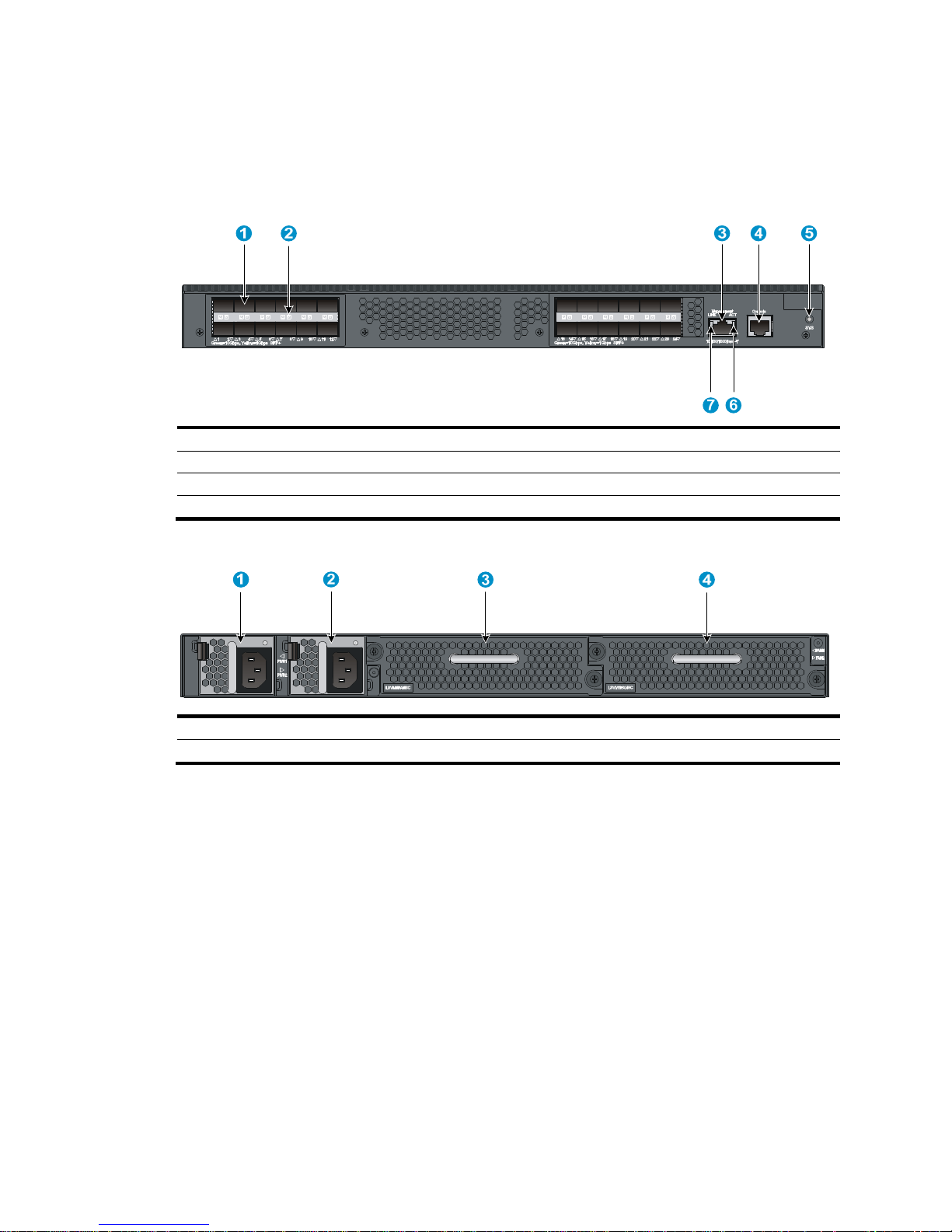
Figure 2 HP 5920AF-24XG/HP 5920AF-24XG TAA rear panel
(1) Power supply slot 1 (2) Power supply slot 2
(3) Fan tray slot 1
(4) Fan tray slot 2
The HP 5920AF-24XG and 5920AF-24XG TAA switches come with the power supply slots empty and the
filler modules for the slots as accessories. You can install one or two power supplies for the switch as
needed. In this figure, two 650W AC power supplies are installed. For more information about installing
and removing the power supply, see "Installing/removing a power supply."
T
he HP 5920AF-24XG and 5920AF-24XG TAA switches also come with the fan tray slots empty. You must
install two fan trays for the 5920AF-24XG and 5920AF-24XG TAA for adequate heat dissipation, and
their models must be the same. In this figure, two LSVM1FANSC fan trays are installed. For more
information about installing and removing the fan tray, see "Installing/removing a fan tray."
3
Figure 3 HP 5920AF-24XG/HP 5920AF-24XG TAA left side panel
(1) Primary grounding point (2) Auxiliary grounding point 1
HP 5900AF-48XG-4QSFP+/HP
5900AF-48XG-4QSFP+ TAA panel views
Figure 4 HP 5900AF-48XG-4QSFP+/HP 5900AF-48XG-4QSFP+ TAA front panel
(1) SFP+ port (2) SFP+ port LED
(3) QSFP+ port (4) QSFP+ port LED
(5) System status LED (SYS)
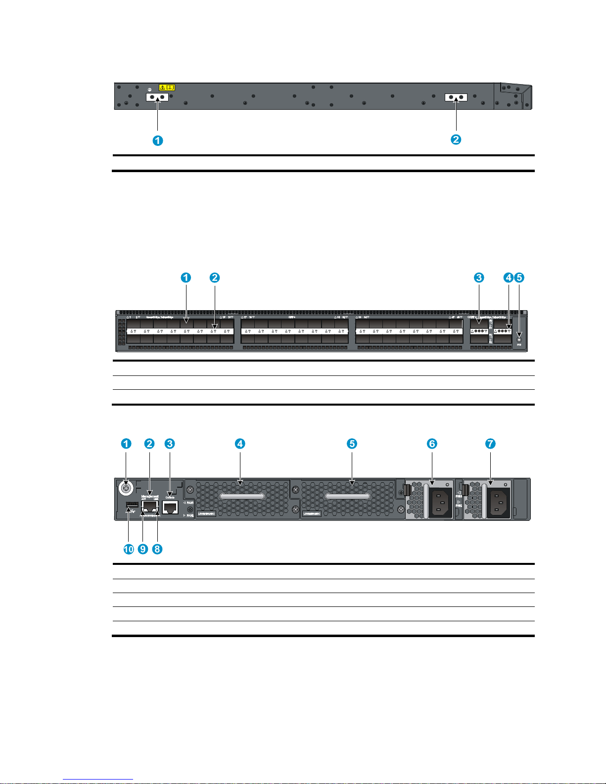
Figure 5 HP 5900AF-48XG-4QSFP+/HP 5900AF-48XG-4QSFP+ TAA rear panel
(1) Grounding screw (auxiliary grounding point 2) (2) Management Ethernet port
(3) Console port (4) Fan tray slot 1
(5) Fan tray slot 2
(6) Power supply slot 1
(7) Power supply slot 2 (8) LINK LED for the management Ethernet port
(9) ACT LED for the management Ethernet port
(10) USB port
The HP 5900AF-48XG-4QSFP+ and 5900AF-48XG-4QSFP+ TAA switches come with the power supply
slots empty and the filler modules for the slots as accessories. You can install one or two power supplies
for the switch as needed. In this figure, two 650W AC power supplies are installed. For more information
about installing and removing the power supply, see "Installing/removing a power supply."
4
The HP 5900AF-48XG-4QSFP+ and 5900AF-48XG-4QSFP+ TAA switches also come with the fan tray
slots empty. You must install two fan trays for the 5900AF-48XG-4QSFP+ and 5900AF-48XG-4QSFP+
TAA for adequate heat dissipation, and their models must be the same. In this figure, two LSWM1FANSC
fan trays are installed. For more information about installing and removing the fan tray, see
"Installing/removing a fan tray."
Figure 6 H
P 5900AF-48XG-4QSFP+/HP 5900AF-48XG-4QSFP+ TAA left side panel
(1) Primary grounding point (2) Auxiliary grounding point 1
HP 5900AF-48XGT-4QSFP+ panel views
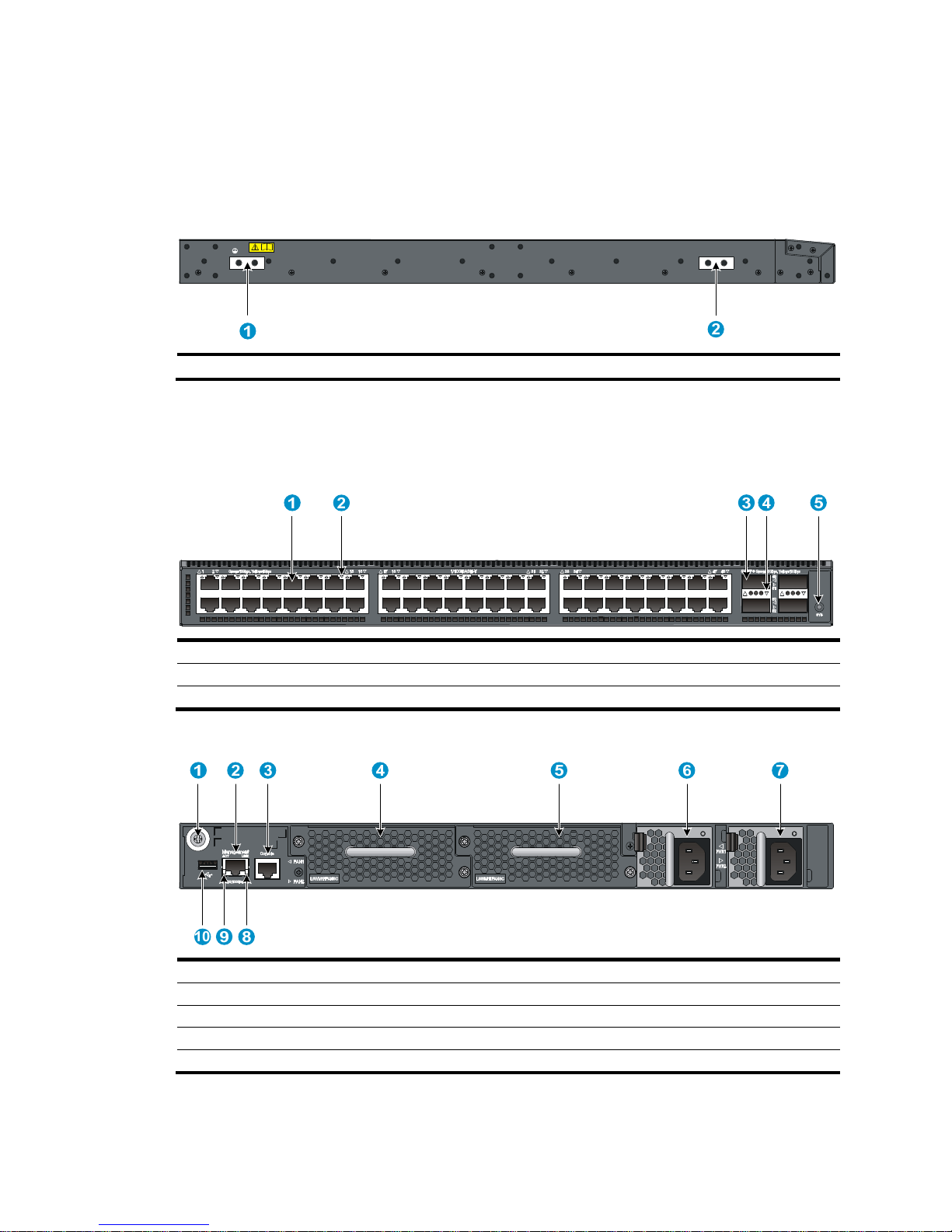
Figure 7 HP 5900AF-48XGT-4QSFP+ front panel
(1) 1/10GBase-T autosensing Ethernet port (2) 1/10GBase-T autosensing Ethernet port LED
(3) QSFP+ port (4) QSFP+ port LED
(5) System status LED (SYS)
Figure 8 HP 5900AF-48XGT-4QSFP+ rear panel
(1) Grounding screw (auxiliary grounding point 2)
(2) Management Ethernet port
(3) Console port (4) Fan tray slot 1
(5) Fan tray slot 2
(6) Power module slot 1
(7) Power module slot 2 (8) LINK LED for the management Ethernet port
(9) ACT LED for the management Ethernet port (10) USB port
The HP 5900AF-48XGT-4QSFP+ switch comes with the power supply slots empty and the filler modules
for the slots as accessories. You can install one or two power supplies for the switch as needed. In Figure
5
11, two LSVM1AC650 power supplies are installed. For more information about installing and removing
the power supply, see "Installing/removing a power supply."
The HP 5900AF-48XGT-4QSFP+ switch also comes with the fan tray slots empty. You must install two fan
trays for the 5900AF-48XGT-4QSFP+ for adequate heat dissipation, and their models must be the same.
In Figure 11, t
wo LSWM1HFANSC fan trays are installed. For more information about installing and
removing the fan tray, see "Installing/removing a fan tray."
Figure 9 H
P 5900AF-48XGT-4QSFP+ left side panel
(1) Primary grounding point (2) Auxiliary grounding point 1
HP 5900AF-48G-4XG-2QSFP+ panel views
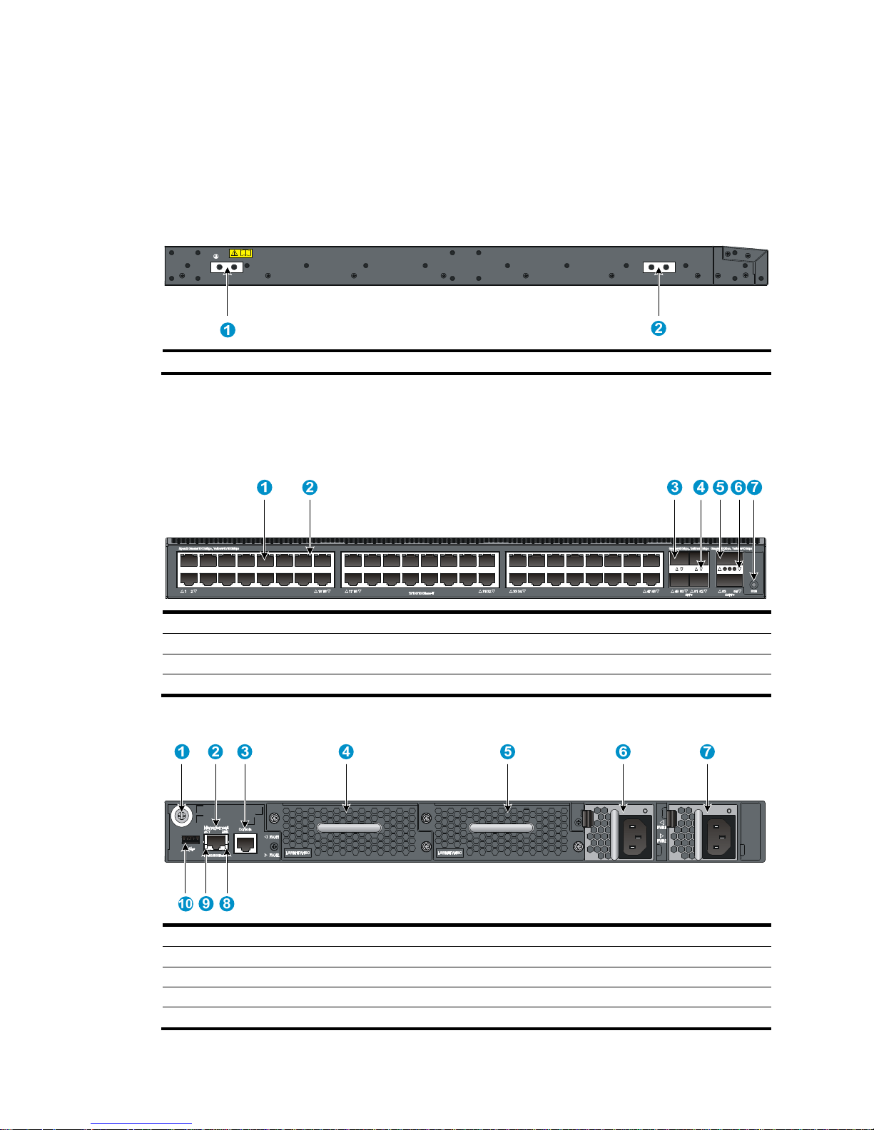
Figure 10 HP 5900AF-48G-4XG-2QSFP+ front panel
(1) 10/100/1000Base-T autosensing Ethernet port (2) 10/100/1000Base-T autosensing Ethernet port LED
(3) SFP+ port (4) SFP+ port LED
(5) QSFP+ port (6) QSFP+ port LED
(7) System status LED (SYS)
Figure 11 HP 5900AF-48G-4XG-2QSFP+ rear panel
(1) Grounding screw (auxiliary grounding point 2)
(2) Management Ethernet port
(3) Console port (4) Fan tray slot 1
(5) Fan tray slot 2 (6) Power supply slot 1
(7) Power supply slot 2 (8) LINK LED for the management Ethernet port
(9) ACT LED for the management Ethernet port
(10) USB port
6
The HP 5900AF-48G-4XG-2QSFP+ switch comes with the power supply slots empty and the filler
modules for the slots as accessories. You can install one or two power supplies for the switch as needed.
In Figure 11, t
wo LSVM1AC650 power supplies are installed. For more information about installing and
removing the power supply, see "Installing/removing a power supply."
The HP 5900AF-48G-4XG-2QSFP+ switch also comes with the fan tray slots empty. You must install two
fan trays for the 5900AF-48G-4XG-2QSFP+ for adequate heat dissipation, and their models must be the
same. In Figure 11, t
wo LSWM1FANSC fan trays are installed. For more information about installing and
removing the fan tray, see "Installing/removing a fan tray."
Figure 12 H
P 5900AF-48G-4XG-2QSFP+ left side panel
(1) Primary grounding point (2) Auxiliary grounding point 1

7
Preparing for installation
Safety recommendations
To avoid any equipment damage or bodily injury caused by improper use, read the following safety
recommendations before installation. Note that the recommendations do not cover every possible
hazardous condition.
• Before cleaning the switch, unplug all power cords from the switch. Do not clean the switch with wet
cloth or liquid.
• Do not place the switch near water or in a damp environment. Prevent water or moisture from
entering the switch chassis.
• Do not place the switch on an unstable case or desk. The switch might be severely damaged in case
of a fall.
• Ensure proper ventilation of the equipment room and keep the air inlet and outlet vents of the switch
free of obstruction.
• Connect the yellow-green protection grounding cable before power-on.
• Make sure the operating voltage is in the required range.
• To avoid electrical shocks, do not open the chassis while the switch is operating or when the switch
is just powered off.
• When replacing FRUs, including power supplies and fan trays, wear an ESD-preventive wrist strap
to avoid damaging the units.
Examining the installation site
The HP 5920 and 5900 switches must be used indoors.
Mount your switch in a rack and make sure:
• Adequate clearance is reserved at the air inlet and exhaust vents for ventilation.
• The rack has a good ventilation system.
• Identify the hot aisle and cold aisle at the installation site, and make sure ambient air flows into the
switch from the cold aisle and exhausts to the hot aisle.
• Identify the airflow designs of neighboring devices, and prevent hot air flowing out of the bottom
device from entering the top device.
• The rack is sturdy enough to support the switch and its accessories.
• The rack is well earthed.
To ensure normal operation and long service life of your switch, install it in an environment that meets the
requirements described in the following subsections.
Temperature/humidity
Maintain appropriate temperature and humidity in the equipment room.

8
• Lasting high relative humidity can cause poor insulation, electricity creepage, mechanical property
change of materials, and metal corrosion.
• Lasting low relative humidity can cause washer contraction and ESD and bring problems including
loose captive screws and circuit failure.
• High temperature can accelerate the aging of insulation materials and significantly lower the
reliability and lifespan of the switch.
For the temperature and humidity requirements of different switch models, see "Appendix A Technical
spec
ifications."
Cleanness
Dust buildup on the chassis may result in electrostatic adsorption, which causes poor contact of metal
components and contact points, especially when indoor relative humidity is low. In the worst case,
electrostatic adsorption can cause communication failure.
Table 2 Dust concentration limit in the equipment room
Substance Concentration limit (particles/m³)
Dust
≤ 3 x 10⁴ (no visible dust on the tabletop over three days)
NOTE:
Dust diameter ≥ 5 μm
The equipment room must also meet strict limits on salts, acids, and sulfides to eliminate corrosion and
premature aging of components, as shown in Table 3.
Table 3 Harmful gas li
mits in the equipment room
Gas Maximum concentration (mg/m
3
)
SO
2
0.2
H2S 0.006
NH3 0.05
Cl2 0.01
EMI
All electromagnetic interference (EMI) sources, from outside or inside of the switch and application
system, adversely affect the switch in a conduction pattern of capacitance coupling, inductance coupling,
electromagnetic wave radiation, or common impedance (including the grounding system) coupling. To
prevent EMI, take the following actions:
• If AC power is used, use a single-phase three-wire power receptacle with protection earth (PE) to
filter interference from the power grid.
• Keep the switch far away from radio transmitting stations, radar stations, and high-frequency
devices.
• Use electromagnetic shielding, for example, shielded interface cables, when necessary.
• Route interface cables only indoors to prevent signal ports from getting damaged by overvoltage or
overcurrent caused by lightning strikes.

9
Laser safety
The HP 5920 and 5900 switches are Class 1 laser devices.
W
ARNING!
Do not stare into any fiber port when the switch has power. The laser li
g
ht emitted from the optical fiber
may hurt your eyes.
Installation tools
• Phillips screwdriver
• ESD-preventive wrist strap
All these installation tools are user supplied.
10
Installing the switch
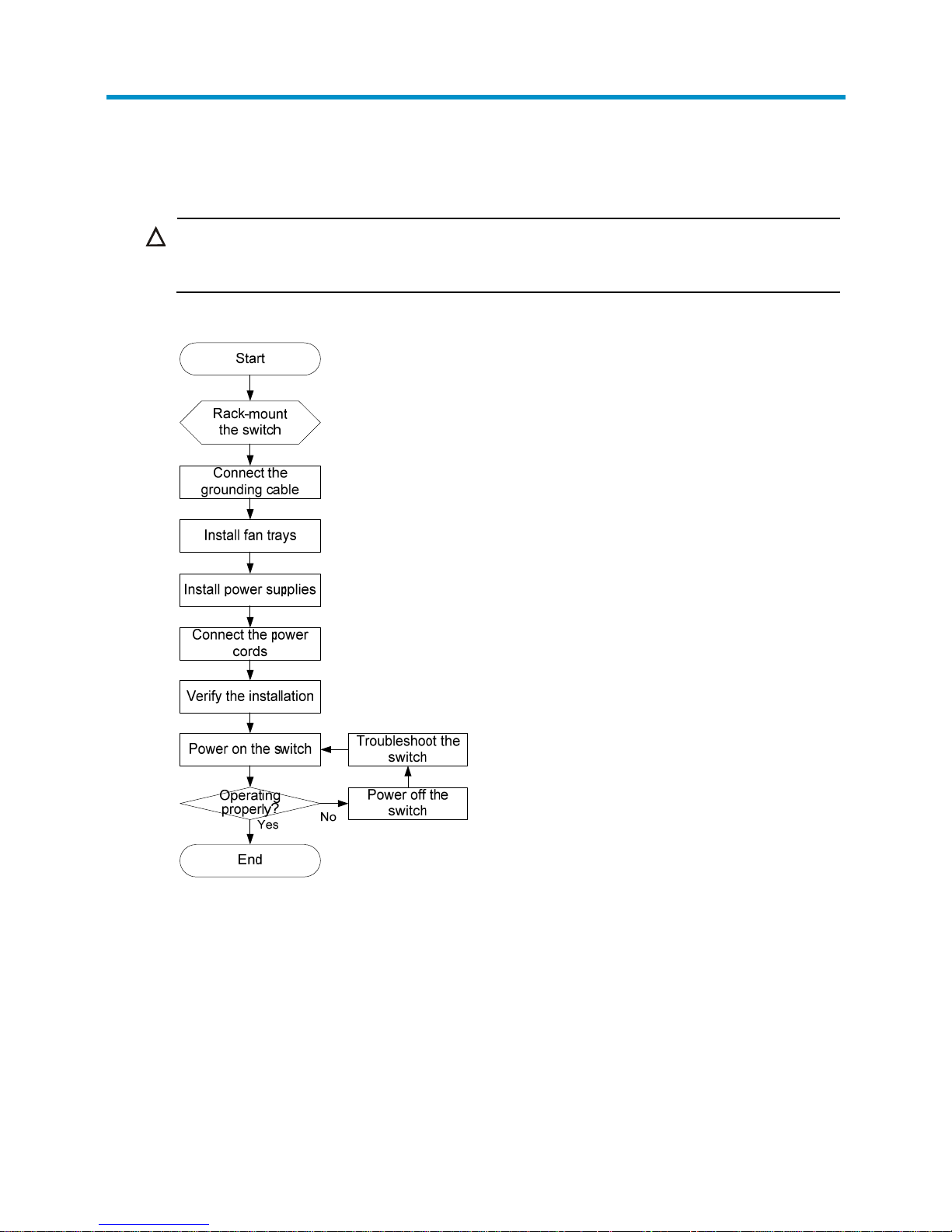
CAUTION:
Keep the tamper-proof seal on a mounting screw on the chassis cover intact, and if you want to open the
chassis, contact HP for permission. Otherwise, HP shall not be liable for any consequence caused thereby.
Figure 13 Hardware installation flow
Installing the switch in a 19-inch rack
Installation prerequisites
The rack depth for the HP 5920AF-24XG, 5920AF-24XG TAA, 5900AF- 48XGT-4QSFP+,
5900AF-48XG-4QSFP+, and 5900AF-48XG-4QSFP+ TAA switches must be 1000 mm (39.37 in).
11
Mounting bracket and rack mounting rail kits
Every HP 5920 and 5900 switch comes with a pair of mounting brackets and a pair of chassis rails and
a pair of slide rails. See Figure 14 and Figure 15.
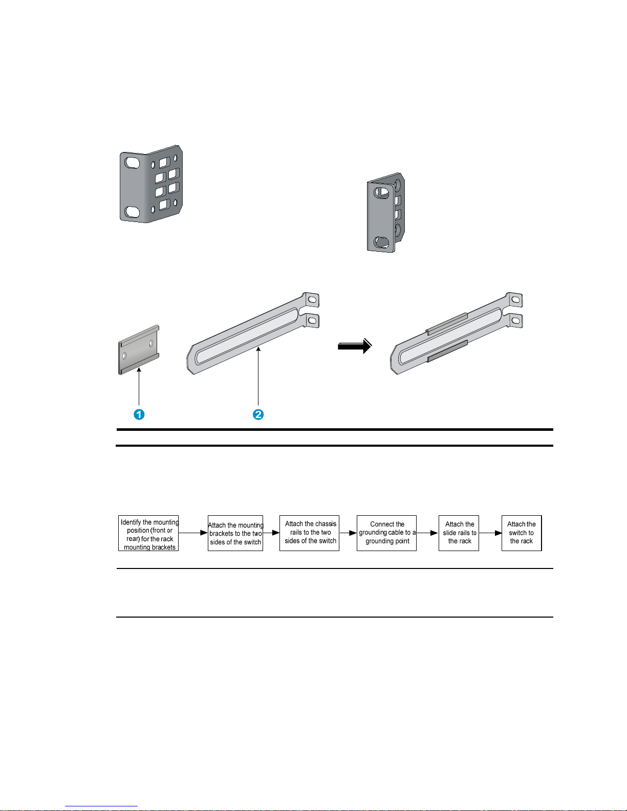
Figure 14 1U mounting
bracket kit
Figure 15 Rack mounting rail kit
(1) Chassis rail (2) Slide rail
Rack-mounting procedures at a glance
Figure 16 Rack-mounting procedure
NOTE:
If a rack shelf is available, you can put the switch on the rack shelf, slide the switch to an appropriate
location, and attach the switch to the rack with the mounting brackets.
Attaching the mounting brackets, chassis rails, and grounding
cable to the chassis
Each of the HP 5920 and 5900 switches has one front mounting position (near the network ports) and
one rear mounting position (near the power supplies).
12
Each of the HP 5920AF-24XG and 5920AF-24XG TAA switches has one primary grounding point (with
a grounding sign) and one auxiliary grounding point, and each of the HP 5900AF-48XG-4QSFP+,
5900AF-48XG-4QSFP+ TAA, 5900AF-48XGT-4QSFP+, and 5900AF-48G-4XG-2QSFP+ switches has
one primary grounding point (with a grounding sign) and two auxiliary grounding points. Use the
primary grounding point whenever possible. If the primary grounding point fails or is not suitable for the
installation site, use one of the auxiliary grounding points.
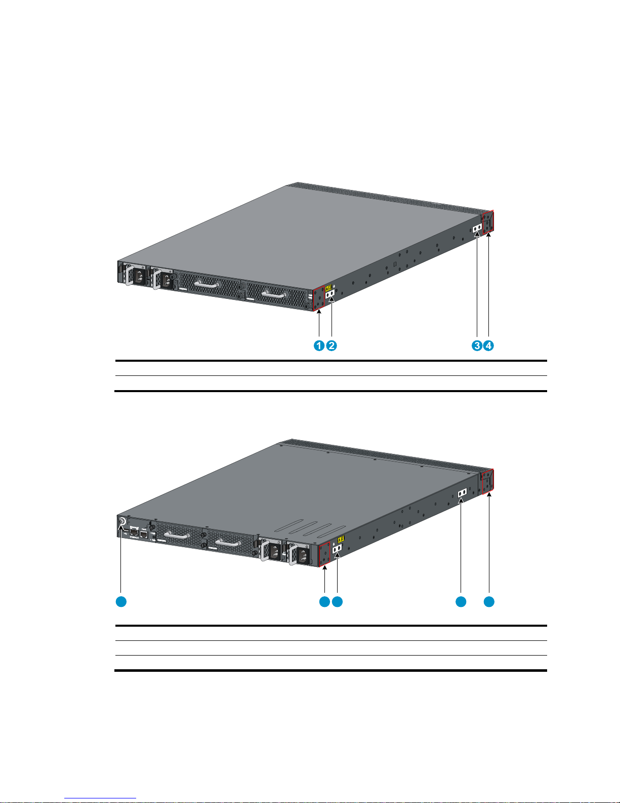
Figure 17 Identifying the mounting and grounding positions of the HP 5920AF-24XG/5920AF-24XG
TAA
(1) Rear mounting position (2) Primary grounding point
(3) Auxiliary grounding point 1 (4) Front mounting position
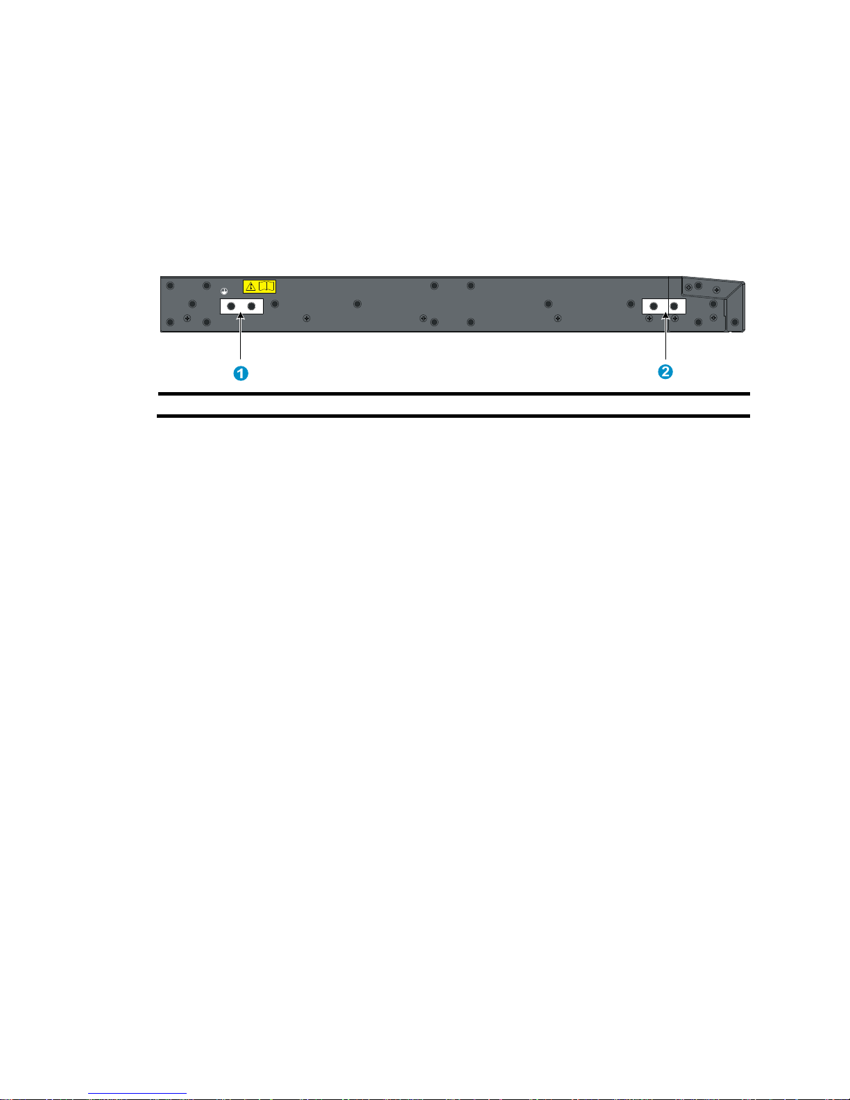
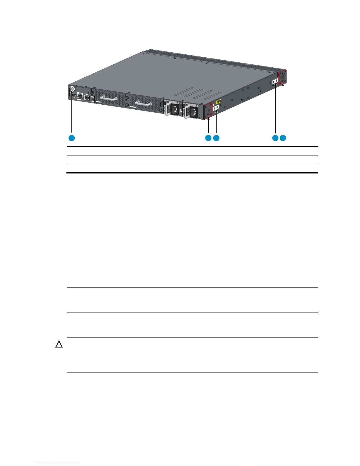
Figure 18 Identifying the mounting and grounding positions of the HP
5900AF-48XG-4QSFP+/5900AF-48XG-4QSFP+ TAA/5900AF-48XGT-4QSFP+
(1) Auxiliary grounding point 2 (2) Rear mounting position
(3) Primary grounding point (4) Auxiliary grounding point 1
(5) Front mounting position
1 2 3 4 5
13
Figure 19 Identifying the mounting and grounding positions of the HP 5900AF-48G-4XG-2QSFP+
(1) Auxiliary grounding point 2 (2) Rear mounting position
(3) Primary grounding point (4) Auxiliary grounding point 1
(5) Front mounting position
Attaching the mounting brackets and chassis rails to the chassis
To attach the mounting brackets and chassis rails to the switch chassis:
1. Align the mounting brackets with the screw holes in the rear mounting position or front mounting
position. See Figure 20 and Figure 21.
2. Use M4 screws (supplied with the switch) to attach the mounting brackets to the chassis.
3. Align the chassis rails with the rail mounting holes in the chassis:
{ If the mounting brackets are in the rear mounting position, align the chassis rails with the screw
holes at the front of the side panels. See Figure 20.
{ If the mounting brackets are in the front mounting position, align the chassis rails with the screw
holes at the rear of the side panels. See Figure 21.
4. Use M4 screws (supplied with the switch) to attach the chassis rails to the chassis.
NOTE:
Secure the mounting brackets and chassis rails to both sides of the chassis in the same way.
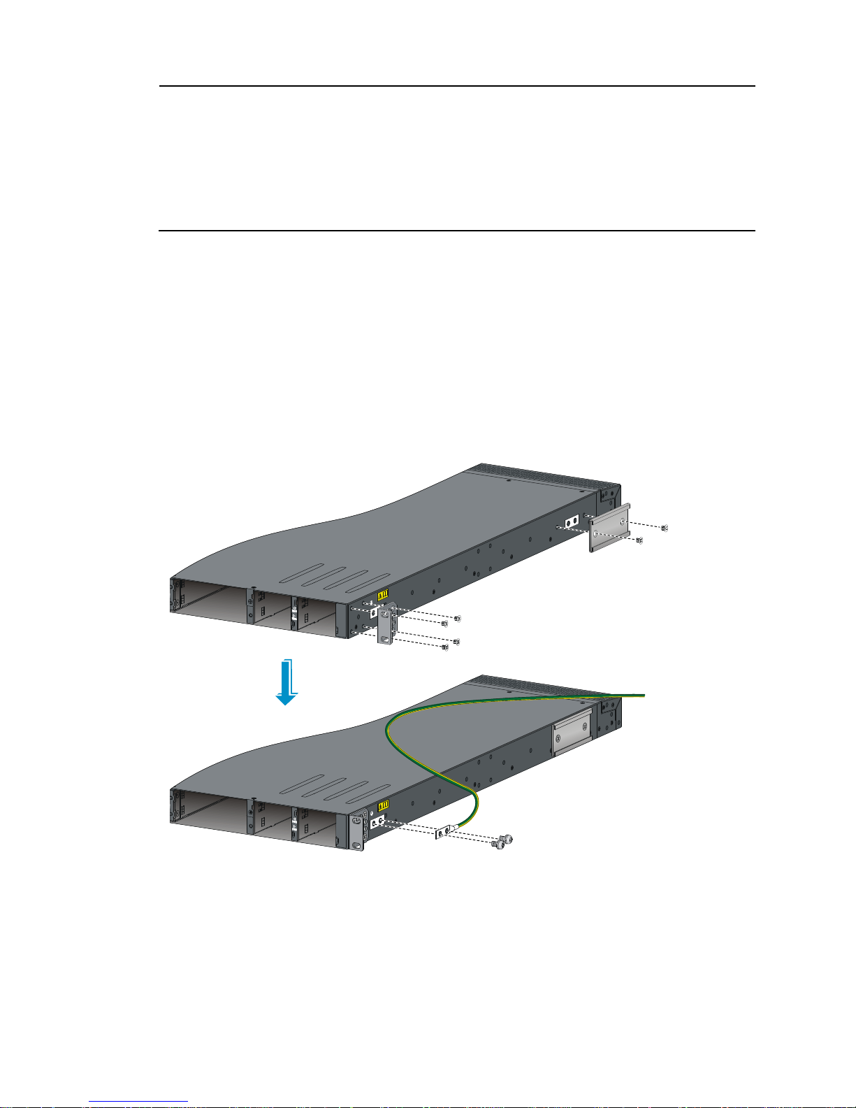
Connecting the grounding cable to the chassis
CAUTION:
The primary grounding point and auxiliary grounding point 1 are located on the left side panel. If you use
one of these grounding points, you must connect the grounding cable to the grounding point before you
mount the switch in the rack.
1
2
3
4 5
14
NOTE:
• HP recommends that you use the primary grounding point or auxiliary grounding point 1 because the
grounding cable and grounding screw that come with the switch are suitable only for these two
grounding points.
• To use auxiliary grounding point 2 on the HP 5900AF-48XG-4QSFP+, 5900AF-48XG-4QSFP+ TAA,
5900AF-48XGT-4QSFP+, and 5900AF-48G-4XG-2QSFP+ switches, you must prepare a grounding
cable yourself.
To connect the grounding cable to a chassis grounding point, for example, the primary grounding point:
1. Choose a grounding point.
2. Unpack the grounding cable and grounding screws.
You can use the cable and screws shipped with the switch only for connecting to the primary
grounding point or auxiliary grounding point 1.
3. Align the two-hole grounding lug at one end of the cable with the grounding holes of the
grounding point, insert the grounding screws into the holes, and tighten the screws with a
screwdriver to attach the grounding lug to the chassis, as shown in Figure 20.
Figure 20 Attaching th
e rear mounting brackets/chassis rails/grounding cable to the chassis
15
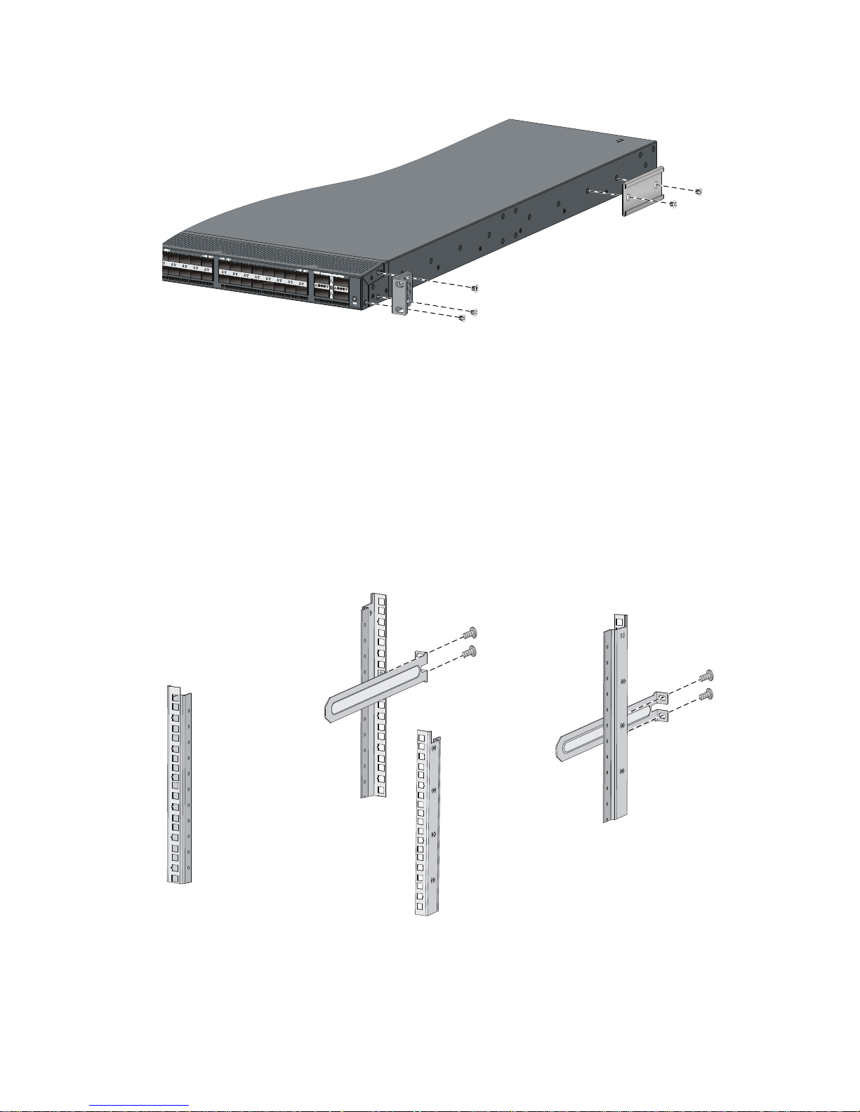
Figure 21 Attaching the front mounting brackets/chassis rails to the chassis
Attaching the slide rails to the rack
To attach the slide rails to the rack:
1. Identify the rack attachment position for the slide rails.
2. Install cage nuts (user-supplied) in the mounting holes in the rack posts.
3. Align the screw holes in one slide rail with the cage nuts in the rack post on one side, and use
screws (user supplied) to attach the slide rail to the rack, as shown in Figure 22.
4. Repeat the preceding step to attach the other slide rail to the rack post on the other side.
Keep the two slide rails at the same height so the slide rails can attach into the chassis rails.
Figure 22 Installing the slide rails
Mounting the switch in the rack
This task requires two people. To mount the switch in the rack:
 Loading...