

Page 1

Reference Manual
HP 5890 Series II and
HP 5890 Series II Plus
Page 2

D
Hewlett-Packard
Company 1989,1990, 1991,
1993, 1994
All Rights Reserved.
Reproduction, adaptation,
or translation without
permission is prohibited,
except as allowed under
the copyright laws.
HP part number
05890-90271
First edition—Jun 1989
Printed In U.S.A.
Second edition—Oct 1989
Printed In U.S.A.
Third edition—Jan 1990
Printed In U.S.A.
Fourth edition—Oct 1990
Printed In U.S.A.
Fifth edition—Oct 1991
Printed In U.S.A.
Fifth edition—Mar 1993
Printed In U.S.A.
Sixth edition—Jul 1994
Printed In U.S.A.
Printed in USA
Warranty
The information contained
in this document is subject
to change without notice.
Hewlett-Packard makes no
warranty of any kind with
regard to this material,
including, but not limited
to, the implied warranties
of merchantability and
fitness for a particular
purpose. Hewlett-Packard
shall not be liable for errors
contained herein or for
incidental or consequential
damages in connection with
the furnishing,
performance, or use of this
material.
Safety Information
The HP 5890 Series II and
HP 5890 Series II Plus are
IEC (International
Electrotechnical
Commission) Safety Class 1
instruments. This unit has
been designed and tested in
accordance with recognized
safety standards. Whenever
the safety protection of the
HP 5890 Series II has been
compromised, disconnect
the unit from all power
sources and secure the unit
against unintended
operation.
Safety Symbols
This manual contains
safety information that
should be followed by the
user to ensure safe
operation.
WARNING
A warning calls attention
to a condition or possible
situation that could cause
injury to the user.
CAUTION
A caution calls attention to
a condition or possible
situation that could
damage or destroy the
product or the user’s work.
Important User
Information for In Vitro
Diagnostic Applications
This is a multipurpose
product that may be used
for qualitative or
quantitative analyses in
many applications. If used
in conjunction with proven
procedures (methodology)
by qualifiedoperator, one
of these applications may
be In Vitro Diagnostic
Procedures.
Generalized instrument
performance characteristics
and instructions are
included in this manual.
Specific In Vitro Diagnostic
procedures and
methodology remain the
choice and the
responsibility of the user,
and are not included.
Sound Emission
Certification for Federal
Republic of Germany
If Test and Measurement
Equipment is operated with
unscreened cables and/or
used for measurements in
open set-ups, users have to
assure that under these
operating conditions the
Radio Interference Limits
are still met at the border
of their premises.
The following information
is provided to comply with
the requirements of the
German Sound Emission
Directive dated January 18,
1991
Sound pressure Lp <
70db(A)
During normal operation
At the operator position
According to ISO 7779
(Type Test)
When operating the HP
5890 Series II with cryo
valve option, the sound
pressure
cryo valve operation for
short burst pulses.
78 db(A) during
Schallemission
Werden Meß- und
Testgeräte mit
ungeschirmten Kabeln
und/oder in offenen
Meßaufbauten verwendet,
so ist vom Betreiber
sicherzustellen, daß die
Funk-Entströbedingungen
unter Betriebsbedingungen
an seiner
Grundstücksgrenze
eingehalten werden.
Diese Information steht im
Zusammenhang mit den
Anforderungen der
Maschinenl
sverordnung vom 18
Januar 1991.
Schalldruckpegel LP < 70
dB(A)
Am Arbeitsplatz
Normaler Betrieb
Nach DIN 45635 T. 19
(Typpr
Bei Betrieb des HP 5890
Serie II mit Cryo Ventil
Option treten beim Oeffnen
des Ventils impulsfoermig
Schalldrucke Lp bis ca. 78
dB(A) auf.
ärminformation
üfung)
Little Falls Site
Page 3

Contents
Chapter 1 — Columns and Fittings 9.................
Column oven 11..........................................................
Column placement 12.................................................
Packed column 12....................................................
Hewlett•Packardcapillary columns 13..................................
Fittings 14...............................................................
Liners/adapters and inserts, general 17....................................
Inlet/detector liners/adapters 20...........................................
Packed column inlet liners 20..........................................
Detector liners/adapters 22............................................
ECD and TCD adapters 23............................................
Liner/adapter installation 24..........................................
Inlet inserts 25...........................................................
Packed column inlet inserts 25.........................................
Split/splitlessor split•onlycapillary inlet inserts 27......................
Jet replacement, FIDs or NPDs 30.........................................
Metal capillary columns 30................................................
Chapter 2 — Keyboard and Displays 31...............
Displaying setpoints 33...................................................
Entering setpoints 34.....................................................
Keyboard operation, INET control 37......................................
Protecting setpoints 38...................................................
Loading default setpoints 39..............................................
Chapter 3 — Temperature Control 43.................
Valid setpoint ranges 46..................................................
Cryogenic (sub•ambient)oven control 47...................................
Programming oven temperature 49........................................
Oven status 50...........................................................
Oven safety 51...........................................................
Fault: messages 52.......................................................
After a power failure . . . 53...............................................
Oven temperature calibration 54..........................................
Page 4

Contents
Chapter 4 — Electronic Flow Sensing 57...............
Displaying gas flow rate 58...............................................
Designating gas type 59..................................................
Electronic flow sensor (EFS) calibration 60.................................
Preparation 61.......................................................
Setting the zero calibration value 61...................................
Setting the GAIN calibration value 63..................................
Entering specific ZERO and GAIN values 65............................
Chapter 5 — Signal Output 67........................
Zeroing signal output 68..................................................
Displaying current setpoint 69........................................
Self• setpoint 70......................................................
User•defined setpoint 72..............................................
Signal attenuation 72.....................................................
Displaying current
RANGE 2!()
Entering / setpoints 76..............................................
Switching off the +1 mV output 76.....................................
Test signal output 77.....................................................
Instrument network (INET) 79............................................
The controller 79.....................................................
An instrument 81.....................................................
Active workspace 82..................................................
HP 5890 INET states 82...............................................
INET operation 83....................................................
Automatic INET reconfiguration 85....................................
INET configuration 85....................................................
Switching between Global and Local 86.................................
INET/HP•ILaddresses 87.............................................
HP•ILloopback test 90...................................................
Warn: and fault: messages 92.............................................
File compatibility with data handling devices 94............................
What are the modes? 94...............................................
What is the proper mode for my data handling device? 94................
How do I know in which mode my GC is configured now? 94..............
How do I change modes? 95............................................
How to convert HP 339X Integrator workfiles from 5890A
to SERIES II mode: 97.............................................
ATTN 2!()
/
setpoints 75..............
Page 5

Contents
Chapter 6 — Inlet Systems 99.........................
Packed column inlet 100...................................................
Electronic flow sensor 102..............................................
Septum•purgedpacked column inlet 103.................................
Problems at high inlet temperatures 104.................................
A thermally optimized high•temperatureinlet 104........................
Septum purge 105.....................................................
Electronic flow sensor 106..............................................
Split/splitlesscapillary inlet 107............................................
Carrier gas considerations 108..........................................
Initial column head pressure 110........................................
Split sampling 111.....................................................
Splitless sampling 114.................................................
Injection technique, split/splitless sampling 121..........................
Chapter 7 — Detector Systems 123.....................
Capillary makeup gas flow rate 124.........................................
FID and NPD jets 125.....................................................
Flame ionization detector (FID) 126.........................................
FID flameout problems 128.............................................
Nitrogen•phosphorusdetector (NPD) 129....................................
Performance considerations 132.........................................
Electron capture detector (ECD) 135........................................
Requirements for USA owners 135......................................
Temperature 140......................................................
Background level 141..................................................
Thermal conductivity detector (TCD) 143....................................
Optimizing performance 146............................................
Analyzing for hydrogen, special considerations 148.......................
TCD•to•FIDseries connection 149.......................................
Filament passivation 149...............................................
Capillary column considerations 150....................................
Flame photometric detector (FPD) 151......................................
Optimizing FPD sensitivity and selectivity 151...........................
Flame ignition problems 153............................................
Page 6

Contents
Chapter 8 — Preventive Maintenance 155..............
Conditioning columns 156..................................................
(Re)Packing columns 158..................................................
Packed column inlet 159...................................................
Changing septa 159....................................................
Insert/liner care 160...................................................
Leaks 160.............................................................
Cleaning 162..........................................................
Split/splitlesscapillary inlets 163...........................................
Changing septa 163....................................................
Insert care 164........................................................
Leaks 165.............................................................
Cleaning 168..........................................................
Liner and/or insert care 169................................................
Glass inserts 169......................................................
Repacking a split insert 170............................................
Metal inserts and/or liners 171..........................................
Flame ionization detector (FID) 171.........................................
Jet exchange/replacement 172..........................................
Cleaning 173..........................................................
Ignition problems 177..................................................
Nitrogen•phosphorusdetector (NPD) 178....................................
Cleaning 178..........................................................
Removing/replacing the NPD collector 181...............................
Type B NPD transformer/collector assembly 184..........................
Reinstallation 186.....................................................
Electron capture detector (ECD) 188........................................
Frequency test 188....................................................
Carrier gas evaluation 188.............................................
Leaks 189.............................................................
Thermal cleaning 190..................................................
Packed column: 191....................................................
Capillary column: 191..................................................
Radioactivity leak test (wipe test) 192...................................
Thermal conductivity detector (TCD) 192....................................
Cleaning 192..........................................................
Flame photometric detector 193............................................
Cleaning/replacing FPD windows, filters, seals 193.......................
Cleaning/replacing the FPD jet 197.....................................
FPD leak testing (GC with electronic flow sensor) 198....................
FPD leak testing (GC without electronic flow sensor) 199.................
Conditioning chemical traps 200............................................
Page 7

Contents
Chapter 9 — Chromatographic Troubleshooting 201......
Introduction 202..........................................................
Baseline symptoms 202....................................................
Position 202...........................................................
Wander and drift 203..................................................
Noise 204.............................................................
Spiking 206...........................................................
Retention time symptoms 207..............................................
Retention time drift 207................................................
Retention time wander (reproducibility) 207.............................
Peak symptoms 209.......................................................
No peaks 209..........................................................
Inverted peaks 209....................................................
Extra peaks 209.......................................................
Deformed peaks 211...................................................
Troubleshooting valve systems 214..........................................
Chromatographic symptoms 214........................................
Locating leaks 216........................................................
Pressure check 217........................................................
Electronic pressure control 218.............................................
Safety shutdown 219...................................................
Proper configuration 220...............................................
Switch setting examples 221............................................
Chapter 10 — Test Sample Chromatograms 223........
Test sample chromatograms 225............................................
Index 241.............................................
Page 8

This page intentionally left blank.
Page 9

1
Columns and Fittings
Page 10

Columns and Fittings
The HP 5890 SERIES II (hereafter referred to as HP 5890) provides
flexibility in choices among inlets, columns, and detectors through use of
liners and adapters, allowing any standard column to be used without
sacrificing performance. Additionalflexibility is gained through positions
of inlets and detectors relative to each other and through the large
internal volume of the oven.
This section provides information for the following:
C
The column oven.
C
Fittings.
C
Liners and inserts.
C
ECD and TCD capillary makeup gas adapters.
The first three items must be considered before a column may be
installed properly at either an inlet or a detector. In addition, for an FID
or NPD, and depending upon the column to be installed (packed versus
capillary), the correct jet must be installed before installing the column.
Jet installation is described in Chapter 8, Preventive Maintenance.
10
For specific information on ordering fittings, liners, and inserts, see
Hewlett•Packard's analytical supplies catalog.
Page 11
Columns and Fittings
Column oven
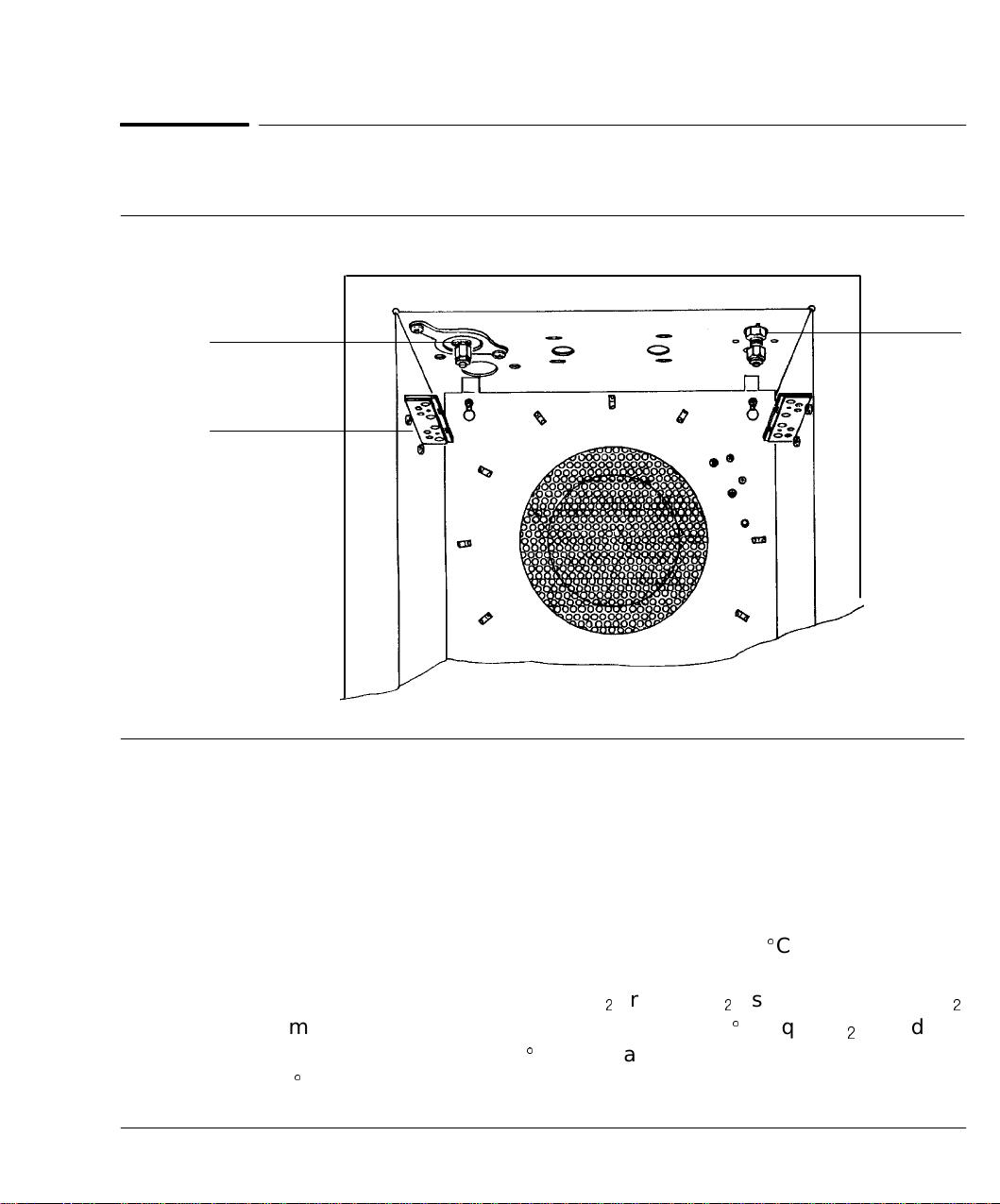
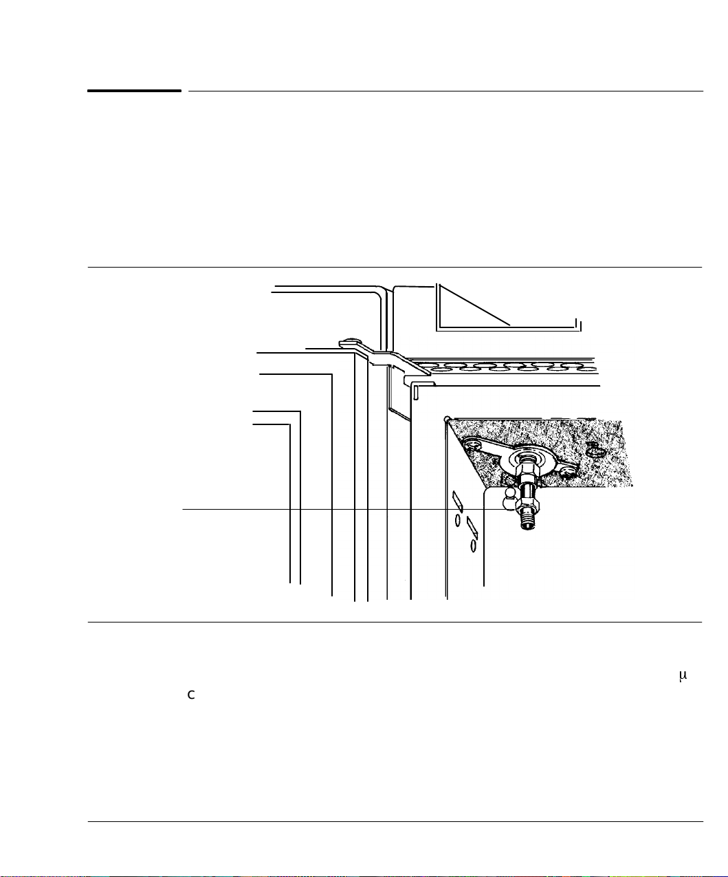
Column oven
Figure 1-1
Inlet Ftg
Nut Plate
The Column Oven
The oven door latch, located beneath the lower right corner of the door, is
pressed upward to open the door.
Motor•drivenflapsat the rear of the oven admit room air for cool down or
near•ambientoperation, so the door is kept closed except for access to
columns (the oven cools most efficiently with its door closed).
Det Ftg
The oven can maintain temperature down to about 7
^
C above ambient
without auxiliary cooling. If lower temperatures are required, a
cryogenic valve (for either liquid CO
1
or liquid N1) is needed. Liquid CO
permits reliable temperature control down to -50^C; liquid N1provides
reliable control down to -80
450
^
C.
^
C. The maximum oven temperature is
1
11
Page 12
Columns and Fittings
Column oven
Column placement
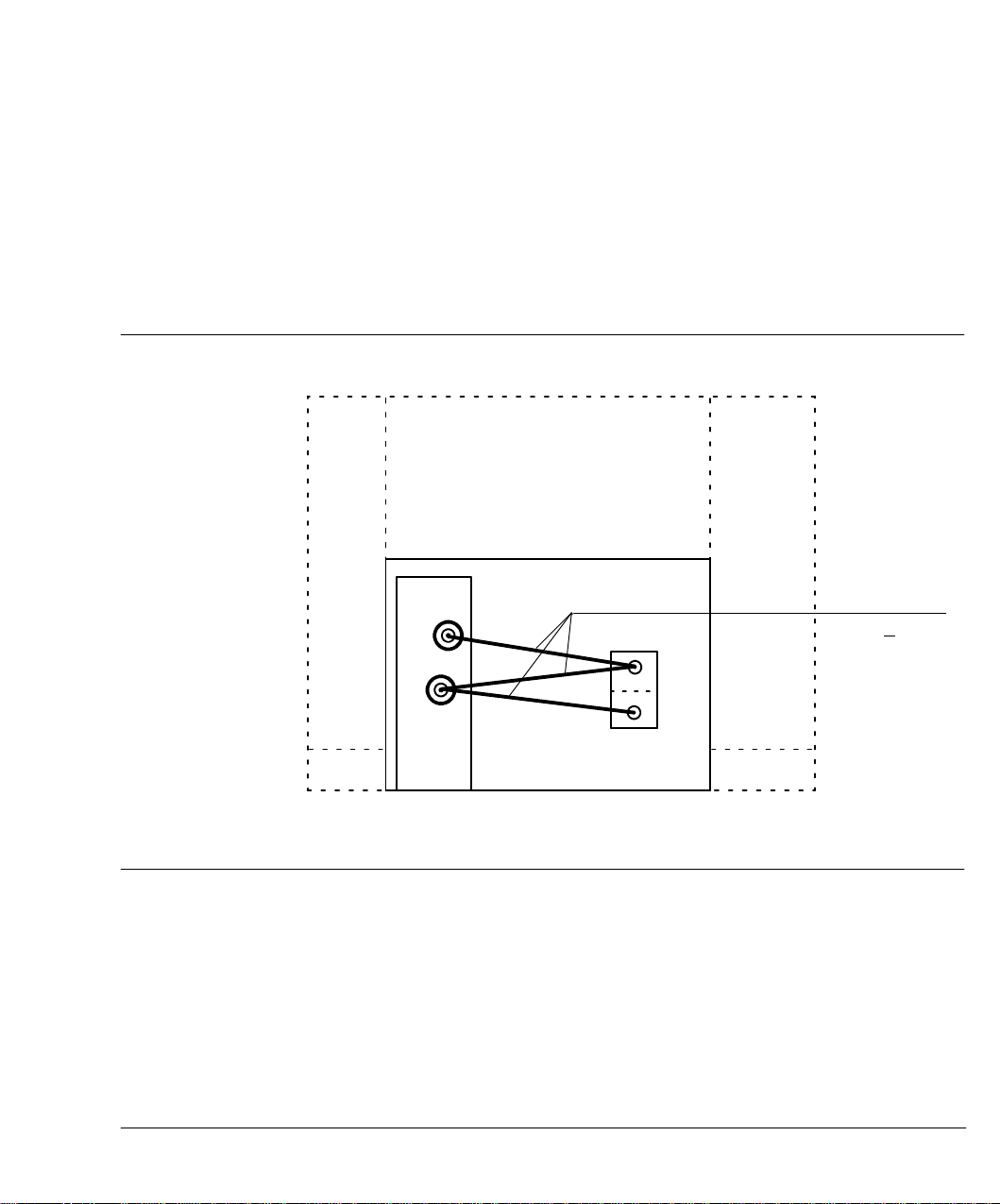
Generally, a column may be installed between any inlet and detector.
A rigid1/4•inchpacked glass column, however, if installed in the B
(rear•most)inlet, can only be installed in the B (rear•most)detector.
Distance relationships among inlets and detectors are shown in
Figure 1•2.
Figure 1-2
Top View
(showing relationshipof inlets to detectors)
B
A
Front
Installation Restrictions, Rigid Columns
1mm
228 +
B
A
12
Packed column
Packed columns require no physical support other than that provided by
proper installation at inlet and detector fittings.
Page 13
Columns and Fittings
Column oven
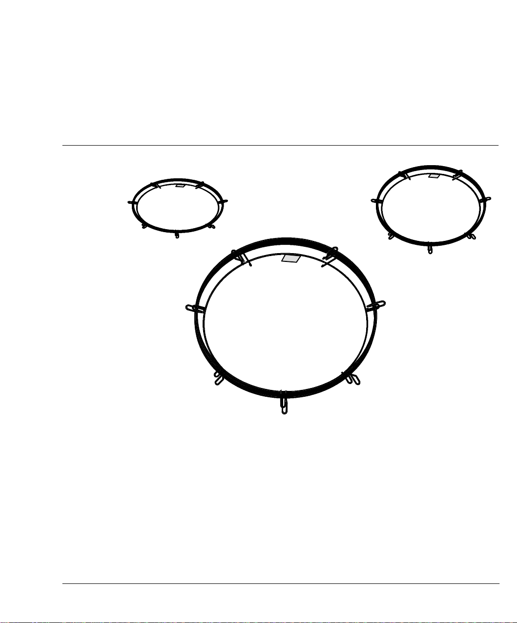
Hewlett-Packard capillary columns
Hewlett•Packardcapillary columns are wound on wire frames which
mount on a pair of brackets which slip into slots at the top of the oven
interior.
Figure 1-3
Typical Hewlett-Packard Capillary Columns
13
Page 14
Columns and Fittings
Fittings
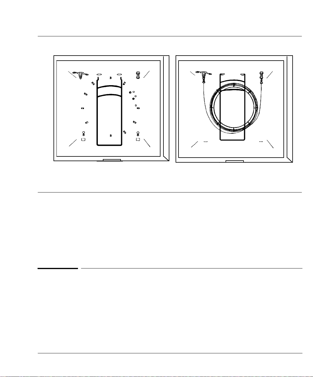
Figure 1-4.
Column Hanger
Part No. 1460-1914
Installed Bracket for Hewlett-Packard Capillary Columns
Column Installed
The bracket has two positions from which to hang the column wire frame.
Depending upon frame diameter, use the position which best centers the
column in the oven. Column ends should come off the bottom of the
frame, making smooth curves to inlet and detector fittings. Avoid
allowing any section of the column itself to come in contact with oven
interior surfaces.
Fittings
The following is a brief comparison of common types of fittings (nuts,
ferrules, O•rings)used to install columns, and to install inlet and detector
liners and/or inserts. Each type has its own set of advantages and
disadvantages:
14
Page 15

Columns and Fittings
Fittings
C
C
C
Graphite O•ringsor ferrules have excellent sealing quality and long
service life, can be used continuously to 400
^
C, and are generally
recommended for most applications, particularly capillary and glass
columns. They are also recommended for inlet and detector liners, and
for split/splitlesscapillary inlet inserts.
Since they do not adhere permanently to glass or metal, they can be
removed easily without damage to the column, tubing, liner, or insert.
A rear metal ferrule may be needed if recommended by the
manufacturer.
Commonly used with metal columns and tubing, brass nuts and
ferrules on the column prevent damage to inlet and detector liners,
but may develop leaks above 250
^
C or with temperature
programming.
Also commonly used with metal columns and tubing, stainless steel
fittings minimize possibility of leakage at high temperature, but
require care in installing columns; overtightening may damage the
column end or inlet/detector fitting.
C
Teflon ferrules may be used to 250^C but are recommended only for
isothermal work, because they develop leaks when
temperature•programmed.
C
Commonly used with glass columns, Vespel (or graphite•filledVespel)
ferrules are reusable and work well to 350
^
C. These ferrules may
leak or crack if tightened when cold.
C
Glass columns can be installed using silicone O•rings. For O•ring
installation, a back metal ferrule, reversed, is necessary to provide a
flat surface to seal against.
Silicone O•ringsare useful to about 250
^
C, but, due to bleed, interfere
in high•sensitivitywork. They also gradually lose elasticity and crack,
so they must be replaced fairly often.
15
Page 16

Columns and Fittings
Fittings
Table 1-1. Typical Fittings for Columns and Inlet/Detector Liners, Adapters, and Inserts
Type Description Typical Use Part No.
1/4-inch swage, nut 1/4-inch packed metal columns 5080-8753
stainless steel, front ferrule
pkg, 20 of each back ferrule
1/8-inch swage, nut 1/8-inch packed metal columns 5080-8751
stainless steel, front ferrule
pkg, 20 of each back ferrule
1/4-inch swage, nut 1/4-inch packed metal columns 5080-8752
brass, pkg, front ferrule
20 of each back ferrule
1/8-inch swage, nut 1/8-inch packed metal columns 5080-8750
brass, pkg, front ferrule
20 of each back ferrule
Vespel, 1/4-inch ferrule inlet/detector liners, 5080-8774
pkg of 10 1/4-inch glass packed columns
Vespel, 1/8-inch ferrule metal columns 0100-1107
pkg of 10
graphite, 1.0-mm ferrule capillary columns 5080-8773
pkg of 10
graphite, 0.5-mm ferrule capillary columns 5080-8853
pkg of 10
graphite 6.35-mm O-ring inlet/detector liners, 0905-0767
1/4-inch glass packedcolumns,
split capillary inlet insert
graphite 6.52-mm O-ring splitless capillary inlet insert (use) 0905-1004
silicone 6.0-mm O-ring inlet/detector liners 0905-0322
1/4-inch glass packedcolumns,
split/splitless capillaryinlet inserts
silicone 1.0 mm O-ring capillary columns 0905-0759
Note: Dimensions given are id’s of the O-ring or ferrule.
16
Page 17

Columns and Fittings
Liners/adapters and inserts, general
Liners/adapters and inserts, general
A liner/adapter is installed from below, inside the oven; it serves both as
an adapter to mate the particular column to the inlet or detector and to
provide correct internal volume for proper operation.
Inserts are used with inlets only, and, when required, are installed from
above, at the top of the inlet; these are discussed specificallylater in this
section (see Inlet inserts).
In general, the analysis to be performed determines the column to be
used. The column then dictates hardware required for the inlet and
detector (liner, insert, adapter, jet (FID or NPD)).
Note:
C
A correctly designed 1/4•inchpacked glass column requires no liners
since the column ends themselves serve this purpose.
C
The appropriate liner/adapter, and insert if required, must be
installed prior to installing a column.
Tables 1•2and 1•3summarize hardware required for various
combinations of inlets, columns, and detectors.
17
Page 18

Columns and Fittings
Liners/adapters and inserts, general
Table 1-2. Hardware and Recommended Fittings for Packed Column Installation
Packed Columns
1/8-inch Metal 1/4-inch Metal 1/4-inch Glass
Recommended 1/8-inch 1/4-inch 1/4-inch swage-
Column Fittings swage-type nut swage-type nut type nut and
and ferrules
3
and ferrules
3
graphic ferrule or
silicone O-ring(s)
Packed Column 19243-80510
1
19243-80520
1
Inlet Liners or or
19243-80530
1
19243-80540
1
(requires glass insert) (requires glass insert)
FID/NPD
2
19231-80521
1
19231-80530
1
Liners/Adapters
TCD Liners/Adapters None 19302-80020
ECD Liner/Adapters 19301-80530
1
Use 1/4-inch swage-typenut and Vespel or graphite ferrule to install liner/adapter.
2
See Chapter8 for details regardingjet exchange(if necessary).
3
See information later in this chapter regarding proper installation of swage-type fittingson packed
metal columns.
1
None None
1
None
None
19302-80020
(may require
altering the
column)
1
18
Page 19

Columns and Fittings
Liners/adapters and inserts, general
Table 1-3. Hardware and Recommended Fittings for Capillary Column Installation
Capillary Columns
HP Series 530
¿
320¿m ID 200¿m ID Metal/
Glass
Recommended Capillary column Capillary column Same as 320¿m Same as
Column Fittings nut and 1.0-mm nut and 0.5-mm HP Series
graphite ferrule, or graphite or 530
¿
silicone O-ring(s) silicone O-ring(s)
Packed Column 19244-80540
1
Not Not Not
Inlet Liners (requires glass Recommended Recommended Recom-
insert) mended
Split/Splitless & 18740-60840 Same Same Same
Split-Only with graphiteor
Capillary Inlet silicone O-ring
Split Sampling
Split/Splitless 18740-80220 Same Same Same
Capillary Inlet with graphite or
Insert: Splitless silicone O-ring
Sampling
Programmable 19245-20580
3
19245-20520 19245-20510 19245-
On-Column 20550
Capillary Inlet
Insert
FID/NPD
2
19244-80550
1
Same Same Same
Liners/Adapters
TCD 18740-20950 19232-80550
1
Same Same
Liners/Adapters and
18740-20960
ECD 19244-805501,
3
3
19233-80530 Same Same
Liners/Adapters
1
Use 1/4-inch swage-typenut (if a nut is notsuppliedas part ofthe adapter) and graphite or Vespel ferrule to
install liner/adapter.
2
0.11-inch jet must beused; see Chapter8 for informationregarding jet exchange (if necessary).
3
Use only if detector is not configured with capillary makeupgas adapter. If makeup adapter is provided,it is
used instead (usually with makeup gas turnedoff).
19
Page 20
Columns and Fittings
Inlet/detector liners/adapters
Inlet/detector liners/adapters
Interchangeable stainless steel liners/adapters, installed from inside the
oven, are used with the packed column inlet, and with all detectors,
depending upon the column to be installed.
Packed column inlet liners
Figure 1-5
20
Liner
Installed Liner, Packed Column Inlet
Liners for the packed column inlet are available in three sizes: one for
1/8•inchcolumns, one for 1/4•inchcolumns, and one for HP Series 530
capillary columns.
¿
Page 21

Columns and Fittings
Inlet/detector liners/adapters
In addition, liners for the packed column inlet are available to accept
glass inserts (discussed later) for reduced reactivity, to trap nonvolatile
residues, or for use with an HP Series 530
C
No liner is used with 1/4•inchpacked glass columns. The long leg of
the column fits into the inlet body, replacing the liner. Packing and
glass wool plug must be below the tip of the needle for best results.
C
Metal columns are installed with a liner appropriate for the column
diameter.
C
If necessary, glass columns can be installed using a metal liner
(preferably those accepting a glass insert), but this is not
recommended. There may be problems with dead volume in
connections, and preventing contact of sample with metal surfaces.
¿
capillary column.
21
Page 22

Columns and Fittings
Inlet/detector liners/adapters
Detector liners/adapters
Figure 1-6
Liner/Adapter
22
Typical Installed Detector Liner/Adapter
Detectors require a liner/adapter to be installed when used with packed
metal columns (either 1/8•or 1/4•inch),and with any type of capillary
column. Normally, no liner is required with 1/4•inchpacked glass
columns, since the leg of the column itself serves as the liner.
For the FID or NPD, the correct detector jet must be installed prior to
installation of the liner. (If jets must be exchanged, see Chapter 8,
Preventive Maintenance.)
Page 23

Columns and Fittings
Inlet/detector liners/adapters
ECD and TCD adapters
A makeup gas adapter must be installed in the ECD or TCD base to
install a capillary column, and to augment carrier flow through the
column with additional gas flow needed for optimal detector operation.
The adapter must be removed for packed column applications.
In addition, to install an HP Series 530
¿
capillary column in an ECD or
TCD having no capillary makeup gas adapter, the following adapters are
used: Part No. 19244•80550for the ECD, and Part No. 18740•20950and
18740•20960for the TCD.
Finally, to use a 1/4•inchcolumn with the TCD (having a base designed
for 1/8•inchcolumns), a 1/8•to 1/4•inchadapter is required (Part No.
19302•80020). For the ECD (having a base designed for 1/4•inch
columns), to use a 1/8•inchcolumn, a 1/4•to 1/8•inchadapter is required
(Part No. 19301•80530).
23
Page 24
Columns and Fittings
Inlet/detector liners/adapters
Liner/adapter installation
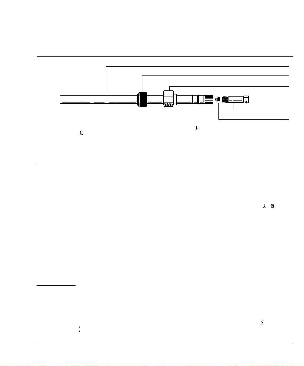
Figure 1-7
Liner
1/4-inch Ferrule
Liner Retainer Nut
Capillary Column Nut
WARNING
Packed Column Inlet Liner for HP Series 530
Capillary Column Use
Nut and Ferrule Installed on a Liner/Adapter
¿
1-mm Graphite Ferrule
With one exception, liners/adapters are installed in the same manner;
if the liner/adapter has not been used before, a new ferrule must be
installed.
¿
The single exception is the adapter to install an HP Series 530
capillary
column in a TCD without provision for capillary makeup gas (Part No.
18740•20950and 18740•20960). In this case, no ferrule is required to
form a seal with the detector base.
Note: A graphite ferrule is strongly recommended; since metal ferrules
tend to lock permanently onto the liner/adapter, their use may require
replacing the entire liner/adapter, should a permanent leak develop.
Exercise care! The oven, and/or inlet or detector fittings may be hot
enough to cause burns.
24
Note: The liner/adapter must be kept as clean as possible to prevent
introducing contamination into the inlet or detector. Use a clean,
lint•freecloth to remove fingerprints, etc., from the end of the
liner/adapter to be inserted into the inlet or detector base. CH
2
OH
(methanol) may be used as a solvent.
Page 25

Columns and Fittings
Inlet inserts
1. Assemble a brass nut and graphite ferrule onto the liner/adapter.
2. Insert the liner/adapter straight into the detector base as far as
3. Holding the liner/adapter in this position, tighten the nut finger•tight.
4. Use a wrench to tighten the nut an additional 1/4 turn.
5. Install the column; then heat the oven, inlet, and detector to desired
Inlet inserts
Inserts are used in inlets, and can be installed from the top of the
particular inlet.
Packed column inlet inserts
possible.
operating temperatures and, only if necessary to stop leaks, tighten
fittings further.
Figure 1-8
Flared End
Glass Insert for Packed Column Inlet Liner
Assuming the correct inlet liner is installed, a glass insert is installed as
described on the next page.
25
Page 26
Columns and Fittings
Inlet inserts
WARNING
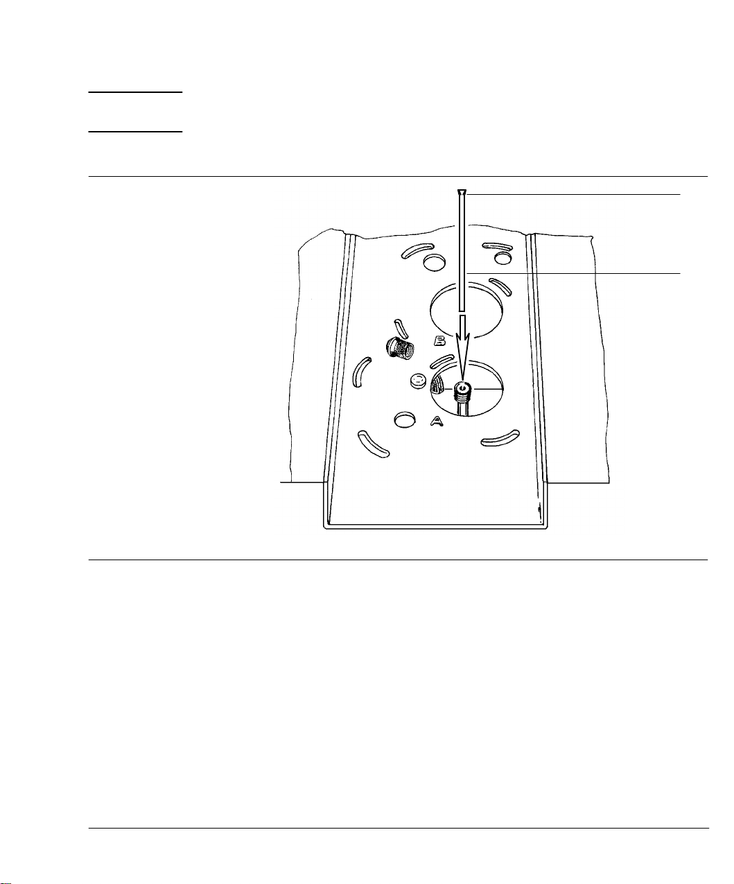
Figure 1-9
Exercise care! the oven, and/or inlet, or detector fittings may be hot
enough to cause burns.
Flared End
Insert
26
Installing a Glass Insert in a Packed Column Inlet
1. In handling the insert, avoid contaminating its surface (particularly
its interior).
2. Remove the septum retainer nut and septum.
3. Carefully remove the old insert (if present) by withdrawing it straight
up. A match stick or similar fibrous item may be used as an aid in
lifting the insert from the inlet.
4. Install the new insert by dropping it carefully, straight into the inlet
liner, flared end up.
Page 27
Columns and Fittings
Inlet inserts
Note: For the liner and insert for an HP Series 530¿capillary column, if
the column is already installed, a new insert may not seat properly in the
liner; the column may prevent it from dropping completely into the liner.
If the insert does not drop completely into the liner, do not force it
(either the liner or the column may shatter); instead, remove the column,
seat the insert, and then replace the column.
5. Replace the septum and septum retainer nut.
Split/splitless or split-only capillary inlet inserts
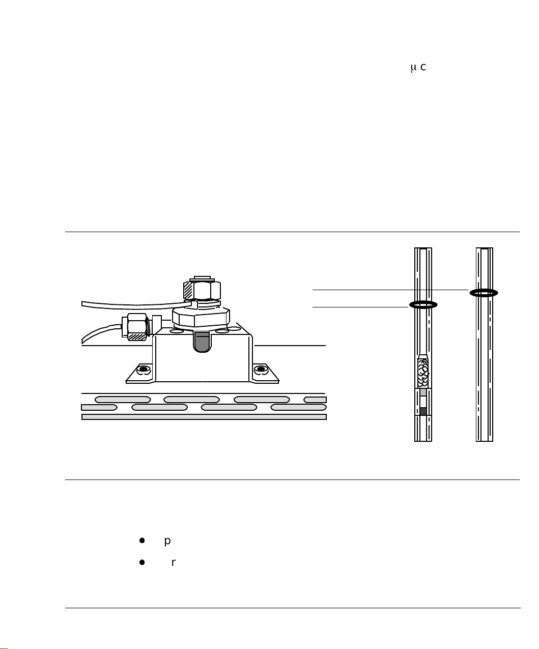
Figure 1-10
Viton O-ring (Preferred)
Viton O-ring
Split Use Splitless Use
Split/Splitless and Split-Only Capillary Inlet and Inserts
A specific inlet insert is required, depending upon the particular
sampling mode. Specific sampling modes include:
C
Split, for major•componentanalyses
C
Purged splitless, for trace•componentanalyses
27
Page 28

Columns and Fittings
Inlet inserts
The split insert contains packing material (10% OV•1on 80/100 High
Performance Chromosorb•W),held in place by silanized glass wool plugs,
located immediately above a mixing chamber. This ensures proper
volatilization and homogeneous mixing of the sample prior to its entry
into the column.
WARNING
Caution
Exercise care! The oven, and/or inlet, or detector fittings may be hot
enough to cause burns.
If operating in split mode, carrier gas pressure must be reduced before
opening the inlet. If not done, pressure may blow insert packing out of
the inlet, altering its characteristics. Pressure is reduced at the
backpressure regulator for the inlet.
1. In handling the insert, avoid contaminating its surface (particularly
its interior).
2. Remove the insert retainer nut. The septum retainer nut need not be
removed from the insert retainer nut assembly.
28
Page 29
Columns and Fittings
Inlet inserts
Figure 1-11
Caution
Installation, Split/Splitless Capillary Inlet Insert
3. Using tweezers, forceps, or similar tool, remove any insert already in
place.
4. Inspect the new insert to be installed: For a split mode insert, the end
with the mixing chamber and packing is inserted first into the inlet.
5. Place a graphite or silicone O•ringon the insert, about 2 to 3 mm from
its top end.
6. Install the insert, pressing it straight down, as far as possible, into
the inlet.
Do not add any seal either at the bottom of the inlet or at the bottom of
the insert; to do so will damage the inlet and/or shatter the insert.
7. Replace the insert retainer nut, tightening it to firm finger•tightness
to form a leak•freeseal. Do not overtighten.
29
Page 30

Columns and Fittings
Jet replacement, FIDs or NPDs
Jet replacement, FIDs or NPDs
Depending upon the column type (packed versus capillary) to be used,
and/or analyses to be performed, exchanging the jet in an FID or NPD
may be necessary. This must be done prior to column installation, and is
particularly important in optimizing FID performance.
Exchanging the jet in either an FID or an NPD is described in Chapter 8,
Preventive Maintenance.
Metal capillary columns
Most metal capillary columns (0.6 to 1.0 mm od) can be connected
directly. Some metal capillaries have a large•diametersleeve soldered on
each end; this must be removed. Use a small triangular file to score the
tubing behind the sleeve; then bend the sleeve back and forth until it
breaks.
30
It is important to have fresh ends of the column, free of burrs, jagged
edges, and/or loose particles of column, stationary phase, and/or material
from a sealing ferrule or O•ring.
Therefore, whenever the column must be cut to provide fresh ends, use
a suitable file to first score the column at the point at which it is to be
broken. This is done normally after installing on the column the column
nut and ferrule (or O•ring)required for installation.
Page 31

2
Keyboard and Displays
Page 32
Keyboard and Displays
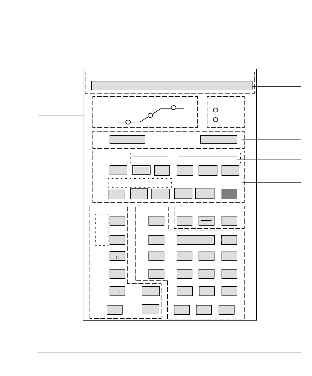
Figure 2-1
HP 5890 SYSTEM READY
OVEN
RATE
Oven Status
INITIAL
TIME
ACTUAL SETPOINT
STATUS
FINAL
TIME
RUN
NOT
READY
Alphanumeric
Display
Instrument
Status
Programmable
Cool on Column
Control
Setpoint
Storage
Control
Signal Definition
and Control
STORE
LOAD
TCD
SENS
STOP START
ON
OFF
A
B
IINIT
TIME
OVEN
TRACK
DET A
TEMP
TIME
RATE
AUX
TEMP
DET B
TEMP
FLOW CRYO
PARAM PARAM
FLOW TIME
ENTER
7 8 9
4
1 2 3
0
TABLE ADD DELETE PREVIOUS NEXT
OVEN
TEMP
PRES PRES
INJ A
TEMP
SIG 1
SIG 2
RANG
E2!()
ZERO
ATTN
2!()
DET
INIT
VALUE
INJ BINJ A
INJ B
TEMP
COL
COMP1
COL
COMP2
FINAL
VALUE
OVEN
MAX
EQUIB
TIME
PURGE
VALVE
.
FINAL
TIME
CLEAR
65
-
Run Control
Timetable
Control
Temperature
Control
Miscellaneous
Functions
Numeric and
Modifier Keys
32
HP 5890 SERIES II Keyboard and Display Panel
Page 33

Keyboard and Displays
Displaying setpoints
HP 5890 SERIES II (hereafter referred to as HP 5890) operation is
monitored and controlled through its front panel keyboard, and
alphanumeric and LED displays.
Some instrument functions are monitored continuously: signal levels,
temperatures, carrier gas flow rates (if electronic flow sensing is
installed), and inlet purge valve status (if a split/splitlesscapillaryinlet
is installed).
There are two general display areas:
C
Alphanumeric Display. Echoes keys pressed at the HP 5890
keyboard show current setpoint values for instrument functions;
actual values of continuously monitored instrument functions; and
warning, error, information, and diagnostic messages.
C
LED Display. Consists of two parts: the left half (OVEN) displays
oven status during a run; the right half (STATUS) gives overall
instrument status at any given time.
Figure 2-2
Displaying setpoints
Any particular instrument current value and/or setpoint is displayed at
the alphanumeric display simply by pressing the appropriate instrument
function key followed possibly by additional modifier" keys necessary to
further define the function (i.e.,
TIME
). For example, pressing
A
OVEN MAX
OVEN MAXIMUM 400
Example, a Typical Alphanumeric Setpoint Display
The name of the function key pressed is always displayed, along with the
current setpoint and/or measured values.
B
or
SIG 1
,
or
might give the display:
ACTUAL SETPOINT
SIG 2,ON
or
OFF
,
33
Page 34

Keyboard and Displays
Entering setpoints
Examples of possible displays are provided where appropriate throughout
the manual.
If a particular function is not installed in your instrument, an
appropriate message is displayed when the key corresponding to the
function is pressed. For example, if no heated zone controlled by
DET B TEMP
Figure 2-3
Typical Display, a Function NOT Installed in the Instrument
Entering setpoints
is installed, pressing
DET B TEMP
ACTUAL SETPOINT
DET B NOT INSTALLED
gives the display:
34
To enter a setpoint value for a particular instrument function, the
function is first displayed by pressing the appropriate key(s).
Once the chosen HP 5890 function is displayed, a new setpoint value can
be entered at any time by pressing appropriate keys
.
-
,
, or possibly
A
,
B,ON
,or
OFF
. For a numeric value,
0
through
9
ENTER
,
is pressed to terminate the entry. Figure 2•4summarizes the two steps
involved.
Page 35

Keyboard and Displays
Entering setpoints
To display the function and its setpoint:
Figure 2-4
(Instrument Function Key) ( or )
A B
necessary for a few
instrument functions
then, EITHER
0 9
( through , , )
-
.
ENTER
to enter a new setpoint value
OR, for a few functions,
ON
(or)
OFF
to switch the function on or off
Steps in Entering a Setpoint Value
For example, to set the A detector zone to 250^C, the following sequence
of keys is pressed:
DET A TEMP
2
5
0
ENTER
function key numeric key(s)
Once detector A temperature is displayed by pressing
DET A TEMP
, the
new setpoint value may be entered at any time thereafter.
Note that the display shows a flashing * (asterisk) while the new
setpoint is entered, disappearing when
When
ENTER
is pressed, the setpoint value is verified and, if satisfactory,
ENTER
is pressed.
becomes the new setpoint for the function. If the entered value is not
satisfactory (out of range, or inconsistent with other, related setpoints),
an appropriate message is displayed. A different value may be entered
immediately, without again pressing the particular function key.
35
Page 36

Keyboard and Displays
Entering setpoints
CLEAR
can be used anytime during an entry, prior to pressing
ENTER
,to
erase the entry in progress. The * disappears, and the original setpoint
display is restored.
Rules regarding keyboard usage are summarized below:
C
An instrument function key, when pressed, is shown in the display
along with its current setpoint value, and actual value for
continuously monitored functions: signal levels, temperatures, flow
rates.
- A displayed function is also ready for entering a new setpoint
value simply by pressing appropriate keys.
C
An * (asterisk) is flashed as the new value is entered, indicating an
entry in progress.
ENTER
C
must terminate a numeric entry. It is also required in
terminating a sequence to assign a particular detector to a given
output signal channel.
In general, any display showing the flashing * must be terminated
ENTER
using
.
36
ENTER
Upon pressing
, the value is verified to ensure it is within the
range permitted for the particular function, and/or that the value is
internally consistent with previously defined setpoint values for other,
related functions.
- If the value is accepted, * disappears from the display indicating
the new value is stored and implemented. For functions whose
values are continuously monitored, * is replaced by the actual
value.
- If the value is out of range, or inconsistent with another setpoint
value, an appropriate message is displayed. Another setpoint
value may be entered immediately without again pressing the
particular instrument function key.
The original setpoint value remains in force until an acceptable entry
is made.
Page 37

Keyboard and Displays
Keyboard operation, INET control
CLEAR
C
is used anytime during setpoint entry, prior to pressing
ENTER
,
to erase the entry in progress.
CLEAR
C
, if pressed when no setpoint entry is in progress, displays
HP 5890 readiness .
C
Run Control Key
START
, if pressed while a setpoint entry is in
progress, causes the entry to be aborted.
C
If a particular key is not valid, it is simply ignored if pressed during
setpoint entry.
C
While an entry is in progress, other instrument function keys are
ignored if pressed, until the current entry is terminated and stored
(
ENTER
) or erased (
CLEAR
).
Keyboard operation, INET control
In general terms, HP 5890 operation is the same whether the instrument
is under local control or INET control (controlled by a separate device). If
the HP 5890 is to be controlled through INET, the following should be
noted:
C
In the event communication is lost (e.g., by power lost at one or more
devices on the loop, a disconnected INET cable, etc.), HP 5890
STOP
and
C
Should the HP 5890 keyboard exhibit problems (keys inactive) while
keys will be disabled.
under INET control, disconnect INET cables at their HP 5890
receptacles; then switch power to the HP 5890 off, and then on. The
keyboard should behave normally (assuming the HP 5890 itself has
no problems).
C
To restore INET control, check that all devices on the loop are
powered on, and that all INET cables are installed properly. The
system should return to normal operation automatically.
START
37
Page 38

Keyboard and Displays
Protecting setpoints
Additional information regarding INET control is available in Chapter 5,
Signal Output. Servicing may be required for one or more devices on the
INET loop if communication cannot be established.
Protecting setpoints
The HP 5890 provides a keyboard lock feature to minimize possibility of
stored setpoints being altered unintentionally. When the HP 5890
keyboard is locked, setpoint values (numeric values, A, B, OFF, and
ON) may only be displayed; they cannot be altered.
remain functional, so runs may be started or stopped.
To lock instrument setpoints, first enter the key sequence:
START
and
STOP
Figure 2-5
CLEAR
Then press
.
ON
ENTER
-
to lock the keyboard, or
OFF
to unlock the keyboard.
Figure 2•5shows displays occurring during this process.
ACTUAL SETPOINT
CALIB AND TEST [0-0]
ACTUAL SETPOINT
KEYBOARD LOCK ON
ACTUAL SETPOINT
KEYBOARD LOCK OFF
Keyboard Lock Displays
38
Page 39

Keyboard and Displays
Loading default setpoints
With the keyboard locked, Figure 2•6shows the display occurring if a
setpoint entry is attempted:
Figure 2-6
KEYBOARD LOCKED Message Display
If the HP 5890 keyboard is locked while the instrument is under INET
control, a setpoint file may be loaded into HP 5890 memory from the
controller, but the loaded setpoints cannot then be edited at the HP 5890
keyboard until it is unlocked.
After locking or unlocking the keyboard, return to operation by pressing
any function key (e.g.,
KEYBOARD LOCKED
OVEN TEMP
).
ACTUAL SETPOINT
Loading default setpoints
This function permits resetting HP 5890 operating setpoints to a
standard set of values. Only the following information is retained:
C
Calibration constants for oven temperature control
C
All gas flow rate monitoring information (gas types and calibration
constants)
C
Column compensation data, including detector assignments
Note: Since user•definedsetpoints are lost in the process, any critical
HP 5890 setpoints should be recorded for later reentry before proceeding.
Through the keyboard, select CALIB AND TEST mode, function 6:
CLEAR
.
6
39
Page 40

Keyboard and Displays
Loading default setpoints
Upon pressing
ENTER
, default setpoints are loaded into memory, erasing
setpoints already present. Table 2•1lists resulting HP 5890 default
setpoints.
Table 2-1. HP 5890 Default Setpoints
Function Default Setpoint
^
Inj Temp (A & B): 50
Det Temp (A & B): 50
Oven Temp: 50
Oven Max Temp: 400
Cryo Cooling: OFF
Cryo Blast OFF
Equib Time: 3 min
Init Temp: 50
Init Time: 650 min
Oven Prog Rates: 0
Final Temp: 0
Final Time: 0 min
Inlet Purge: ON
Purge Time: 0 min
Detector (A & B): OFF
Signal 1 Det: Detector A
Signal 2 Det: Detector B if BOTH detectors A and
Range (1 & 2): 0
Attn (1 & 2): 0, ON
Zero (1 & 2): 0, ON
HP-IL (INET): Address- 31
INET: Global (unconfigured)
Keyboard Lock: OFF
Timetable Empty
Inj A Pres OFF
Inj B Pres OFF
TCD Sens HIGH
Oven Track ON
Constant Flow OFF
C, OFF
^
C, OFF
^
C, OFF
^
C
^
C
^
C/min
^
C
B are installed; otherwise,detector A.
40
Page 41

Keyboard and Displays
Loading default setpoints
Note that if the battery protecting memory should fail when main power
is turned off, the default setpoints are loaded into memory when the
battery is replaced. In addition, calibration constants for oven
temperature control and gas flow rate monitoring are also reset to default
values.
41
Page 42

This page intentionally left blank.
Page 43

3
Temperature Control
Page 44

Temperature Control
Oven temperature, and temperatures of up to five separate heated zones
(detectors, inlets, and/or heated valves), are controlled through keys
shown in Figure 3•1.
Figure 3-1
Oven Control
Figure 3-2
OVEN
TEMP
INJ A
TEMP
INIT
VALUE
INJ B
TEMP
INIT
TIME
DET A
TEMP
RATE
AUX
TEMP
DET B
TEMP
FINAL
VALUE
OVEN
MAX
EQUIB
TIME
FINAL
TIME
Heated Zone Control
Temperature Control Keys
In these cases, both current setpoint value and current monitored value
are displayed by pressing the appropriate temperature control key. For
example, Figure 3•2shows typical displays obtained by pressing
OVEN TEMP
.
ACTUAL SETPOINT
OVEN TEMP 279 350
44
Typical Display, Setpoint and Current Value
Page 45

Temperature Control
Note that the ACTUAL value is a measured quantity, while the
SETPOINT value is user•defined:in this example, the setpoint value for
oven temperature might recently have been changed from 250 to 350
and the oven is now heating to the new setpoint. Given sufficient time for
equilibration, ACTUAL and SETPOINT values become equal.
In addition to keys
defining setpoint values,
specific key sequences:
0
through
ON,OFF,A
^
C,
.
-
9
,
,
, and
CLEAR
,
B
, and
are used in certain
ENTER
used in
ON
C
and
OFF
add convenience in being able to switch on or off the
oven, and/or heated zones, without losing their current setpoint
values.
A
C
and
temperature program:
parameters for the second ramp;
B
are used in key sequences defining a multiple•rampoven
A
as part of key sequences defining
B
as part of key sequences
defining parameters for the third ramp.
45
Page 46

Temperature Control
e
Valid setpoint ranges
Valid setpoint ranges
Table 3•1lists valid setpoint ranges for the 13 keys controlling oven and
heated zone temperatures.
Table 3-1. Valid Setpoint Ranges For Temperature Control Keys
Key
OVEN TEMP
INIT TEMP
INIT TIME
RATE
FINAL TEMP
FINAL TIME
OVEN MAX
EQUIB TIME
INJ A TEMP
INJ B TEMP
DET A TEMP
DET B TEMP
AUX TEMP
Valid
Setpoint Range
In
Increments Of Function
-80 to 450 1^C Oven Control
-80 to 450 1
^
C Oven Control
0 to 650.00 0.01 minute Oven Control
0 to 70 0.1 /minute Oven Control
-80 to 450 1
^
C Oven Control
0 to 650.00 0.01 minute Oven Control
70 to 450 1
^
C Oven Control
0 to 200.00 0.01 minute Oven Control
0 to 400 1
0 to 400 1
^
C Zone Control
^
C Zone Control
0 to 400* 1^C Zone Control
0 to 400* 1
^
C Zone Control
0 to 400 1^C Zone Control
NOTE: TOTAL run time will not exceed 650.00 minutes regardless of values enter
INIT TIME
RATE FINALTIME
, , and .
*The valid setpoint range for a Flame Ionization Detector is 0 to 450^C.
46
Page 47

Temperature Control
Cryogenic (sub-ambient) oven control
Cryogenic (sub-ambient) oven control
Liquid N1or liquid CO1cryogenic options are for operation at
temperatures less than about 7
operation of a valve which opens when coolant is demanded and closes
when the setpoint temperature is reached.
^
C above ambient. This is done through
Figure 3-3
When you press
gold CRYO PARAM CRYO PARAM CRYO PARAM
you scroll
through a series of displays for choosing cryogenic options. These options
include CRYO for operation during the entire run, CRYO BLAST, for very
fast cool down between runs, and AMBIENT to regulate on and off times
to optimize coolant use.
ACTUAL SETPOINT
CRYO ON
ACTUAL SETPOINT
CRYO BLAST ON
ACTUAL SETPOINT
AMBIENT 25
Cryogenic options
For operation duringruns at
subambient temperatures.
For very fast cool down
between runs.
Lets you regulate Cryo and
Cryo Blast on and off times to
optimize coolant use. Default is
25
^
C and need not be changed
unless
ambient differs by 10
^
.
The following figures show the oven temperature profile for a typical run,
showing the on and off times for CRYO and CRYO BLAST.
47
Page 48

Temperature Control
Cryogenic (sub-ambient) oven control
Figure 3-4
75
50
25
Figure 3- 5.
120
80
40
CRYO OFF at ambient +15
^
9
(CRYO ON)
Oven profile using CRYO, for operation
during runs at subambient temperatures
9
CRYO BLAST ON
ambient + 50
9
CRYO ON
at ambient + 25
^
CRYO BLAST OFF
9
(30 sec. modulation)
^
48
Oven profile using CRYO BLAST, for very fast cool down between runs
Page 49

Temperature Control
Programming oven temperature
Programming oven temperature
HP 5890 oven temperature programming allows up to three ramps, in
any combination of heating or cooling. Keys defining an oven temperature
program include:
INIT TEMP
INIT TIME
RATE
FINAL TEMP
FINAL TIME
A setpoint temperature value at which the oven is
maintained at the beginning of a temperature•programmed
run. This is also the temperature to which the oven returns
at termination of the temperature•programmedrun.
When not in a run, the setpoint value for
equals
OVEN TEMP
.
Time for which oven temperature is held at
INIT TEMP
INIT TEMP
.
Rate at which the oven is to be heated or cooled.
Temperature the oven attains at the end of a heating or
cooling ramp.
In a multiple•ramptemperature program, final
temperature for one ramp is also the initial temperature
for the next ramp.
Time period over which oven temperature is held at
FINAL TEMP
.
In a multiple•ramptemperature program, final time for one
ramp is also the initial time for the next ramp.
total elapsed time for a run cannot exceed 650 minutes: at 650 minutes,
the run terminates and oven temperature recycles to
calculated total length of time anticipated for a run,
INIT TEMP
TIME
. To know
is pressed
repeatedly until a NEXT RUN display is obtained.
49
Page 50

Temperature Control
Oven status
In isothermal operation (
RATE
= 0 ), if
INIT TIME
is set equal to 0
(zero), the HP 5890 internally sets run time to the maximum, 650
minutes.
A
is included in key sequences defining parameters for a second ramp;
B
is included in key sequences defining parameters for a third ramp.
In isothermal operation, and in one•or two•ramptemperature programs,
rate for the next ramp must be set to 0 (zero) to prevent further
programming.
In oven temperature programming, once any one of the five temperature
programming functions (
FINAL TIME
) is displayed, pressing
INIT TEMP
INIT TIME
,
ENTER
, without entering a new
RATE
,
FINAL TEMP
,
, and
setpoint value, rolls the display successively through the entire group,
(including A and B displays for second and third ramps).
This is an efficient way in which to review and, if necessary, change oven
temperature program setpoints.
Oven status
50
During a temperature•programmedrun, the LED OVEN display provides
indication of oven status at any given time:
C
Isothermal Run: Assuming
than 0, and that
RATE
=0,only the INITIAL TIME LED is lit. It
INIT TIME
is assigned a value greater
remains lit throughout the run.
C
Single•Ramp Temperature Program: The three LEDs, INITIAL
TIME, RATE, and FINAL TIME, successively light to indicate position
in the temperature program.
C
Multiple•Ramp Temperature Program: The three LEDs, INITIAL
TIME, RATE, and FINAL TIME, successively light to indicate position
in the first temperature program ramp.
Then RATE and FINAL TIME LEDs light alternately as the program
proceeds through the second (and third) ramp(s).
Page 51

Temperature Control
Oven safety
In complex two•or three•rampoven temperature programs, information
as to the part of the program in progress is monitored by pressing
OVEN TEMP
Note that, during a ramp, the SETPOINT value displayed is that
calculated to be the correct temperature, based upon specified
heating/cooling rate, and initial and final oven temperatures.
Also, note that if the RATE LED is observed to blink during oven heating,
this indicates the particular
given operating conditions: the oven heater is operating at full power and
may not be able to deliver the desired temperature program rate. Such a
situation compromises accuracy in repeating the heating ramp from run
to run.
Oven safety
.
RATE
value entered is too aggressive for the
WARNING
Normally, the oven should be switched off (
OVEN TEMP
OFF
) prior to
accessing the oven interior (e.g., to change columns, check for leaks, etc.).
For safety, this turns off power to the oven heater, fan, and cryogenic
valve (if installed), but maintains the setpoint value in memory.
The oven is equipped with a shut•offfeature to protect against
unintentional opening of the oven door, and/or the possibility of
mechanical and/or electronic failure affecting oven operation.
At any time during normal above•ambientoperation, if the oven cannot
attain and/or maintain an entered setpoint temperature, a problem is
assumed and the oven is automatically switched off. Examples of possible
problems include the oven door open (or closed but not properly latched),
inoperative oven vent flaps, failure of the oven fan, heater, or
temperature sensor, or electronic problem.
If the oven door is opened, a time delay may be observed before the
oven shuts itself off. The closer the oven is to ambient temperature,
the longer the delay will be.
51
Page 52

Temperature Control
Fault: messages
The message displayed when this occurs is shown in Figure 3•6.
Figure 3-6
Message, Oven SHUT DOWN
The oven remains off until switched on again via the keyboard
OVEN TEMP
(
Fault: messages). Power to the instrument must be switched off, and then
on again to restore operation (setpoints are maintained).
Fault: messages
Figure 3•7shows possible FAULT: messages associated with heated zones
or the oven. In general, the following problems are indicated when a
FAULT: message appears:
ACTUAL SETPOINT
WARN: OVEN SHUT OFF
ON
), unless a FAULT: message is displayed (see below,
52
C
ADC OFFSET indicates a problem with one or more electronic
components in circuitry associated with temperature control.
C
LINE SENSE indicates a problem with AC power to the instrument
(an excessively high source voltage).
C
Any of the TEMP RDG messages indicate an inoperative temperature
sensor for the indicated zone or oven.
C
OVEN > MAX + 20 indicates oven temperature exceeds the current
OVEN MAX
setpoint value by more than 20^C. Thermal run•awayis
the likely cause.
Note: In case multiple problems exist simultaneously, press
CLEAR
roll through all message displays.
to
Page 53

Temperature Control
After a power failure . . .
Figure 3-7
Thermal Control FAULT: Messages
ACTUAL SETPOINT
FAULT: ADC OFFSET
ACTUAL SETPOINT
FAULT: LINE SENSE
ACTUAL SETPOINT
FAULT: INJA TEMP RDG
ACTUAL SETPOINT
FAULT: DETA TEMP RDG
ACTUAL SETPOINT
FAULT: OVEN TEMP RDG
ACTUAL SETPOINT
FAULT: OVEN > MAX+20
In addition to the message, the red NOT READY LED blinks. All zones
and the oven are turned off and made inoperative until power is switched
off, and then on again (setpoints are maintained).
After a power failure . . .
Setpoint values are protected during a power failure (even if intentional,
by disconnecting the power cord, or by switching off the HP 5890 at its
main power switch) by a lithium battery (10•yearnominal life) which
maintains power to HP 5890 memory.
After power is restored, a message is displayed, as shown in Figure 3•8.
53
Page 54

Temperature Control
Oven temperature calibration
Figure 3-8
ACTUAL SETPOINT
PASSED SELF TEST
INITIAL
TIME
RATE
OVEN
FINAL
TIME
STATUS
RUN
NOT
READY
Message Display, Power Failure and Recovery
Heated zones return to their respective setpoint values, after which the
oven returns to its setpoint value.
If
OVEN TEMP
is displayed after recovery from a power failure, and if
C
the oven was ON before the power failure, the oven display shows the
actual oven temperature value, and cycles between showing the
setpoint value and OFF until other zones achieve their respective
setpoint temperatures.
C
The oven can be switched ON through the keyboard at any time,
without waiting for heated zones to first come to correct temperature.
C
An analytical or column compensation run in progress at the time of a
power failure is aborted; similarly, a keyboard entry in progress is
aborted.
54
Oven temperature calibration
To maximize precision with respect to retention time information,
particularly if retention times are to be compared between
chromatographs, it may be necessary to calibrate oven temperature in the
range of interest using an independent temperature•measuringdevice.
With the factory•setcalibration difference value of 0 (zero), displayed
oven temperature is accurate to within 1% of the actual temperature,
expressed in
^
K (Kelvin).
Page 55

Temperature Control
Oven temperature calibration
The HP 5890 providesthe means to (if necessary) reset oven temperature
monitoring so the displayed ACTUAL value accurately represents the
correct temperature.
Oven temperature calibration requires entering the difference (delta)
^
value (in
C) between an independently measured temperature value
versus the corresponding displayed oven temperature value:
Correction Value =
Measured Temperature (
For example, if actual measured oven temperature were found to be
148.73
^
C, while the corresponding displayed value was 150.00, the
calibration difference value to be entered would be -1.27.
Setting the oven calibration value
An oven temperature calibration measurement should be made at a
temperature in the middle of the range of interest. Allow ample time (up
to 1/2•hour)for thermal equilibration at the selected temperature; no
drift should be observed. The temperature•sensingprobe should be placed
in the region of the oven occupied by the column(s).
^
C) - Displayed Temperature (^C)
1. Through the keyboard, select CALIB AND TEST mode, function 1:
CLEAR
.
ENTER
1
CALIB is displayed, followed by two values: the observed oven
temperature (to 0.01
^
C), and the current difference (delta)
calibration value.
Note: Record the displayed calibration delta value! If problems are
encountered in recalibration, the value may be reentered.
2. Assuming no drift in temperature, the new difference (delta) value is
then entered by pressing appropriate number keys, followed by
appropriatevalue
ENTER
ENTER
:
55
Page 56

Temperature Control
Oven temperature calibration
3. CALIB DELTA is displayed until
ENTER
is pressed; then oven
temperature recalibration occurs. Note that, after calibration, the
displayed oven temperature value should match closely the measured
value.
Any delta value within the range -10.00 through +10.00
^
C may be
entered. If a value outside this range is entered, the message
CORRECTION TOO HIGH is displayed.
Assuming the battery protecting HP 5890 memory is operational, a new
calibration constant remains in effect even if the instrument is switched
off, or disconnected from its power source, or if power fails.
56
Page 57

4
Electronic Flow Sensing
Page 58

Electronic Flow Sensing
Two channels of electronic flow rate sensing continuously monitor gas
flow rates (usually carrier) in the HP 5890 SERIES II. Proper scaling of
displayed values for different commonly used gases is defined through
keyboard entries. The two flow channels are distinguished through
and
If carrier gas flows are monitored, A implies flow through column A
(nearest the instrument front); B implies flow through column B (nearest
the instrument rear).
Displayed flow rate values are in ml/minute.
Displaying gas flow rate
Current flow rate is displayed by pressing:
B
.
A
Figure 4-1
58
FLOW A
(or
B
)
Typical gas flow rate displays are shown in Figure 4•1:
ACTUAL SETPOINT
FLOW A 25.4 N2
ACTUAL SETPOINT
NO FLOW SENSOR
Typical Electronic Flow Rate Sensor Displays
Page 59

Electronic Flow Sensing
Designating gas type
Designating gas type
To scale the displayed flow rate value properly, one of four commonly used
gases must be designated. The appropriate gas type is selected according
to Table 4•1:
Table 4-1. Defining Type of Gas to be Monitored
Number Gas Type Preferred Use
1 He (Helium) TCD
2N
3H
4 Ar/CH
(Nitrogen) General
2
(Hydrogen) Capillary
2
(Methane in Argon) ECD
4
To select one of these gases for a particular flow channel, press:
FLOW
1
2
,
ENTER
, the current flow rate is displayed, scaled appropriately for the
B
(
) to display FLOW A (or FLOW B).
3
,
,or
4
is then pressed, followed by
ENTER
. Upon pressing
chosen gas type.
If a gas other than one of the above standard four is used, select He,
N
1,H1
, or Ar/CH3according to which one is closestin thermal
conductivity to the gas being used. Under no circumstances should any
corrosive gas be passed through the EFS.
The maximum usable range for H
( >100 ml/min), where a gas other than He, N
1
is 100 ml/minute. At higher flow rates
1
, or Ar/CH3is being used,
or to ensure maximum accuracy in displayed flow rate, calibration of the
EFS may be necessary.
59
Page 60

Electronic Flow Sensing
Electronic flow sensor (EFS) calibration
Electronic flow sensor (EFS) calibration
Electronic flow sensor (EFS) calibration may be performed any time to
ensure displayed flow rate accurately represents real gas flow rate
through the sensor. The EFS is factory•calibratedfor four standard
gases, H
ml/min. This covers the majority of chromatographic applications.
Two situations where it would be appropriate to perform recalibration
would be where a nonstandard gas is to be used (e.g., something other
than H
to be used.
EFS calibration requires setting two values for a given flow
channel•first, the zero value (defined with no flow through the given
flow channel) and then the gain value (calculated, based upon a
measured flow rate value).
1
, He, N1, and Ar/CH3, within the flow rate range of 0 to 100
1
, He, N1, or Ar/CH3), or if flow rates in excess of 100 ml/min are
WARNING
60
If calibration is being performed for H2, observe proper safety
precautions to prevent fire or explosion hazard.
Prior to performing the calibration procedure, the following must be done:
C
The instrument must be on for at least one hour for thermal
equilibration of the EFS.
C
Since gas flow through the channel to be calibrated will be
interrupted, detectors should be turned off (particularly an NPD or
TCD! ), and the oven cooled to ambient temperature (to protect
columns).
C
A flow•measuringdevice is required, accurate to better than 1 ml/min.
C
The EFS is calibrated to measure volumetric flow at standard
temperature and pressure. Flows measured at ambient temperature
with a bubble flow meter will have to be converted from ambient
temperature and pressure to standard temperature and pressure.
Page 61

Electronic Flow Sensing
Electronic flow sensor (EFS) calibration
Preparation
1. Access the EFS by removing the left side panel; remove two screws
along its lower edge, slide the panel toward the rear of the
instrument, and then lift.
2. Through the keyboard, select CALIB AND TEST mode, function 2:
CLEAR
.
ENTER
2
GAIN A is displayed, followed by two values: the observed flow rate
through Channel A, and the current gain calibration value for
Channel A.
Setting the zero calibration value
The zero calibration value must be set with no gas flow through the
channel being calibrated.
ZERO
1. Press
current zero calibration value for EFS Channel A). Note that
Channel A is assumed by default; if channel B is to be calibrated
instead, press
2. Disconnect the gas source to the particular flow channel being
calibrated. Do not trust an on/off valve, pressure regulator, or mass
flow controller to be an effective shutoff device; any gas flowing
through the EFS will invalidate the zero calibration value.
Disconnect the source at any convenient point (e.g., at the connection
of the supply line into the instrument).
: FLOW A ZERO is displayed, followed by a value (the
B
.
61
Page 62

Electronic Flow Sensing
Electronic flow sensor (EFS) calibration
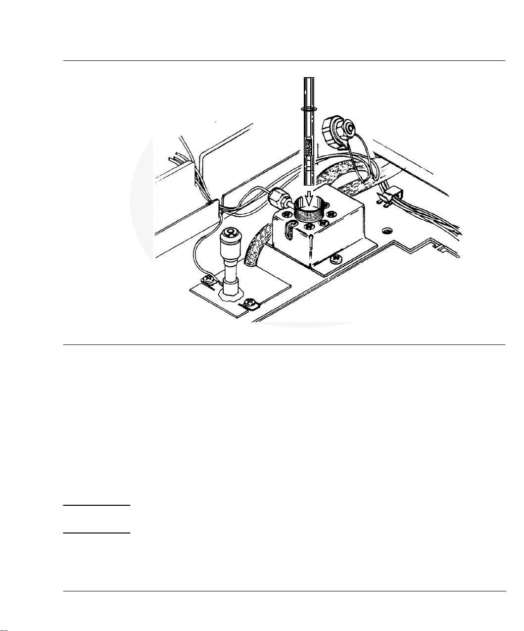
3. Locate the EFS module and note its labelling: CHANNEL A/
CHANNEL B, IN/OUT. For the channel being calibrated, locate and
disconnect its OUT fitting; use two wrenches in opposition to prevent
twisting the tubes.
Figure 4-2
Outlet Line, Channel B
EFS Module
Detail, Electronic Flow Sensor (EFS) Module
Outlet Line, Channel
A
4. Install the EFS flow•measuringadapter (Part No. 05890•80620)into
the female OUT fitting to the EFS module. Connect a bubble flow
meter to the adapter.
62
Allow ample time (up to 1/2•hour)for residual gas within connected
plumbing to bleed off. Verify that absolutely no flow is observed at
the connected bubble flow meter.
Page 63

Electronic Flow Sensing
Electronic flow sensor (EFS) calibration
Figure 4-3
EFS Flow-Measuring Adapter (Part No. 05890-80620)
5. Assuming there is no gas flow through the channel being calibrated,
press
ENTER
at the keyboard. This updates the zero calibration value.
Setting the GAIN calibration value
After the zero calibration value is set at zero flow rate through the given
channel, the gain calibration value must be set, based upon a measured
flow rate.
1. At the keyboard, press
FLOW
: GAIN A (or GAIN B) is displayed,
followed by two values (the observed flow rate through the channel,
and the current gain calibration value for the channel).
2. Reconnect the gas supply to the channel being calibrated. Do not
reconnect the OUT fitting for the particular channel.
3. Using a suitable flow•measuringdevice (accurate to better than
1 ml/min) connected at the OUT fitting for the given channel, adjust
flow through the channel so measured flow rate is approximately in
the middle of the range to be used. For example, if the range of flow
rates to be used is between 50 and 150 ml/min, measured flow rate
should be adjusted to about 100 ml/min.
63
Page 64

Electronic Flow Sensing
Electronic flow sensor (EFS) calibration
Note: The HP 5890 has a timer function that may be used as an aid
in measuring flow rate (see the Operating Manual, Chapter 4).
C
Press
C
After obtaining the desired flow rate, press:
CLEAR
C
EFS channel A is assumed. Press
TIME
.
to access the timer function.
ENTER
2
to return to setting the gain value.
B
if Channel B is being
calibrated.
4. Allow ample time for flow rate to equilibrate (no drift should be
observed).
5. Assuming no drift in measured flow rate, note the flow rate value at
the connected flow•measuringdevice. Enter this measured value
through the keyboard:
Measured Value
Upon pressing
ENTER
ENTER
, CALIBRATING is displayed.
6. After a short time, GAIN A (or GAIN B) is again displayed, followed by
the observed flow rate and a new gain calibration value based upon
the measured flow rate.
Note that the displayed flow rate value now should be quite close to
the measured flow rate value. If not, drift may have occurred, so the
process should be repeated.
64
7. This completes EFS calibration. Remove the flow•measuringadapter,
reconnect channel OUT fittings (use two wrenches in opposition to
avoid twisting tubes), replace the left side panel, and restore the
instrument to service.
Page 65

Electronic Flow Sensing
Electronic flow sensor (EFS) calibration
Entering specific ZERO and GAIN values
Calibration values for zero and gain should be recorded when a
particular channel is calibrated. They can then be reentered through the
keyboard if necessary, without repeating the entire calibration procedure.
To enter specific zero and gain calibration values:
1. Select CALIB AND TEST mode, function 2:
CLEAR
.
ENTER
2
GAIN A (or GAIN B) is displayed, followed by two values (the observed
flow rate through the channel and the current gain calibration value
for the channel).
Note that Channel A is assumed by default. If Channel B is to be
calibrated instead, press
2. Enter the desired gain calibration value, preceded by
-
Numeric Value
-
is necessary to signify entry of a gain calibration value, rather
B
.
-
:
ENTER
than a measured flow rate.
ZERO
3. Press
: FLOW A ZERO is displayed, followed by a value (the
current zero calibration value for EFS Channel A).
Note that Channel A is assumed by default. If Channel B is to be
B
calibrated instead, press
.
4. Enter the desired zero calibration value:
ZERO
ENTER
or
FLOW
displays either the zero
Numeric Value
Note that alternately pressing
calibration value or the gain calibration value for the given channel (A
or B).
65
Page 66

This page intentionally left blank.
Page 67

5
Signal Output
Page 68

Signal Output
A standard signal channel, controlled via
A second signal channel, controlled via
SIG 1
, always is provided.
SIG 2
, is provided if Option 550/
Accessory 19242A (Communications Interface Board ), or Option 560/
Accessory 19254A (RS•232), is installed.
Output sources include detector signal(s), heated zone or oven
temperatures, carrier gas flow rates, column compensation run data, or
test chromatographic data. If both signal channels are present, each may
output information simultaneously from the same source, or from two
different sources.
For either channel, two separate levels of ANALOG output are provided,
depending upon the analog signal cable used: +1 V or 1 mV.
0 to +1 mV: for strip chart recorders.
-0.01 to +1 V: for electronic integrators with analog inputs.
The two output levels are independent, and may be connected
simultaneously to separate data•receivingdevices.
Note: A tick mark (electrical pulse) is produced at the +1 mV analog
output when either
START
or
STOP
is pressed, and when a run
timesout (run time elapses). These marks locate beginning and ending
points in a chromatogram plotted at a continuously running strip chart
recorder.
68
Zeroing signal output
Acting on +1 mV and +1 V analog outputs,
offset which is then subtracted from the output signal (prior to signal
attenuation by
RANGE 2!()
or
ATTN 2!()
ZERO
defines a constant
).
Page 69

Signal Output
Zeroing signal output
Figure 5-1
The function of
ZERO
is to subtract a constant background signal from
the detector signal. Background signal sources include the detector itself
(background level depending upon detector type), column bleed, or
contaminants in supply gas(es).
SIG 1
ZERO
setpoint
SIG 2
or
), followed by
ZERO
(or simply press
Displaying current
Current
signal channel key (
ZERO
ZERO
setpoint value is displayed by pressing the appropriate
alone, if the desired signal channel is already displayed). Typical
displays are shown in Figure 5•1.
ACTUAL SETPOINT
SIG 1 ZERO 104.5
ACTUAL SETPOINT
SIG 2 NOT INSTALLED
ACTUAL SETPOINT
ZERO 1 104.5 OFF
ACTUAL SETPOINT
ZERO LIMIT = 83000
Typical Displays
ZERO
Table 5•1lists conversions between detector units and the scale used for
ZERO
setpoint values.
-12
ZERO
A)
Table 5-1. Conversions from Detector Units to Setpoint Values
Detector
Conversion
ZERO
(1.0 unit = )
FID & NPD 1.0 pA (1.0}10
¿
TCD 25
V (2.5}10-5V)
ECD 10 Hz
69
Page 70

Signal Output
Zeroing signal output
Figure 5-2
O
U
T
P
U
T
V
O
L
T
A
G
E
Self-
Referencing Figure 5•2for the +1 V output, note that using
ZERO
setpoint
ZERO
increase dynamic range available for signal output by shifting an existing
constant offset signal to a lower level (usually electrical zero). There are
limits to this, however, so it is good practice to have background reduced
as much as possible by minimizing column bleed, using clean supply
gases, and by performing proper detector maintenance.
ZERO
1.0 V usable
dynamic range
+ 1.000 V
+ 0.100 V
0V
1 V Output: Canceling BaselineOffset (the self- function)
1.0 V maximumoutput level
0.9 V usable
dynamic range
ENTERZERO
pressed
Constant 0.100 V
detector background
signal
HP 5890 SERIES II electrical zero
can
70
-0.010 V
Effect of on the +1 V Analog Output
ZERO
Page 71

Signal Output
Zeroing signal output
Figure 5-3
O
+ 1.000 mV
U
T
P
U
T
V
O
L
T
+ 0.100 mV
A
G
E
+ 0.006 mV
1 mV Output: CancelingBaseline Offset (the self- function)
1.0 mV maximum output level
0.9 mV usable
dynamic range
ENTERZERO
pressed
Constant 0.1 mV
detector background
signal
HP 5890 SERIES II electrical zero
0mV
Effect of on the +1 mV Analog Output
ZERO
ZERO
1.0 mV usable
dynamic range
The example in Figure 5•2is in terms of the +1 V analog output. In
Figure 5•3,identical treatment is made for the +1 mV output, except that
the signal is shifted to an offset somewhat above electrical zero. This
ensures a small positive offset (about 6% of full scale) in pen position at a
connected chart recorder, and permits uninterrupted plotting, even if a
small negative baseline drift occurs.
Once current
channel, pressing
ZERO
setpoint value is displayed for the desired signal
ENTER
causes the value to be changed to the current
signal value.
Self•
ZERO
should be done only at times of quiet chromatographic
activity (i.e., not during a run). To do so during an active run may cause a
baseline shift at the recording/integrating device.
71
Page 72

Signal Output
Signal attenuation
Note: If a self•
exceeding the maximum permitted setpoint value for
User•defined
ZERO
determination is performed on an active signal
ZERO
ZERO
setpoint), the maximum setpoint value is assigned
(see
and the message SIG 1 (or 2) ZERO TOO HIGH is displayed.
User-defined
If the self•
ZERO
setpoint
ZERO
setpoint value determination is not appropriate for a
particular application, any value from -830000.0 through 830000.0
may be entered at the keyboard.
Entering a value less than the self•
ZERO
value shifts background
baseline upward (but at the expense of available output range); for
example, to capture negative peaks, or to compensate for negative
baseline drift.
Signal attenuation
Analog signal output levels (+1mV or +1 V outputs) for either signal
channel (controlled by
SIG 1
, and by
19242A or Option 560/Accessory 19254A is installed) are attenuated via
RANGE 2!()
and
ATTN 2!()
.
SIG 2
if Option 550/Accessory
72
RANGE 2!()
For
signal level by a factor of 2 (half the previous level). Also,
, each step to a higher setpoint value decreases the output
RANGE 2!()
affects signal level at both the +1 V and +1 mV analog outputs.
Signal
+1 V Output Level =
ATTN 2!()
affects only the +1 mV analog output: each step to a higher
value reduces the output signal level (as defined by
+1 mV Output Level =
RANGE 2!()
2
RANGE 2!()
2
Signal
}
RANGE 2!()
ATTN 2!()
2
) by half.
Page 73

Signal Output
Signal attenuation
Thus, signal output level at the +1 mV analog output may be set
separately from that at the +1 V output.
Table 5•2gives values permitted for either function, and the output
affected.
Table 5-2. Valid Setpoints for and
RANGE 2!() ATTN 2!()
Permitted
SetpointsKey
RANGE 2!()
ATTN 2!()
Note:
ATTN 2!()
0 to 13 Both +1 mV & +1 V
0 TO 10 Only +1 mV
OFF
ON
,
functions only for the +1mV output, and acts on the
signal after it has been ranged by
RANGE 2!()
Affected Output
.
Generally, if both an integrator or A/D converter (+1 V output) and chart
recorder (+1mV output) are connected to the same signal channel,
RANGE 2!()
then
should be set properly first for the integrator or computer,
ATTN 2!()
set appropriately for the chart recorder.
To minimize integration error for an integrator or A/D converter,
RANGE 2!()
normally should be set to the lowest value possible, provided
the largest peaks of interest do not exceed 1 volt. Attenuation functions
at the integrating device or computer are then used to ensure that plotted
peaks remain on scale.
RANGE 2!()
selects and sizes a portion of the full dynamic range for the
signal source assigned to an output channel. The portion selected is sized
such that the highest possible value for the portion does not exceed
maximum output voltage allowed for the given output (+1 mV or +1 V).
ATTN 2!()
further selects and sizes a portion of the ranged signal for
the +1 mV output to ensure that the signal does not exceed +1 mV.
73
Page 74

Signal Output
Signal attenuation
For analytical information from a detector, proper settings for
ATTN 2!()
and
are determined such that peaks of interest are on scale
at the integrator or chart recorder: peaks of interest must neither flat
top by exceeding the allowed maximum output level, nor be too small to
be measured. Table 5•3lists maximum detector output producing +1 volt
at the +1V output for each
Table 5-3. Detector Output Producing a 1 V Signal
Maximum Detector Signal
Producing +1 V Output
RANGE 2!()
0 1.0}10
1 2.0
2 4.0}10
3 8.0
4 1.6}10
5 3.2
FID & NPD (pA)
3
3
}
10
3
3
}
10
4
4
}
10
(mV, High Gain)
RANGE 2!()
TCD
25 800 10
50
CC
CC
CC
CC
setpoint value.
TCD
(mV, Low Gain)
C
RANGE 2!()
ECD (kHz)
20
40
80
160
320
6 6.4}10
7 1.3}10
8 2.6}10
9 5.1}10
10 1.0}10
11 2.0}10
12 4.1}10
13 8.2}10
74
4
5
5
5
6
6
6
6
CCC
CCC
CCC
CCC
CCC
CCC
CCC
CCC
Page 75

Signal Output
Signal attenuation
Figure 5-4
From Table 5•3,note that for a TCD,
RANGE 2!()
= 0 is suitable for
virtually all applications since the entire linear output range of the
detector is included. Likewise,
RANGE 2!()
settings from 0 through 5cover
the entire useful output range for an ECD. Only an FID or NPD may
RANGE 2!()
ATTN 2!()
or
RANGE 2!()
RANGE 2!()
settings.
ATTN 2!()
/
ATTN 2!()
or
(or simply press
setpoints
is displayed by
SIG 1
or
RANGE 2!()
SIG 2
), followed
or
require use of the higher
Displaying current
Current setpoint value for
pressing the appropriate signal channel key (
by either
ATTN 2!()
RANGE 2!()
alone, if the desired signal channel is already displayed).
For example, the following key sequence displays current setpoint for
RANGE 2!()
for the
SIG 2
output channel:
SIG 2
RANGE 2!()
Typical displays that occur are shown in Figure 5•4.
ACTUAL SETPOINT
SIGNAL 1 RANGE 10
SIGNAL 1 ATTN 10
SIGNAL 1 ATTN 10 OFF
SIG 2 NOT INSTALLED
Typical Signal Channel Displays
ACTUAL SETPOINT
ACTUAL SETPOINT
ACTUAL SETPOINT
75
Page 76

Signal Output
Signal attenuation
Note that if
SIG 1
or
desired,
SIG 2
RANGE 2!()
SIG 2
, SIGNAL 1 channel is assumed (and displayed). If
can then be pressed to display the same function for the
or
ATTN 2!()
is pressed without first pressing
SIGNAL 2 channel.
Entering
RANGE 2!()
A new setpoint value is entered for either
ATTN 2!()
/
setpoints
RANGE 2!()
or
ATTN 2!()
using
the key sequence:
SIG 1
(or
SIG 2
RANGE 2!()
)
(or
ATTN 2!()
)Numeric Value
ENTER
Once channel and function are displayed, appropriate keys for the new
value are pressed, followed by
ENTER
to terminate the entry.
Switching off the +1 mV output
The +1 mV signal output can be switched off, providing no signal to the
data•receivingdevice. This is often useful in setting the zero position at a
connected strip chart recorder.
This is done through the following key sequence:
76
SIG 1
The third example display in Figure 5•4is typical after pressing
(or
SIG 2
)
ATTN 2!()
OFF
OFF
.
After setting the pen to the desired zero position at the connected chart
ON
recorder, the current attenuation value is restored by pressing
Entering a new
ATTN 2!()
value overrides OFF.
.
Page 77

Signal Output
Test signal output
Test signal output
A test chromatogram, consisting of three peaks, is permanently stored in
the HP 5890. Each peak is approximately 1/10 the height of the previous
peak, with the first (tallest) peak having a height value of about 125 mV
at
about 0.13 minutes.
Figure 5-5
RANGE 2!()
=0(+1Vanalog output); half•heightwidth of this peak is
LIST: LIST
PEAK CAPACITY: 1159
HP 5890:
RANGE
2 ”()
ATTN
2”()
1 V Analog Output
=0
=0
ZERO =
ATT 2
CHT SP = 1.
PK WD =3.13
THRSH =
AR REJ =
START
1.25
STOP
RUN # 8
AREA%
RT AREA TYPE AR/HT AREA%
3
.25 79394
3
.75 79353
1.25 79
TOTAL AREA = 88121
MUL FACTOR = 1.
!
3
, •1.5
=7
3
3
3
.75
33
3
3
94 BB3.134
3333E+33
BB
PB
3
.135 93.397
3
.135 9.335
33
3
.898
.25
Typical HP 5890 Test Chromatogram
(using an HP 3390A Reporting Integrator)
77
Page 78

Signal Output
Test signal output
To access this function, the following key sequence is entered:
SIG 1
(or
SIG 2
ENTER
9
)
Test plot mode is confirmed by the display SIGNAL 1 (or 2) TEST
PLOT. Pressing
SIG 1
(or
SIG 2
) a second time displays the current
signal level value (which is 0.0 initially). This permits monitoring the
output signal.
START
The chromatogram is initiated by pressing
continues to cycle until
STOP
is pressed. Each cycle is about 1•1/2
. The chromatogram
minutes in length.
Note:
C
Setpoint values assigned to
RANGE 2!()
and
ATTN 2!()
affect level of
the test signal output, as do equivalent functions on the receiving
device.
C
An oven temperature program (e.g., a setpoint value for
RATE
other
than 0) must be set up at the HP 5890 for the test plot to function.
The test chromatogram is useful as a troubleshooting aid in deciding
whether a lost or noisy signal observed at a connected integrating or
chart recording device is due to a chromatographic problem (lost sample
due to leaks, noise due to a dirty detector, etc.), versus problems either
with the integrating/recording device itself, or in its connecting cables.
78
If the test chromatogram does not exhibit any problems at the
integrating/recording device, a chromatographic problem is likely to exist;
if the test chromatogram exhibits noise, or does not appear at all, the
problem is not likely to be chromatographic.
Page 79

Signal Output
Instrument network (INET)
Instrument network (INET)
The Instrument Network (INET) is a path for various devices to
communicate with each other (data and/or commands). INET permits a
group of devices (consisting of a controller, and some number of data
Producers and data Consumers) to function as a single, unified
system.
INET permits:
C
Management of active workspace (described below) among
instruments, a controller, and storage and print media.
C
Sharing of run and readiness conditions among INET instruments.
C
Sharing of setpoint and parameter information among INET
instruments.
C
Automation of data collection, sample tracking, and report generation.
Note: In default operation the HP 5890 supplies only Signal 1data to
the INET loop. That is, HP 5890 data supplied to the INET loop is
defined according to the assignment made via
SIG 1
. To use Signal 2
data instead, signal reassignment is done at the HP 5890.
The controller
INET is a series•connectedloop of devices, with the output of each device
connected to the input of the next. A message sent from a particular
device travels around the loop, returning to the same instrument as
confirmation of transmission. Thus, the loop must be continuous, and all
devices must be on for the loop to function.
79
Page 80

Signal Output
Instrument network (INET)
Figure 5-6
Sampler
5890
IN OUT
S/ECM
OUT IN
OUT IN
80
HP 5890 SERIES II Gas Chromatograph
Typical INET Loop
Controller & Integrator
Each INET must have one (and only one) device defined as the
controller. The controller is responsible for network configuration
when the network is first connected and powered on.
The controller then retains this status for subsequent loop operations,
maintaining its responsibility as network traffic manager. Note that
the device defined as controller usually has other capabilities.
The controller assigns addresses to each device on the loop, and
configures them to operate in orderly fashion. In addition, the controller
provides user access to the network configuration so desired changes can
be made.
For a typical analytical system, the default, automatic configuration
should be acceptable in most cases. For specific information regarding
Page 81

Signal Output
Instrument network (INET)
configuration, consult appropriate manual(s) for the controller device
(the HP 5890 is never a controller).
An instrument
Addresses
An instrument is a device, housing together a collection of functions,
and having a single model number. It has a single pair (IN and OUT)of
INET cable connections.
The INET controller assigns each instrument a unique address, in order,
around the loop. Thus, addresses correspond to the physical order of
connections around the loop.
Note that the controller usually is also an instrument in that it has
capability of performing various analytical tasks (for example,
integration).
Data or a command message destined for a particular instrument is
labelled with the corresponding address for the instrument.
Setpoints
The controller passes setpoints among INET instruments (including
itself), and to and from local storage. Setpoints are grouped according to
the instrument to which they belong, and labelled with the
corresponding INET address. Setpoint traffic is automatic, once
appropriate commands are entered at the controller.
If an instrument receives setpoints intended for a different instrument
because of an address error, it rejects them, causing the controller to
print an error message.
Generally, each instrument provides a means for entering its own
setpoints (i.e., a keyboard or control panel). The HP 19405A S/ECM is an
exception: its setpoints are defined through the controller.
81
Page 82

Signal Output
Instrument network (INET)
Except for the controller, each instrument handles setpoints for
instrument(s) other than itself only as blocks of data to be transmitted,
but not altered.
Active workspace
Each device in an INET loop provides storage area for its own setpoints
and parameters. These individual storage areas (each containing
setpoints and parameters for the specific instrument) are also available
to any other device in the loop. For example, the controller may access
them for listing and/or storage.
HP 5890 INET states
At the HP 5890, when a part of INET, the RUN LED provides indication
of INET status:
C
If the RUN LED is off, the INET system is in its idle state, waiting for
initiation of some action (e.g., starting a run, listing information, etc).
In this state, the HP 5890 NOT READY LED is turned on if the
HP 5890 is not ready, and/or if the INET system itself is not ready
(e.g., if a device on the loop is busy). A message SYSTEM NOT READY
will appear on the HP 5890 if some other device on the INET loop
reports not ready, and the HP 5890 is itself ready.
82
CLEAR
C
If the RUN LED is blinking, the INET system is in pre•runor
may be pressed to display things that are not ready.
post•runoperation (e.g., a sampler cycling, a report in progress, etc).
In addition, either SYSTEM IN PRE-RUN or SYSTEM IN POST-RUN
is displayed if
CLEAR
is pressed. The NOT READY LED is on only if
the HP 5890 itself is not ready.
C
If the RUN LED is on, a run is in progress. The NOT READY LED is
turned on only if the HP 5890 itself should become not ready.
Page 83

Signal Output
Instrument network (INET)
INET operation
In using the INET function, chromatographic parameters are entered
normally through the HP 5890 keyboard. Integration parameters are
entered at the controller. Parameters for other devices on the INET loop
may be entered at the controller, or at their own keyboards. Collectively,
the separate sets of parameters constitute a single set of parameters for
an analysis.
The intent here is to discuss INET operation only from the point of view
of the HP 5890. For specificinformationregarding INET loop control
(configuration, workfile storage and recall, etc), consult the appropriate
operation manuals for the INET controller device. Also consult
appropriate manual(s) for other devices (sampler/event control module,
etc) configured in the loop.
Typical displays occurringwhen the HP 5890 is under INET control are
shown in Figure 5•7.
Figure 5-7
INET Displays
ACTUAL SETPOINT
UNDER REMOTE CONTROL
ACTUAL SETPOINT
SYSTEM NOT READY
ACTUAL SETPOINT
SETPOINT FILE LOADED
Typical INET Loop Displays
C
Keyboard setpoint entry is not allowed at the HP 5890 while a
workfile or method is stored or listed at the controller: UNDER
REMOTE CONTROL is displayed if an entry is attempted.
83
Page 84

Signal Output
Instrument network (INET)
If a setpoint entry at the HP 5890 keyboard is in progress when a
workfile or method is stored or listed at the controller, the entry is
aborted. After the operation finishes, the HP 5890 returns to the same
setpoint display.
C
When a stored workfile or method is recalled to active workspace at
the controller, its setpoints are automatically downloaded into devices
on the INET loop, including the HP 5890. Successful download at the
HP 5890 is confirmed by the display, SETPOINT FILE LOADED. Any
instrument function key (e.g.,
message.
If a setpoint entry at the HP 5890 keyboard is in progress when
a workfile or method is recalled, the entry is aborted.
C
If problems occur in transferring chromatographic setpoints to the
HP 5890, the HP 5890 retains its present setpoints, so there is no
indication at the HP 5890 that transfer was attempted. Appropriate
error messages are printed at the controller device.
OVEN TEMP
), or
CLEAR
, erases the
84
C
SYSTEM NOT READY, if displayed, indicates one or more devices on
the INET loop report not ready.
C
UNDER REMOTE CONTROL is displayed if, from a host computer
system, a command has been entered to lock the HP 5890 keyboard to
prevent alteration of setpoints, and entry of a setpoint value is
attempted at the HP 5890.
C
In case of INET system failure, the HP 5890 may be operated by itself
(INET cables should be disconnected at the HP 5890). If, as a result of
the failure, the HP 5890 keyboard does not respond normally to key
presses, switch off the instrument at its main power switch. Upon
restoring power, the keyboard should be active.
Page 85

Signal Output
INET configuration
Automatic INET reconfiguration
In the following circumstances, INET automatically reconfigures under
direction of the controller:
C
C
C
Consult appropriate manuals for the controller in the event of problems
arising from any of these circumstances.
INET configuration
The CONFIGURE NETWORK function provides four features: verifying
the INET address for the HP 5890 (as determined through automatic loop
configuration), setting the default HP•ILaddress to be used when the
HP 5890 is connected to some device where addresses must be set
manually (i.e., no automatic loop configuration), switching the INET
function at the HP 5890 between global or local, and verifying INET
signal definitions. Each feature is discussed separately.
Recovery from a power failure.
Recovery from any particular device on the loop being switched off,
then on again.
Recovery from a disconnected (then reconnected) loop cable.
Figure 5-8
ACTUAL SETPOINT
CONFIGURE NETWORK
ACTUAL SETPOINT
GLOBAL ADDR: 8,31
ACTUAL SETPOINT
LOCAL ADDR: 8,31
CONFIGURE NETWORK Displays
85
Page 86

Signal Output
INET configuration
Figure 5•8shows displays resulting from the key sequence:
Figure 5-9
CLEAR
.
ENTER
3
Switching between Global and Local
With regard to the INET function at the HP 5890, there are two
operating modes: global or local.Inglobal mode (default mode),
HP 5890
START
INET loop. In local mode, however, pressing
HP 5890 affects only the HP 5890. A run may be started or stopped at the
HP 5890 without affecting other devices on the INET loop.
In local mode, note that the HP 5890 remains part of the INET system;
it reports its readiness to the system and pressing
keys on other devices on the INET loop (e.g., the controller) will affect
HP 5890 operation.
Once in CONFIGURE NETWORK, pressing
respectively, between global or local mode shows resulting displays as in
Figure 5•9.
and
STOP
keys, when pressed, affect other devices on the
ON
START
or
OFF
or
START
switches,
STOP
and
at the
STOP
86
ACTUAL SETPOINT
GLOBAL ADDR: 8,31
ACTUAL SETPOINT
LOCAL ADDR: 8,31
INET GLOBAL/LOCAL Displays
An example of where having the HP 5890 in local mode might be useful
is in the case of conditioning a column: the HP 5890 may be started or
stopped as desired without affecting other devices on the INET loop.
Page 87

Signal Output
INET configuration
Note that global mode has two states: if GLOBAL flashes (default mode)
when displayed, the HP 5890 is in global mode, but not configured into
the INET system. When the HP 5890 is properly configured into the
INET system, GLOBAL is displayed continuously. This feature provides a
convenient diagnostic to determine if system configuration has occurred
(at least as far as the HP 5890 is concerned).
INET/HP-IL addresses
Figure 5•10shows displays occurring either in verifying an INET address
set through automatic loop configuration or in entering a specific HP•IL
default address used when the HP 5890 is included in an HP•ILloop
without automatic configuration. The address is maintained in
battery•protectedmemory along with other instrument setpoints.
Figure 5-10
ACTUAL SETPOINT
GLOBAL ADDR: 8,31
ACTUAL SETPOINT
DEFAULT ADDRESS * 25
ACTUAL SETPOINT
GLOBAL ADDR: 8,25
ACTUAL SETPOINT
ADDRESS LIMIT = 31
INET/HP-IL ADDR: Displays
Verifying the HP 5890 INET address
In Figure 5•10,note the two numeric values following ADDR:. The first
of these numbers is the INET address for the HP 5890, determined via
automatic loop configuration.
87
Page 88

Signal Output
INET configuration
The specific number shown depends upon how INET cables are
connected among devices included in the loop. The value shown in the
example (8) implies the HP 5890 is the first instrument on the loop,
starting from the OUT receptacle on the controller device (the controller
is always defined as 0). A 9 indicates the HP 5890 is the second device
on the loop, etc, to a maximum value of 31.
If cabling is altered, or if one or more devices are powered off and then on
again, automatic loop configuration, initiated by the controller, updates
the displayed value accordingly.
Setting the default HP-IL address
Remaining displays in Figure 5•10show the process of defining a specific
HP•ILaddress for the HP 5890. Entry of any value from 8 through 31 is
permitted. An attempt to enter an invalid value results in the ADDRESS
LIMIT message shown.
INET-HP 5890 signal definition
88
INET signal definition (defined at the controller) may be verified at the
HP 5890. To display the definitions, enter:
CLEAR
.
SIG 1
(
or
ENTER
3
SIG 2
)
Page 89

Signal Output
INET configuration
Figure 5•11 shows resulting displays.
Figure 5-11
INET-HP 5890
Signal Definition
ACTUAL SETPOINT
GLOBAL ADDR: 8,31
ACTUAL SETPOINT
SIG 1 ON RANGED
ACTUAL SETPOINT
SIG 1 ON FULL RANGE
ACTUAL SETPOINT
SIG 2 OFF
INET Signal Definition Displays
From the displays, the following may be noted:
C
HP 5890 signal channels are designated SIG 1 or SIG 2.
C
ON indicates the given signal channel is considered active by the
controller; data from this signal channel is transmitted to other
devices on the INET loop.
Similarly, OFF indicates the channel is considered inactive; no data
from this signal channel is transmitted to other devices on the loop.
It is important to note that ON or OFF in this context are strictly
INET definitions, defined at the system controller. They do not, for
example, bear any relationship to whether or not a given detector
assigned to the signal channel is turned on or off.
89
Page 90

Signal Output
HP-IL loopback test
C
RANGED versus FULL RANGE indicates the dynamic range for the
data to be transmitted to other devices on the loop; dynamic range for
RANGED data is set at the HP 5890 according to the setpoint for
the detector itself. The choice of the type of data to be transmitted is
set at the controller.
HP-IL loopback test
The HPIL LOOPBACK TEST may be performed any time to verify that
HP 5890 INET communication is performing satisfactorily. Testing
involves setting up the HP 5890 to send an INET message directly to
itself by connecting its INET output to its INET input. The following
procedure is used:
1. Disconnect INET cables at their respective INSTRUMENT NETWORK
IN and OUT receptacles on the HP 5890 (located beneath the top right
cover panel).
RANGE 2!()
. Dynamic range for FULL RANGE data is limited only by
90
2. Choose either one of the cables and disconnect it at the next device on
the INET loop.
3. Connect this free cable to both IN and OUT INSTRUMENT NETWORK
receptacles on the HP 5890.
4. Enter the following key sequence:
.
ENTER
7
Upon pressing
ENTER
CLEAR
, the test is performed: the HP 5890 both sends
and verifies a diagnostic message to itself through the connected cable.
Each press of
ENTER
repeats the test. Each test requires about one
second. Figure 5•12shows displays to be expected.
Page 91

Signal Output
HP-IL loopback test
Figure 5-12
ACTUAL SETPOINT
HPIL LOOPBACK TEST
ACTUAL SETPOINT
PASSED SELF TEST
ACTUAL SETPOINT
FAILED SELF TEST
HPIL LOOPBACK TEST Displays
The message PASSED SELF TEST indicates INET, at least with respect
to the HP 5890, is performing satisfactorily. If FAILED SELF-TEST is
displayed, a bad cable may be indicated; install a different INET cable
and repeat the test. If FAILED SELF-TEST is displayed again for a second
cable, electronic problems within the HP 5890 are indicated.
Note: The loopback testmay be used to check for continuity in an
INET cable; an open cable causes test failure. Verify that the cable is at
fault (rather than the HP 5890) by testing a second cable.
If an intermittent cable problem is suspected, the test may be repeated as
necessary while flexing the cable (particularly at its plugs). An ohmmeter
should also be used to test for problems; it is a reliable method for testing
continuity.
91
Page 92

Signal Output
Warn: and fault: messages
Warn: and fault: messages
Figure 5-13
ACTUAL SETPOINT
WARN: INET TIMEOUT
ACTUAL SETPOINT
WARN: SIGNAL CHANGED
ACTUAL SETPOINT
WARN: NO DETECTORS
ACTUAL SETPOINT
FAULT: INET CPU
ACTUAL SETPOINT
FAULT: INET CPU RAM
ACTUAL SETPOINT
FAULT: INET RAM TEST
ACTUAL SETPOINT
FAULT: INET ROM TEST
ACTUAL SETPOINT
FAULT: ATTN1 TEST
92
ACTUAL SETPOINT
FAULT: DAO1 TEST
Signal Control WARN: and FAULT: Messages
Figure 5•13shows possible WARN: and FAULT: messages associated
with signal functions. In general, the following problems are indicated if
the following messages appear:
C
WARN: INET TIMEOUT is displayed if information transmission on
the INET loop is interrupted; for example, if an INET loop cable is
accidentally disconnected.
Page 93

Signal Output
Warn: and fault: messages
C
WARN: SIGNAL CHANGED and/or WARN: NO DETECTORS is
displayed if a detector previously assigned to a particular signal
channel is found to be absent; for example, if the signal board for a
given detector should fail or be removed for service.
C
FAULT: INET CPU is displayed if the processor (and/or its associated
circuitry) for HP 5890 INET operations should fail.
HP 5890 diagnostics generating the above message displays are active at
all times in normal operation. The next group appears only if a problem is
found to exist at HP 5890 power•on:
C
Remaining FAULT: INET messages are displayed if problems are
diagnosed in INET circuitry.
C
FAULT: ATTN1 TEST and/or FAULT: DAC1 TEST occur if problems are
diagnosed in signal path circuitry for a particular signal channel
(channel 1, in the example displays).
In general, if signal problems are suspected, power to the HP 5890 may
be turned off, and then on again to perform internal self•testing.
Appropriate message displays occur if problems are found to exist.
Note: In case multiple problems exist simultaneously, press
CLEAR
to
roll through NOT READY and/or FAULT: displays.
Note that, with exception of WARN: OVEN SHUT OFF,
CLEAR
erases any
displayed WARN: message.
For WARN: messages, the instrument remains operational, except for
the function indicated by the message: the message is erased upon
pressing any instrument function key (e.g.,
OVEN TEMP
). For FAULT:
messages, in addition to the message, the red NOT READY LED blinks:
the instrument CANNOT be operated until the problem is corrected.
If a WARN: or FAULT: message occurs in normal operation, try
switching power to the instrument off, and then on again. If the problem
recurs when power is restored, service procedures are indicated.
93
Page 94

Signal Output
File compatibility with data handling devices
File compatibility with data handling devices
You must have the HP 5890 SERIES II in the proper mode for file
compatibility with your data handling device.
What are the modes?
There are 2 file transfer modes: HP 5890A and HP 5890 SERIES II.
HP 5890A File Transfer Mode HP 5890 SERIES II File Transfer Mode
Transmits HP 5890 setpoints: Transmits HP 5890 setpoints plus:
Timetable events
Inlet pressure and temperaturepro-
grams
^
Up to 450
Cryo Blast and Ambient setpoints
TCD sensitivity
Aux temperature setpoint
oven and FID temperature
94
What is the proper mode for my data handling device?
Selection of the proper mode depends on the product and version of your
software.
How do I know in which mode my GC is configured now?
1. Turn power off, then on.
2. Check the GC display.
Page 95
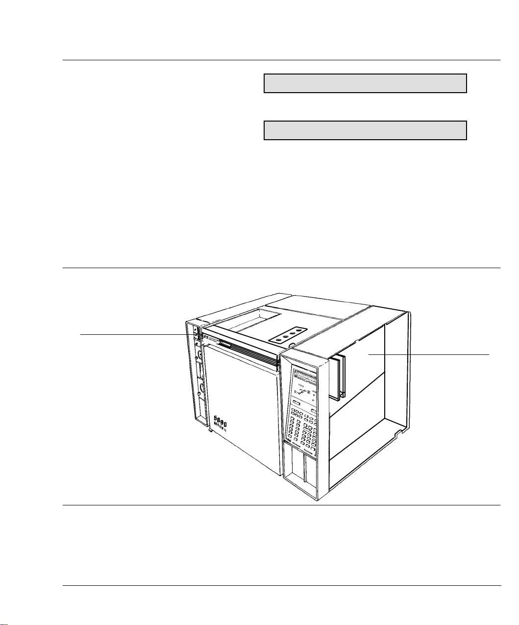
Signal Output
File compatibility with data handling devices
Figure 5-14
GC Displays for File Transfer Modes
How do I change modes?
1. Turn power off.
2. Remove the GC side panel, and locate the main PC board.
Figure 5-15
Top Hinge for Grounding
HP 5890A mode
HP 5890 SERIES II mode
ACTUAL SETPOINT
EMULATION MODE OK
ACTUAL SETPOINT
PASSED SELF TEST
Finding the Main PC Board.
3. Find component P15 on the main PC board.
Main PC Board
95
Page 96

Signal Output
File compatibility with data handling devices
Figure 5-16
Figure 5-17
P5
P6
P15
P2
P3
P13 P12
Main PC Board
Finding component P15 on the Main PC Board.
4. Set the jumper (Part No. 1258•0141)for the proper mode. To avoid
electrostatic damage to the main board, ground yourself to the GC
chassis with an ESD strap, or touch an unpainted area of the oven
such as the door hinge.
HP 5890A mode
HP 5890 SERIES II mode
96
Setting the jumper.
Page 97

Signal Output
File compatibility with data handling devices
How to convert HP 339X Integrator workfiles from 5890A to SERIES II mode:
1. Turn the GC off.
2. Follow the previous instructions to set the GC for 5890A mode (use
proper grounding).
3. Download the workfile from the integrator.
4. Turn GC power off.
5. Remove the P15 jumper. (Now the GC is in SERIES II mode.)
6. Turn GC power on.
7. Add SERIES II setpoints (time table, etc).
8. Store the workfile at the integrator.
STORE
Note: Using
workfiles can be converted with each jumper change sequence.
on the HP 5890 SERIES II, up to 4 integrator
97
Page 98

This page intentionally left blank.
Page 99

6
Inlet Systems
Page 100

Inlet Systems
This chapter provides information for the following HP 5890 SERIES II
(hereafter referred to as HP 5890) inlet systems:
C
Packed column inlet
C
Septum•purgedpacked column inlet
C
Split/splitlesscapillary inlet
For cool on•columninformation, see the manual Programmable Cool
On•ColumnInlet. Maintenance information is provided in Chapter 8,
Preventive Maintenance.
Packed column inlet
The packed column inlet may be used with HP Series 530¿capillary
columns, metal packed or glass packed columns. Additionally, on•column
injection is possible with 1/4•inchglass packed columns. The packed
column inlet is optimized for low to intermediate temperatures
(200-300
^
C).
100
 Loading...