

Page 1

HP 5830 Switch Series
Installation Guide
Abstract
This document guides you through installation of HP A Series products, including installing the device,
connecting to the network, hardware management, and troubleshooting.
Part number: 5998-2058 Version 3
Document version: 6W100-20110720
Page 2

Legal and notice information
© Copyright 2011 Hewlett-Packard Development Company, L.P.
No part of this documentation may be reproduced or transmitted in any form or by any means
without prior written consent of Hewlett-Packard Development Company, L.P.
The information contained herein is subject to change without notice.
HEWLETT-PACKARD COMPANY MAKES NO WARRANTY OF ANY KIND WITH REGARD TO THIS
MATERIAL, INCLUDING, BUT NOT LIMITED TO, THE IMPLIED WARRANTIES OF MERCHANTABILITY
AND FITNESS FOR A PARTICULAR PURPOSE. Hewlett-Packard shall not be liable for errors contained
herein or for incidental or consequential damages in connection with the furnishing, performance, or
use of this material.
The only warranties for HP products and services are set forth in the express warranty statements
accompanying such products and services. Nothing herein should be construed as constituting an
additional warranty. HP shall not be liable for technical or editorial errors or omissions contained
herein.
Page 3

Contents
Preparing for installation ············································································································································· 1
Overview············································································································································································1
Safety recommendations ··················································································································································1
Installation site requirements ···································································································································2
Rack-mounting requirements····································································································································2
Installation tools·································································································································································2
Installing the switch······················································································································································ 3
Confirming installation preparations·······························································································································4
Installing the switch in a 19-inch rack·····························································································································4
Mounting bracket and cable management bracket kits ·······················································································4
Rack mounting rail kit ··············································································································································5
Rack-mounting procedure ········································································································································6
Identifying the mounting position····························································································································6
Installing the mounting brackets, chassis rails, and grounding cable (for the 48G model/48G TAA model)
···················································································································································································7
Installing the mounting brackets, chassis rails, and grounding cable (for the 96G model/96G TAA model)
···················································································································································································9
Rack-mounting the 48G model/48G TAA model switch·················································································· 11
Rack-mounting the 96G model/96G TAA model switch·················································································· 13
Grounding the switch ···················································································································································· 15
Grounding the switch with a grounding strip····································································································· 16
Grounding an AC-powered switch through the PE wire ··················································································· 16
Installing/removing a fan tray ······································································································································ 17
Selecting a fan tray ··············································································································································· 17
Installing a fan tray ··············································································································································· 18
Removing a fan tray·············································································································································· 18
Installing/removing a power supply ···························································································································· 19
Installing a power supply ·····································································································································19
Removing a power supply···································································································································· 20
Connecting the power cord ·········································································································································· 22
Connecting the 650W AC power supply (JC680A) ························································································· 22
Connecting the 650W DC power supply (JC681A) ························································································· 23
Installing/removing an interface card ························································································································· 23
Installing an interface card··································································································································· 23
Removing an interface card ································································································································· 24
Verifying the installation················································································································································ 25
Powering on the switch for the first time···················································································································26
Setting up the configuration environment ···················································································································· 26
Connecting the console cable ······································································································································ 26
Console cable························································································································································ 26
Connection procedure ·········································································································································· 26
Setting terminal parameters ·········································································································································· 27
Powering on the switch·················································································································································· 30
Verification before power-on ·······························································································································30
Powering on the switch········································································································································· 30
Setting up an IRF fabric ·············································································································································32
IRF fabric setup flowchart·············································································································································· 32
iii
Page 4

Planning IRF fabric setup··············································································································································· 33
Identifying the master switch and planning IRF member IDs ············································································ 33
Planning IRF topology and connections·············································································································· 34
Identifying physical IRF ports on the member switches ····················································································· 35
Planning the cabling scheme ·······························································································································35
Configuring basic IRF settings······································································································································· 37
Connecting the physical IRF ports ································································································································ 37
Accessing the IRF fabric to verify the configuration ··································································································· 37
Maintenance and troubleshooting····························································································································39
Power supply failure ······················································································································································ 39
Fan failure······································································································································································· 39
Configuration terminal problems·································································································································· 39
Support and other resources ·····································································································································41
Contacting HP ································································································································································ 41
Subscription service ·············································································································································· 41
Related information························································································································································ 41
Documents······························································································································································ 41
Websites································································································································································· 41
Conventions ···································································································································································· 42
Appendix A Technical specifications························································································································44
Technical specifications················································································································································· 44
Panel views ····································································································································································· 45
48G model/48G TAA model panel views ········································································································ 45
96G model/96G TAA model panel views ········································································································ 46
Cooling system ······························································································································································· 47
Cooling system of the 48G model/48G TAA model························································································ 47
Cooling system of the 96G model/96G TAA model························································································ 49
Appendix B FRUs and compatibility matrixes··········································································································50
Hardware compatibility matrix····································································································································· 50
Hot swappable power supplies···································································································································· 50
Hot swappable fan trays··············································································································································· 51
Interface cards································································································································································ 52
Appendix C Ports and LEDs ······································································································································53
Ports ················································································································································································· 53
Console port ··························································································································································53
Management Ethernet port··································································································································· 53
10/100/1000Base-T Ethernet port ···················································································································· 53
SFP port ·································································································································································· 54
SFP+ port································································································································································ 56
LEDs ················································································································································································· 58
System status LED··················································································································································· 58
10/100/1000Base-T Ethernet port LED············································································································· 58
SFP port LED··························································································································································· 58
SFP+ port LED ························································································································································ 59
Management Ethernet port LEDs·························································································································· 59
Interface card status LED······································································································································· 59
Index ···········································································································································································60
iv
Page 5

Preparing for installation
Overview
The HP 5830 Switch Series includes the models in Table 1:
Table 1 Models in the HP 5830 Switch Series
Product code HP description RMN Alias
JC691A
JG316A
JC694A 96G Model Switch BJNGA-AC0002 5830AF-96G
JG374A 96G TAA-compliant Model Switch BJNGA-AC0002 5830AF-96G TAA
IMPORTANT:
For regulatory identification purposes, the switches are assigned RMN. These regulatory numbers
should not be confused with the marketing name HP 5830AF, or the product numbers JC691A,
JG316A, JC694A, and JG374A.
48G Model Switch with 1
Interface Slot
48G TAA-compliant Model Switch
with 1 Interface Slot
Safety recommendations
WARNING!
Read all of the safety instructions in the
installation and operation.
This section provides general recommendations. For more information see the Compliance and Safety
Guide included with your device.
Compliance and Safety Gui
BJNGA-AC0001 5830AF-48G
BJNGA-AC0001 5830AF-48G TAA
de supplied with your device before
• Turn off all the power and remove all the power cables before opening the chassis.
• Unplug all power and external cables before moving the chassis.
• Locate the emergency power off switch before installation and shut off power immediately if
necessary.
• Always wear an ESD-preventive wrist strap when installing the device.
• Do not stare into the open optical interface; the high power density light can burn the retina.
• Use a good grounding system to protect your device against lightning shocks, interferences, and
ESD; this is essential to the operating reliability of your switch.
• Make sure the resistance between the chassis and the ground is less than 1 ohm.
1
Page 6

Installation site requirements
This section provides information about temperature and humidity, cleanness, and air quality
requirements.
You must maintain a proper temperature and humidity in the equipment room. Long-term high
humidity may lead to bad insulation, electricity leakage, mechanical property changes, and metal
corrosion. However, if the relative humidity is too low, captive screws may become loose as the result
of contraction of insulation washers and static electricity may be produced in a dry environment to
jeopardize the circuits. High temperature is the most undesirable condition, because it accelerates the
aging of insulation materials and significantly lowers the reliability and service life of the switch.
For the temperature and humidity requirements of different switch models, see Table 9 in Appendix A
T
echnical specifications.
Table 2 Dust concentration limit in the equipment room
Substance Concentration limit (particles/m
Dust particles
NOTE:
Dust particle diameter ≥ 5 μm
≤ 3 x 10⁴
(No visible dust on desk in three days)
Table 3 Limits on harmful gases in the equipment room
Gas Maximum concentration (mg/m
SO
2
H2S 0.06
NH
3
Cl
2
0.2
0.05
0.01
Rack-mounting requirements
Before rack-mounting a switch, make sure the rack meets the following requirements:
• HP recommends that you mount a switch in an open rack. If you mount a switch in a closed rack,
make sure there is a good heat dissipation system.
3
)
3
)
• Make sure the rack is steady enough to support the switch and accessories.
• Make sure the switch fits the rack size. Leave some spaces beside the left and right panels of the
switch for chassis heat dissipation.
Installation tools
• Phillips screwdriver P1-100mm, P2-150mm, and P3-250mm
• ESD-preventive wrist strap
All these installation tools are user supplied.
2
Page 7
Installing the switch
CAUTION:
Keep the tamper-proof seal on a mounting screw on the chassis cover intact. If you want to open the
chassis, contact HP for permission. Otherwise HP shall not be liable for any consequence.
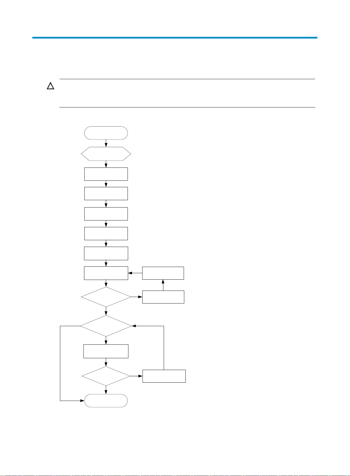
Figure 1 Hardware installation flow
Start
Install to a
specified
position
Ground the switch
Install a fan tray
Connect the power
No
Install an interface
Install a power
module
cord
Verify the
installation
Power on the
switch
Operating
properly?
Yes
card?
Yes
Verify the
installation
Operating
properly?
Troubleshoot the
No
Power off the
No
Troubleshoot the
switch
switch
switch
Yes
End
3
Page 8
NOTE:
When you install a 96G model or 96G TAA model switch, skip the procedure for installing an
expansion interface card. The switch does not support expansion interface cards.
Confirming installation preparations
Before you install the switch, make sure:
• You have read "Preparing for installation" carefully and the installation site meets all the
requirements.
• A 19-inch rack is ready for use. For how to install a rack, see the rack installation guide.
Installing the switch in a 19-inch rack
Mounting bracket and cable management bracket kits
Table 4 Mounting bracket and cable management bracket kits
Switch models Mounting brackets
One pair of 1U
48G model/48G
TAA model
96G model/96G
TAA model
mounting brackets
(supplied with the
switch)
One pair of 2U
mounting brackets
(supplied with the
switch)
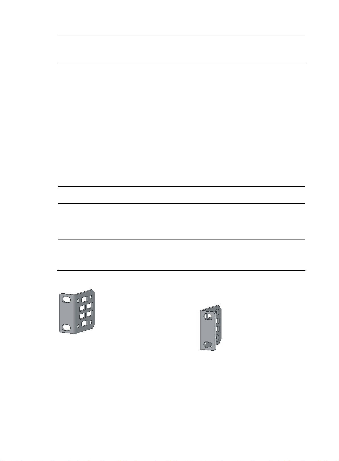
Figure 2 1U mounting bracket kit
Cable management
brackets
N/A See Figure 2.
One pair (supplied with
the switch)
Bracket view
The mounting brackets and
cable management brackets
are secured together by
default (see Figure 3).
4
Page 9
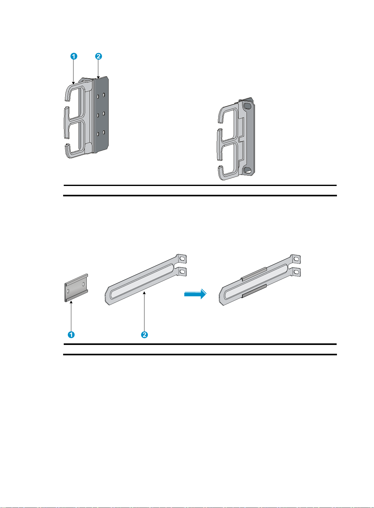
Figure 3 2U cable management bracket and mounting bracket kit
(1) Cable management bracket (2) Mounting bracket
Rack mounting rail kit
The switches come with a pair of chassis rails and a pair of slide rails.
Figure 4 Chassis rail and slide rail kit for the 48G model/48G TAA model
(1) Chassis rail (2) Slide rail
The slide rails supplied with a 48G model or 48G TAA model switch are short. You can order a pair
of long slide rails depending on your rack depth. For more information, see Table 6
.
5
Page 10
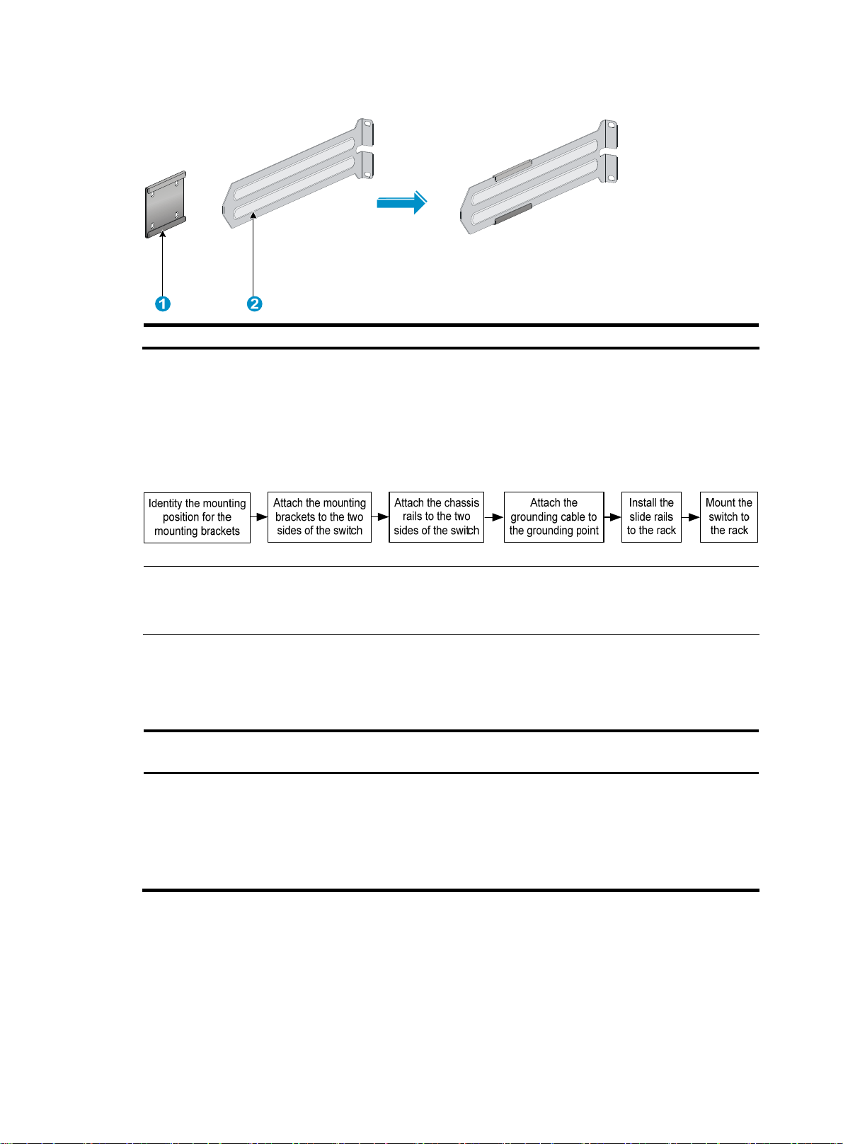
Figure 5 Chassis rail and slide rail kit for the 96G model/96G TAA model
(1) Chassis rail (2) Slide rail
Rack-mounting procedure
You can install a switch in a 19-inch rack using different mounting positions. Figure 6 shows the rackmounting procedure.
Figure 6 Rack-mounting procedure
NOTE:
If a rack shelf is available, you can put the switch on the rack shelf, slide the switch to an appropriate
location, and fix the switch to the rack with the mounting brackets.
Identifying the mounting position
Table 5 Mounting positions
Mounting bracket
position
• Rear mounting
(near the power
supplies)
• Front mounting
(near the network
ports)
To mount the switch securely in a rack, use slide rails and chassis rails in addition to the mounting
brackets.
Installing the mounting brackets, chassis
rails, and grounding cable
See "Installing the mounting brackets, chassis
rai
ls, and grounding cable (for the 48G
model/48G TAA model)."
See "Installing the mounting brackets, chassis
rai
ls, and grounding cable (for the 96G
model/96G TAA model)."
Installing the switch
See "Rack-mounting the 48G
model/48G TA
See "Rack-mounting the 96G
model/96G TA
A model switch."
A model switch."
6
Page 11
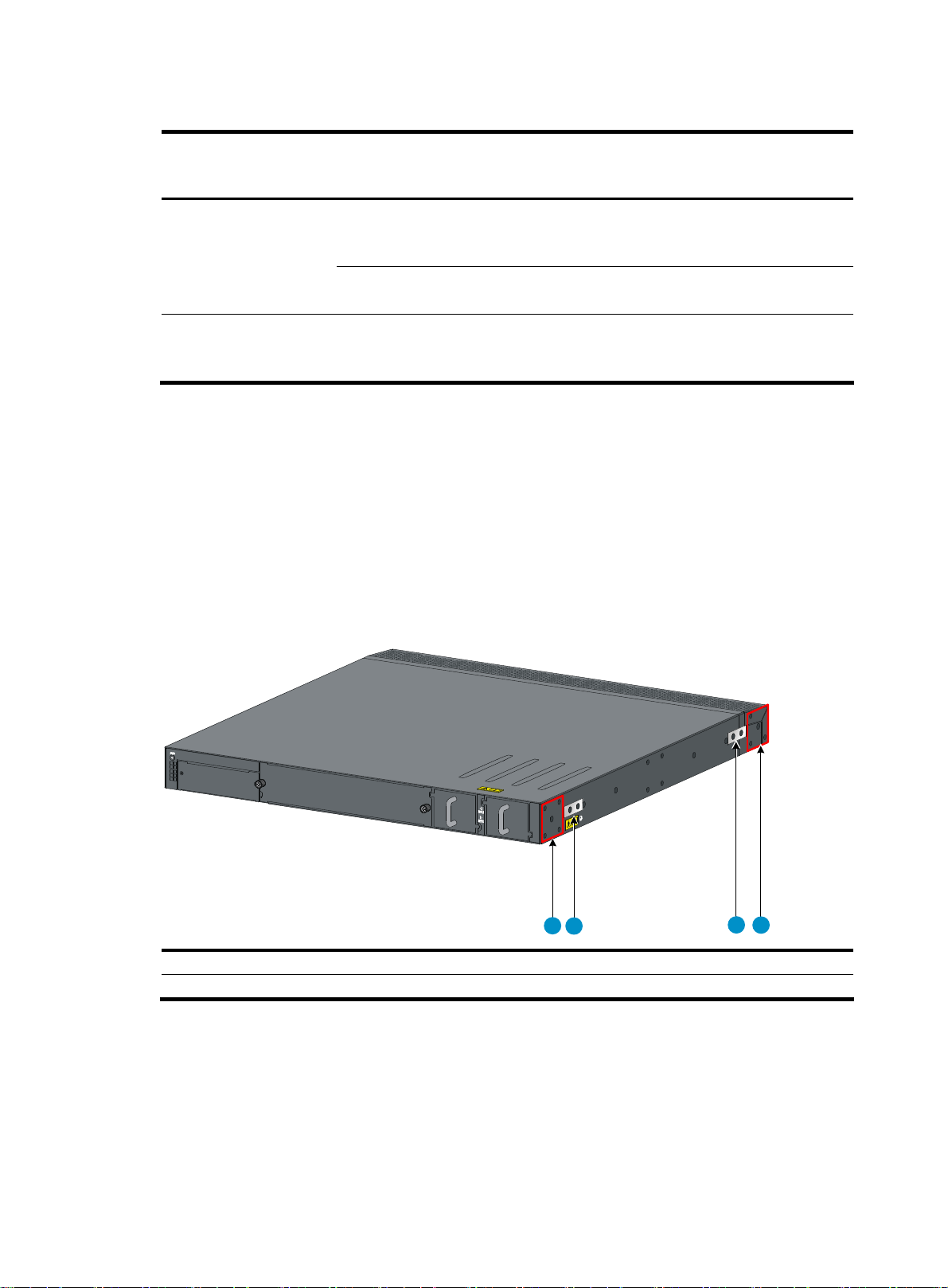
Table 6 Minimum and maximum distances required between front and rear rack posts
Switch model Mounting accessories
Mounting brackets and
48G model/48G TAA
model
96G model/96G TAA
model
short slide rails (supplied
with the switch)
Mounting brackets and
long slide rails (optional)
Mounting brackets and
slide rails (supplied with
the switch)
Minimum distance
between front and
rear rack posts
401 mm (15.79 in) 654 mm (25.75 in)
621 mm (24.45 in) 874 mm (34.41 in)
489 mm (19.25 in) 993 mm (39.09 in)
Maximum distance
between front and
rear rack posts
Installing the mounting brackets, chassis rails, and grounding cable (for the 48G model/48G TAA model)
Each of the 48G model and 48G TAA model switches has one front mounting position near the
network ports and one rear mounting position near the power supplies. The switch also has one
primary grounding point with a grounding sign and one auxiliary grounding point. Use the primary
grounding point in most situations. If the primary grounding point fails or is not suitable for the
installation site, use the auxiliary grounding point.
Figure 7 Identifying the mounting and grounding positions
1
2
(1) Rear mounting position (2) Primary grounding point
(3) Auxiliary grounding point (4) Front mounting position
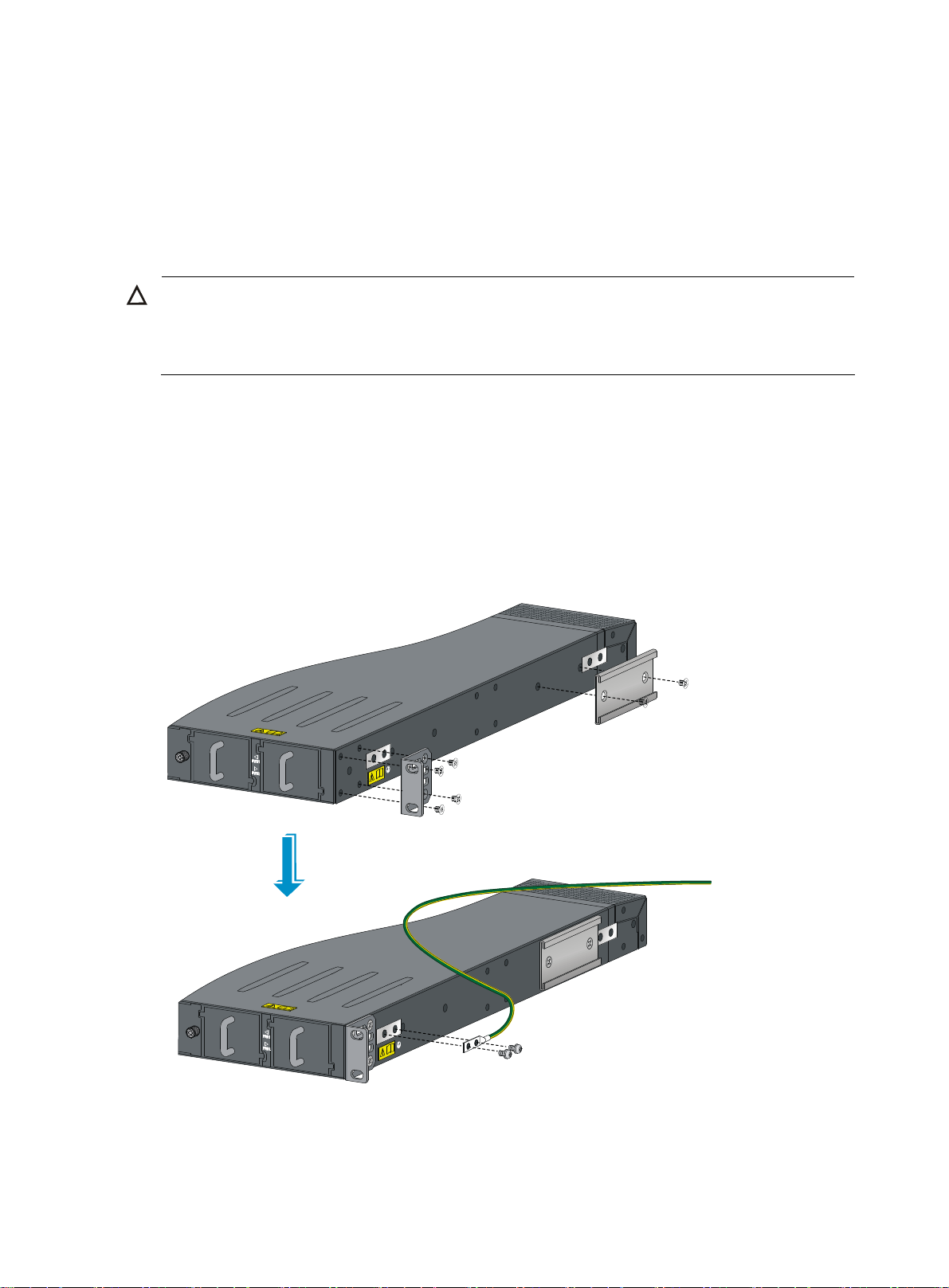
Attaching the mounting brackets and chassis rails to the switch chassis
Use the following procedure for both sides of the chassis.
3
4
To attach the mounting brackets and chassis rails to the switch chassis:
1. Align the mounting brackets with the screw holes in the rear mounting position (see Figure 8) or
front mounting position (see Figure 9).
2. Use M4 screws supplied with the switch to fix the mounting brackets to the chassis.
7
Page 12
If the mounting brackets are in the rear mounting position, align the chassis rails with the screw
3.
holes at the front of the side panels (see Figure 8). If th
mounting position, align the chassis rails with the screw holes at the rear of the side panels (see
Figure 9).
4. Use M4 screws (supplied with the switch) to fix the chassis rails to the chassis.
Connecting the grounding cable to the switch chassis
CAUTION:
The primary grounding point and auxiliary grounding point are located on the left side panel. If you
use either of the grounding points, you must connect the grounding cable to the grounding point before
you mount the switch in the rack.
To connect the grounding cable to a chassis grounding point:
1. Select a grounding point, for example, the primary grounding point.
2. Remove the grounding screws from the primary grounding point. (You can use the screws for
connecting to the primary grounding point or the auxiliary grounding point.)
3. Align the two-hole grounding lug at one end of the cable with the grounding holes of the
grounding point, insert the grounding screws into the holes, and tighten the screws with a
screwdriver to fix the grounding lug to the chassis, as shown in Figure 8.
e mounting brackets are in the front
Figure 8 Attaching th
e rear mounting brackets, chassis rails, and the grounding cable to the chassis
8
Page 13
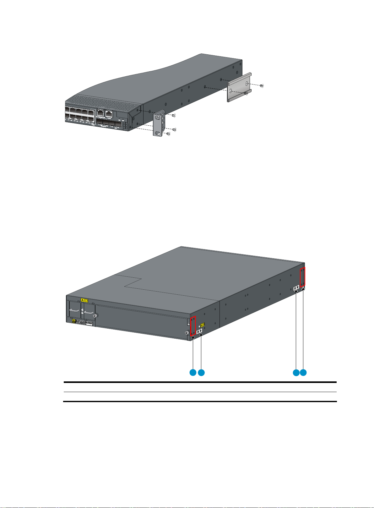
Figure 9 Attaching the front mounting brackets and the chassis rails to the chassis
Installing the mounting brackets, chassis rails, and grounding cable (for the 96G model/96G TAA model)
Each of the 96G model and 96G TAA model switches has one front mounting position near the
network ports and one rear mounting position near the power supplies. The switch also has one
primary grounding point with a grounding sign and one auxiliary grounding point. You use the
primary grounding point in most situations. If the primary grounding point fails or is not suitable for
the installation site, use the auxiliary grounding point.
Figure 10 Identifying the mounting and grounding positions
1
2
(1) Rear mounting position (2) Primary grounding point
(3) Auxiliary grounding point (4) Front mounting position
Attaching the mounting brackets and chassis rails to the switch chassis
4
3
Use the following procedure for both sides of the chassis.
To attach the mounting brackets and chassis rails to the switch chassis:
1. Align the mounting brackets with the screw holes in the rear mounting position (see Figure 11)
or front mounting position (see Figure 12).
9
Page 14
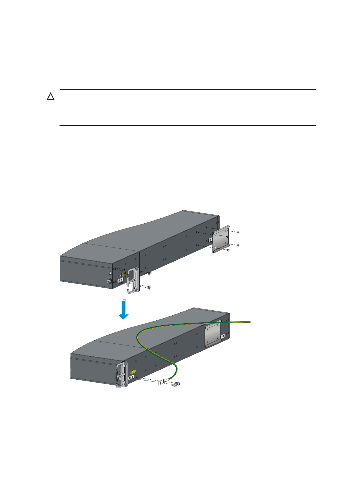
Use M4 screws supplied with the switch to fix the mounting brackets to the chassis.
2.
3. Align the chassis rails with the screw holes at the side panels (see Figure 11 and Figure 12).
4. Use M4 screws supplied with the switch to fix the chassis rails to the chassis.
Connecting the grounding cable to the switch chassis
CAUTION:
The primary grounding point and auxiliary grounding point are located on the left side panel. If you
use either of the grounding points, you must connect the grounding cable to the grounding point before
you mount the switch in the rack.
To connect the grounding cable to a chassis grounding point:
1. Choose a grounding point, for example, the primary grounding point.
2. Unpack the grounding cable and the grounding screws. (You can use the cable and screws for
connecting to the primary grounding point or the auxiliary grounding point.)
3. Align the two-hole grounding lug at one end of the cable with the grounding holes of the
grounding point, insert the grounding screws into the holes, and tighten the screws with a
screwdriver to fix the grounding lug to the chassis, as shown in Figure 11.
Figure 11 Attaching th
e rear mounting brackets, chassis rails, and the grounding cable to the chassis
10
Page 15

Figure 12 Attaching the front mounting brackets and the chassis rails to the chassis
Rack-mounting the 48G model/48G TAA model switch
To attach the slide rails to the rack:
1. Identify the rack attachment position for the slide rails.
2. Install cage nuts (user-supplied) in the mounting holes in the rack posts.
3. Align the screw holes in one slide rail with the cage nuts in the rack post on one side, and use
screws (user-supplied) to fix the slide rail to the rack, as shown in Figure 13.
4. Repeat the preceding step to attach the other slide rail to the rack post on the other side. Keep
the two slide rails at the same height so the slide rails can fit into the chassis rails.
Figure 13 Installing the slide rails
Mounting the switch on the rack requires two persons.
To mount the switch in the rack:
1. Wear an ESD-preventive wrist strap and make sure it makes good skin contact and is well
grounded.
11
Page 16

Verify that the mounting brackets and chassis rails have been securely fixed on the two sides of
2.
the switch.
3. Verify that the slide rails have been correctly attached to the rack posts.
4. Install cage nuts (user-supplied) to the front rack posts and make sure they are at the same level
as the slide rails.
5. Supporting the bottom of the switch, align the chassis rails with the slide rails on the rack posts,
as shown in Figure 14. Wo
rk with another person to slide the chassis rails along the slide rails
until the mounting brackets flush with the rack posts.
6. Use appropriate screws to fix the mounting brackets to the rack, as shown in Figure 15. Make
sure the front ends of the slide rails reach out of the chassis rails, as shown in callout 1 in
Figure 15.
Figure 14 Mounting the
switch in the rack (I)
12
Page 17

Figure 15 Mounting the switch in the rack (II)
Rack-mounting the 96G model/96G TAA model switch
To attach the slide rails to the rack:
1. Identify the rack attachment position for the slide rails.
2. Install cage nuts (user-supplied) in the mounting holes in the rack posts.
3. Align the screw holes in one slide rail with the cage nuts in the rack post on one side, and use
screws (user-supplied) to fix the slide rail to the rack, as shown in Figure 16.
4. Repeat the preceding steps to attach the other slide rail to the rack post on the other side. Keep
the two slide rails at the same height so the slide rails can fix into the chassis rails.
13
Page 18

Figure 16 Installing the slide rails
Mounting the switch to the rack requires two persons.
To mount the switch to the rack:
1. Wear an ESD-preventive wrist strap and make sure it makes good skin contact and is well
grounded.
2. Verify that the mounting brackets and chassis rails have been securely fixed on the two sides of
the switch.
3. Verify that the slide rails have been correctly attached to the rack posts.
4. Install cage nuts (user-supplied) to the front rack posts and make sure they are at the same level
as the slide rails.
5. Supporting the bottom of the switch, align the chassis rails with the slide rails on the rack posts,
as shown in Figure 17. Wo
rk with another person to slide the chassis rails along the slide rails
until the mounting brackets flush with the rack posts.
6. Use appropriate screws to fix the mounting brackets to the rack, as shown in Figure 18. To
ensure steadiness of the switch in the rack, make sure the front ends of the slide rails reach out
of the chassis rails, as shown in callout 1 in Figure 18.
14
Page 19

Figure 17 Mounting the switch in the rack (I)
Figure 18 Mounting the switch in the rack (II)
Grounding the switch
WARNING!
Correctly connecting the switch grounding cable is crucial to lightning protection and EMI protection.
15
Page 20

The power input end of the switch has a noise filter, whose central ground is directly connected to the
chassis to form the chassis ground (commonly known as PGND). You must securely connect this
chassis ground to the earth so the faradism and leakage electricity can be safely released to the earth
to minimize EMI susceptibility of the switch.
You can ground the switch using one of the following methods, depending on the grounding
conditions available at the installation site:
• Grounding the switch with a grounding strip
• Grounding an AC-powered switch through the PE wire
T
he power and grounding terminals in this section are for illustration only.
Grounding the switch with a grounding strip
1. Attach the two-hole grounding lug at one end of the grounding cable to a grounding point on
the switch chassis.
{ 48G model and 48G TAA model: see "Connecting the grounding cable to the switch chassis."
{ 96G model and 96G TAA model: See "Connecting the grounding cable to the switch chassis."
2. Connect the OT terminal at the other end of the grounding cable to a grounding post on the
grounding strip, and fasten the grounding cable to the grounding post with a hex nut.
Figure 19 Connecting the grounding cable to a grounding strip
1
(1) Hex nut (2) OT terminal
(3) Grounding post (4) Grounding strip
2
3
4
Grounding an AC-powered switch through the PE wire
If you ground an AC-powered switch through the PE wire of the power cable, make sure the following
conditions are met:
• The power cable is a three-wire power cable that has a PE terminal.
• The ground contact in the power outlet is securely connected to the ground in the power
distribution room or on the AC transformer side.
16
Page 21

• The power cable is securely connected to the power outlet.
Figure 20 Grounding through the PE wire of an AC power cable
Installing/removing a fan tray
CAUTION:
The switches have only one fan tray slot. To ensure good ventilation, make sure these conditions are
met:
• Do not operate the switch without a fan tray.
• If the JC692A or JC693A fan tray has problems during operation, replace it within 8 minutes while
the switch is operating.
• If the JC695A or JC696A fan tray has problems during operation, replace it within 6 minutes while
the switch is operating.
• If you fail to replace the fan tray within the time limit, the switch generates alarms, the system LED
flashes red, and the switch might be damaged.
Selecting a fan tray
The switches provide two types of fan trays with different airflow directions: from power side to port
side and from port side to power side. Before you install a fan tray, check the airflow direction
labeled on the fan tray and make sure the airflow of the chassis is appropriate to the installation site.
When the switch is started up, the system records the airflow direction of the fan tray. After you
replace the fan tray when the switch is operating, if the airflow direction of the new fan tray is not the
same as the old one, the system displays the following trap and log information:
System fan airflow direction is not preferred on slot x, please check it.
If you confirm that the airflow direction of the new fan tray is correct, use the fan prefer-direction slot
slot-number { power-to-port | port-to-power } command in system view to change the preferred
airflow direction.
For more information about the cooling system and fan tray specifications of the switch, see "Cooling
sys
tem" and "Table 13."
F
or more information about the fan prefer-direction slot command, see HP 5830 Switch Series
Fundamentals Command Reference.
17
Page 22

Installing a fan tray
1. Wear an ESD-preventive wrist strap and make sure it makes good skin contact and is well
grounded.
2. Loosen the captive screws on the filler panel to remove the filler panel.
3. Unpack the fan tray and check that the fan tray model is correct.
4. Grasp the handle of the fan tray with one hand and support the fan tray bottom with the other,
and slide the fan tray along the guide rails into the slot until the fan tray seats in the slot and
has a firm contact with the backplane (see callout 1 in Figure 21 or Figure 22). T
damage to the fan tray or the connectors on the backplane, insert the fan tray gently. If you
encounter resistance while inserting the fan tray, pull out the fan tray and insert it again.
5. Fasten the captive screw on the fan tray with a Philips screwdriver until the fan tray is securely
fastened into the chassis (see callout 2 in Figure 21 or Figure 22). If the captive s
be tightly secured, check the installation of the fan tray.
Figure 21 Installing a fan tray (for the 48G model/48G TAA model)
o prevent
crew cannot
Figure 22 Installing a fan tray (for the 96G model/96G TAA model)
Removing a fan tray
18
Page 23

WARNING!
Take out the fan tray after the fans completely stop rotating. To avoid an unbalanced fan causing loud
noise, do not touch the fans, even if they are not rotating.
To remove a fan tray:
1. Wear an ESD-preventive wrist strap and make sure it makes good skin contact and is well
grounded.
2. Loosen the captive screw of the fan tray with a Philips screwdriver until it is fully disengaged
from the switch chassis.
3. Grasp the handle of the fan tray with one hand and pull the fan tray part way out the slot.
Support the fan tray bottom with the other hand, and pull the fan tray slowly along the guide
rails out of the slot. Put the removed fan tray in an antistatic bag for future use.
Installing/removing a power supply
The switches come with both power supply slots covered by filler modules. You can install one or two
power supplies as needed. For more information about the power supplies available for the switches,
see "Appendix B FRUs and compatibility matrixes."
Installing a power supply
1. Wear an ESD-preventive wrist strap and make sure it makes good skin contact and is well
grounded.
2. Remove the power filler module from the power supply slot.
3. Unpack the power supply and check that the power supply model is correct.
4. Correctly orient the power supply with the power supply slot (see Figure 23 and Figure 24),
grasp the handle of the module with one hand and support the module bottom with the other,
and slide the module slowly along the guide rails into the slot. Follow the forward inertia of the
power supply when inserting it into the chassis to ensure that the power supply has firm contact
with the connectors on the backplane.
5. To prevent damage to the connectors inside the switch chassis, insert the power supply gently. If
you encounter resistance while inserting the power supply, pull out the power supply and insert
it again. If you cannot insert the power supply into the slot, re-orient the power supply rather
than use excessive force to push it in.
Figure 23 Installing a power supply (for the 48G model/48G TAA model)
19
Page 24

Figure 24 Installing a power supply (for the 96G model/96G TAA model)
Removing a power supply
CAUTION:
If the switch has two power supplies, removing one power supply does not affect the operation of the
switch. If the switch has only one power supply, removing the power supply powers off the switch.
To remove a power supply:
1. Wear an ESD-preventive wrist strap and make sure it makes good skin contact and is well
grounded.
2. Remove the power cord from the power supply.
{ If the power supply is AC powered, directly unplug the power cord.
{ If the power supply is DC powered, squeeze the tabs on the power cord connector with your
thumb and forefinger and pull the connector out, as shown in Figure 25.
3. Hold the handle on the power supply with one hand, pivot the latch on the power supply with
your thumb, and pull the power supply part way out of the slot, as shown in Figure 26 and
Figure 27.
4. Supporting the power supply bottom with one hand, slowly pull the power supply out with the
other hand. Put the removed power supply in an antistatic bag for future use.
5. If no power supply is to be installed, install the power filler module.
20
Page 25

Figure 25 Removing the DC power cord
(1) Press the tabs on the power cord connector with your thumb
and forefinger
(2) Pull the power cord connector out
Figure 26 Removing the power supply (for the 48G model/48G TAA model)
(1) Pivot the latch to the right with your thumb (2) Pull the power supply out
21
Page 26

Figure 27 Removing the power supply (for the 96G model/96G TAA model)
(1) Pivot the latch up with your thumb (2) Pull the power supply out
Connecting the power cord
Connecting the 650W AC power supply (JC680A)
1. Insert the female connector of the AC power cord supplied with the power supply into the AC-
input power receptacle of the power supply.
2. Use a cable tie to secure the power cord to the handle of the power supply, as shown in Figure
28.
3. Connect the other end of the power cord to an AC power outlet.
Figure 28 Connecting the 650W AC power supply (JC680A)
(1) Cable tie
(2) Tighten the cable tie to secure the power cord to the handle of the power supply
22
Page 27

Connecting the 650W DC power supply (JC681A)
1. Unpack the DC power cord, identify the plug for connecting to the power supply, orient the
plug with the power receptacle on the power supply, and insert the plug into the receptacle
(see Figure 29).
If you cann
force to push it in.
2. Use a cable tie to secure the power cord to the handle of the power supply, as shown in Figure
28.
3. Connect the other end of the power cord to the DC power source.
Figure 29 Connecting the 650W DC power supply (JC681A)
ot insert the plug into the receptacle, re-orient the plug rather than use excessive
Installing/removing an interface card
CAUTION:
• Do not touch the surface-mounted components directly with your hands.
• Do not use excessive force during the operation.
Each of the 48G model and 48G TAA model switches provides an expansion interface slot covered
with a filler panel. For the interface cards available for the switches, see "Appendix B FRUs and
co
mpatibility matrixes."
Installing an interface card
1. Wear an ESD-preventive wrist strap and make sure it makes good skin contact and is well
grounded.
2. Loosen the mounting screws on the filler panel over the interface card slot at the front panel with
a Phillips screwdriver and remove the filler panel. Keep the removed filler panel for future use.
23
Page 28

Figure 30 Removing the filler panel over an interface card slot
3. Unpack the interface card. Gently push the interface card in along the slot guide rails until the
interface card has close contact with the switch.
4. Tighten the captive screws with a Phillips screwdriver to fix the interface card.
Figure 31 Installing an interface card
(1) Slide the interface card into the slot (2) Tighten the captive screws
Removing an interface card
1. Wear an ESD-preventive wrist strap and make sure it makes good skin contact and is well
grounded.
2. Use a Phillips screwdriver to loosen the captive screws at both sides of the interface card
completely.
3. Pull the interface card along the guide rails until it completely comes out of the switch chassis.
4. If no new card is to be installed, install the filler panel to prevent dust and ensure good
ventilation in the switch.
Figure 32 Remove an interface card
1
1
2
(1) Loosen the captive screws (2) Pull the interface card out of the slot
24
Page 29

Verifying the installation
Before you power on the switch, verify the following items are in place:
• There is enough space for heat dissipation around the switch, and the rack is stable.
• The grounding cable is securely connected.
• The correct power source is used.
• The power cords are properly connected.
25
Page 30

Powering on the switch for the first time
Setting up the configuration environment
To set up the configuration environment, connect a terminal (a PC in this example) to the console port
on the switch with a console cable.
Figure 33 Network diagram for configuration environment setup
Connecting the console cable
Console cable
A console cable is an 8-core shielded cable, with a crimped RJ-45 connector at one end for
connecting to the console port of the switch, and a DB-9 female connector at the other end for
connecting to the serial port on the console terminal.
Figure 34 Console cable
Connection procedure
To connect a terminal device to the switch:
1. Identify the mark on the console port and make sure you are connecting to the correct port.
26
Page 31

Plug the DB-9 female connector of the console cable to the serial port of the console terminal or
2.
PC.
3. Connect the RJ-45 connector to the console port of the switch.
NOTE:
• The serial port on a PC does not support hot swapping. When you connect a PC to a powered-on
switch, connect the DB-9 connector of the console cable to the PC before connecting the RJ-45
connector to the switch.
• When you disconnect a PC from a powered-on switch, disconnect the DB-9 connector of the console
cable from the PC after disconnecting the RJ-45 connector from the switch.
Setting terminal parameters
To configure and manage the switch, you must run a terminal emulator program on the console
terminal, for example, a PC. This section uses Windows XP HyperTerminal as an example.
The following are the required terminal settings:
• Bits per second—9600
• Data bits—8
• Parity—None
• Stop bits—1
• Flow control—None
• Emulation—VT100
To set terminal parameters, for example, on a Windows XP HyperTerminal:
1. Select Start > All Programs > Accessories > Communications > HyperTerminal.
The Connection Description dialog box appears.
2. Enter the name of the new connection in the Name field and click OK.
Figure 35 Connection description
27
Page 32

Select the serial port to be used from the Connect using list, and click OK.
3.
Figure 36 Setting the serial port used by the HyperTerminal connection
4. Set Bits per second to 9600, Data bits to 8, Parity to None, Stop bits to 1, and Flow control to
None, and click OK.
Figure 37 Setting the serial port parameters
5. Select File > Properties in the HyperTerminal window.
28
Page 33

Figure 38 HyperTerminal window
6. On the Settings tab, set the emulation to VT100, and click OK.
Figure 39 Setting terminal emulation in Switch Properties dialog box
29
Page 34

Powering on the switch
Verification before power-on
Before powering on the switch, verify that:
• The power cord is properly connected.
• The input power voltage meets the requirement of the switch.
• The console cable is properly connected, the terminal or PC used for configuration has started,
and the configuration parameters have been set.
Powering on the switch
Power on the switch (for example, an 5830AF-48G switch), and you can see the following
information:
System is starting...
Booting Normal Extend BootWare....
The Extend BootWare is self-decompressing.....................Done!
****************************************************************************
* *
* HP A5830AF BootWare, Version 1.03 *
* *
****************************************************************************
Copyright (c) 2010-2011 Hewlett-Packard Development Company, L.P.
Compiled Date : Feb 22 2011
CPU Type : XLS208
CPU L1 Cache : 32KB
CPU Clock Speed : 750MHz
Memory Type : DDR2 SDRAM
Memory Size : 1024MB
Memory Speed : 533MHz
BootWare Size : 1024KB
Flash Size : 64MB
CPLD Version : 002
PCB Version : Ver.B
BootWare Validating...
Press Ctrl+B to enter extended boot menu...
Starting to get the main application file--flash:/main.bin!............
............................................................................
......................
The main application file is self-decompressing.............................
............................................................................
............................................................................
............................................................................
............................................................................
30
Page 35

............................................................................
............................................................................
............................................................................
............................................................................
..Done!
The oam application file is self-decompressing..............................
............................................................................
............................................................................
.................................................................Done!
System application is starting...
User interface aux0 is available.
Press ENTER to get started.
Press Enter at the prompt. When the prompt <HP> appears, you can configure the switch.
For more information about the configuration commands and CLI, see HP 5830 Switch Series
Configuration Guides and HP 5830 Switch Series Command References.
31
Page 36

Setting up an IRF fabric
You can use HP IRF technology to connect and virtualize the switches into a virtual switch called an
"IRF fabric" or "IRF virtual device" for flattened network topology, and high availability, scalability,
and manageability.
IRF fabric setup flowchart
Figure 40 IRF fabric setup flowchart
Start
Plan IRF fabric setup
Install IRF member switches
Connect the grounding cable
and power cords
Power on the switches
Configure basic IRF settings
Connect the physical IRF ports
Slave switches reboot and the
IRF fabric is automatically
established
End
To set up an IRF fabric:
32
Page 37

Step Description
Plan the installation site and IRF fabric setup parameters. Complete the
following tasks:
• Planning IRF fabric setup
1. Plan IRF fabric setup.
• Identifying the master switch and planning IRF member IDs
• Planning IRF topology and connections
• Identifying physical IRF ports on the member switches
• Planning the cabling scheme
2. Install IRF member
switches.
3. Connect ground wires
and power cords.
See "Setting up an IRF fabric."
See "Grounding the switch" a
nd "Connecting the power cord."
4. Power on the switches.
5. Configure basic IRF
settings.
6. Connect the physical
IRF ports.
N/A.
See HP 5830 Switch Series IRF Configuration Guide.
Connect the physical IRF ports on the switches. Use SFP+ transceiver modules
and fibers to connect 10-Gigabit SFP+ ports over a long distance, or use
SFP+ cables to connect 10-Gigabit SFP+ ports over a short distance.
All switches except the master switch automatically reboot, and the IRF fabric
is established.
Planning IRF fabric setup
To plan for IRF fabric size and the installation site, choose the switch models and identify the number
of required IRF member switches, depending on the user density and upstream bandwidth
requirements. The switching capacity of an IRF fabric equals the total switching capacities of all
member switches.
As your business grows, you can plug a switch into an IRF fabric to increase the switching capacity
without any topology change or replacement.
Plan the installation site depending on your network solution, as follows:
• Place all IRF member switches in one rack for centralized high-density access.
• Distribute the IRF member switches in different racks to implement the ToR access solution for a
data center.
Identifying the master switch and planning IRF member IDs
Determine which switch you want to use as the master for managing all member switches in the IRF
fabric. An IRF fabric has only one master switch. You configure and manage all member switches in
the IRF fabric at the command line interface of the master switch.
NOTE:
IRF member switches will automatically elect a master. You can affect the election result by assigning a
high member priority to the intended master switch. For more information about master election, see
5830 Switch Series IRF Configuration Guide
.
33
HP
Page 38

Prepare an IRF member ID assignment scheme. An IRF fabric uses member IDs to uniquely identify
and manage its members, and you must assign each IRF member switch a unique member ID.
Planning IRF topology and connections
You can create an IRF fabric in daisy chain topology, or more reliably, ring topology. In ring topology,
the failure of one IRF link does not cause the IRF fabric to split as in daisy chain topology. Rather, the
IRF fabric changes to a daisy chain topology without interrupting network services.
You connect the IRF member switches through IRF ports, the logical interfaces for the connections
between IRF member switches. Each IRF member switch has two IRF ports: IRF-port 1 and IRF-port 2.
An IRF port goes up when you bind the first member physical port to it.
When connecting IRF member switches, you must connect the physical ports of IRF-port 1 on one
switch to the physical ports of IRF-port 2 on its neighbor switch.
The switches can provide 10-GE IRF connections through SFP+ ports, and you can bind several SFP+
ports to an IRF port for increased bandwidth and availability.
NOTE:
• Figure 41 an
d Figure 42 show the topologies for an IRF fabric made up of three 48G model switches
for IRF connections.
• The IRF port connections in the two figures are for illustration only, and more connection methods are
available.
Figure 41 IRF fabric in daisy chain topology
34
Page 39

Figure 42 IRF fabric in ring topology
Identifying physical IRF ports on the member switches
Identify the physical IRF ports on the member switches according to your topology and connection
scheme.
Table 7 sho
ws the physical ports that can be used for IRF connection.
Table 7 Physical IRF port requirements
Switch chassis Candidate physical IRF ports
• 2 fixed SFP+ ports on the front panel
48G model/48G TAA
model
96G model/96G TAA
model
• 2 SFP+ ports on the 10 GE SFP+ expansion interface card at the rear panel
NOTE:
You must purchase the expansion interface card separately.
10 fixed SFP+ ports on the front panel
Planning the cabling scheme
Use SFP+ cables or SFP+ transceiver modules and fibers to connect the IRF member switches. If the
IRF member switches are far away from one another, choose the SFP+ transceiver modules with
optical fibers. If the IRF member switches are all in one equipment room, choose SFP+ cables.
Table 20 and
Table 21 list the SFP+ transceivers and SFP+ cables available for IRF connections.
The following subsections describe several HP recommended IRF connection schemes. All these
schemes use a ring topology.
IMPORTANT:
In these schemes, all physical IRF ports are located on the same side. If physical IRF ports are on
different sides, you must measure the distance between them to select an appropriate cable.
35
Page 40

Connecting the IRF member switches in one rack
Use short-haul and long-haul SFP+ cables to connect the IRF member switches (four switches in this
example) in a rack as shown in Figure 43. T
same order as connected in the rack.
Figure 43 Connecting the switches in one rack
he switches in the ring topology (see Figure 44) are in the
Figure 44 IRF fabric topology
Connecting the IRF member switches in a ToR solution
You can install IRF member switches in different racks side by side to deploy a ToR solution. Figure 45
shows an example for connecting four top of rack IRF member switches by using SFP+ transceiver
modules and optical fibers. The topology is the same as Figure 44.
Figure 45 Connecting top of rack switches
36
Page 41

Configuring basic IRF settings
After you install the IRF member switches, power on the switches, and log in to each IRF member
switch (see HP 5830 Switch Series Fundamentals Configuration Guide) to configure their member IDs,
member priorities, and IRF port bindings.
Follow these guidelines when you configure the switches:
• Assign the master switch higher member priority than any other switch.
• Bind physical ports to IRF port 1 on one switch and to IRF port 2 on the other switch. You
perform IRF port binding before or after connecting IRF physical ports depending on the
software release.
• To bind the ports on an interface card to an IRF port, you must install the interface card first. For
how to install an interface card, see HP LSPM2SP2P Interface Card User Guide.
• Execute the display irf configuration command to verify the basic IRF settings.
For more information about configuring basic IRF settings, see HP 5830 Switch Series IRF
Configuration Guide.
Connecting the physical IRF ports
Use SFP+ cables or SFP+ transceiver modules and fibers to connect the IRF member switches as
planned.
NOTE:
Wear an ESD-preventive wrist strap when you connect SFP+ cables or SFP+ transceiver modules and
fibers. For how to connect them, see
SFP/SFP+/XFP Transceiver Modules Installation Guide
.
Accessing the IRF fabric to verify the configuration
To verify the basic functionality of the IRF fabric after you finish configuring basic IRF settings and
connecting IRF port:
1. Log in to the IRF fabric through the console port of any member switch.
2. Create a Layer 3 interface, assign it an IP address, and make sure the IRF fabric and the remote
network management station can reach each other.
3. Use Telnet, web, or SNMP to access the IRF fabric from the network management station. (See
HP 5830 Switch Series Fundamentals Configuration Guide.)
4. Check that you can manage all member switches as if they were one node.
5. Display the running status of the IRF fabric by using the commands in Table 8.
Table 8 Displaying and maintaining IRF configuration and running status
Task Command
Display information about the IRF fabric display irf
Display all members’ configurations display irf configuration
Display topology information about the IRF
fabric
display irf topology
37
Page 42

NOTE:
To avoid IP address collision and network problems, configure at least one MAD mechanism to detect
the presence of multiple identical IRF fabrics and handle collisions. For more information about MAD
detection, see
HP 5830 Switch Series IRF Configuration Guide
.
38
Page 43

Maintenance and troubleshooting
Power supply failure
When a power supply is operating properly, its status LED is green. If not, follow these steps to
troubleshoot the power supply:
1. Check for overheating. Overheating can cause a power supply to enter the protection state.
Make sure the switch is well ventilated.
2. Check for loose power cord connection, and reconnect the power cord. If the power cord is
broken, replace it.
3. Verify that the power supply is fully seated in the slot.
4. Verify that the power source is supplying power at the correct voltage.
5. If the other power supply slot is empty, plug the power supply into the empty slot to check for
an operating anomaly.
6. Plug a new power supply of the same model into the same slot, and connect it to the same
power input end. If the new power supply can work properly, the old power supply has failed.
Contact HP technical support to replace the old power supply.
Fan failure
When a fan tray is working properly, its status LED is green. If the LED is red or off, verify the
following items:
1. The switch and the power supplies are working properly.
2. The air intakes and exhaust vents of the chassis are not blocked.
If the problem persists, contact HP for help.
Configuration terminal problems
If the configuration environment setup is correct, the configuration terminal displays boot information
when the switch is powered on. If the setup is incorrect, the configuration terminal displays nothing or
garbled text.
No terminal display
If the configuration terminal displays nothing when the switch is powered on, verify the following items:
• The power supply is supplying power to the switch.
• The console cable is properly connected.
• The console cable works properly and the terminal settings are correct.
Garbled terminal display
If terminal display is garbled, verify that the following settings are configured for the terminal:
• Baud rate—9,600
• Data bits—8
39
Page 44

• Parity—None
• Stop bits—1
• Flow control—None
• Emulation—VT100
40
Page 45

Support and other resources
Contacting HP
For worldwide technical support information, see the HP support website:
http://www.hp.com/support
Before contacting HP, collect the following information:
• Product model names and numbers
• Technical support registration number (if applicable)
• Product serial numbers
• Error messages
• Operating system type and revision level
• Detailed questions
Subscription service
HP recommends that you register your product at the Subscriber's Choice for Business website:
http://www.hp.com/go/wwalerts
After registering, you will receive email notification of product enhancements, new driver versions,
firmware updates, and other product resources.
Related information
Documents
To find related documents, browse to the Manuals page of the HP Business Support Center website:
http://www.hp.com/support/manuals
• For related documentation, navigate to the Networking section, and select a networking
category.
• For a complete list of acronyms and their definitions, see HP A-Series Acronyms.
Websites
• HP.com http://www.hp.com
• HP Networking http://www.hp.com/go/networking
• HP manuals http://www.hp.com/support/manuals
• HP download drivers and software http://www.hp.com/support/downloads
• HP software depot http://www.software.hp.com
41
 Loading...