

Page 1

HPE 5820X & 5800 Switch Series
MPLS
Configuration Guide
Part number: 5998-7393R
Software version: Release 1810
Document version: 6W100-20160129
Page 2

© Copyright 2016 Hewlett Packard Enterprise Development LP
The information contained herein is subject to change without notice. The only warranties for Hewlett Packard
Enterprise products and services are set forth in the express warranty statements acco mpanying such
products and services. Nothing herein should be construe d as constituting an additional warranty. Hewlett
Packard Enterprise shall not be liable for technical or editorial errors or omissions co ntained herein.
Confidential computer software. V alid license from Hewlett Packard Enterprise required for possession, use, or
copying. Consistent with FAR 12.211 and 12.212, Commercial Computer Software, Computer Software
Documentation, and T e chnical Data for Commercial Items are licensed to the U.S. Government under vendor’s
standard commercial license.
Links to third-party websites take you outside the Hewlett Packard Enterprise website. Hewlett Packard
Enterprise has no control over and is not responsible for information outside the Hewlett Packard Enterprise
website.
Acknowledgments
Intel®, Itanium®, Pentium®, Intel Inside®, and the Intel Inside logo are trademarks of Intel Corporation in the
United States and other countries.
Microsoft® and Windows® are trademarks of the Microsoft group of companies.
Adobe® and Acrobat® are trademarks of Adobe Systems In corporated.
Java and Oracle are registered trademarks of Oracle and/or its affiliates.
UNIX® is a registered trademark of The Open Group.
Page 3

Contents
Configuring MCE ····························································································· 1
Overview ···························································································································································· 1
MPLS L3VPN ············································································································································· 1
MPLS L3VPN concepts ······························································································································ 2
Multi-VPN-instance CE ······························································································································ 4
Using MCE in tunneling applications ·········································································································· 5
Configuring routing on an MCE ·························································································································· 6
Route exchange between an MCE and a VPN site ··················································································· 6
Route exchange between an MCE and a PE ····························································································· 7
Configuring VPN instances ································································································································ 8
Creating a VPN instance ···························································································································· 8
Associating a VPN instance with an interface ···························································································· 8
Configuring route attributes of a VPN instance ·························································································· 9
Configuring routing on an MCE ························································································································ 10
Configuring routing between an MCE and a VPN site ············································································· 10
Configuring routing between an MCE and a PE ······················································································ 15
Resetting BGP connections ····························································································································· 18
Displaying and maintaining MCE ····················································································································· 19
Configuration examples ··································································································································· 20
Using OSPF to advertise VPN routes to the PE ······················································································ 20
Using BGP to advertise VPN routes to the PE ························································································· 25
Using tunnels to advertise VPN routes ···································································································· 28
Configuring IPv6 MCE ·················································································· 35
Overview ·························································································································································· 35
Configuring VPN instances ······························································································································ 35
Creating a VPN instance ·························································································································· 35
Associating a VPN instance with an interface ·························································································· 35
Configuring route related attributes for a VPN instance ··········································································· 36
Configuring routing on an IPv6 MCE ··············································································································· 37
Configuring routing between IPv6 MCE and VPN site ············································································· 37
Configuring routing between IPv6 MCE and PE ······················································································ 41
Resetting IPv6 BGP connections ····················································································································· 44
Displaying and maintaining IPv6 MCE ············································································································· 44
IPv6 MCE configuration example ····················································································································· 45
Configuring basic MPLS ··············································································· 51
Hardware compatibility ····································································································································· 51
MPLS overview ················································································································································ 51
Basic concepts ········································································································································· 51
MPLS network structure ··························································································································· 53
LSP establishment and label distribution ································································································· 53
MPLS forwarding ······································································································································ 55
LDP ·························································································································································· 57
Protocols ·················································································································································· 59
MPLS configuration task list ····························································································································· 59
Enabling the MPLS function ····························································································································· 60
Configuring a static LSP ·································································································································· 60
Establishing dynamic LSPs through LDP ········································································································ 61
Configuring MPLS LDP capability ············································································································ 61
Configuring local LDP session parameters ······························································································ 62
Configuring remote LDP session parameters ·························································································· 63
Configuring PHP ······································································································································ 63
Configuring the policy for triggering LSP establishment ·········································································· 64
Configuring the label distribution control mode ························································································ 65
Configuring LDP loop detection ··············································································································· 65
Configuring LDP MD5 authentication ······································································································· 66
i
Page 4

Configuring LDP label filtering ·················································································································· 66
Configuring DSCP for outgoing LDP packets ·························································································· 68
Maintaining LDP sessions ································································································································ 68
Configuring BFD for MPLS LDP ··············································································································· 68
Resetting LDP sessions ··························································································································· 69
Managing and optimizing MPLS forwarding ···································································································· 69
Configuring a TTL processing mode for an LSR ······················································································ 69
Sending back ICMP TTL exceeded messages for MPLS TTL expired packets ······································ 70
Configuring LDP GR ································································································································ 71
Configuring LDP NSR ······························································································································ 73
Configuring MPLS statistics collection ············································································································· 73
Inspecting LSPs ··············································································································································· 74
Configuring MPLS LSP ping ···················································································································· 74
Configuring MPLS LSP tracert ················································································································· 74
Configuring BFD for LSPs ························································································································ 75
Configuring periodic LSP tracert ·············································································································· 76
Enabling MPLS trap ········································································································································· 76
Displaying and maintaining MPLS ··················································································································· 77
Displaying MPLS operation ······················································································································ 77
Displaying MPLS LDP operation ·············································································································· 78
Clearing MPLS statistics ·························································································································· 79
MPLS configuration examples ························································································································· 79
Configuring static LSPs ···························································································································· 79
Configuring LDP to establish LSPs dynamically ······················································································ 82
Configuring BFD for LSPs ························································································································ 86
Configuring MPLS TE ··················································································· 88
Hardware compatibility ····································································································································· 88
MPLS TE overview ·········································································································································· 88
Basic concepts ········································································································································· 89
MPLS TE implementation ························································································································ 89
CR-LSP ···················································································································································· 90
RSVP-TE ·················································································································································· 91
Traffic forwarding ····································································································································· 94
Bidirectional MPLS TE tunnel ·················································································································· 96
CR-LSP backup ······································································································································· 96
FRR ·························································································································································· 96
PS for an MPLS TE tunnel ······················································································································· 97
Protocols and standards ·························································································································· 99
MPLS TE configuration task list ······················································································································· 99
Configuring basic MPLS TE ····························································································································· 99
Creating an MPLS TE tunnel over a static CR-LSP ······················································································· 100
Configuring an MPLS TE tunnel with a dynamic signaling protocol ······························································· 101
Configuration prerequisites ···················································································································· 102
Configuration procedure ························································································································· 102
Configuring RSVP-TE advanced features ····································································································· 105
Configuring RSVP reservation style ······································································································· 105
Configuring RSVP state timers ·············································································································· 106
Configuring the RSVP refresh mechanism ···························································································· 106
Configuring the RSVP hello extension ··································································································· 107
Configuring RSVP-TE resource reservation confirmation ······································································ 107
Configuring RSVP authentication ··········································································································· 108
Configuring DSCP for outgoing RSVP packets ······················································································ 108
Configuring RSVP-TE GR ······················································································································ 108
Tuning CR-LSP setup ···································································································································· 109
Configuring route pinning ······················································································································· 109
Configuring administrative group and affinity attribute ··········································································· 109
Configuring CR-LSP reoptimization ······································································································· 110
Tuning MPLS TE tunnel setup ······················································································································· 110
Configuring loop detection ····················································································································· 110
Configuring route and label recording ···································································································· 111
Configuring tunnel setup retry ················································································································ 111
ii
Page 5

Assigning priorities to a tunnel ··············································································································· 111
Configuring traffic forwarding ························································································································· 112
Forwarding traffic along MPLS TE tunnels using static routes ······························································· 112
Forwarding traffic along MPLS TE tunnels through automatic route advertisement ······························ 112
Configuring traffic forwarding tuning parameters ··························································································· 114
Configuring the failed link timer ·············································································································· 114
Specifying the link metric type for tunnel path calculation ······································································ 114
Configuring the traffic flow type of a tunnel ···························································································· 115
Creating a bidirectional MPLS TE tunnel ······································································································· 115
Configuring CR-LSP backup ·························································································································· 116
Configuring FRR ············································································································································ 117
Enabling FRR on the ingress node of a protected LSP ········································································· 117
Configuring a bypass tunnel on its PLR ································································································· 118
Configuring node protection ··················································································································· 118
Configuring the FRR polling timer ·········································································································· 119
Inspecting an MPLS TE tunnel ······················································································································ 119
Configuring MPLS LSP ping ·················································································································· 119
Configuring MPLS LSP tracert ··············································································································· 120
Configuring BFD for an MPLS TE tunnel ······························································································· 120
Configuring periodic LSP tracert for an MPLS TE tunnel ······································································· 121
Configuring DM ······································································································································ 122
Configuring protection switching ···················································································································· 123
Displaying and maintaining MPLS TE ············································································································ 123
Configuring MPLS TE examples ···················································································································· 125
MPLS TE using static CR-LSP configuration example ·········································································· 125
MPLS TE using RSVP-TE configuration example ················································································· 130
RSVP-TE GR configuration example ····································································································· 136
MPLS RSVP-TE and BFD cooperation configuration example ······························································ 138
Bidirectional MPLS TE tunnel configuration example ············································································ 140
CR-LSP backup configuration example ································································································· 147
FRR configuration example ···················································································································· 150
MPLS TE in MPLS L3VPN configuration example ················································································· 159
Troubleshooting MPLS TE ····························································································································· 166
No TE LSA generated ···························································································································· 166
Configuring VPLS ······················································································· 168
Hardware compatibility ··································································································································· 168
VPLS overview ··············································································································································· 168
Basic VPLS concepts ····························································································································· 168
PW establishment ·································································································································· 169
MAC address learning and flooding ······································································································· 170
VPLS loop avoidance ····························································································································· 171
VPLS packet encapsulation ··················································································································· 171
H-VPLS implementation ························································································································· 172
Hub-spoke VPLS implementation ·········································································································· 174
VPLS configuration task list ··························································································································· 174
Enabling L2VPN and MPLS L2VPN ·············································································································· 175
Configuring static VPLS ································································································································· 175
Configuring a static VPLS instance ········································································································ 175
Configuring LDP VPLS ·································································································································· 176
Configuring an LDP VPLS instance ······································································································· 177
Configuring BGP VPLS ·································································································································· 178
Configuring the BGP extension ·············································································································· 178
Configuring a BGP VPLS instance ········································································································· 178
Resetting VPLS BGP connections ········································································································· 179
Binding a service instance to a VPLS instance ······························································································ 179
Configuring traffic policing for VPLS ·············································································································· 180
Configuring traffic policing for a PW ······································································································· 180
Configuring traffic policing for an AC ······································································································ 180
Enabling VPLS statistics ································································································································ 181
Enabling traffic statistics for a PW ·········································································································· 181
Enabling traffic statistics for an AC ········································································································ 181
iii
Page 6

Configuring MAC address learning ················································································································ 182
Configuring VPLS instance attributes ············································································································ 182
Inspecting PWs ·············································································································································· 183
Displaying and maintaining VPLS ·················································································································· 183
VPLS configuration examples ························································································································ 184
Binding service instances to VPLS instances ························································································ 185
Configuring hub-spoke VPLS ················································································································· 189
Configuring PW redundancy for H-VPLS access ··················································································· 192
Configuring BFD for the primary link in an H-VPLS network ·································································· 197
Troubleshooting VPLS ··································································································································· 201
Configuring MPLS L2VPN ·········································································· 203
Hardware compatibility ··································································································································· 203
MPLS L2VPN overview ·································································································································· 203
Basic concepts of MPLS L2VPN ············································································································ 203
MPLS L2VPN network models ··············································································································· 204
Remote connection operation ················································································································ 204
Implementation of MPLS L2VPN ··········································································································· 206
VC encapsulations types ························································································································ 211
MPLS L2VPN configuration task list ·············································································································· 211
Configuring basic MPLS L2VPN ···················································································································· 212
Configuring a PE-CE interface ······················································································································· 212
Configuring Ethernet encapsulation ······································································································· 212
Configuring VLAN encapsulation ··········································································································· 212
Configuring a remote CCC connection ·········································································································· 213
Configuring SVC MPLS L2VPN ····················································································································· 213
Configuring a static VC on a Layer 3 interface (approach 1) ································································· 214
Configuring a static VC on a Layer 3 interface (approach 2) ································································· 214
Configuring a static VC for a service instance ······················································································· 214
Configuring Martini MPLS L2VPN ·················································································································· 216
Configuring the remote peer ·················································································································· 216
Creating a Martini VC on a Layer 3 interface ························································································· 217
Creating a Martini VC for a service instance ·························································································· 217
Inspecting VCs ······································································································································· 218
Configuring Kompella MPLS L2VPN ············································································································· 219
Configuring BGP L2VPN capability ········································································································ 219
Creating and configuring an MPLS L2VPN ···························································································· 219
Creating a CE connection ······················································································································ 220
Configuring traffic policing for an AC ············································································································· 221
Enabling traffic statistics for an AC ················································································································ 222
Displaying and maintaining MPLS L2VPN ····································································································· 223
MPLS L2VPN configuration examples ··········································································································· 224
Example for configuring a remote CCC connection ··············································································· 224
Example for configuring SVC MPLS L2VPN ·························································································· 227
Example for configuring Martini MPLS L2VPN ······················································································ 231
Example for configuring Kompella MPLS L2VPN ·················································································· 234
Example for configuring a VC for a service instance ············································································· 237
Troubleshooting MPLS L2VPN ······················································································································ 241
Configuring MPLS L3VPN ·········································································· 242
Hardware compatibility ··································································································································· 242
MPLS L3VPN overview ·································································································································· 242
MPLS L3VPN concepts ·························································································································· 243
MPLS L3VPN packet forwarding ············································································································ 245
MPLS L3VPN networking schemes ······································································································· 246
MPLS L3VPN routing information advertisement ··················································································· 249
Inter-AS VPN ·········································································································································· 250
Carrier's carrier ······································································································································ 253
Nested VPN ··········································································································································· 255
HoVPN ··················································································································································· 256
OSPF VPN extension ····························································································································· 258
BGP AS number substitution and SoO ·································································································· 261
iv
Page 7

MPLS L3VPN configuration task list ·············································································································· 261
Configuring basic MPLS L3VPN ···················································································································· 262
Configuring VPN instances ···················································································································· 262
Configuring routing between PE and CE ······························································································· 266
Configuring routing between PEs ··········································································································· 271
Configuring routing features for BGP VPNv4 subaddress family ··························································· 272
Configuring inter-AS VPN ······························································································································ 275
Configuring inter-AS option A ················································································································· 275
Configuring inter-AS option B ················································································································· 275
Configuring inter-AS option C ················································································································ 276
Configuring nested VPN ································································································································ 278
Configuration restrictions and guidelines ······························································································· 278
Configuration procedure ························································································································· 278
Configuring HoVPN ········································································································································ 279
Configuring an OSPF sham link ····················································································································· 280
Configuring a loopback interface ············································································································ 280
Redistributing the loopback interface route and OSPF routes into BGP ················································ 280
Creating a sham link ······························································································································ 281
Configuring BGP AS number substitution and SoO ······················································································· 281
Resetting BGP connections ··························································································································· 282
Displaying and maintaining MPLS L3VPN ····································································································· 283
MPLS L3VPN configuration examples ··········································································································· 285
Configuring MPLS L3VPNs using EBGP between PE and CE ······························································ 285
Configuring MPLS L3VPNs using IBGP between PE and CE ······························································· 292
Configuring a hub-spoke network ·········································································································· 300
Configuring inter-AS option A ················································································································· 308
Configuring inter-AS option B ················································································································· 312
Configuring inter-AS option C ················································································································ 317
Configuring carrier's carrier ···················································································································· 323
Configuring nested VPN ························································································································· 330
Configuring HoVPN ································································································································ 339
Configuring OSPF sham links ················································································································ 346
Configuring BGP AS number substitution ······························································································ 351
Configuring BGP AS number substitution and SoO ··············································································· 354
Configuring IPv6 MPLS L3VPN ·································································· 358
Hardware compatibility ··································································································································· 358
Overview ························································································································································ 358
IPv6 MPLS L3VPN packet forwarding ··································································································· 359
IPv6 MPLS L3VPN routing information advertisement ·········································································· 359
IPv6 MPLS L3VPN network schemes and functions ············································································· 360
IPv6 MPLS L3VPN configuration task list ······································································································ 360
Configuring basic IPv6 MPLS L3VPN ············································································································ 360
Configuring VPN instances ···················································································································· 361
Configuring route related attributes for a VPN instance ········································································· 361
Configuring routing between PE and CE ······························································································· 364
Configuring routing between PEs ··········································································································· 367
Configuring routing features for the BGP-VPNv6 subaddress family ····················································· 368
Configuring inter-AS IPv6 VPN ······················································································································ 369
Configuring inter-AS IPv6 VPN option A ································································································ 370
Configuring inter-AS IPv6 VPN option C ································································································ 370
Resetting IPv6 BGP connections ··················································································································· 371
Displaying and maintaining IPv6 MPLS L3VPN ····························································································· 371
IPv6 MPLS L3VPN configuration examples ··································································································· 372
Configuring IPv6 MPLS L3VPNs ············································································································ 372
Configuring inter-AS IPv6 VPN option A ································································································ 380
Configuring inter-AS IPv6 VPN option C ································································································ 384
Configuring carrier's carrier ···················································································································· 391
Document conventions and icons ······························································· 399
Conventions ··················································································································································· 399
Network topology icons ·································································································································· 400
v
Page 8

Support and other resources ······································································ 401
Accessing Hewlett Packard Enterprise Support ···························································································· 401
Accessing updates ········································································································································· 401
Websites ················································································································································ 402
Customer self repair ······························································································································· 402
Remote support ······································································································································ 402
Documentation feedback ······················································································································· 402
Index ··········································································································· 403
vi
Page 9

Configuring MCE
This chapter covers only MCE-related configuration. For information about routing protocols, see
Layer 3—IP Services Configuration Gui de.
The term "router" in this chapter refers to both routers and Layer 3 switches.
The term "interface" in this chapter collectively refers to Layer 3 interfaces, including VLAN
interfaces, Layer 3 Ethernet interfaces, and Layer 3 aggregate interfaces. You can set an Ethernet
port as a Layer 3 interface by using the port link-mode route command (see Layer 2—LAN
Switching Configuration Guide).
Overview
This section describes the basic MPLS L3VPN information that is important to understand the
Multi-VPN-Instance CE (MCE) feature, and the MCE specific information.
MPLS L3VPN
MPLS L3VPN is a type of PE-based L3VPN technology for service provider VPN solutions. It uses
BGP to advertise VPN routes, and it uses MPLS to forward VPN packets on service-provider
backbones.
MPLS L3VPN provides flexible networking modes, excellent scalability, and convenient support for
MPLS QoS and MPLS TE.
The MPLS L3VPN model consists of the following types of devices:
• CE—A CE resides on a customer network and has one or more interfaces directly connected to
service provider networks. A CE can be a router, a switch, or a host. It can neither "sense" the
existence of any VPN nor does it need to support MPLS.
• PE—A PE resides on a service provider network and connects one or more CEs to the network.
On an MPLS network, all VPN processing occurs on the PEs.
• P—A P device is a core device on a service provider network. It is not directly connected with
any CE. It has only basic MPLS forwarding capability.
1
Page 10
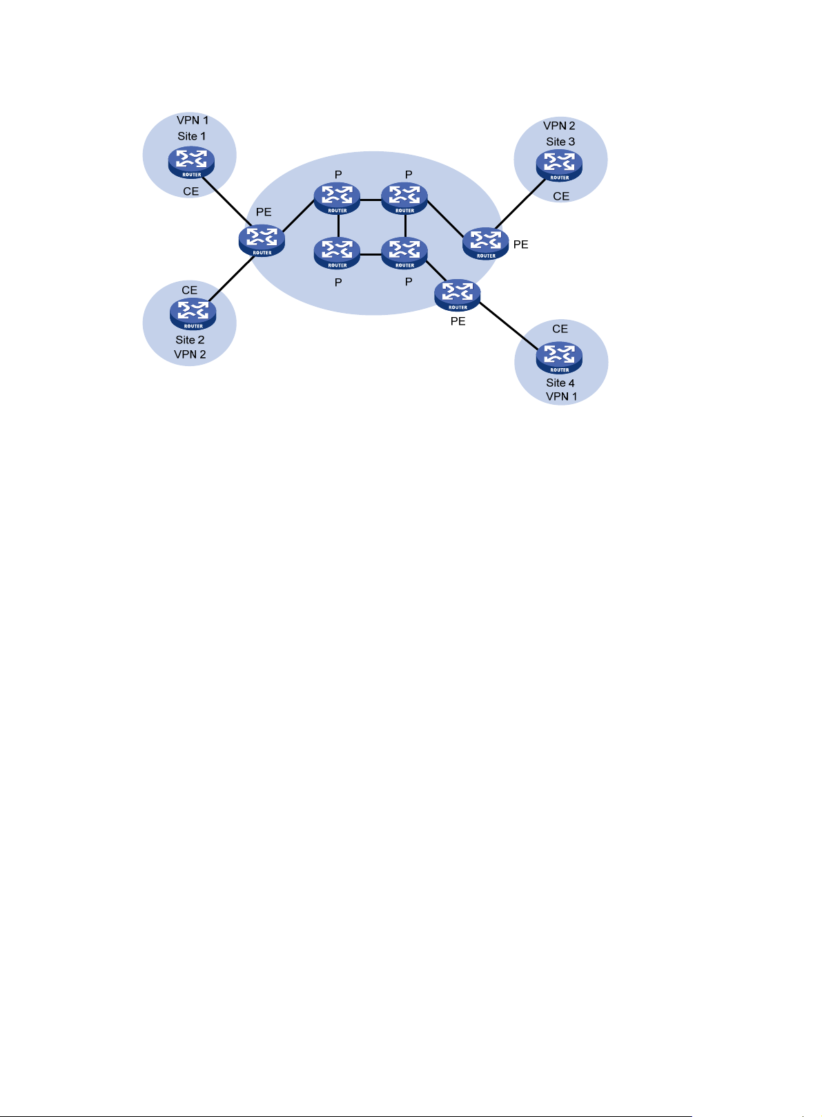
Figure 1 Network diagram for MPLS L3VPN model
CEs and PEs mark the boundary between the service providers and the customers.
After a CE establishes adjacency with a directly connected PE, it advertises its VPN routes to the PE
and learns remote VPN routes from the PE. A CE and a PE use BGP/IGP to exchange routing
information. You can also configure static routes between them.
After a PE learns the VPN routing information for a CE, it uses BGP to exchange VPN routing
information with other PEs. A PE maintains routing information about VPNs that are directly
connected, rather than for all VPN routing information on the provider network.
A P router maintains only routes to PEs and does not deal with VPN routing information.
When VPN traffic travels over the MPLS backbone, the ingress PE functions as the ingress LSR, the
egress PE functions as the egress LSR, and P routers function as the transit LSRs.
MPLS L3VPN concepts
This section describes concepts for MPLS L3VPN.
Site
Sites are often mentioned in the VPN. A site has the following features:
• A site is a group of IP systems with IP connectivity that does not rely on any service-provider
network to implement.
• The classification of a site depends on the topology relationship of the devices, rather than the
geographical positions, although the devices at a site are, in most cases, adjacent to each other
geographically.
• The devices at a site can belong to multiple VPNs.
• A site is connected to a provider network through one or more CEs. A site can contain many
CEs, but a CE can belong to only one site.
Sites connected to the same provider network can be classified into different sets by policies. Only
the sites in the same set can access each other through the provider network. This kind of a set is
called a VPN.
Address space overlapping
Each VPN independently manages the addresses it uses. The assembly of such addresses for a
VPN is called an address space.
2
Page 11
The address spaces of VPNs may overlap. For example, if both VPN 1 and VPN 2 use the addresses
on network segment 10.110.10.0/24, the address space overlaps.
VPN instance
In MPLS VPN, routes of different VPNs are identified by VPN instance.
A PE creates and maintains a separate VPN instance for each VPN at a directly connected site.
Each VPN instance contains the VPN membership and routing rules of the corresponding site. If a
user at a site belongs to multiple VPNs at the same time, the VPN instance of the site contains
information about all the VPNs.
For the independence and security of VPN data, each VPN instance on a PE maintains a routing
table and an LFIB. VPN instance information contains the following items: the LFIB, the IP routing
table, the interfaces bound to the VPN instance, and the administration information for the VPN
instance. The administration information for the VPN instance includes the RD, route filtering policy,
and member interface list.
VPN-IPv4 address
Traditional BGP cannot process overlapping VPN routes. For example, if both VPN 1 and VPN 2 use
the subnet 10.110.10.0/24 and each advertises a route to the subnet, BGP selects only one of them,
resulting in the loss of the other route.
PEs use MP-BGP to advertise VPN routes and use VPN-IPv4 address family to solve the problem
with traditional BGP.
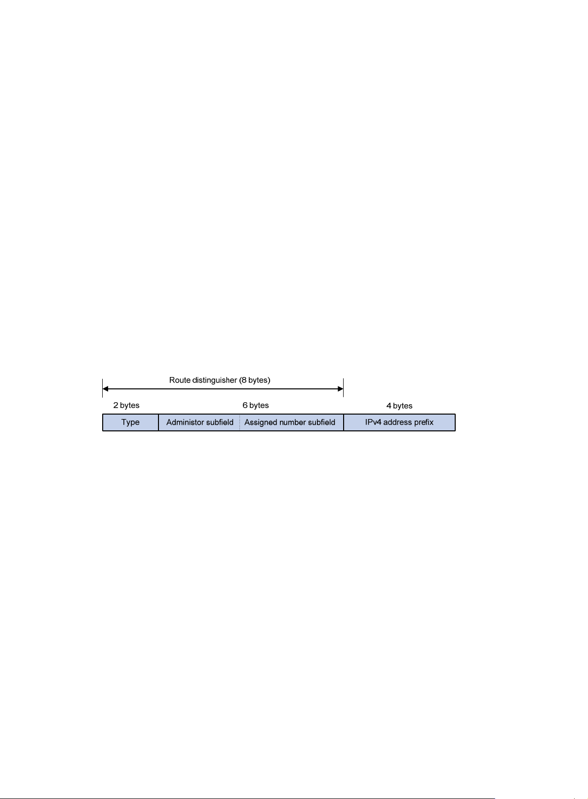
A VPN-IPv4 address has 12 bytes. The first eight bytes represent the RD, followed by a four-byte
IPv4 address prefix.
Figure 2 VPN-IPv4 address structure
When a PE receives an ordinary IPv4 route from a CE, it must advertise the VPN route to the peer
PE. The uniqueness of a VPN route is implemented by adding an RD to the route.
A service provider can independently assign RDs if the assigned RDs are unique. A PE can advertise
different routes to VPNs even if the VPNs are from different service providers and are using the same
IPv4 address space.
Configure a distinct RD for each VPN instance on a PE, so that routes to the same CE use the same
RD. The VPN-IPv4 address with RD 0 is a globally unique IPv4 address.
By prefixing a distinct RD to a specific IPv4 address prefix, you get a globally unique VPN IPv4
address prefix.
An RD can be an AS number plus an arbitrary number or an IP address plus an arbitrary number.
An RD can be in one of the following formats distinguished by the Type field:
• If the value of the Type field is 0, the Administrator subfield occupies two bytes, the Assigned
number subfield occupies four bytes, and the RD format is 16-bit AS number:32-bit
user-defined number. For example, 100:1.
• If the value of the Type field is 1, the Administrator subfield occupies four bytes, the Assigned
number subfield occupies two bytes, and the RD format is 32-bit IPv4 address:16-bit
user-defined number. For example, 172.1.1.1:1.
• If the value of the Type field is 2, the Administrator subfield occupies four bytes, the Assigned
number subfield occupies two bytes, and the RD format is 32-bit AS num ber:16-bit user-defined
number, where the minimum value of the AS number is 65536. For example, 65536:1.
3
Page 12

To guarantee the global uniqueness of an RD, do not set the Administrator subfield to any private AS
number or private IP address.
Route target attributes
MPLS L3VPN uses the BGP extended community attributes called "route target attributes" to control
the advertisement of VPN routing information.
A VPN instance on a PE supports the following types of route target attributes:
• Export target attribute—A local PE sets this type of route target attribute for VPN-IPv4 routes
learned from directly connected sites before advertising them to other PEs.
• Import target attribute—A PE checks the export target attribute of VPN-IPv4 routes
advertised by other PEs. If the export target attribute matches the import target attribute of the
VPN instance, the PE adds the routes to the VPN routing table.
In other words, route target attributes define which sites can receive VPN-IPv4 routes and from
which sites a PE can receive routes.
Similar to RDs, route target attributes can be of the following formats:
• 16-bit AS number:32-bit user-defined number. For example, 100:1.
• 32-bit IPv4 address:16-bit user-defined number. For example, 172.1.1.1:1.
• 32-bit AS number:16-bit user-defined number, where the minimum value of the AS number is
65536. For example, 65536:1.
Multi-VPN-instance CE
BGP/MPLS VPN transmits private network data through MPLS tunnels over the public network.
However, the traditional MPLS L3VPN architecture requires that each VPN instance exclusively use
a CE to connect with a PE, as shown in Figure 1.
For better se
isolate services. To meet these requirements, you can configure a CE for each VPN, which increases
users' device expenses and maintenance costs. Or, you can configure multiple VPNs to use the
same CE and the same routing table, which sacrifices data security.
By using the MCE function, you can have both lower cost and higher security in multi-VPN networks.
You can use MCE to bind each VPN to a VLAN interface on the CE, and create and maintain a
separate routing table for each VPN. This separates the forwarding paths of packets of different
VPNs and, in conjunction with the PE, can correctly advertise the routes of each VPN to the peer PE,
ensuring the normal transmission of VPN packets over the public network.
This section uses Figure 3 to describe
and how an MCE exchanges VPN routes with PEs.
rvices and higher security, a private network is usually divided into multiple VPNs to
how an MCE maintains the routing entries of multiple VPNs
4
Page 13
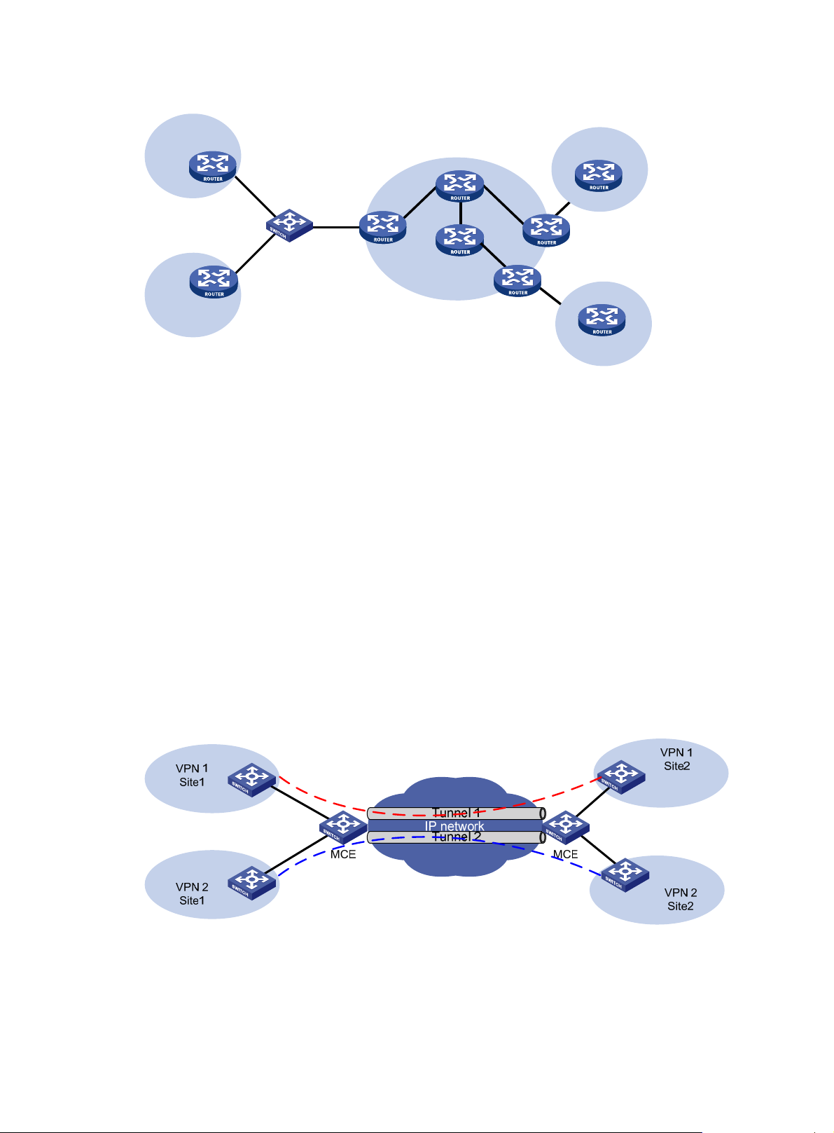
Figure 3 Network diagram for the MCE function
VPN 1
Site 1
VPN 2
Site 2
VLAN-int2
VLAN-int3
MCE
P
PE1
VLAN-int7
VLAN-int8
P
PE
VPN 2
Site 1
CE
PE2
CE
Site 2
VPN 1
On the left-side network, there are two VPN sites, both of which are connected to the MPLS
backbone through the MCE device. VPN 1 and VPN 2 on the left-side network must establish a
tunnel with both VPN 1 and VPN 2 on the right-side network.
The MCE creates one routing table for VPN 1 and one for VPN 2. VLAN-interface 2 is bound to VPN
1, and VLAN-interface 3 is bound to VPN 2. Upon receiving a route, the MCE determines the source
of the route according to the number of the receiving interface, and adds it to the corresponding
routing table.
You must also bind PE 1 interfaces that are connected to the MCE to the VPNs in the same way as
on the MCE. The MCE connects to PE 1 through a trunk link, which permits packets of VLAN 2 and
VLAN 3 to pass through with VLAN tags. Based on the VLAN tag of an incoming packet, PE 1 can
determine its VPN and output tunnel.
Using MCE in tunneling applications
In addition to MPLS L3VPN, you can also use tunneling technologies to implement other types of
VPNs. The MCE function provided by the switch can be applied in VPN applications based on
tunneling.
Figure 4 Network diagram for using MCE in a tunneling application (1)
By establishing multiple tunnels between two MCE devices and binding the tunnel interfaces to VPN
instances, you can make the routing information and data of the VPN instances delivered to the peer
devices through the bound tunnel interfaces. According to the tunnel interfaces receiving the routes,
an MCE device determines the VPN instances that the routes belong to and advertises the routes to
5
Page 14
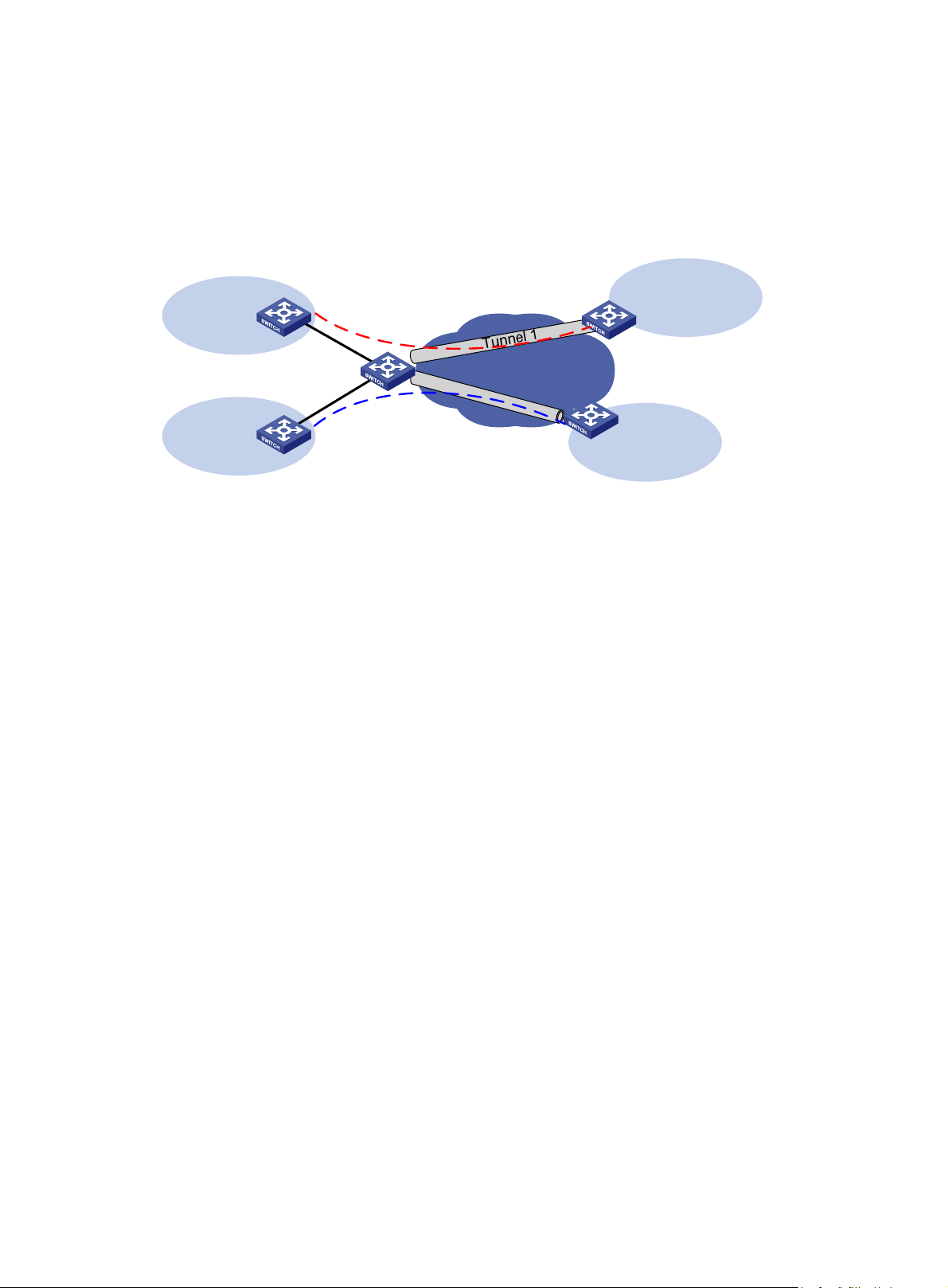
the corresponding sites. As shown in Figure 4, you can bind Tunnel 1 to VPN 1 to make the MCE
devices deliver the routing information and data of VPN 1 through the tunnel.
You can also use an MCE in a tunneling application as shown in Figure 5 to connect multiple remote
CEs th
rough tunnels. In this scenario, the CE devices only need to receive and advertise routes as
usual, while the MCE advertises and receives VPN routing information based on the bindings
between tunnel interfaces and VPNs.
Figure 5 Network diagram for using MCE in a tunneling application (2)
VPN 1
VPN 1
Site1
MCE
IP network
T
u
n
n
e
CE
l
2
Site2
VPN 2
Site1
CE
VPN 2
Site2
MCE devices in a tunneling application can exchange VPN routing information with their peer MCE
devices or CE devices directly, just as MCE devices in an MPLS L3VPN application do with the
corresponding PEs. For more information, see "Route exchange between an MCE and a PE."
GRE tunnel, IPv4 over IPv4 tunnel, and IPv4 over IPv6 tunnel support MCE. For more information
about tunnel types, see Layer 3—IP Services Configuration Guide.
Configuring routing on an MCE
Interface-to-VPN-instance binding enables MCEs and PEs to determine the sources of received
packets and then forward the packets according to the routing information concerning the
corresponding VPNs. MCE routing configuration includes:
• MCE-VPN site routing configuration
• MCE-PE routing configuration
Route exchange between an MCE and a VPN site
An MCE can adopt the following routing protocols to exchange VPN routes with a site:
• Static route
• RIP
• OSPF
• IS-IS
• IBGP
• EBGP
This section briefly introduces the cooperation of routing protocols and MCE. For information about
the routing protocols, see Layer 3—IP Routing Configuration Guide.
Static routes
An MCE can communicate with a site through static routes. As static routes configured for traditional
CEs take effect globally, address overlapping between multiple VPNs remains a problem until the
6
Page 15

RIP
OSPF
emergence of MCE. MCE allows static-route-to-VPN-instance binding, which isolates the static
routes of different VPNs.
The switch can bind RIP processes to VPN instances. With these bindings on the MCE, private
network routes of different VPNs can be exchanged between MCE and sites through different RIP
processes, isolating and securing VPN routes.
The switch can bind OSPF processes to VPN instances and isolate the routes of different VPNs.
For an OSPF process bound to a VPN instance, the router ID of the public network configured in
system view is invalid. You must specify the router ID when creating an OSPF process.
An OSPF process can be bound to only one VPN instance. A VPN instance can use multiple OSPF
processes for private network route transmission. To make sure routes can be advertised correctly,
configure the same domain ID for all OSPF processes bound to the same VPN instance.
Routes redistributed from OSPF to BGP on the MCE have their OSPF attributes removed. To enable
BGP to distinguish routes redistributed from different OSPF domains, you must enable the
redistributed routes to carry the OSPF domain ID by configuring the domain-id command in OSPF
view. The domain ID is added to BGP VPN routes as an extended community attribute.
In cases where a VPN has multiple MCE devices attached to it and when an MCE device advertises
the routes learned from BGP within the VPN, the routes may be learned by other MCE devices,
generating route loops. To prevent route loops, configure route tags for different VPN instances on
each MCE. Hewlett Packard Enterprise recommends that you assign the same route tag to the same
VPN on all MCEs.
IS-IS
Similar to those in OSPF, IS-IS processes can be bound to VPN instances for private network routes
to be exchanged between MCE and sites. An IS-IS process can be bound to only one VPN instance.
IBGP
To use IBGP to exchange private routes between an MCE and a site, configure IBGP peers for VPN
instances on the MCE and redistribute IGP routing information from corresponding VPNs. If the MCE
is connected with multiple sites in the same VPN, you can configure the MCE as a route reflector (RR)
and configure the egress routers of the sites as clients, making the MCE reflect routing information
between the sites. This eliminates the necessity for BGP connections between sites, reducing the
number of BGP connections and simplifying network configuration.
EBGP
To use EBGP for exchanging routing information between an MCE and VPN sites, you must
configure a BGP peer for each VPN instance on the MCE, and redistribute the IGP routes of each
VPN instance on the VPN sites. You also can configure filtering policies to filter the received routes
and the routes to be advertised.
Route exchange between an MCE and a PE
Routing information entries are bound to specific VPN instances on an MCE device, and packets of
each VPN instance are forwarded between MCE and PE according to interface. As a result, VPN
routing information can be transmitted by performing relatively simple configurations between MCE
and PE, such as importing the VPN routing entries on MCE devices to the routing table of the routing
protocol running between MCE and PEs.
The following routing protocols can be used between MCE and PE devices for routing formation
exchange:
• Static route
• RIP
7
Page 16

• OSPF
• IS-IS
• IBGP
• EBGP
For information about routing protocol configuration and route import, see Layer 3—IP Routing
Configuration Guide.
Configuring VPN instances
You must configure VPN instances in all MCE networking schemes.
VPN instances isolate not only VPN routes from public network routes, but also routes of a VPN from
those of another VPN. This feature allows VPN instances to be used in networking scenarios
besides MCE.
Creating a VPN instance
A VPN instance is associated with a site. It is a collection of the VPN membership and routing rules of
its associated site. A VPN instance does not necessarily correspond to one VPN.
A VPN instance takes effect only after you configure an RD for it. Before configuring an RD for a VPN
instance, you can configure no other parameters for the instance but a description.
You can configure a description for a VPN instance to record its related information, such as its
relationship with a certain VPN.
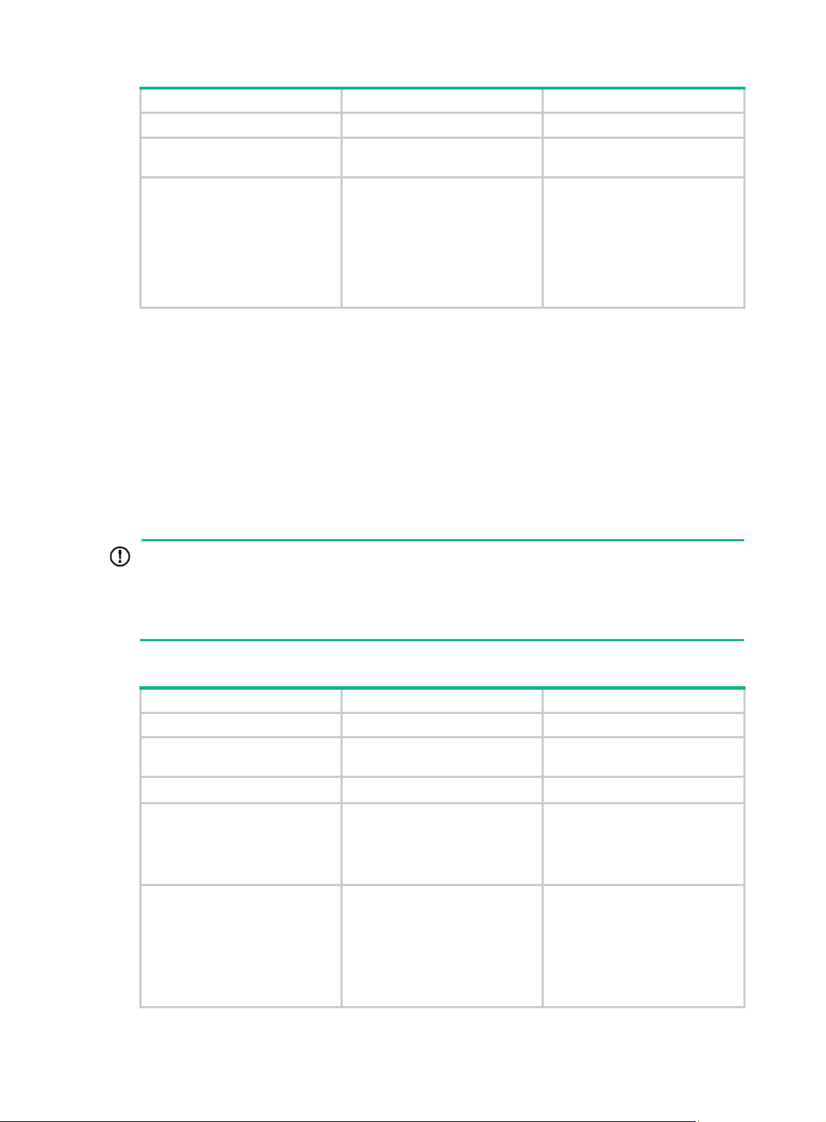
To create and configure a VPN instance:
Step Command Remarks
1. Enter system view.
2. Create a VPN instance and
enter VPN instance view.
3. Configure an RD for the VPN
instance.
4. Configure a description for
the VPN instance.
system-view
ip vpn-instance
vpn-instance-name
route-distinguisher
route-distinguisher
description
text
N/A
N/A
For easy management, set the
same RD for the same VPN
instance on the MCE and the PE.
Optional.
Associating a VPN instance with an interface
After you create and configure a VPN instance, you must associate the VPN instance with the
interfaces connected to the VPN sites.
In an MPLS L3VPN application, you must also associate the VPN instances with the interfaces
connected to the PE.
In a tunneling application, you must associate the VPN instances with the tunnel interfaces
connecting the peer MCE device or CE device.
You can add a management Ethernet interface on the switch to a VPN, so the IP address of the
interface only participates in the route calculation of the specified VPN.
To associate a VPN instance with an interface:
8
Page 17
Step Command Remarks
5. Enter system view.
system-view
N/A
6. Enter interface view.
7. Associate the interface with
a VPN instance.
interface
interface-number
ip binding vpn-instance
vpn-instance-name
interface-type
N/A
By default, no VPN instance is
associated with any interface.
Associating the interface with a
VPN instance clears the IP
address of the interface.
Therefore, you must reconfigure
the IP address of the interface
after executing this command.
Configuring route attributes of a VPN instance
The control process of VPN route advertisement is as follows:
• When a VPN route learned from a site is redistributed into BGP, BGP associates the route with
a route target extended community attribute list, which is usually the export target attribute of
the VPN instance associated with the site.
• The VPN instance determines which routes it can accept and redistribute according to the
import-extcommunity in the route target.
• The VPN instance determines how to change the route targets attributes for routes to be
advertised according to the export-extcommunity in the route target.
IMPORTANT:
• The route target attribute can be advertised to the PE along with the routing information only
when BGP runs between the MCE and PE. In other cases, this attribute does not take effect.
• Before associating a routing policy with a VPN instance, you must first create the routing policy.
Otherwise, the default routing policy is used.
To configure route related attributes of a VPN instance:
Step Command Remarks
1. Enter system view.
2. Enter VPN instance view.
3. Enter IPv4 VPN view.
4. Associate the current VPN
instance with one or more
route targets.
5. Configure the maximum
number of routes for the
VPN instance.
system-view
ip vpn-instance
vpn-instance-name
ipv4-family
vpn-target
both
[
import-extcommunity
routing-table limit
{ warn-threshold |
export-extcommunity
|
vpn-target&<1-8>
number
simply-alert
N/A
N/A
Optional.
A single
can configure up to eight route
|
targets. You can configure up to
]
64 route targets for a VPN
instance.
Optional.
Not configured by default.
Setting the maximum number of
routes for a VPN instance to
}
support is for preventing too many
routes from being redistributed
into the PE.
vpn-target
command
9
Page 18

Step Command Remarks
6. Apply an import routing
policy to the current VPN
instance.
7. Apply an export routing
policy to the current VPN
instance.
NOTE:
import route-policy
export route-policy
route-policy
route-policy
You can configure route related attributes for IPv4 VPNs in both VPN instance view and IPv4 VPN
view. Those configured in IPv4 VPN view take precedence.
Configuring routing on an MCE
MCE implements service isolation by using route isolation. MCE routing configuration includes:
• Routing configuration between an MCE and a VPN site
• Routing configuration between an MCE and a PE
Optional.
By default, all routes permitted by
the import target attribute can be
redistributed into the VPN
instance.
Optional.
By default, all VPN instance
routes permitted by the export
target attribute can be
redistributed.
On the PE in an MCE network environment, disable routing loop detection to avoid route loss during
route calculation and disable route redistribution between routing protocols to save system
resources.
Before you configure routing on an MCE, complete the following tasks:
• On the MCE, configure VPN instances, and bind the VPN instances to the interfaces that are
connected to the VPN sites and to the PE.
• Configure the link layer and network layer protocols on related interfaces to ensure IP
connectivity.
Configuring routing between an MCE and a VPN site
This section shows how to configure static routing, RIP, OSPF, IS-IS, EBGP, or IBGP between an
MCE and a VPN site.
Configuring static routing between an MCE and a VPN site
An MCE can reach a VPN site through a static route. Static routing on a traditional CE is globally
effective and thus does not support address overlapping among VPNs. An MCE supports binding a
static route to a VPN instance, so that the static routes of different VPN instances can be isolated
from each other.
To configure static routing between an MCE and a VPN site:
Step Command Remarks
1. Enter system view.
system-view
N/A
10
Page 19

Step Command Remarks
• ip route-static dest-address { mask |
mask-length } { gateway-address |
interface-type interface-number
[ gateway-address ] | vpn-instance
2. Configure a static
route for a VPN
instance.
d-vpn-instance-name gateway-address }
[ preference preference-value ] [ tag
tag-value ] [ description description-text ]
• ip route-static vpn-instance
s-vpn-instance-name&<1-6> dest-address
{ mask | mask-length } { gateway-address
[ public ] | interface-type interface-number
[ gateway-address ] | vpn-instance
d-vpn-instance-name gateway-address }
[ preference preference-value ] [ tag
tag-value ] [ description description-text ]
Use either command.
Perform this
configuration on the
MCE. On a VPN site,
configure a normal static
route.
3. Configure the default
precedence for static
routes.
ip route-static default-preference
default-preference-value
Configuring RIP between an MCE and a VPN site
A RIP process belongs to the public network or a single VPN instance. If you create a RIP process
without binding it to a VPN instance, the process belongs to the public network. By configuring RIP
process-to-VPN instance bindings on an IPv6 MCE, you allow routes of different VPNs to be
exchanged between the MCE and the sites through different RIP processes, ensuring the separation
and security of VPN routes.
For more information about RIP, see Layer 3—IP Routing Configuration Guide.
To configure RIP between MCE and VPN site:
Step Command Remarks
1. Enter system view.
2. Create a RIP process for a
VPN instance and enter RIP
view.
3. Enable RIP on the interface
attached to the specified
network.
4. Redistribute remote site
routes advertised by the PE.
5. Configure the default cost
value for the redistributed
routes.
system-view
rip
[ process-id ]
vpn-instance-name
network
import-route
[
process-id
cost
route-policy-name |
default cost
network-address
] [
| route-policy
value
vpn-instance
tag
tag ] *
protocol
allow-ibgp
] [
cost
Optional.
The default setting is 60.
N/A
Perform this configuration on the
MCE. On a VPN site, create a
normal RIP process.
By default, RIP is disabled on an
interface.
By default, no route is
redistributed into RIP.
Optional.
0 by default.
Configuring OSPF between an MCE and a VPN site
An OSPF process belongs to the public network or a single VPN instance. If you create an OSPF
process without binding it to a VPN instance, the process belongs to the public network.
By configuring OSPF process-to-VPN instance bindings on a MCE, you allow routes of different
VPNs to be exchanged between the MCE and the sites through different OSPF processes, ensuring
the separation and security of VPN routes.
For more information about OSPF, see Layer 3—IP Routing Configuration Guide.
11
Page 20

To configure OSPF between an MCE and a VPN site:
Step Command Remarks
1. Enter system view.
2. Create an OSPF process for
a VPN instance and enter
OSPF view.
3. Configure the OSPF domain
ID.
system-view
ospf
[ process-id |
router-id |
vpn-instance-name ] *
domain-id
secondary
[
vpn-instance
domain-id
]
router-id
N/A
Perform this configuration on the
MCE. On a VPN site, create a
normal OSPF process.
An OSPF process can belong to
only one VPN instance, but one
VPN instance can use multiple
OSPF processes to advertise the
VPN routes.
Optional.
By default, the domain ID is 0.
Perform this configuration on the
MCE. On a VPN site, perform the
common OSPF configuration.
4. Redistribute remote site
routes advertised by the PE.
5. Create an OSPF area and
enter OSPF area view.
6. Enable OSPF on the
interface attached to the
specified network in the
area.
import-route
[ process-id |
cost |
route-policy
*
area
area-id
network
wildcard-mask
protocol
allow-ibgp
type
type |
route-policy-name ]
ip-address
An OSPF process that is bound with a VPN instance does not use the public network router ID
configured in system view. Therefore, you must configure a router ID when starting the OSPF
process. All OSPF processes for the same VPN must be configured with the same OSPF domain ID
to ensure correct route advertisement.
Configuring IS-IS between an MCE and a VPN site
An IS-IS process belongs to the public network or a single VPN instance. If you create an IS-IS
process without binding it to a VPN instance, the process belongs to the public network.
By configuring IS-IS process-to-VPN instance bindings on a MCE, you allow routes of different VPNs
to be exchanged between the MCE and the sites through different IS-IS processes, ensuring the
separation and security of VPN routes.
For more information about IS-IS, see Layer 3—IP Routing Configuration Guide.
tag
tag |
] [
cost
By default, no route of any other
routing protocol is redistributed
into OSPF.
By default, no OSPF area is
created.
By default, an interface neither
belongs to any area nor runs
OSPF.
To configure IS-IS between an MCE and a VPN site:
Step Command Remarks
1. Enter system view.
2. Create an IS-IS process for a
VPN instance and enter
IS-IS view.
3. Configure a network entity
title.
system-view
isis
[ process-id ]
vpn-instance-name
network-entity
vpn-instance
net
12
N/A
Perform this configuration on the
MCE. On a VPN site, configure a
normal IS-IS process.
Not configured by default.
Page 21

Step Command Remarks
Optional.
By default, IS-IS does not
redistribute routes of any other
] |
routing protocol.
If you do not specify the route
} |
level in the command, the
command redistributes routes to
the level-2 routing table by
default.
N/A
4. Redistribute remote site
routes advertised by the PE.
5. Return to system view.
import-route
ospf
[ process-id ] |
[ process-id ] |
direct
cost-type
[
route-policy
tag
quit
|
level-1
tag ] *
static
external
{
level-1-2
|
isis
{
[ process-id ] |
rip
bgp
allow-ibgp
[
cost
} [
cost |
internal
|
level-2
|
route-policy-name |
] |
6. Enter interface view.
7. Enable the IS-IS process on
the interface.
interface
interface-number
isis enable
interface-type
[ process-id ]
Configuring EBGP between an MCE and a VPN site
To use EBGP for exchanging routing information between an MCE and VPN sites, configure a BGP
peer for each VPN instance on the MCE, and redistribute the IGP routes of each VPN instance on
the VPN sites.
If EBGP is used for route exchange, you also can configure filtering policies to filter the received
routes and the routes to be advertised.
1. Configure the MCE:
Step Command Remarks
1. Enter system view.
2. Enter BGP view.
3. Enter BGP-VPN instance
view.
4. Configure an EBGP peer.
5. Allow the local AS number to
appear in the AS_PATH
attribute of a received route,
and set the maximum
number of times that such
case is allowed to appear.
system-view
bgp
as-number N/A
ipv4-family vpn-instance
vpn-instance-name
peer
{ group-name | ip-address }
as-number
peer
allow-as-loop
as-number
{ group-name | ip-address }
[ number ]
N/A
Disabled by default.
N/A
N/A
N/A
Optional.
6. Redistribute remote site
routes advertised by the PE.
7. Configure a filtering policy to
filter the routes to be
advertised.
8. Configure a filtering policy to
filter the received routes.
import-route
[ process-id |
med
[
route-policy-name ] *
filter-policy
ip-prefix
direct | isis
[
process-id |
static
filter-policy
ip-prefix
protocol
all-processes
med-value
ip-prefix-name }
]
| route-policy
{ acl-number |
process-id |
rip
process-id |
{ acl-number |
ip-prefix-name }
13
]
export
ospf
import
By default, no route redistribution
is configured.
Optional.
By default, BGP does not filter the
routes to be advertised.
Optional.
By default, BGP does not filter the
received routes.
Page 22

BGP checks routing loops by examining AS numbers. If EBGP is used, the MCE advertises routing
information carrying the local AS number to the site and then receives routing updates from the site.
The routing updates carry the AS number of the MCE, so the MCE discards the updates to avoid
routing loops. To enable the MCE to receive these routes, configure the MCE to allow routing loops.
Routes redistributed from OSPF to BGP on the MCE have their OSPF attributes removed. To enable
BGP to distinguish routes redistributed from different OSPF domains, you must enable the
redistributed routes to carry the OSPF domain ID by configuring the domain-id command in OSPF
view. The domain ID is added to BGP VPN routes as an extended community attribute.
BGP runs in a BGP VPN instance in the same way as it runs in a normal network. For more
information about BGP, see Layer 3—IP Routing Configuration Guide.
2. Configure a VPN site:
Step Command Remarks
1. Enter system view.
system-view
N/A
2. Enter BGP view.
3. Configure the MCE as the
EBGP peer.
4. Redistribute the IGP routes
of the VPN.
bgp
as-number N/A
peer
{ group-name | ip-address }
as-number
import-route
[ process-id ] [
route-policy
*
as-number
protocol
med
route-policy-name ]
Configuring IBGP between an MCE and a VPN site
If IBGP is used for exchanging routing information between an MCE and VPN sites, configure a BGP
peer for each VPN instance, and redistribute the IGP routes of each VPN instance on the VPN sites.
1. Configure the MCE:
Step Command Remarks
1. Enter system view.
2. Enter BGP view.
3. Enter BGP-VPN instance
view.
4. Configure an IBGP peer.
system-view
bgp
as-number N/A
ipv4-family vpn-instance
vpn-instance-name
peer
{ group-name | ip-address }
as-number
as-number
med-value |
N/A
Optional.
A VPN site must advertise the
VPN network addresses it can
reach to the connected MCE.
N/A
N/A
N/A
5. Configure the system to be
the RR and specify the peer
as the client of the RR.
6. Redistribute remote site
routes advertised by the PE.
7. Configure a filtering policy to
filter the routes to be
advertised.
8. Configure a filtering policy to
filter the received routes.
peer
{ group-name | ip-address }
reflect-client
import-route
[ process-id |
med
[
route-policy-name ] *
filter-policy
ip-prefix
direct | isis
[
process-id |
static
filter-policy
ip-prefix
protocol
all-processes
med-value
ip-prefix-name }
]
| route-policy
{ acl-number |
process-id |
rip
process-id |
{ acl-number |
ip-prefix-name }
14
]
export
ospf
import
Optional.
By default, no RR or RR client is
configured.
By default, no route redistribution
is configured.
Optional.
By default, BGP does not filter the
routes to be advertised.
Optional.
By default, BGP does not filter the
received routes.
Page 23

t
NOTE:
After you configure a VPN site as an IBGP peer of the MCE, the MCE does not advertise the BGP
routes learned from the VPN site to other IBGP peers, including VPNv4 peers. An MCE advertises
routes learned from a VPN site to other IBGP peers only when you configure the VPN site as a clien
of the RR (the MCE).
2. Configure a VPN site:
Step Command Remarks
1. Enter system view.
system-view
N/A
2. Enter BGP view.
3. Configure the MCE as the
IBGP peer.
4. Redistribute the IGP routes
of the VPN.
bgp
as-number N/A
peer
{ group-name | ip-address }
as-number
import-route
[ process-id ] [
route-policy
*
as-number
protocol
med
med-value |
route-policy-name ]
N/A
Optional.
A VPN site must advertise the
VPN network addresses it can
reach to the connected MCE.
Configuring routing between an MCE and a PE
MCE-PE routing configuration includes these tasks:
• Bind the MCE-PE interfaces to VPN instances
• Perform route configurations
• Redistribute VPN routes into the routing protocol running between the MCE and the PE.
Configuring static routing between an MCE and a PE
Step Command Remarks
1. Enter system view.
2. Configure a static
route for a VPN
instance.
3. Configure the default
precedence for static
routes.
system-view
• ip route-static dest-address { mask |
mask-length } { gateway-address |
interface-type interface-number
[ gateway-address ] | vpn-instance
d-vpn-instance-name gateway-address }
[ preference preference-value ] [ tag
tag-value ] [ description description-text ]
• ip route-static vpn-instance
s-vpn-instance-name&<1-6> dest-address
{ mask | mask-length } { gateway-address
[ public ] | interface-type interface-number
[ gateway-address ] | vpn-instance
d-vpn-instance-name gateway-address }
[ preference preference-value ] [ tag
tag-value ] [ description description-text ]
ip route-static default-preference
default-preference-value
N/A
Use either command.
Optional.
60 by default.
Configuring RIP between an MCE and a PE
15
Page 24

Step Command Remarks
1. Enter system view.
2. Create a RIP process for a
VPN instance and enter RIP
view.
3. Enable RIP on the interface
attached to the specified
network.
system-view
rip
[ process-id ]
vpn-instance
vpn-instance-name
network
network-address
N/A
N/A
By default, RIP is disabled
on an interface.
import-route
allow-ibgp
4. Redistribute the VPN routes.
[
route-policy
tag ] *
5. Configure the default cost
value for the redistributed
default cost
routes.
Configuring OSPF between an MCE and a PE
Step Command Remarks
1. Enter system view.
2. Create an OSPF
process for a VPN
instance and enter
OSPF view.
3. Disable routing loop
detection.
4. Configure the OSPF
domain ID.
system-view
ospf
[ process-id |
vpn-instance
vpn-instance-capability simple
domain-id
domain-id [
cost
[
process-id
cost
|
protocol
] [
route-policy-name |
value
router-id
router-id |
vpn-instance-name ] *
secondary
]
]
By default, no route of any
tag
other routing protocol is
redistributed into RIP.
Optional.
0 by default.
N/A
N/A
Disabled by default.
Disable routing loop detection
for a VPN OSPF process on
the MCE. Otherwise, the MCE
cannot receive OSPF routes
from the PE.
Optional.
By default, the domain ID is 0.
5. Redistribute the VPN
routes.
6. Configure a filtering
policy to filter the
advertised routes.
7. Configure the default
parameters for
redistributed routes
(cost, route number,
tag, and type).
8. Create an OSPF area
and enter OSPF area
view.
9. Enable OSPF on the
interface attached to
the specified network in
the area.
import-route
allow-ibgp
route-policy
tag |
filter-policy
protocol [ process-id |
] [
{ acl-number |
ip-prefix-name }
[ process-id ] ]
default { cost
type
area
area-id
network
type } *
ip-address wildcard-mask
cost
cost |
type
route-policy-name ] *
ip-prefix
export [
cost |
limit
protocol
limit |
16
type |
tag
tag
tag |
By default, no route of any
other routing protocol is
redistributed into OSPF.
Optional.
By default, advertised routes
are not filtered.
Optional.
The default cost is 1, the
default maximum number of
routes redistributed per time is
1000, the default tag is 1, and
default type of redistributed
routes is Type-2.
By default, no OSPF area is
created.
By default, an interface neither
belongs to any area nor runs
OSPF.
Page 25

Configuring IS-IS between an MCE and a PE
Step Command Remarks
1. Enter system view.
2. Create an IS-IS
process for a VPN
instance and enter
IS-IS view.
3. Configure a network
entity title.
4. Redistribute the VPN
routes.
system-view
isis
[ process-id ]
vpn-instance-name
network-entity
import-route
[ process-id ] |
allow-ibgp
[
cost |
level-1
[
route-policy
] |
cost-type
level-1-2
|
route-policy-name |
tag ] *
vpn-instance
net
isis
{
[ process-id ] |
rip
[ process-id ] |
direct
|
external
{
level-2
|
static
|
] |
ospf
bgp
cost
} [
internal
tag
N/A
N/A
By default, no network entity title
is configured.
Optional.
By default, IS-IS does not
redistribute routes of any other
routing protocol.
} |
If you do not specify the route
level in the command, the
command redistributes routes to
the level-2 routing table by
default.
5. Configure a filtering
policy to filter the
advertised routes.
6. Return to system view.
7. Enter interface view.
filter-policy
ip-prefix-name |
route-policy-name }
process-id |
process-id |
quit
interface
interface-number
{ acl-number |
ospf
bgp
interface-type
8. Enable the IS-IS
process on the
isis enable
[ process-id ]
interface.
Configuring EBGP between an MCE and a PE
Step Command Remarks
1. Enter system view.
2. Enter BGP view.
3. Enter BGP-VPN
instance view.
4. Configure the PE as the
EBGP peer.
system-view
bgp
as-number N/A
ipv4-family vpn-instance
vpn-instance-name
peer
{ group-name | ip-address }
as-number
as-number
ip-prefix
route-policy
export
[
process-id |
direct
|
static
|
isis
rip
Optional.
By default, IS-IS does not filter
advertised routes.
]
N/A
N/A
Disabled by default.
N/A
N/A
N/A
5. Redistribute the VPN
routes of the VPN site.
6. Configure a filtering
policy to filter the routes
to be advertised.
7. Configure a filtering
policy to filter the
received routes.
import-route
all-processes
route-policy
filter-policy
protocol [ process-id |
] [
route-policy-name ] *
{ acl-number |
ip-prefix-name }
process-id |
process-id |
filter-policy
ospf
static
{ acl-number |
ip-prefix-name }
med
med-value
export
process-id |
]
import
17
ip-prefix
direct | isis
[
rip
ip-prefix
|
By default, no route
redistribution is configured.
Optional.
By default, BGP does not
filter the routes to be
advertised.
Optional.
By default, BGP does not
filter the received routes.
Page 26

NOTE:
BGP runs within a VPN in the same way as it runs within a public network. For more information
about BGP, see Layer 3—IP Routing Configuration Guide.
Configuring IBGP between an MCE and a PE
Step Command Remarks
1. Enter system view.
system-view
N/A
2. Enter BGP view.
3. Enter BGP-VPN
instance view.
4. Configure the PE as the
IBGP peer.
5. Redistribute the VPN
routes of the VPN site.
6. Configure the egress
router of the site as a
client of the route
reflector.
7. Enable route reflection
between clients.
8. Specify a cluster ID for
the route reflector.
bgp
as-number N/A
ipv4-family vpn-instance
vpn-instance-name
peer
{ group-name | ip-address }
as-number
import-route
all-processes
route-policy
peer
reflect-client
reflect between-clients
reflector cluster-id
as-number
protocol [ process-id |
med
] [
route-policy-name ] *
{ group-name | ip-address }
med-value
cluster-id
|
N/A
N/A
By default, no route
redistribution is configured.
Optional.
By default, no route reflector
or client is configured.
Optional.
Enabled by default.
If the clients are fully meshed,
you do not need to enable
route reflection.
Optional.
By default, each RR in a
cluster uses its own router ID
as the cluster ID.
If more than one RR exists in
a cluster, use this command
to configure the same cluster
ID for all RRs in the cluster to
avoid routing loops.
9. Configure a filtering
policy to filter the routes
to be advertised.
10. Configure a filtering
policy to filter the
received routes.
filter-policy
ip-prefix-name }
process-id |
process-id |
filter-policy
ip-prefix-name }
{ acl-number |
export
ospf
process-id |
static
]
{ acl-number |
import
Resetting BGP connections
If the BGP configuration changes, you can refresh or reset BGP connections to make new
configurations take effect. Refreshing BGP connections refers to updating BGP routing information
without breaking BGP neighbor relationships. A refreshing operation requires that BGP peers have
route refreshment capability (supporting Route-Refresh messages).
To refresh or reset BGP connections, execute the following commands in user view:
18
ip-prefix
direct | isis
[
rip
ip-prefix
Optional.
By default, BGP does not
filter the routes to be
advertised.
Optional.
By default, BGP does not
filter the received routes.
Page 27

Task Command
Refresh the BGP connections in a
specific VPN instance.
refresh bgp vpn-instance
external | group
group-name } {
vpn-instance-name { ip-address |
export
import
|
}
all
|
Reset BGP connections of a VPN
instance.
reset bgp vpn-instance
all
ip-address |
external
|
vpn-instance-name { as-number |
group
|
Displaying and maintaining MCE
Task Command Remarks
Display information about the
routing table associated with a
VPN instance.
Display information about a
specific VPN instance or all VPN
instances.
Display information about the FIB
of a VPN instance.
Display information about the FIB
of a VPN instance that matches
the specified destination IP
address.
display ip routing-table vpn-instance
vpn-instance-name [
exclude | include
|
display ip vpn-instance
instance-name
[
begin
{
regular-expression ]
display fib vpn-instance
vpn-instance-name [
ip-prefix
exclude
display fib vpn-instance
vpn-instance-name ip-address [ mask |
mask-length ] [
include
exclude
|
ip-prefix-name ] [
include
|
} regular-expression ]
verbose
} regular-expression ]
vpn-instance-name ] [
include
|
acl
} regular-expression ]
|
begin
{
] [ | {
}
acl-number |
|
begin
{
exclude |
|
group-name }
begin
|
Available in any view.
|
Available in any view.
Available in any view.
Available in any view.
Display information about a
specific peer group or all BGP
VPNv4 peer groups.
Display information about BGP
VPNv4 routes injected into a
specific VPN instance or all VPN
instances.
Display BGP VPNv4 AS path
information.
Display information about BGP
VPNv4 peers.
display bgp vpnv4 vpn-instance
vpn-instance-name
begin
[ | {
regular-expression ]
display bgp vpnv4 vpn-instance
vpn-instance-name
exclude
display bgp vpnv4 vpn-instance
vpn-instance-name
[ as-regular-expression | {
exclude
display bgp vpnv4 vpn-instance
vpn-instance-name
log-info
verbose
exclude
exclude
|
include
|
include
|
| ip-address {
verbose
} |
include
|
group [
|
network [ |
} regular-expression ]
paths
} regular-expression } ]
peer
} regular-expression ]
group-name ]
include
] [ | {
}
|
begin
{
[ group-name
log-info
begin
{
|
|
begin
|
Available in any view.
|
Available in any view.
Available in any view.
Available in any view.
19
Page 28

Task Command Remarks
Display the BGP VPNv4 routing
information for a specific VPN
instance.
Clear the route flap dampening
information for a VPN instance.
Clear route flap history
information about a BGP peer of a
VPN instance.
display bgp vpnv4 vpn-instance
vpn-instance-name
[ network-address [ { mask | mask-length }
longer-prefixes
[
as-path-acl-number |
[
aa:nn ]&<1-13> [
no-export
whole-match
[
{ basic-community-list-number
whole-match
[
adv-community-list-number }&<1-16> |
dampened | dampening parameter
different-origin-as | flap-info
[ network-address [ { mask | mask-length }
longer-match
[
as-path-acl-number ]
advertised-routes | received-routes
{
statistic
regular-expression | [
regular-expression
as-regular-expression ]
reset bgp vpn-instance
vpn-instance-name
[ network-address [ mask | mask-length ]
reset bgp vpn-instance
vpn-instance-name ip-address
reset bgp vpn-instance
vpn-instance-name
[ mask | mask-length ] |
as-path-acl-number |
as-path-regexp ]
no-export-subconfed
|
] [ | {
routing-table
as-path-acl
] ] |
cidr
no-advertise
community-list
] |
] |
as-path-acl
] ] |
| peer
begin
exclude
|
flap-info
dampening
flap-info
regexp
as-path-acl
|
community
|
] *
|
ip-address
include
|
]
flap-info
[ ip-address
able in any view.
Avail
} |
}
Available in user view.
Available in user view.
For commands to display information about a routing table, see Layer 3—IP Routing Command
Reference.
Configuration examples
Using OSPF to advertise VPN routes to the PE
Network requirements
As shown in Figure 6, the MCE is connected to VPN 1 through VLAN-interface 10 and to VPN 2
through VLAN-interface 20. RIP runs in VPN 2.
Configure the MCE to separate routes from different VPNs and advertise the VPN routes to PE 1
through OSPF.
20
Page 29
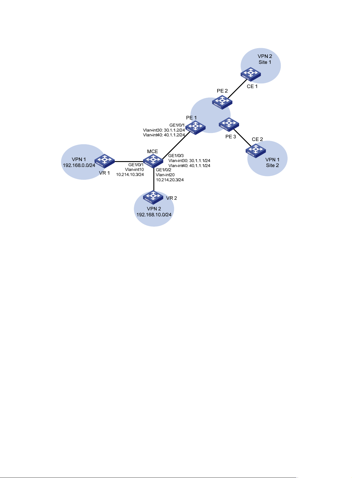
Figure 6 Network diagram
Configuration procedure
Assume that the system name of the MCE device is MCE, the system names of the edge devices of
VPN 1 and VPN 2 are VR1 and VR2, respectively, and the system name of PE 1 is PE1.
1. Configure the VPN instances on the MCE and PE 1:
# On the MCE, configure VPN instances vpn1 and vpn2, and specify an RD and route targets
for each VPN instance.
<MCE> system-view
[MCE] ip vpn-instance vpn1
[MCE-vpn-instance-vpn1] route-distinguisher 10:1
[MCE-vpn-instance-vpn1] vpn-target 10:1
[MCE-vpn-instance-vpn1] quit
[MCE] ip vpn-instance vpn2
[MCE-vpn-instance-vpn2] route-distinguisher 20:1
[MCE-vpn-instance-vpn2] vpn-target 20:1
[MCE-vpn-instance-vpn2] quit
# Create VLAN 10, add port GigabitEthernet 1/0/1 to VLAN 10, and create VLAN-interface 10.
[MCE] vlan 10
[MCE-vlan10] port gigabitethernet 1/0/1
[MCE-vlan10] quit
[MCE] interface vlan-interface 10
# Bind VLAN-interface 10 to VPN instance vpn1, and configure an IP address for
VLAN-interface 10.
[MCE-Vlan-interface10] ip binding vpn-instance vpn1
[MCE-Vlan-interface10] ip address 10.214.10.3 24
21
Page 30

# Configure VLAN 20, add port GigabitEthernet 1/0/2 to VLAN 20, bind VLAN-interface 20 to
VPN instance vpn2, and specify an IP address for VLAN-interface 20.
[MCE-Vlan-interface10] quit
[MCE] vlan 20
[MCE-vlan20] port gigabitethernet 1/0/2
[MCE-vlan20] quit
[MCE] interface vlan-interface 20
[MCE-Vlan-interface20] ip binding vpn-instance vpn2
[MCE-Vlan-interface20] ip address 10.214.20.3 24
[MCE-Vlan-interface20] quit
# On PE 1, configure VPN instances vpn1 and vpn2, and specify an RD and route targets for
each VPN instance.
<PE1> system-view
[PE1] ip vpn-instance vpn1
[PE1-vpn-instance-vpn1] route-distinguisher 30:1
[PE1-vpn-instance-vpn1] vpn-target 10:1
[PE1-vpn-instance-vpn1] quit
[PE1] ip vpn-instance vpn2
[PE1-vpn-instance-vpn2] route-distinguisher 40:1
[PE1-vpn-instance-vpn2] vpn-target 20:1
[PE1-vpn-instance-vpn2] quit
2. Configure routing between the MCE and VPN sites:
The MCE is connected to VPN 1 directly, and no routing protocol is enabled in VPN 1.
Therefore, you can configure static routes.
# On VR 1, assign IP address 10.214.10.2/24 to the interface connected to MCE and
192.168.0.1/24 to the interface connected to VPN 1. Add ports to VLANs correctly. (Details not
shown.)
# On VR 1, configure a default route with the next hop as 10.214.10.3.
<VR1> system-view
[VR1] ip route-static 0.0.0.0 0.0.0.0 10.214.10.3
# On the MCE, configure a static route to 192.168.0.0/24, specify the next hop as 10.214.10.2,
and bind the static route to VPN instance vpn1.
[MCE] ip route-static vpn-instance vpn1 192.168.0.0 24 10.214.10.2
# On the MCE, display the routing information maintained for VPN instance vpn1.
[MCE] display ip routing-table vpn-instance vpn1
Routing Tables: vpn1
Destinations : 5 Routes : 5
Destination/Mask Proto Pre Cost NextHop Interface
10.214.10.0/24 Direct 0 0 10.214.10.3 Vlan10
10.214.10.3/32 Direct 0 0 127.0.0.1 InLoop0
127.0.0.0/8 Direct 0 0 127.0.0.1 InLoop0
127.0.0.1/32 Direct 0 0 127.0.0.1 InLoop0
192.168.0.0/24 Static 60 0 10.214.10.2 Vlan10
The output shows that the MCE has a static route for VPN instance vpn1.
# Run RIP in VPN 2. Create RIP process 20 and bind it to VPN instance vpn2 on the MCE, so
that the MCE can learn the routes of VPN 2 and add them to the routing table of the VPN
instance vpn2.
[MCE] rip 20 vpn-instance vpn2
# Advertise subnet 10.214.20.0.
22
Page 31

[MCE-rip-20] network 10.214.20.0
[MCE-rip-20] quit
# On VR 2, assign IP address 10.214.20.2/24 to the interface connected to MCE and
192.168.10.1/24 to the interface connected to VPN 2. (Details not shown.)
# Configure RIP, and advertise subnets 192.168.10.0 and 10.214.20.0.
<VR2> system-view
[VR2] rip 20
[VR2-rip-20] network 192.168.10.0
[VR2-rip-20] network 10.214.20.0
# On the MCE, display the routing information maintained for VPN instance vpn2.
[MCE] display ip routing-table vpn-instance vpn2
Routing Tables: vpn2
Destinations : 5 Routes : 5
Destination/Mask Proto Pre Cost NextHop Interface
10.214.20.0/24 Direct 0 0 10.214.20.3 Vlan20
10.214.20.3/32 Direct 0 0 127.0.0.1 InLoop0
127.0.0.0/8 Direct 0 0 127.0.0.1 InLoop0
127.0.0.1/32 Direct 0 0 127.0.0.1 InLoop0
192.168.10.0/24 RIP 100 1 10.214.20.2 Vlan20
The output shows that the MCE has learned the private routes of VPN 2. The MCE maintains
the routes of VPN 1 and those of VPN2 in two different routing tables. In this way, routes from
different VPNs are separated.
3. Configure routing between the MCE and PE 1:
# The MCE uses port GigabitEthernet 1/0/3 to connect to the PE's port GigabitEthernet 1/0/1.
Configure the two ports as trunk ports, and configure them to permit packets carrying VLAN
tags 30 and 40 to pass.
[MCE] interface gigabitethernet 1/0/3
[MCE-GigabitEthernet1/0/3] port link-type trunk
[MCE-GigabitEthernet1/0/3] port trunk permit vlan 30 40
[MCE-GigabitEthernet1/0/3] quit
# Configure port GigabitEthernet1/0/1 on the PE.
[PE1] interface gigabitethernet 1/0/1
[PE1-GigabitEthernet1/0/1] port link-type trunk
[PE1-GigabitEthernet1/0/1] port trunk permit vlan 30 40
[PE1-GigabitEthernet1/0/1] quit
# On the MCE, create VLAN 30 and VLAN-interface 30, bind the VLAN interface to VPN
instance vpn1, and configure an IP address for the VLAN interface.
[MCE] vlan 30
[MCE-vlan30] quit
[MCE] interface vlan-interface 30
[MCE-Vlan-interface30] ip binding vpn-instance vpn1
[MCE-Vlan-interface30] ip address 30.1.1.1 24
[MCE-Vlan-interface30] quit
# On the MCE, create VLAN 40 and VLAN-interface 40, bind the VLAN interface to VPN
instance vpn2, and configure an IP address for the VLAN interface.
[MCE] vlan 40
[MCE-vlan40] quit
23
Page 32

[MCE] interface vlan-interface 40
[MCE-Vlan-interface40] ip binding vpn-instance vpn2
[MCE-Vlan-interface40] ip address 40.1.1.1 24
[MCE-Vlan-interface40] quit
# On PE 1, create VLAN 30 and VLAN-interface 30, bind the VLAN interface to VPN instance
vpn1, and configure an IP address for the VLAN interface.
[PE1] vlan 30
[PE1-vlan30] quit
[PE1] interface vlan-interface 30
[PE1-Vlan-interface30] ip binding vpn-instance vpn1
[PE1-Vlan-interface30] ip address 30.1.1.2 24
[PE1-Vlan-interface30] quit
# On PE 1, create VLAN 40 and VLAN-interface 40, bind the VLAN interface to VPN instance
vpn2, and configure an IP address for the VLAN interface.
[PE1] vlan 40
[PE1-vlan40] quit
[PE1] interface vlan-interface 40
[PE1-Vlan-interface40] ip binding vpn-instance vpn2
[PE1-Vlan-interface40] ip address 40.1.1.2 24
[PE1-Vlan-interface40] quit
# Configure the IP address of the interface Loopback0 as 101.101.10.1 for the MCE and as
100.100.10.1 for PE 1. Specify the loopback interface address as the router ID for the MCE and
PE 1. (Details not shown.)
# Enable OSPF process 10 on the MCE, bind the process to VPN instance vpn1, and set the
domain ID to 10.
[MCE] ospf 10 router-id 101.101.10.1 vpn-instance vpn1
[MCE-ospf-10] vpn-instance-capability simple
[MCE-ospf-10] domain-id 10
# On the MCE, advertise subnet 30.1.1.0 in area 0, and redistribute the static route of VPN 1.
[MCE-ospf-10] area 0
[MCE-ospf-10-area-0.0.0.0] network 30.1.1.0 0.0.0.255
[MCE-ospf-10-area-0.0.0.0] quit
[MCE-ospf-10] import-route static
# On PE 1, start OSPF process 10, bind the process to VPN instance vpn1, set the domain ID
to 10, and advertise subnet 30.1.1.0 in area 0.
[PE1] ospf 10 router-id 100.100.10.1 vpn-instance vpn1
[PE1-ospf-10] domain-id 10
[PE1-ospf-10] area 0
[PE1-ospf-10-area-0.0.0.0] network 30.1.1.0 0.0.0.255
[PE1-ospf-10-area-0.0.0.0] quit
[PE1-ospf-10] quit
# On PE 1, display the routing table of VPN1.
[PE1] display ip routing-table vpn-instance vpn1
Routing Tables: vpn1
Destinations : 5 Routes : 5
Destination/Mask Proto Pre Cost NextHop Interface
30.1.1.0/24 Direct 0 0 30.1.1.2 Vlan30
30.1.1.2/32 Direct 0 0 127.0.0.1 InLoop0
127.0.0.0/8 Direct 0 0 127.0.0.1 InLoop0
24
Page 33

127.0.0.1/32 Direct 0 0 127.0.0.1 InLoop0
192.168.0.0/24 O_ASE 150 1 30.1.1.1 Vlan30
The output shows that the static route of VPN 1 has been redistributed to the OSPF routing
table of PE 1.
Perform similar procedures to configure OSPF process 20 between MCE and PE 1, and
redistribute VPN 2's routing information from RIP into the OSPF routing table of MCE. The
following output shows that PE 1 has learned the private route of VPN 2 through OSPF.
<PE1> display ip routing-table vpn-instance vpn2
Routing Tables: vpn2
Destinations : 5 Routes : 5
Destination/Mask Proto Pre Cost NextHop Interface
40.1.1.0/24 Direct 0 0 40.1.1.2 Vlan40
40.1.1.2/32 Direct 0 0 127.0.0.1 InLoop0
127.0.0.0/8 Direct 0 0 127.0.0.1 InLoop0
127.0.0.1/32 Direct 0 0 127.0.0.1 InLoop0
192.168.10.0/24 O_ASE 150 1 40.1.1.1 Vlan40
Now, the routing information for the two VPNs has been redistributed into the routing tables on
PE 1.
Using BGP to advertise VPN routes to the PE
Network requirements
As shown in Figure 7, use an Ethernet switch as the MCE device. Advertise the VPN routes in site 1
and site 2 to PE 1, so that a VPN's sites across the MPLS backbone network can communicate with
each other correctly.
Use OSPF in both site 1 and site 2. Use EBGP between the MCE and PE 1.
25
Page 34

Figure 7 Network diagram
Configuration procedure
1. Configure VPN instances:
Create VPN instances on the MCE and PE 1, and bind the VPN instances to VLAN interfaces.
For the configuration procedure, see "Using OSPF to advertise VPN routes to the PE."
2. Configure routing between the MCE and VPN sites:
# Start an OSPF process on the devices in the two VPNs and advertise the subnets. (Details
not shown.)
# Configure OSPF on the MCE, and bind OSPF process 10 to VPN instance vpn1 to learn the
routes of VPN 1.
<MCE> system-view
[MCE] ospf router-id 10.214.10.3 10 vpn-instance vpn1
[MCE-ospf-10] area 0
[MCE-ospf-10-area-0.0.0.0] network 10.214.10.0 0.0.0.255
# Display the routing table of VPN 1 on the MCE.
[MCE-ospf-10-area-0.0.0.0] display ip routing-table vpn-instance vpn1
Routing Tables: vpn1
Destinations : 5 Routes : 5
Destination/Mask Proto Pre Cost NextHop Interface
10.214.10.0/24 Direct 0 0 10.214.10.3 Vlan10
10.214.10.3/32 Direct 0 0 127.0.0.1 InLoop0
127.0.0.0/8 Direct 0 0 127.0.0.1 InLoop0
127.0.0.1/32 Direct 0 0 127.0.0.1 InLoop0
26
Page 35

192.168.0.0/24 OSPF 10 1 10.214.10.2 Vlan10
The output shows that the MCE has learned the private route of VPN 1 through OSPF process
10.
# On MCE, bind OSPF process 20 to VPN instance vpn2 to learn the routes of VPN 2. The
configuration procedure is similar to that for OSPF process 10.
The following output shows that the MCE has learned the private route of VPN 2 through OSPF:
[MCE] display ip routing-table vpn-instance vpn2
Routing Tables: vpn2
Destinations : 5 Routes : 5
Destination/Mask Proto Pre Cost NextHop Interface
10.214.20.0/24 Direct 0 0 10.214.20.3 Vlan20
10.214.20.3/32 Direct 0 0 127.0.0.1 InLoop0
127.0.0.0/8 Direct 0 0 127.0.0.1 InLoop0
127.0.0.1/32 Direct 0 0 127.0.0.1 InLoop0
192.168.0.0/24 OSPF 10 1 10.214.20.2 Vlan20
3. Configure routing between the MCE and PE 1:
# Configure the connecting ports between the MCE and PE 1 as trunk ports. The configuration
procedure is similar to that described in "Using OSPF to advertise VPN routes to the PE."
s not shown.)
(Detail
# Start BGP process 100 on the MCE, and enter the IPv4 address family view of VPN instance
vpn1.
[MCE] bgp 100
[MCE-bgp] ipv4-family vpn-instance vpn1
# Specify PE 1 as the EBGP peer of the MCE, and redistribute the routing information for OSPF
process 10. (The IP address of PE 1's interface bound with VPN instance vpn1 is 10.100.10.3,
and the BGP process is 200.)
[MCE-bgp-vpn1] peer 30.1.1.2 as-number 200
[MCE-BGP-vpn1] import-route ospf 10
# On PE 1, configure BGP process 200 and specify the MCE as its EBGP peer.
<PE1> system-view
[PE1] bgp 200
[PE1-bgp] ipv4-family vpn-instance vpn1
[PE1-bgp-vpn1] peer 30.1.1.1 as-number 100
[PE1-bgp-vpn1] quit
[PE1-bgp] quit
# On PE 1, display the routing information for VPN instance vpn1.
[PE1] display ip routing-table vpn-instance vpn1
Routing Tables: vpn1
Destinations : 5 Routes : 5
Destination/Mask Proto Pre Cost NextHop Interface
30.1.1.0/24 Direct 0 0 30.1.1.2 Vlan30
30.1.1.2/32 Direct 0 0 127.0.0.1 InLoop0
127.0.0.0/8 Direct 0 0 127.0.0.1 InLoop0
127.0.0.1/32 Direct 0 0 127.0.0.1 InLoop0
192.168.0.0/24 BGP 255 2 30.1.1.1 Vlan30
27
Page 36

# Perform similar configuration on the MCE and PE 1 for VPN 2. Redistribute the OSPF routes
of VPN instance vpn2 into the EBGP routing table. (Details not shown.)
The following output shows that PE 1 has learned the private route of VPN 2 through BGP:
[PE1] display ip routing-table vpn-instance vpn2
Routing Tables: vpn2
Destinations : 5 Routes : 5
Destination/Mask Proto Pre Cost NextHop Interface
40.1.1.0/24 Direct 0 0 40.1.1.2 Vlan40
40.1.1.2/32 Direct 0 0 127.0.0.1 InLoop0
127.0.0.0/8 Direct 0 0 127.0.0.1 InLoop0
127.0.0.1/32 Direct 0 0 127.0.0.1 InLoop0
192.168.10.0/24 BGP 255 2 40.1.1.1 Vlan40
Now, the MCE has redistributed the OSPF routes of the two VPN instances into the EBGP
routing tables of PE 1.
Using tunnels to advertise VPN routes
Network requirements
As shown in Figure 8, MCE 1 and MCE 2 communicate with each other through GRE tunnels, and
both are connected to sites of VPN 1 and VPN 2. The sites of VPN 1 use routing protocol OSPF and
reside in the backbone area, that is, area 0. The two sites of VPN 2 use RIP and OSPF, respectively,
and the OSPF area 0 is used.
Configure MCE 1 and MCE 2 to correctly advertise routing information for the two VPNs.
Figure 8 Network diagram
Configuration considerations
As shown in Figure 8, because a GRE tunnel is configured for each VPN to transmit data and routing
information for the VPN, you can create a VPN instance for each VPN and bind the VPN instances to
specific interfaces (the tunnel interfaces and interfaces connected to the VPN sites). In this way the
current network is simplified into two separate topologies, as shown in Figure 9 an
d Figure 10. Thus,
MCEs advertise routes of different VPNs through different paths.
For VPN 1, advertise interface addresses on the two MCEs in area 0, making the entire VPN a single
OSPF domain. For VPN 2, advertise interface addresses for RIP and OSPF calculations, and in
addition, redistribute OSPF routes to RIP and RIP routes to OSPF on MCE 1.
28
Page 37

Figure 9 Network topology of VPN 1 with the MCEs
Figure 10 Network topology of VPN 2 with the MCEs
Configuration procedure
1. Configure MCE 1:
# Create VLAN 100 and VLAN 101, configure GigabitEthernet 1/0/15 as a trunk port, and add it
to the two VLANs.
<MCE1> system-view
[MCE1] vlan 100 to 101
[MCE1] interface GigabitEthernet 1/0/15
[MCE1-GigabitEthernet1/0/15] port link-type trunk
[MCE1-GigabitEthernet1/0/15] port trunk permit vlan 100 101
[MCE1-GigabitEthernet1/0/15] quit
# Create VLAN interfaces, and configure IP addresses for them.
[MCE1] interface vlan-interface 100
[MCE1-Vlan-interface100] ip address 192.168.1.1 255.255.255.0
[MCE1-Vlan-interface100] quit
[MCE1] interface vlan-interface 101
[MCE1-Vlan-interface101] ip address 192.168.2.1 255.255.255.0
[MCE1-Vlan-interface101] quit
# Create tunnel interface Tunnel0.
[MCE1] interface tunnel 0
# Configure an IP address for the tunnel interface Tunnel0.
[MCE1-Tunnel0] ip address 10.1.1.1 255.255.255.0
# Specify the tunnel protocol as GRE.
[MCE1-Tunnel0] tunnel-protocol gre
# Specify the source address of the tunnel.
[MCE1-Tunnel0] source vlan-interface 100
# Specify the destination address of the tunnel.
[MCE1-Tunnel0] destination 172.16.1.1
[MCE1-Tunnel0] quit
29
Page 38

# Create loopback group 1 and specify the service type as tunnel.
[MCE1] service-loopback group 1 type tunnel
# Add any unused port (GigabitEthernet 1/0/3 in this example) to loopback group 1.
[MCE1] interface GigabitEthernet 1/0/3
[MCE1-GigabitEthernet1/0/3] undo stp enable
[MCE1-GigabitEthernet1/0/3] port service-loopback group 1
# Reference the loopback group on the tunnel interface.
[MCE1-GigabitEthernet1/0/3] quit
[MCE1] interface tunnel 0
[MCE1-Tunnel0] service-loopback-group 1
[MCE1-Tunnel0] quit
# Create the tunnel interface Tunnel1.
[MCE1] interface tunnel 1
# Configure an IP address for the tunnel interface Tunnel1.
[MCE1-Tunnel1] ip address 10.1.2.1 255.255.255.0
# Specify the tunnel protocol as GRE.
[MCE1-Tunnel1] tunnel-protocol gre
# Specify the source address of the tunnel.
[MCE1-Tunnel1] source vlan-interface 101
# Specify the destination address of the tunnel.
[MCE1-Tunnel1] destination 172.16.2.1
# Reference loopback group 1 on the tunnel interface.
[MCE1-Tunnel1] service-loopback-group 1
[MCE1-Tunnel1] quit
2. Configure MCE 2:
# Create VLAN 100 and VLAN 101, configure GigabitEthernet 1/0/25 as a trunk port, and add it
to the two VLANs.
<MCE2> system-view
[MCE2] vlan 100 to 101
[MCE2] interface GigabitEthernet 1/0/25
[MCE2-GigabitEthernet1/0/25] port link-type trunk
[MCE2-GigabitEthernet1/0/25] port trunk permit vlan 100 101
[MCE2-GigabitEthernet1/0/25] quit
# Create VLAN interfaces, and configure IP addresses for them.
[MCE2] interface vlan-interface 100
[MCE2-Vlan-interface100] ip address 172.16.1.1 255.255.255.0
[MCE2-Vlan-interface100] quit
[MCE2] interface vlan-interface 101
[MCE2-Vlan-interface101] ip address 172.16.2.1 255.255.255.0
[MCE2-Vlan-interface101] quit
# Create the tunnel interface Tunnel0.
[MCE2] interface tunnel 0
# Configure an IP address for the Tunnel0 interface.
[MCE2-Tunnel0] ip address 10.1.1.2 255.255.255.0
# Specify the tunnel protocol as GRE.
[MCE2-Tunnel0] tunnel-protocol gre
# Specify the source address of the tunnel.
30
Page 39

[MCE2-Tunnel0] source vlan-interface 100
# Specify the destination address of the tunnel.
[MCE2-Tunnel0] destination 192.168.1.1
[MCE2-Tunnel0] quit
# Create loopback group 1 and specify its service type as tunnel.
[MCE2] service-loopback group 1 type tunnel
# Add any unused port (GigabitEthernet 1/0/3 in this example) to loopback group 1.
[MCE2] interface GigabitEthernet 1/0/3
[MCE2-GigabitEthernet1/0/3] undo stp enable
[MCE2-GigabitEthernet1/0/3] port service-loopback group 1
# Reference loopback group 1 on the tunnel interface.
[MCE2-GigabitEthernet1/0/3] quit
[MCE2] interface tunnel 0
[MCE2-Tunnel0] service-loopback-group 1
[MCE2-Tunnel0] quit
# Create the tunnel interface Tunnel1.
[MCE2] interface tunnel 1
# Configure an IP address for the Tunnel 1 interface.
[MCE2-Tunnel1] ip address 10.1.2.2 255.255.255.0
# Specify the tunnel protocol as GRE.
[MCE2-Tunnel1] tunnel-protocol gre
# Specify the source address of the tunnel.
[MCE2-Tunnel1] source vlan-interface 101
# Specify the destination address of the tunnel.
[MCE2-Tunnel1] destination 192.168.2.1
# Reference loopback group 1 on the tunnel interface.
[MCE2-Tunnel1] service-loopback-group 1
3. Configure VPN instances on MCE 1:
# Create VPN instance vpn1 for VPN 1, and configure an RD for it.
<MCE1> system-view
[MCE1] ip vpn-instance vpn1
[MCE1-vpn-instance-vpn1] route-distinguisher 1:2
[MCE1-vpn-instance-vpn1] vpn-target 1:2
[MCE1-vpn-instance-vpn1] quit
# Create VPN instance vpn2 for VPN 2, and configure an RD for it.
[MCE1] ip vpn-instance vpn2
[MCE1-vpn-instance-vpn2] route-distinguisher 1:3
[MCE1-vpn-instance-vpn2] vpn-target 1:3
[MCE1-vpn-instance-vpn2] quit
# Bind VLAN-interface 10 and Tunnel0 to VPN instance vpn1, and configure IP addresses for
the VLAN interface and tunnel interface.
[MCE1] vlan 10
[MCE1-vlan10] port gigabitethernet 1/0/10
[MCE1-vlan10] quit
[MCE1] interface vlan-interface 10
[MCE1-Vlan-interface10] ip binding vpn-instance vpn1
[MCE1-Vlan-interface10] ip address 10.214.10.1 24
31
Page 40

[MCE1-Vlan-interface10] quit
[MCE1] interface tunnel 0
[MCE1-Tunnel0] ip binding vpn-instance vpn1
[MCE1-Tunnel0] ip address 10.1.1.1 24
# Bind VLAN-interface 11 and Tunnel1 to VPN instance vpn2, and configure IP addresses for
the VLAN interface and tunnel interface.
[MCE1] vlan 11
[MCE1-vlan11] port gigabitethernet 1/0/11
[MCE1-vlan11] quit
[MCE1] interface vlan-interface 11
[MCE1-Vlan-interface11] ip binding vpn-instance vpn2
[MCE1-Vlan-interface11] ip address 10.214.20.1 24
[MCE1-Vlan-interface11] quit
[MCE1] interface tunnel 1
[MCE1-Tunnel1] ip binding vpn-instance vpn2
[MCE1-Tunnel1] ip address 10.1.2.1 24
[MCE1-Tunnel1] quit
4. Configure VPN instances on MCE 2:
# Create VPN instance vpn1 for VPN 1, and configure the same RD as that configured on MCE
1 for the VPN instance.
<MCE2> system-view
[MCE2] ip vpn-instance vpn1
[MCE2-vpn-instance-vpn1] route-distinguisher 1:2
[MCE2-vpn-instance-vpn1] vpn-target 1:2
[MCE2-vpn-instance-vpn1] quit
# Create VPN instance vpn2 for VPN 2, and configure the same RD as that configured on MCE
1 for the VPN instance.
[MCE2] ip vpn-instance vpn2
[MCE2-vpn-instance-vpn2] route-distinguisher 1:3
[MCE2-vpn-instance-vpn2] vpn-target 1:3
[MCE2-vpn-instance-vpn2] quit
# Bind VLAN-interface 20 and Tunnel 0 to VPN instance vpn1, and configure IP addresses for
the VLAN interface and tunnel interface.
[MCE2] vlan 20
[MCE2-vlan20] port gigabitethernet 1/0/20
[MCE2-vlan20] quit
[MCE2] interface vlan-interface 20
[MCE2-Vlan-interface20] ip binding vpn-instance vpn1
[MCE2-Vlan-interface20] ip address 10.214.30.1 24
[MCE2-Vlan-interface20] quit
[MCE2] interface tunnel 0
[MCE2-Tunnel0] ip binding vpn-instance vpn1
[MCE2-Tunnel0] ip address 10.1.1.2 24
# Bind VLAN-interface 21 and Tunnel 1 to VPN instance vpn2, and configure IP addresses for
the VLAN interface and tunnel interface.
[MCE2] vlan 21
[MCE2-vlan21] port gigabitethernet 1/0/21
[MCE2-vlan21] quit
[MCE2] interface vlan-interface 21
32
Page 41

[MCE2-Vlan-interface21] ip binding vpn-instance vpn2
[MCE2-Vlan-interface21] ip address 10.214.40.1 24
[MCE2-Vlan-interface21] quit
[MCE2] interface tunnel 1
[MCE2-Tunnel1] ip binding vpn-instance vpn2
[MCE2-Tunnel1] ip address 10.1.2.2 24
[MCE2-Tunnel1] quit
5. Advertise routes of VPN 1:
# On MCE 1, configure OSPF process 1 for VPN instance vpn1, and configure OSPF to
support MCE. Be sure to configure the same OSPF area as that configured at site 1 of VPN 1,
area 0 in this example.
[MCE1] ospf 1 vpn-instance vpn1 router-id 192.168.1.1
[MCE1-ospf-1] vpn-instance-capability simple
[MCE1-ospf-1] area 0
[MCE1-ospf-1-area-0.0.0.0]
# Advertise the addresses of interfaces VLAN-interface 10 and Tunnel 0 on MCE 1.
[MCE1-ospf-1-area-0.0.0.0] network 10.214.10.1 0.0.0.255
[MCE1-ospf-1-area-0.0.0.0] network 10.1.1.1 0.0.0.255
# On MCE 2, configure OSPF process 1 for VPN instance vpn1, and configure OSPF to
support MCE.
[MCE2] ospf 1 vpn-instance vpn1 router-id 172.16.1.1
[MCE2-ospf-1] vpn-instance-capability simple
[MCE2-ospf-1] area 0
[MCE2-ospf-1-area-0.0.0.0]
# Advertise addresses of interfaces VLAN-interface 20 and Tunnel 0 on MCE 2.
[MCE2-ospf-1-area-0.0.0.0] network 10.214.30.1 0.0.0.255
[MCE2-ospf-1-area-0.0.0.0] network 10.1.1.2 0.0.0.255
6. Advertise routes of VPN 2:
# On MCE 1, configure OSPF process 2 for VPN instance vpn2, and configure OSPF to
support MCE. Be sure to configure the same OSPF area as that configured at site 2 of VPN 2,
area 0 in this example.
[MCE1] ospf 2 vpn-instance vpn2 router-id 192.168.2.1
[MCE1-ospf-2] vpn-instance-capability simple
[MCE1-ospf-2] area 0
[MCE1-ospf-2-area-0.0.0.0]
# Advertise the address of tunnel interface Tunnel 1.
[MCE1-ospf-2-area-0.0.0.0] network 10.1.2.1 0.0.0.255
# Configure RIP process 1 for VPN instance vpn2.
[MCE1] rip 1 vpn-instance vpn2
[MCE1-rip-1]
# Advertise the IP address of VLAN-interface 11.
[MCE1-rip-1] network 10.214.20.1
# Redistribute routes learned by OSPF process 2 to RIP process 1.
[MCE1-rip-1] import-route ospf 2
[MCE1-rip-1] quit
# Redistribute routes learned by RIP process 1 to OSPF process 2.
[MCE1] ospf 2
[MCE1-ospf-2] import-route rip 1
33
Page 42

# On MCE 2, configure OSPF process 2 for VPN instance vpn2, and configure OSPF to
support MCE. Be sure to configure the same OSPF area as that configured at site 2 of VPN 2,
area 0 in this example.
[MCE2] ospf 2 vpn-instance vpn2 router-id 172.16.2.1
[MCE2-ospf-2] vpn-instance-capability simple
[MCE2-ospf-2] area 0
[MCE2-ospf-2-area-0.0.0.0]
# Advertise the addresses of interfaces VLAN-interface 21 and Tunnel 1 on MCE 2.
[MCE2-ospf-2-area-0.0.0.0] network 10.214.40.1 0.0.0.255
[MCE2-ospf-2-area-0.0.0.0] network 10.1.2.2 0.0.0.255
34
Page 43

Configuring IPv6 MCE
This chapter describes how to configure the IPv6 MCE function.
Overview
In an IPv6 MPLS L3VPN, an IPv6 MCE advertises IPv6 routing information between the VPN site
and the connected PE and forwards IPv6 packets. An IPv6 MCE operates in the same way as an
IPv4 MCE. For more information, see "Configuring MCE."
Configuring VPN instances
By configuring VPN instances, you isolate not only VPN routes from public network routes, but also
routes of a VPN from those of another VPN.
Creating a VPN instance
A VPN instance is associated with a site. It is a collection of the VPN membership and routing rules of
its associated site. A VPN instance does not necessarily correspond to one VPN.
A VPN instance takes effect only after you configure an RD for it.
You can configure a description for a VPN instance to record its related information, such as its
relationship with a certain VPN.
To create and configure a VPN instance:
Step Command Remarks
1. Enter system view.
2. Create a VPN instance and
enter VPN instance view.
3. Configure an RD for the VPN
instance.
4. Configure a description for the
VPN instance.
system-view
ip vpn-instance
route-distinguisher
route-distinguisher
description
vpn-instance-name N/A
text
Associating a VPN instance with an interface
After you create and configure a VPN instance, you must associate the VPN instance with the
interfaces connected to the VPN sites and PE.
To associate a VPN instance with an interface:
N/A
N/A
Optional.
Step Command Remarks
1. Enter system view.
2. Enter interface view.
system-view
interface
interface-number
interface-type
35
N/A
N/A
Page 44

r
Step Command Remarks
By default, no VPN instance is
associated with an interface.
3. Associate a VPN instance
with the interface.
ip binding vpn-instance
vpn-instance-name
Associating an interface with a
VPN instance clears the IPv6
address of the interface.
Therefore, you must reconfigure
the IPv6 address of the interface
after executing this command.
Configuring route related attributes for a VPN instance
The control process of VPN route advertisement is as follows:
• When a VPN route learned from a VPN site gets redistributed into BGP, BGP associates it with
a route target extended community attribute list, which is usually the export target attribute of
the VPN instance associated with the site.
• The VPN instance determines which routes it can accept and redistribute according to the
import-extcommunity in the route target.
• The VPN instance determines how to change the route targets attributes for routes to be
advertised according to the export-extcommunity in the route target.
IMPORTANT:
Create a routing policy before associating it with a VPN instance. Otherwise, the device cannot filte
the routes to be received and advertised.
To configure route related attributes for a VPN instance:
Step Command Remarks
1. Enter system view.
2. Enter VPN instance view.
3. Enter IPv6 VPN view.
4. Configure route targets.
5. Set the maximum number of
routes supported.
system-view
ip vpn-instance
vpn-instance-name
ipv6-family
vpn-target
both
[
import-extcommunity
routing-table limit
{ warn-threshold |
export-extcommunity
|
vpn-target&<1-8>
number
simply-alert
N/A
N/A
Optional.
A single
can configure up to eight route
|
targets. You can configure up to
]
64 route targets for a VPN
instance.
Optional.
Setting the maximum number of
routes for a VPN instance to
}
support is for preventing too many
routes from being redistributed
into the PE.
vpn-target
command
Optional.
6. Apply an import routing
policy.
7. Apply an export routing
policy.
import route-policy
export route-policy
36
route-policy
route-policy
By default, all routes matching the
import target attribute are
accepted.
Optional.
By default, routes to be advertised
are not filtered.
Page 45

NOTE:
• Route related attributes configured in VPN instance view are applicable to both IPv4 VPNs and
IPv6 VPNs.
• You can configure route related attributes for IPv6 VPNs in both VPN instance view and IPv6
VPN view. Those configured in IPv6 VPN view take precedence.
Configuring routing on an IPv6 MCE
An IPv6 MCE implements service isolation through route isolation. IPv6 MCE routing configuration
includes:
• IPv6 MCE-VPN site routing configuration
• IPv6 MCE-PE routing configuration
On the PE in an IPv6 MCE network environment, disable routing loop detection to avoid route loss
during route calculation and disable route redistribution between routing protocols to save system
resources.
Before you configure routing on an IPv6 MCE, complete the following tasks:
• On the IPv6 MCE, configure VPN instances, and bind the VPN instances to the interfaces
connected to the VPN sites and those connected to the PE.
• Configure the link layer and network layer protocols on related interfaces to ensure IP
connectivity.
Configuring routing between IPv6 MCE and VPN site
You can configure IPv6 static routing, RIPng, OSPFv3, IPv6 IS-IS, or EBGP between the MCE and a
VPN site.
Configuring static routing between IPv6 MCE and VPN site
An IPv6 MCE can reach a VPN site through an IPv6 static route. IPv6 static routing on a traditional
CE is globally effective and thus does not support address overlapping among VPNs. An IPv6 MCE
supports binding an IPv6 static route to an IPv6 VPN instance, so that the IPv6 static routes of
different IPv6 VPN instances can be isolated from each other.
To configure IPv6 static routing between IPv6 MCE and VPN site:
Step Command Remarks
1. Enter system view.
system-view
N/A
37
Page 46

Step Command Remarks
• ipv6 route-static ipv6-address
prefix-length { interface-type
interface-number [ next-hop-address ] |
next-hop-address | vpn-instance
d-vpn-instance-name nexthop-address }
[ preference preference-value ] [ tag
tag-value ] [ description
2. Configure an IPv6 static
route for an IPv6 VPN
instance.
description-text ]
• ipv6 route-static vpn-instance
s-vpn-instance-name&<1-6>
ipv6-address prefix-length
{ interface-type interface-number
[ next-hop-address ] | nexthop-address
[ public ] | vpn-instance
d-vpn-instance-name nexthop-address }
[ preference preference-value ] [ tag
tag-value ] [ description
description-text ]
Configuring RIPng between IPv6 MCE and VPN site
A RIPng process belongs to the public network or a single IPv6 VPN instance. If you create a RIPng
process without binding it to an IPv6 VPN instance, the process belongs to the public network. By
configuring RIPng process-to-IPv6 VPN instance bindings on an IPv6 MCE, you allow routes of
different VPNs to be exchanged between the IPv6 MCE and the sites through different RIPng
processes, ensuring the separation and security of IPv6 VPN routes.
Use either command.
Perform this
configuration on the
IPv6 MCE. On a VPN
site, configure normal
IPv6 static routes.
For more information about RIPng, see Layer 3—IP Routing Config uration Guide.
To configure RIPng between IPv6 MCE and VPN site:
Step Command Remarks
1. Enter system view.
2. Create a RIPng process for a
VPN instance and enter
RIPng view.
3. Redistribute remote site
routes advertised by the PE.
4. Configure the default cost
value for the redistributed
routes.
5. Return to system view.
6. Enter interface view.
7. Enable RIPng on the
interface.
system-view
ripng
[ process-id ]
vpn-instance-name
import-route
[
process-id
| route-policy
cost
route-policy-name ] *
default cost
quit
interface
interface-number
ripng
process-id
protocol
allow-ibgp
] [
value
interface-type
enable
vpn-instance
Configuring OSPFv3 between IPv6 MCE and VPN site
N/A
Perform this configuration on the
IPv6 MCE. On a VPN site,
configure normal RIPng.
cost
] [
By default, no route of any other
routing protocol is redistributed
into RIPng.
Optional.
0 by default.
N/A
N/A
Disabled by default.
An OSPFv3 process belongs to the public network or a single IPv6 VPN instance. If you create an
OSPFv3 process without binding it to an IPv6 VPN instance, the process belongs to the public
network.
38
Page 47

By configuring OSPFv3 process-to-IPv6 VPN instance bindings on an IPv6 MCE, you allow routes of
different IPv6 VPNs to be exchanged between the IPv6 MCE and the sites through different OSPFv3
processes, ensuring the separation and security of IPv6 VPN routes.
For more information about OSPFv3, see Layer 3—IP Routing Configuration Guide.
To configure OSPFv3 between IPv6 MCE and VPN site:
Step Command Remarks
1. Enter system view.
2. Create an OSPFv3 process
for a VPN instance and enter
OSPFv3 view.
system-view
ospfv3
[ process-id ]
vpn-instance
vpn-instance-name
N/A
Perform this configuration on the
IPv6 MCE. On a VPN site,
configure normal OSPFv3.
3. Set the router ID.
4. Redistribute remote site
routes advertised by the PE..
5. Return to system view.
6. Enter interface view.
7. Enable OSPFv3 on the
interface.
NOTE:
router-id
import-route
[ process-id |
value
route-policy-name |
quit
interface
interface-number
ospfv3
instance
[
router-id
| route-policy
interface-type
process-id
protocol
allow-ibgp
type
area
instance-id ]
Deleting a VPN instance also deletes all related OSPFv3 processes.
Configuring IPv6 IS-IS between IPv6 MCE and VPN site
An IPv6 IS-IS process belongs to the public network or a single IPv6 VPN instance. If you create an
IPv6 IS-IS process without binding it to an IPv6 VPN instance, the process belongs to the public
network.
By configuring IPv6 IS-IS process-to-IPv6 VPN instance bindings on an IPv6 MCE, you allow routes
of different IPv6 VPNs to be exchanged between the IPv6 MCE and the sites through different IPv6
IS-IS processes, ensuring the separation and security of IPv6 VPN routes.
cost
] [
type ] *
area-id
N/A
By default, no route of any other
routing protocol is redistributed
into OSPFv3.
N/A
N/A
By default, OSPFv3 is disabled on
an interface.
For more information about IPv6 IS-IS, see Layer 3—IP Routing Configuration Guide.
To configure IPv6 IS-IS between IPv6 MCE and VPN site:
Step Command Remarks
1. Enter system view.
2. Create an IPv6 IS-IS
process for a VPN instance
and enter IS-IS view.
3. Configure a network entity
title for the IS-IS process.
4. Enable the IPv6 capacity for
the IPv6 IS-IS process.
system-view
isis
[ process-id ]
vpn-instance-name
network-entity
ipv6 enable
vpn-instance
net
39
N/A
Perform this configuration on the
IPv6 MCE. On a VPN site,
configure normal IPv6 IS-IS.
Not configured by default.
Disabled by default.
Page 48

Step Command Remarks
Optional.
By default, no routes from any
5. Redistribute remote site
routes advertised by the PE.
6. Return to system view.
ipv6 import-route
[ process-id ] [
level-1 | level-1-2 |
cost | [
level-2
] |
route-policy-name |
quit
allow-ibgp
route-policy
protocol
tag
tag ] *
] [
other routing protocol are
cost
redistributed to IPv6 IS-IS.
If you do not specify the route
level in the command,
redistributed routes are added to
the level-2 routing table by
default.
N/A
7. Enter interface view.
8. Enable the IPv6 IS-IS
process on the interface.
interface
interface-number
isis ipv6 enable
interface-type
[ process-id ]
Configuring EBGP between IPv6 MCE and VPN site
To use EBGP for exchanging routing information between an IPv6 MCE and IPv6 VPN sites, you
must configure a BGP peer for each IPv6 VPN instance on the IPv6 MCE, and redistribute the IGP
routes of each VPN instance on the IPv6 VPN sites.
If EBGP is used for route exchange, you also can configure filtering policies to filter the received
routes and the routes to be advertised.
1. Configure the IPv6 MCE:
Step Command Remarks
1. Enter system view.
2. Enter BGP view.
3. Enter IPv6 BGP-VPN
instance view.
4. Specify an IPv6 BGP peer in
an AS.
5. Redistribute remote site
routes advertised by the PE.
system-view
bgp
as-number N/A
ipv6-family vpn-instance
vpn-instance-name
peer
ipv6-address
as-number
import-route
[ process-id [
route-policy
* ]
protocol
med
route-policy-name ]
as-number
med-value
N/A
Disabled by default.
N/A
N/A
N/A
|
By default, No route redistribution
is configured.
6. Configure a filtering policy to
filter the routes to be
advertised.
7. Configure a filtering policy to
filter the received routes.
NOTE:
filter-policy
ipv6-prefix
export
ripng
|
filter-policy
ipv6-prefix
import
direct | isisv6
[
process-id |
{ acl6-number |
ip-prefix-name }
process-id
static
{ acl6-number |
ip-prefix-name }
]
Optional.
By default, the IPv6 MCE does
not filter the routes to be
advertised.
Optional.
By default, the IPv6 MCE does
not filter the received routes.
After you configure an IPv6 BGP VPN instance, the IPv6 BGP route exchange for the IPv6 VPN
instance is the same as the normal IPv6 BGP VPN route exchange. For more information about
IPv6 BGP, see Layer 3—IP Routing Configuration Guide.
2. Configure a VPN site:
40
Page 49

Step Command Remarks
1. Enter system view.
system-view
N/A
2. Enter BGP view.
3. Enter IPv6 address family
view.
4. Configure the IPv6 MCE as
the EBGP peer.
5. Redistribute the IGP routes
of the VPN.
bgp
as-number N/A
ipv6-family
peer
ipv6-address
as-number
import-route
[ process-id [
route-policy
* ]
as-number
protocol
med
med-value
route-policy-name ]
N/A
N/A
Optional.
By default, no route redistribution
is configured.
|
A VPN site must advertise the
IPv6 VPN network addresses it
can reach to the connected IPv6
MCE.
Configuring routing between IPv6 MCE and PE
IPv6 MCE-PE routing configuration includes these tasks:
• Bind the IPv6 MCE-PE interfaces to IPv6 VPN instances
• Perform routing configurations
• Redistribute IPv6 VPN routes into the routing protocol running between the IPv6 MCE and the
PE.
Configuring IPv6 static routing between IPv6 MCE and PE
Step Command Remarks
1. Enter system view.
2. Configure IPv6
static routes for an
IPv6 VPN instance.
system-view
• ipv6 route-static ipv6-address prefix-length
{ interface-type interface-number
[ next-hop-address ] | next-hop-address |
vpn-instance d-vpn-instance-name
nexthop-address } [ preference preference-value ]
[ tag tag-value ] [ description description-text ]
• ipv6 route-static vpn-instance
s-vpn-instance-name&<1-6> ipv6-address
prefix-length { interface-type interface-number
[ next-hop-address ] | nexthop-address [ public ] |
vpn-instance d-vpn-instance-name
nexthop-address } [ preference preference-value ]
[ tag tag-value ] [ description description-text ]
Configuring RIPng between IPv6 MCE and PE
Step Command Remarks
1. Enter system view.
2. Create a RIPng process
for an IPv6 VPN instance
and enter RIPng view.
system-view
ripng
[ process-id ]
vpn-instance-name
vpn-instance
N/A
User either
command.
N/A
N/A
41
Page 50

Step Command Remarks
3. Redistribute the VPN
routes.
4. Configure the default cost
value for the redistributed
routes.
5. Return to system view.
6. Enter interface view.
7. Enable the RIPng
process on the interface.
import-route
allow-ibgp
[
route-policy-name ] *
default cost
quit
interface
ripng
process-id
protocol
cost
] [
value
interface-type interface-number
Configuring OSPFv3 between IPv6 MCE and PE
Step Command Remarks
1. Enter system view.
2. Create an OSPFv3
process for an IPv6 VPN
instance and enter
OSPFv3 view.
system-view
ospfv3
[ process-id ]
vpn-instance-name
[
process-id
| route-policy
cost
enable
vpn-instance
]
By default, no route of any
other routing protocol is
redistributed into RIPng.
Optional.
0 by default.
N/A
N/A
Disabled by default.
N/A
N/A
3. Set the router ID.
4. Redistribute the VPN
routes.
5. Configure a filtering
policy to filter the
redistributed routes.
6. Return to system view.
7. Enter interface view.
8. Enable the OSPFv3
process on the interface.
router-id
import-route
allow-ibgp
route-policy
type ] *
filter-policy
ipv6-prefix
bgp4+ | direct | isisv6
[
ospfv3
static
router-id
protocol [ process-id |
cost
] [
route-policy-name |
{ acl6-number |
ipv6-prefix-name }
process-id
]
quit
interface
interface-number
ospfv3
instance
[
interface-type
process-id
instance-id ]
Configuring IPv6 IS-IS between IPv6 MCE and PE
Step Command Remarks
1. Enter system view.
2. Create an IS-IS
process for an IPv6
VPN instance and
enter IS-IS view.
3. Configure a network
entity title.
4. Enable the IPv6
capacity for the IS-IS
process.
system-view
isis
[ process-id ]
vpn-instance
vpn-instance-name
network-entity
net
ipv6 enable
value
| ripng
area
area-id
|
type
export
process-id |
process-id |
N/A
By default, no route of any other
routing protocol is redistributed
into OSPFv3.
Optional.
By default, redistributed routes
are not filtered.
N/A
N/A
Disabled by default.
N/A
N/A
Not configured by default.
Disabled by default.
42
Page 51

Step Command Remarks
Optional.
By default, IS-IS does not
5. Redistribute the VPN
routes.
ipv6 import-route
[ process-id ] [
level-1 | level-1-2 | level-2
[
route-policy
protocol
allow-ibgp
route-policy-name |
tag ] *
] [
cost
] |
cost |
tag
redistribute routes of any other
routing protocol.
If you do not specify the route
level in the command, the
command will redistribute routes
to the level-2 routing table by
default.
6. Configure a filtering
policy to filter the
advertised routes.
7. Return to system view.
8. Enter interface view.
ipv6 filter-policy
ipv6-prefix
route-policy
export
ipv6-prefix-name |
route-policy-name }
[ protocol [ process-id ] ]
quit
interface
interface-type
interface-number
9. Enable IPv6 for the
IS-IS process on the
isis ipv6 enable
interface.
Configuring EBGP between IPv6 MCE and PE
Step Command Remarks
1. Enter system view.
2. Enter BGP view.
3. Enter IPv6 BGP-VPN
instance view.
4. Configure the PE as the
EBGP peer.
5. Redistribute the VPN
routes.
system-view
bgp
as-number N/A
ipv6-family vpn-instance
vpn-instance-name
peer
ipv6-address
import-route
med-value
protocol [ process-id [
| route-policy
route-policy-name ] * ]
{ acl6-number |
[ process-id ]
as-number
as-number
med
Optional.
By default, IPv6 IS-IS does not
filter advertised routes.
N/A
N/A
Disabled by default.
N/A
N/A
N/A
By default, no route
redistribution is configured.
6. Configure a filtering
policy to filter the routes
to be advertised.
7. Configure a filtering
policy to filter the
received routes.
NOTE:
filter-policy
{ acl6-number |
ip-prefix-name }
process-id |
filter-policy
ripng
{ acl6-number |
ip-prefix-name }
export
direct | isisv6
[
process-id |
import
ipv6-prefix
static
]
ipv6-prefix
Optional.
By default, BGP does not
filter the routes to be
advertised.
Optional.
By default, BGP does not
filter the received routes.
IPv6 BGP runs within a VPN in the same way as it runs within a public network. For more
information about IPv6 BGP, see Layer 3—IP Routing Configuration Guide.
43
Page 52

Resetting IPv6 BGP connections
When BGP configuration changes, you can use the soft reset function or reset BGP connections to
make new configurations take effect. Soft reset requires that BGP peers have route refreshment
capability (supporting Route-Refresh messages).
To hard reset or soft reset BGP connections:
Task Command Remarks
Soft reset the IPv6 BGP
connections in a VPN instance.
Hard reset the IPv6 BGP
connections of a VPN instance.
refresh bgp ipv6 vpn-instance
vpn-instance-name
all
all
}
|
external
|
external
{ ipv6-address |
export
{
reset bgp ipv6 vpn-instance
vpn-instance-name { as-number |
ipv6-address |
import
|
Available in user view.
}
Available in user view.
}
Displaying and maintaining IPv6 MCE
Task Command Remarks
Display information about a
specific or all VPN instances.
Display information about the
IPv6 FIB of a VPN instance.
Display a VPN instance's FIB
entries that match the specified
destination IPv6 address.
display ip vpn-instance
instance-name
[
begin
{
regular-expression ]
display ipv6 fib vpn-instance
vpn-instance-name [
ipv6-prefix
exclude
display ipv6 fib vpn-instance
vpn-instance-name ipv6-address
[ prefix-length ] [
include
exclude
|
|
} regular-expression ]
vpn-instance-name ] [
ipv6-prefix-name ] [
include
|
{
include
|
} regular-expression ]
begin
}
acl6
acl6-number |
exclude
|
|
begin
{
|
|
|
Available in any view.
Available in any view.
Available in any view.
Display information about IPv6
BGP peers established between
the PE and CE in a VPN instance.
Display BGP VPNv6 routing
information for a VPN instance.
display bgp vpnv6 vpn-instance
vpn-instance-name
verbose
include
display bgp vpnv6 vpn-instance
vpn-instance-name
[ network-address prefix-length
longer-prefixes
[
advertised-routes | received-routes
{
[ | {
regular-expression ]
verbose
|
} regular-expression ]
begin
exclude
|
peer
[ ipv6-address
begin
] [ | {
routing-table
peer
] |
include
|
ipv6-address
exclude
|
}
Available in any view.
|
Available in any view.
} ]
For commands that display information about a routing table, see Layer 3—IP Routing Command
Reference.
44
Page 53

IPv6 MCE configuration example
Network requirements
As shown in Figure 11, the IPv6 MCE device is connected to VPN 1 through VLAN-interface 10 and
to VPN 2 through VLAN-interface 20. RIPng is used in VPN 2.
Configure the IPv6 MCE to separate routes from different VPNs and advertise VPN routes to PE 1
through OSPFv3.
Figure 11 Network diagram
VPN 2
Site 1
2012:1::/64
VPN 1
Vlan-int11
2012:1::2/64
VR 1
Vlan-int10
2001:1::2/64
GE1/0/1
Vlan-int10
2001:1::1/64
Vlan-int20
2002:1::2/64
2012::2/64
MCE
Vlan-int21
VPN 2
2012::/64
Vlan-int30: 30::2/64
Vlan-int40: 40::2/64
GE1/0/1
GE1/0/3
Vlan-int30: 30::1/64
Vlan-int40: 40::1/64
GE1/0/2
Vlan-int20
2002:1::1/64
VR 2
PE 1
PE 2
PE 3
CE
CE
VPN 1
Site 2
Configuration procedure
Assume that the system name of the IPv6 MCE device is MCE, the system names of the edge
devices of VPN 1 and VPN 2 are VR1 and VR2, respectively, and the system name of PE 1 is PE1.
1. Configure the VPN instances on the MCE and PE 1:
# On the MCE, configure VPN instances vpn1 and vpn2, and specify a RD and route targets for
each VPN instance.
<MCE> system-view
[MCE] ip vpn-instance vpn1
[MCE-vpn-instance-vpn1] route-distinguisher 10:1
[MCE-vpn-instance-vpn1] vpn-target 10:1
[MCE-vpn-instance-vpn1] quit
[MCE] ip vpn-instance vpn2
[MCE-vpn-instance-vpn2] route-distinguisher 20:1
45
Page 54

[MCE-vpn-instance-vpn2] vpn-target 20:1
[MCE-vpn-instance-vpn2] quit
# Create VLAN 10, add port GigabitEthernet 1/0/1 to VLAN 10, and create VLAN-interface 10.
[MCE] vlan 10
[MCE-vlan10] port gigabitethernet 1/0/1
[MCE-vlan10] quit
# Bind VLAN-interface 10 to VPN instance vpn1, and configure an IPv6 address for the VLAN
interface.
[MCE] interface vlan-interface 10
[MCE-Vlan-interface10] ip binding vpn-instance vpn1
[MCE-Vlan-interface10] ipv6 address 2001:1::1 64
[MCE-Vlan-interface10] quit
# Configure VLAN 20, add port GigabitEthernet 1/0/2 to VLAN 20, bind VLAN-interface 20 to
VPN instance vpn2, and assign an IPv6 address to VLAN-interface 20.
[MCE] vlan 20
[MCE-vlan20] port gigabitethernet 1/0/2
[MCE-vlan20] quit
[MCE] interface vlan-interface 20
[MCE-Vlan-interface20] ip binding vpn-instance vpn2
[MCE-Vlan-interface20] ipv6 address 2002:1::1 64
[MCE-Vlan-interface20] quit
# On PE 1, configure VPN instances vpn1 and vpn2, and specify an RD and route targets for
each VPN instance.
<PE1> system-view
[PE1] ip vpn-instance vpn1
[PE1-vpn-instance-vpn1] route-distinguisher 30:1
[PE1-vpn-instance-vpn1] vpn-target 10:1
[PE1-vpn-instance-vpn1] quit
[PE1] ip vpn-instance vpn2
[PE1-vpn-instance-vpn2] route-distinguisher 40:1
[PE1-vpn-instance-vpn2] vpn-target 20:1
[PE1-vpn-instance-vpn2] quit
2. Configure routing between the MCE and VPN sites:
The MCE is connected to VPN 1 directly, and no routing protocol is enabled in VPN 1.
Therefore, you can configure IPv6 static routes.
# On VR 1, assign IP address 2001:1::2/64 to the interface connected to the MCE and
2012:1::2/64 to the interface connected to VPN 1. Add ports to VLANs. (Details not shown.)
# On VR 1, configure a default route, specifying the next hop as 2001:1::1.
<VR1> system-view
[VR1] ipv6 route-static :: 0 2001:1::1
# On the MCE, configure an IPv6 static route to 2012:1::/64, specify the next hop as 2001:1::2,
and bind the static route to VPN instance vpn1.
[MCE] ipv6 route-static vpn-instance vpn1 2012:1:: 64 vpn-instance vpn1 2001:1::2
# Run RIPng in VPN 2. Configure RIPng process 20 for VPN instance vpn2 on the MCE, so that
the MCE can learn the routes of VPN 2 and add them to the routing table of VPN instance vpn2.
# Configure RIPng process 20, and bind it to VPN instance vpn2.
[MCE] ripng 20 vpn-instance vpn2
# Advertise subnet 2002:1::/64 through RIPng.
46
Page 55

[MCE] interface vlan-interface 20
[MCE-Vlan-interface20] ripng 20 enable
[MCE-Vlan-interface20] quit
# On VR 2, assign IPv6 address 2002:1::2/64 to the interface connected to the MCE and
2012::2/64 to the interface connected to VPN 2. (Details not shown.)
# Configure RIPng, and advertise subnets 2012::/64 and 2002:1::/64.
<VR2> system-view
[VR2] ripng 20
[VR2-ripng-20] quit
[VR2] interface vlan-interface 20
[VR2-Vlan-interface20] ripng 20 enable
[VR2-Vlan-interface20] quit
[VR2] interface vlan-interface 21
[VR2-Vlan-interface21] ripng 20 enable
[VR2-Vlan-interface21] quit
# On MCE, display the routing tables of VPN instances vpn1 and vpn2.
[MCE] display ipv6 routing-table vpn-instance vpn1
Routing Table : vpn1
Destinations : 5 Routes : 5
Destination: ::1/128 Protocol : Direct
NextHop : ::1 Preference: 0
Interface : InLoop0 Cost : 0
Destination: 2001:1::/64 Protocol : Direct
NextHop : 2001:1::1 Preference: 0
Interface : Vlan10 Cost : 0
Destination: 2001:1::1/128 Protocol : Direct
NextHop : ::1 Preference: 0
Interface : InLoop0 Cost : 0
Destination: 2012:1::/64 Protocol : Static
NextHop : 2001:1::2 Preference: 60
Interface : Vlan10 Cost : 0
Destination: FE80::/10 Protocol : Direct
NextHop : :: Preference: 0
Interface : NULL0 Cost : 0
[MCE] display ipv6 routing-table vpn-instance vpn2
Routing Table : vpn2
Destinations : 5 Routes : 5
Destination: ::1/128 Protocol : Direct
NextHop : ::1 Preference: 0
Interface : InLoop0 Cost : 0
47
Page 56

Destination: 2002:1::/64 Protocol : Direct
NextHop : 2002:1::1 Preference: 0
Interface : Vlan20 Cost : 0
Destination: 2002:1::1/128 Protocol : Direct
NextHop : ::1 Preference: 0
Interface : InLoop0 Cost : 0
Destination: 2012::/64 Protocol : RIPng
NextHop : FE80::20F:E2FF:FE3E:9CA2 Preference: 100
Interface : Vlan20 Cost : 1
Destination: FE80::/10 Protocol : Direct
NextHop : :: Preference: 0
Interface : NULL0 Cost : 0
The output shows that the MCE has learned the private route of VPN 2. The MCE maintains the
routes of VPN 1 and VPN 2 in two different routing tables. In this way, routes from different
VPNs are separated.
3. Configure routing between the MCE and PE 1:
# On the MCE, configure the port connected to PE 1 as a trunk port, and configure it to permit
packets of VLAN 30 and VLAN 40 to pass with VLAN tags.
[MCE] interface gigabitethernet 1/0/3
[MCE-GigabitEthernet1/0/3] port link-type trunk
[MCE-GigabitEthernet1/0/3] port trunk permit vlan 30 40
[MCE-GigabitEthernet1/0/3] quit
# On PE 1, configure the port connected to MCE as a trunk port, and configure it to permit
packets of VLAN 30 and VLAN 40 to pass with VLAN tags.
[PE1] interface gigabitethernet 1/0/1
[PE1-GigabitEthernet1/0/1] port link-type trunk
[PE1-GigabitEthernet1/0/1] port trunk permit vlan 30 40
[PE1-GigabitEthernet1/0/1] quit
# On the MCE, create VLAN 30 and VLAN-interface 30, bind VLAN-interface 30 to VPN
instance vpn1 and configure an IPv6 address for the VLAN-interface 30.
[MCE] vlan 30
[MCE-vlan30] quit
[MCE] interface vlan-interface 30
[MCE-Vlan-interface30] ip binding vpn-instance vpn1
[MCE-Vlan-interface30] ipv6 address 30::1 64
[MCE-Vlan-interface30] quit
# On the MCE, create VLAN 40 and VLAN-interface 40, bind VLAN-interface 40 to VPN
instance vpn2 and configure an IPv6 address for the VLAN-interface 40.
[MCE] vlan 40
[MCE-vlan40] quit
[MCE] interface vlan-interface 40
[MCE-Vlan-interface40] ip binding vpn-instance vpn2
[MCE-Vlan-interface40] ipv6 address 40::1 64
[MCE-Vlan-interface40] quit
# On PE 1, create VLAN 30 and VLAN-interface 30, bind VLAN-interface 30 to VPN instance
vpn1 and configure an IPv6 address for the VLAN-interface 30.
[PE1] vlan 30
48
Page 57

[PE1-vlan30] quit
[PE1] interface vlan-interface 30
[PE1-Vlan-interface30] ip binding vpn-instance vpn1
[PE1-Vlan-interface30] ipv6 address 30::2 64
[PE1-Vlan-interface30] quit
# On PE 1, create VLAN 40 and VLAN-interface 40, bind VLAN-interface 40 to VPN instance
vpn2 and configure an IPv6 address for the VLAN-interface 40.
[PE1] vlan 40
[PE1-vlan40] quit
[PE1] interface vlan-interface 40
[PE1-Vlan-interface40] ip binding vpn-instance vpn2
[PE1-Vlan-interface40] ipv6 address 40::2 64
[PE1-Vlan-interface40] quit
# Configure the IP address of the interface Loopback0 as 101.101.10.1 for the MCE and as
100.100.10.1 for PE 1. Specify the loopback interface address as the router ID for the MCE and
PE 1. (Details not shown.)
# Enable OSPFv3 process 10 on the MCE, bind the process to VPN instance vpn1, and
redistribute the IPv6 static route of VPN 1.
[MCE] ospfv3 10 vpn-instance vpn1
[MCE-ospf-10] router-id 101.101.10.1
[MCE-ospf-10] import-route static
[MCE-ospf-10] quit
# Enable OSPFv3 on VLAN-interface 30.
[MCE] interface vlan-interface 30
[MCE-Vlan-interface30] ospfv3 10 area 0.0.0.0
[MCE-Vlan-interface30] quit
# On PE 1, enable OSPFv3 process 10 and bind the process to VPN instance vpn1.
[PE1] ospfv3 10 vpn-instance vpn1
[PE1-ospf-10] router-id 100.100.10.1
[PE1-ospf-10] quit
# Enable OSPFv3 on VLAN-interface 30.
[PE1] interface vlan-interface 30
[PE1-Vlan-interface30] ospfv3 10 area 0.0.0.0
[PE1-Vlan-interface30] quit
# On PE 1, display the routing table of VPN 1.
[PE1] display ipv6 routing-table vpn-instance vpn1
Routing Table : vpn1
Destinations : 5 Routes : 5
Destination: ::1/128 Protocol : Direct
NextHop : ::1 Preference: 0
Interface : InLoop0 Cost : 0
Destination: 30::/64 Protocol : Direct
NextHop : 30::2 Preference: 0
Interface : Vlan30 Cost : 0
Destination: 30::2/128 Protocol : Direct
49
Page 58

NextHop : ::1 Preference: 0
Interface : InLoop0 Cost : 0
Destination: 2012:1::/64 Protocol : OSPFv3
NextHop : FE80::202:FF:FE02:2 Preference: 150
Interface : Vlan30 Cost : 1
Destination: FE80::/10 Protocol : Direct
NextHop : :: Preference: 0
Interface : NULL0 Cost : 0
The output shows that PE 1 has learned the private route of VPN 1 through OSPFv3.
Take similar procedures to configure OSPFv3 process 20 between the MCE and PE 1 and
redistribute VPN 2's routes from RIPng process 20 into the OSPFv3 routing table of the MCE.
The following output shows that PE 1 has learned the private route of VPN 2 through OSPFv3.
[PE1] display ipv6 routing-table vpn-instance vpn2
Routing Table : vpn2
Destinations : 5 Routes : 5
Destination: ::1/128 Protocol : Direct
NextHop : ::1 Preference: 0
Interface : InLoop0 Cost : 0
Destination: 40::/64 Protocol : Direct
NextHop : 40::2 Preference: 0
Interface : Vlan40 Cost : 0
Destination: 40::2/128 Protocol : Direct
NextHop : ::1 Preference: 0
Interface : InLoop0 Cost : 0
Destination: 2012::/64 Protocol : OSPFv3
NextHop : FE80::200:FF:FE0F:5 Preference: 150
Interface : Vlan40 Cost : 1
Destination: FE80::/10 Protocol : Direct
NextHop : :: Preference: 0
Interface : NULL0 Cost : 0
Now, the routing information for the two VPNs has been added into the routing tables on PE 1.
50
Page 59

Configuring basic MPLS
The term "interface" in this chapter collectively refers to Layer 3 Ethernet interfaces, Layer 3
aggregate interfaces, and VLAN interfaces. You can set an Ethernet port as a Layer 3 interface by
using the port link-mode route command (see Layer 2—LAN Switching Configuration Guide).
This chapter describes how to configure basic MPLS.
Hardware compatibility
The HPE 5820X Switch Series does not support MPLS.
MPLS overview
Multiprotocol Label Switching (MPLS) enables connection-oriented label switching on
connectionless IP networks. It integrates both the flexibility of IP routing and the level of simplicity of
Layer 2 switching.
MPLS has the following advantages:
• MPLS forwards packets according to short- and fixed-length labels, instead of Layer 3 header
analysis and complicated routing table lookup, enabling highly-efficient and fast data forwarding
on backbone networks.
• MPLS resides between the link layer and the network layer. It can operate over various link
layer protocols (for example, PPP, ATM, frame relay, and Ethernet), provide
connection-oriented services for various network layer protocols (for example, IPv4, IPv6, and
IPX), and operate with mainstream network technologies.
• MPLS is connection-oriented and supports label stack. It can be used to implement various
functions, such as VPN, traffic engineering, and QoS.
Basic concepts
This section describes the basic concepts of MPLS.
FEC
MPLS groups packets with the same characteristics (such as packets with the same destination or
service class) into a class called a "forwarding equivalence class (FEC)." Packets of the same FEC
are handled in the same way on an MPLS network. The device supports classifying FECs according
to the network layer destination addresses.
Label
A label is a short, fixed length identifier for identifying a single FEC. A label is locally significant and
must be locally unique.
Figure 12 Format of a label
Layer 2 header Layer 3 headerLabel Layer 3 data
19 22 23
Label TTL
Exp0S
31
51
Page 60

r
LSR
LER
A label is encapsulated between the Layer 2 header and Layer 3 header of a packet. A label is four
bytes in length and consists of the following fields:
• Label—20 bits in length. Label value for identifying a FEC.
• Exp—Three bits in length. Reserved field, usually used for CoS.
• S—One bit in length. MPLS supports multiple levels of labels. This field indicates whether a
label is at the bottom of the label stack. A value of 1 indicates that the label is at the bottom of
the label stack.
• TTL—Eight bits in length. Like the homonymous IP header field, it is used to prevent loops.
NOTE:
The Exp field marks the CoS of the MPLS packet. It affects the scheduling priority of the packet. Fo
more information about packet scheduling, see ACL and QoS Configuration Guide.
A label switching router (LSR) is a fundamental component on an MPLS network. LSRs support label
distribution and label swapping.
A label edge router (LER) is an LSR that resides at the edge of an MPLS network and is connected to
another network.
LSP
A label switched path (LSP) is the path along which packets of a FEC travel through an MPLS
network.
An LSP is a unidirectional path from the ingress of an MPLS network to the egress. On an LSP, two
neighboring LSRs are called the "upstream LSR" and "downstream LSR," respectively. In Figure 13,
LSR B is the downstream
LSR of LSR A, and LSR A is the upstream LSR of LSR B.
Figure 13 Diagram of an LSP
LFIB
Labeled packets are forwarded according to the label forwarding information base (LFIB).
Control plane and forwarding plane
An MPLS node consists of two planes, control plane and forwarding plane.
• The control plane assigns labels, selects routes, creates the LFIB, and establishes and
removes LSPs.
• The forwarding plane forwards packets according to the LFIB.
52
Page 61

MPLS network structure
Figure 14 Diagram of the MPLS network structure
LSRs in the same routing or administrative domain form an MPLS domain.
An MPLS domain consists of the following types of LSRs:
• Ingress LSRs receive and label packets coming into the MPLS domain.
• Transit LSRs forward packets along LSPs to their egress LERs according to the labels.
• Egress LSRs remove labels from packets and forward the packets to their destination networks.
LSP establishment and label distribution
This section describes how MPLS sets up LSPs and distribute labels.
LSP establishment
Establishing LSPs is to bind FECs to labels on each LSR involved and notify its adjacent LSRs of the
bindings, so as to establish the LFIB on each LSR. LSPs can be manually established through
configuration, or dynamically established through label distribution protocols.
• Establishing a static LSP through manual configuration:
Static LSPs do not dynamically change in response to network topology changes, and are
suitable for small-scale, stable, and simple networks. To establish a static LSP, assign a label to
the FEC on each LSR along the packet forwarding path.
• Establishing an LSP through a label distribution protocol:
Label distribution protocols are MPLS signaling protocols. They can classify FECs, distribute
labels, and establish and maintain LSPs. Label distribution protocols include protocols
designed specifically for label distribution, such as the Label Distribution Protocol (LDP), and
protocols extended to support label distribution, such as BGP and RSVP-TE.
This document discusses LDP only. For more information about LDP, see "LDP."
In this do
The term "LDP" refers to the RFC 5036 LDP.
A dynamic LSP is established in the following procedure:
A downstream LSR classifies FECs according to destination addresses. It assigns a label to a FEC,
and distributes the FEC-label binding to its upstream LSR, which then establishes an LFIB entry for
the FEC according to the binding information. After all LSRs along the packet forwarding path
establish a LFIB entry for the FEC, an LSP is established for packets of this FEC.
cument, the term "label distribution protocols" refers to all protocols for label distribution.
53
Page 62

Figure 15 Process of dynamic LSP establishment
Ingress
LSR A
LSR E
LSR B LSR D
LSR F LSR G
If equal-cost routes exist on the LSRs, MPLS establishes equal-cost LSPs based on these routes,
and shares loads among the equal-cost LSPs.
Label distribution and management
An LSR informs its upstream LSRs of labels assigned to FECs through label advertisement. The
label advertisement modes include downstream unsolicited (DU) and downstream on demand (DoD).
The label distribution control modes include independent and ordered.
Label management specifies the mode for processing a received label binding that is not useful at
the moment. The processing mode, called "label retention mode," can be either liberal or
conservative.
LSR C
LSR H
Egress
Label mapping
LSP
Figure 16 Label advertisement modes
1) Unsolicitedly distributes a label
mapping for a FEC to the
upstream.
Egress
FEC to the downstream.
the FEC to the upstream upon
receiving the request.
DU mode
DoD mode
Ingress
2) Unsolicitedly distributes a label
mapping for the FEC to the
upstream.
Transit
1) Sends a label request for a
FEC to the downstream.
4) Distributes a label mapping for
the FEC to the upstream upon
receiving the request.
2) Sends a label request for the
3) Distributes a label mapping for
As shown in Figure 16, the label advertisement modes include the DU mode and the DoD mode.
• In DU mode, an LSR assigns a label to a FEC and then distributes the FEC-label binding to its
upstream LSR without solicitation. The switch supports only the DU mode.
• In DoD mode, an LSR assigns a label to a FEC and distributes the FEC-label binding to its
upstream LSR only when it receives a label request from the upstream LSR.
To establish an LSP, an upstream LSR and its downstream LSR must use the same label
advertisement mode.
54
Page 63

Label distribution control modes include the independent mode and the ordered mode.
• In independent mode, an LSR can distribute label bindings upstream at any time. This means
that an LSR may have distributed a label binding for a FEC to its upstream LSR before it
receives a binding for that FEC from its downstream LSR. As shown in Figure 17, in
endent label distribution control mode, if the label advertisement mode is DU, an LSR
indep
assigns labels to its upstream even if it has not obtained labels from its downstream. If the label
advertisement mode is DoD, the LSR distributes a label to its upstream as long as it receives a
label request from the upstream.
Figure 17 Independent label distribution control mode
• In ordered mode, an LSR distributes its label binding for a FEC upstream only when it receives
a label binding for the FEC from its downstream or it is the egress of the FEC. In Figure 16, labe
distribution control is in ordered mode. If the label advertisement mode is DU, an LSR
distributes a label upstream only when it receives a label binding for the FEC from its
downstream. If the label advertisement mode is DoD, after an LSR (Transit in this example)
receives a label request from its upstream (Ingress), the LSR (Transit) sends a label request to
its downstream (Egress). Then, after the LSR (Transit) receives the label binding from its
downstream (Egress), it distributes a label binding to the upstream (Ingress).
Label retention modes include the liberal mode and the conservative mode.
• In liberal mode, an LSR keeps any received label binding regardless of whether the binding is
from the next hop for the FEC or not. This mode allows for quicker adaptation to route changes
but wastes label resources because LSRs keep extra labels. The switch supports only the
liberal mode.
• In conservative mode, an LSR keeps only label bindings that are from the next hops for the
FECs. This allows LSRs to maintain fewer labels but makes LSRs slower in adapting to route
changes.
MPLS forwarding
This section describes the MPLS forwarding information.
LFIB
l
An LFIB has the following table entries:
• Next Hop Label Forwarding Entry (NHLFE)—Describes the label operation to be performed.
It is used to forward MPLS packets.
55
Page 64

• FEC to NHLFE (FTN) map—FTN maps each FEC to a set of NHLFEs at the ingress LSR. The
FTN map is used for forwarding unlabeled packets that need MPLS forwarding. When an LSR
receives an unlabeled packet, it looks for the corresponding FIB entry. If the Token value of the
FIB entry is not Invalid, the packet must be forwarded through MPLS. The LSR then looks for
the corresponding NHLFE entry according to the Token value to determine the label operation
to be performed.
• Incoming Label Map (ILM)—ILM maps each incoming label to a set of NHLFEs. It is used to
forward labeled packets. When an LSR receives a labeled packet, it looks for the corresponding
ILM entry. If the Token value of the ILM entry is not null, the LSR looks for the corresponding
NHLFE entry to determine the label operation to be performed.
FTN and ILM are associated with NHLFE through Token.
MPLS data forwarding
Figure 18 MPLS forwarding process diagram
In an MPLS domain, a packet is forwarded in the following procedure:
1. Router B (the ingress LSR) receives a packet carrying no label. It determines the FEC of the
packet according to the destination address, and searches the FIB table for the Token value.
Because the Token value is not Invalid, Router B looks for the corresponding NHLFE entry that
contains the Token value. According to the NHLFE entry, Router B pushes label 40 to the
packet, and forwards the labeled packet to the next hop LSR (Router C) through the outgoing
interface (GigabitEthernet 1/0/2).
2. Upon receiving the labeled packet, Router C looks for the ILM entry that contains the label 40 to
get the Token value. Because the Token value is not empty, Router C looks for the NHLFE
entry containing the Token value. According to the NHLFE entry, Router C swaps the original
label with label 50, and then forwards the labeled packet to the next hop LSR (Router D)
through the outgoing interface (GigabitEthernet 1/0/2).
3. Upon receiving the labeled packet, Router D (the egress) looks for the ILM entry according to
the label (50) to get the Token value. Because the Token is empty, Router D removes the label
from the packet. If the ILM entry records the outgoing interface, Router D forwards the packet
through the outgoing interface. If no outgoing interface is recorded, router D forwards the
packet according to the IP header of the packet.
56
Page 65

PHP
In an MPLS network, when an egress node receives a labeled packet, it looks up the LFIB, pops the
label of the packet, and then performs the next level label forwarding or performs IP forwarding. The
egress node needs to do two forwarding table lookups to forward a packet: looking up the LFIB twice
or looking up the LFIB and the FIB once each.
The penultimate hop popping (PHP) feature can pop the label at the penultimate node to relieve the
egress of the label operation burden.
PHP is configured on the egress node. The label assigned by a PHP-capable egress node to the
penultimate hop can be one of the two listed:
• IPv4 explicit null label 0—The egress assigns an IPv4 explicit null label to a FEC and
advertises the FEC-label binding to the upstream LSR. When forwarding an MPLS packet, the
upstream LSR replaces the label at the stack top with the explicit null label and then sends the
packet to the egress. When the egress receives the packet, which carries a label of 0, it does
not look up for the LFIB entry but pops the label stack directly and performs IPv4 forwarding.
• Implicit null label 3—This label never appears in the label stack. An LSR directly performs a
pop operation to the labeled packets that match the implicit null label rather than substituting the
implicit null label for the original label at the stack top. After that, the LSR forwards the packet to
the downstream egress LSR. The egress directly performs the next level forwarding upon
receiving the packet.
Queue scheduling for MPLS
Queue scheduling uses a resource scheduling policy to determine the packet forwarding sequence
when network congestion occurs.
To implement priority mapping and queue scheduling for packets:
• In an MPLS network, you must configure the trusted packet priority type as 802.1p or DSCP for
the interfaces that forward the packets on MPLS-enabled devices. For more information about
priority mapping and queue scheduling, see ACL and QoS Configuration Guid e.
• In an MPLS L2VPN, VPLS, or MPLS L3VPN environment, you must also configure the trusted
packet priority type as 802.1p or DSCP for the interfaces that forward the packets on CE
devices. For more information about CE devices, see "Configuring MPLS L3VPN."
LDP
LDP establishes LSPs dynamically. Using LDP, LSRs can map network layer routing information to
data link layer switching paths.
Basic concepts of LDP
• LDP session—LDP sessions are established between LSRs based on TCP connections and
used to exchange messages for label binding, label releasing, and error notification.
• LDP peer—Two LSRs using LDP to exchange FEC-label bindings are LDP peers.
LDP message type
LDP uses the following messages:
• Discovery messages—Declare and maintain the presence of LSRs.
• Session messages—Establish, maintain, and terminate sessions between LDP peers.
• Advertisement messages—Create, alter, and remove FEC-label bindings.
• Notification messages—Provide advisory information and notify errors.
LDP session, advertisement, and notification messages use TCP for reliability. Discovery messages
use UDP for efficiency.
57
Page 66

LDP operation
LDP goes through the following phases in operation:
1. Discovery
Each LSR sends hello messages periodically to notify neighboring LSRs of its presence. In this
way, LSRs can automatically discover their LDP peers. LDP provides the following discovery
mechanisms:
{ Basic discovery mechanism—Discovers directly connected LSRs and establishes link
{ Extended discovery mechanism—Discovers indirectly connected LDP peers and
If two LSRs each have the same transport address (the source IP address used to establish a
TCP connection to the peer) for the basic and extended discovery mechanisms, the LSRs can
establish both a link hello adjacency and a targeted hello adjacency with each other, and the
two adjacencies are associated with the same session. This method is suited for two LDP peers
that have both a direct link (only one hop) and an indirect link (more than one hop) in between.
It can protect the LDP session between the two peers and avoid LDP convergence upon failure
of one link. When the direct link fails, the link hello adjacency is deleted. In this case, if the
indirect link operates correctly, the targeted hello adjacency remains. Therefore, the LDP
session is not deleted, and the FEC-label bindings based on this session are not deleted either.
When the direct link recovers, the LDP peers do not need to re-establish the LDP session or
re-learn the FEC-label bindings.
If two LSRs each have different transport addresses for the basic and extended discovery
mechanisms, only one type of hello adjacency (either link or targeted) can exist between them.
2. Session establishment and maintenance
After an LSR finds a LDP peer, the LSRs go through the following steps to establish a session:
a. Establish a TCP connection between them.
b. Initialize negotiation of session parameters such as the LDP version, label advertisement
After establishing a session between them, the two LDP peers send Hello and Keepalive
messages to maintain the session.
3. LSP establishment and maintenance
LDP sends label requests and label binding messages between LDP peers to establish LSPs.
For the LSP establishment process, see "LSP establishment and label distribution."
4. Sessi
An LSR terminates its LDP session with an LDP peer when:
{ All Hello adjacencies deleted between the two peers
{ Loss of session connectivity
hello adjacencies with them. An LSR periodically sends LDP link Hello messages to
multicast address 224.0.0.2 that identifies all routers on the subnet to advertise its
presence.
establishes targeted hello adjacencies. An LSR periodically sends LDP Hello messages to
a given IP address so that the LSR with the IP address can discover the LDP peer.
mode, and Keepalive interval.
on termination
LDP peers periodically send Hello messages to indicate that they intend to keep the Hello
adjacency. If an LSR does not receive any Hello message from a peer before the Hello timer
expires, it deletes the Hello adjacency with this peer. An LDP session has one or more Hello
adjacencies. When the last Hello adjacency for the session is deleted, the LSR sends a
Notification message to terminate the LDP session.
An LSR determines the integrity of an LDP session according to the LDP PDU (which
carries one or more LDP messages) transmitted on the session. Before the Keepalive timer
times out, if two LDP peers have no information to exchange, they can send Keepalive
messages to each other to maintain the LDP session. If an LSR does not receive any LDP
PDU from its peer during a Keepalive interval, it closes the TCP connection and terminates
the LDP session.
58
Page 67

{ Receiving a shutdown message from the peer
An LSR can also send a Shutdown message to its LDP peer to terminate the LDP session.
When receiving the Shutdown message from an LDP peer, an LSR terminates the session
with the LDP peer.
Protocols
• RFC 3031, Multiprotocol Label Switching Architectu re
• RFC 3032, MPLS Label Stack Encoding
• RFC 5036, LDP Specification
MPLS configuration task list
Task Remarks
Enabling the MPLS function Required.
Configuring a static LSP Required.
Establishing dynamic LSPs
through LDP
Maintaining LDP sessions
Configuring MPLS LDP capability Req
Configuring local LDP session
parameters
Configuring remote LDP session
parameters
Configuring PHP Optional.
Configuring the policy for triggering
LSP establishment
Configuring the label distribution
control mode
Configuring LDP loop detection Optional.
Configuring LDP MD5
authentication
Configuring LDP label filtering Optional.
Configuring DSCP for outgoing LDP
packets
Configuring BFD for MPLS LDP Optional.
Resetting LDP sessions Optional.
Configuring a TTL processing mode
for an LSR
Sending back ICMP TTL exceeded
messages for MPLS TTL expired
packets
uired.
Optional.
Optional.
Optional.
Optional.
Optional.
Optional.
Optional.
Optional.
Use either the static
or dynamic LSP
configuration
method.
Configuring LDP GR Optional.
Configuring LDP NSR Optional.
Configuring MPLS statistics collection Optional.
Inspecting LSPs Configuring MPLS LSP ping Optional.
59
Page 68

Task Remarks
Configuring MPLS LSP tracert Optional.
Configuring BFD for LSPs Optional.
Configuring periodic LSP tracert Optional.
Enabling MPLS trap Optional.
Enabling the MPLS function
In an MPLS domain, you must enable MPLS on all routers before you can configure other MPLS
features.
Before you enable MPLS, complete the following tasks:
• Configure link layer protocols to ensure the connectivity at the link layer.
• Assign IP addresses to interfaces so that all neighboring nodes can reach each other at the
network layer.
• Configure static routes or an IGP protocol for the LSRs to communicate with each other.
To enable MPLS:
Step Command Remarks
1. Enter system view.
2. Configure the MPLS LSR ID.
3. Enable MPLS globally and
enter MPLS view.
4. Return to system view.
5. Enter interface view.
6. Enable MPLS for the
interface.
system-view
mpls lsr-id
mpls
quit
interface
interface-number
mpls
Configuring a static LSP
lsr-id
interface-type
N/A
By default, no MPLS LSR ID is
configured.
An MPLS LSR ID is in the format
of an IP address and must be
unique within an MPLS domain.
Hewlett Packard Enterprise
recommends using the IP
address of a loopback interface
on an LSR as the MPLS LSR ID.
By default, global MPLS is
disabled.
N/A
N/A
By default, MPLS is disabled on
interfaces.
The principle of establishing a static LSP is that the outgoing label of an upstream LSR is the
incoming label of its downstream LSR.
Before you configure a static LSP, complete the following tasks:
• Determine the ingress LSR, transit LSRs, and egress LSR for the static LSP.
• Enable MPLS on all these LSRs.
• Make sure the ingress LSR has a route to the FEC destination. This is not required on the
transit LSRs and egress LSR.
60
Page 69

When you configure a static LSP, follow these configuration restrictions and guidelines:
• The outgoing label of an upstream LSR is the incoming label of its downstream LSR.
• When you configure a static LSP on the ingress LSR, the next hop specified must be consistent
with the next hop of the optimal route in the routing table. If you configure a static IP route for the
LSP, be sure to specify the same next hop for the static route and the static LSP. For information
about configuring a static IP route, see Layer 3—IP Routing Configuration Guide.
• For an ingress or transit LSR, do not specify the public address of an interface on the LSR as
the next hop address.
To configure a static LSP:
Step Command Remarks
1. Enter system view.
2. Configure a static LSP.
system-view
• On the ingress node:
static-lsp ingress lsp-name
destination dest-addr { mask |
mask-length } nexthop next-hop-addr
out-label out-label
• On a transit node:
static-lsp transit lsp-name
incoming-interface interface-type
interface-number in-label in-label
nexthop next-hop-addr out-label
out-label
• On the egress node:
static-lsp egress lsp-name
incoming-interface interface-type
interface-number in-label in-label
N/A
Follow the configuration
guidelines to set correct
parameters for the ingress,
transit, and egress nodes.
Establishing dynamic LSPs through LDP
Perform the tasks in this section so the switch can use LDP to set up dynamic LSPs.
Configuring MPLS LDP capability
Step Command Remarks
1. Enter system view.
2. Enable LDP capability globally and
enter MPLS LDP view.
system-view
mpls ldp
N/A
Not enabled by default.
61
Page 70

Step Command Remarks
Optional.
By default, the LDP LSR ID is the
same as the MPLS LSR ID.
You need to perform this task only
3. Configure the LDP LSR ID.
4. Return to system view.
lsr-id
quit
lsr-id
in a multi-VPN context to make
sure different LDP instances have
different LDP LSR IDs if their
address spaces overlap.
Otherwise, TCP connections
cannot be established.
N/A
5. Enter interface view.
6. Enable LDP capability for the
interface.
NOTE:
interface
interface-number
mpls ldp
interface-type
Disabling LDP on an interface terminates all LDP sessions on the interface. As a result, all LSPs
using the sessions are deleted.
Configuring local LDP session parameters
LDP sessions established between local LDP peers are local LDP sessions. To establish a local LDP
session:
• Determine the LDP transport addresses of the two peers and make sure the LDP transport
addresses are reachable to each other. This step is to establish the TCP connection.
• If many LDP sessions exist between the two LSRs or the CPU is occupied often, adjust timers
to ensure the stability of the LDP sessions.
To configure local LDP session parameters:
Step Command Remarks
1. Enter system view.
system-view
N/A
Not enabled by default.
N/A
2. Enter interface view.
3. Set the link Hello timer.
4. Set the link Keepalive timer.
5. Configure the LDP transport
address.
interface
interface-number
mpls ldp timer hello-hold
mpls ldp timer keepalive-hold
value
mpls ldp transport-address
{ ip-address |
interface-type
62
interface
}
value
N/A
Optional.
15 seconds by default.
Optional.
45 seconds by default.
Optional.
The default takes the value of the
MPLS LSR ID.
The specified IP address must be
the IP address of an interface on
the switch for setting up LDP
sessions.
Page 71

Configuring remote LDP session parameters
LDP sessions established between remote LDP peers are remote LDP sessions. Remote LDP
sessions are mainly used in Martini MPLS L2VPN, and Martini VPLS. For more information about
remote session applications, see "Configuring MPLS L2VPN" and
To establish a remote LDP session, perform the following operations:
• Determine the LDP transport addresses of the two peers and make sure the LDP transport
addresses are reachable to each other. Do this to establish the TCP connection.
• If many LDP sessions exist between the two LSRs or the CPU is occupied often, adjust timers
to ensure the stability of the LDP sessions.
To configure remote LDP session parameters:
Step Command Remarks
1. Enter system view.
2. Create a remote peer entity
and enter MPLS LDP remote
peer view.
system-view
mpls ldp remote-peer
remote-peer-name
"Configuring VPLS."
N/A
N/A
3. Configure the remote peer IP
address.
4. Configure LDP to advertise
prefix-based labels through
a remote session.
5. Set the targeted Hello timer.
6. Set the targeted Keepalive
timer.
7. Configure the LDP transport
address.
remote-ip
prefix-label advertise
mpls ldp timer hello-hold
mpls ldp timer keepalive-hold
value
mpls ldp transport-address
ip-address
ip-address
value
The remote peer IP address must
be different from all existing
remote peer IP addresses.
Optional.
By default, LDP does not
advertise prefix-based labels
through a remote session, and
remote sessions are used only to
transfer messages for L2VPNs.
For more information about
remote session applications, see
the Martini MPLS L2VPN
configuration in "Configuring
MPLS L2VPN."
Optional.
The default value is 45 seconds.
Optional.
The default value is 45 seconds.
Optional.
The default takes the value of the
MPLS LSR ID.
The specified IP address must be
the IP address of an interface on
the device for setting up LDP
sessions.
Configuring PHP
Follow these guidelines when you configure PHP:
• When specifying the type of label for an egress to distribute to a penultimate hop, check
whether the penultimate hop supports PHP. If the penultimate hop supports PHP, you can
configure the egress to distribute an explicit null or implicit null label to the penultimate hop. If
the penultimate hop does not support PHP, you must configure the egress to distribute a normal
label.
63
Page 72

• The device supports PHP when it operates as a penultimate hop.
• For LDP sessions that already exist before the label advertise command is configured, you
must reset the LDP sessions by using the reset mpls ldp command for the PHP configuration
to take effect.
To configure PHP:
Step Command Remarks
1. Enter system view.
system-view
N/A
2. Enter MPLS view.
3. Specify the type of the label
to be distributed by the
egress to the penultimate
hop.
mpls
label advertise
implicit-null
|
explicit-null
{
non-null
N/A
Optional.
|
}
By default, an egress distributes
to the penultimate hop an implicit
null label.
Configuring the policy for triggering LSP establishment
You can configure an LSP triggering policy on an LSR, so only routes matching the policy can trigger
establishment of LSPs, reducing the number of LSPs to be established on the LSR and avoiding
instability of the LSR caused by excessive LSPs.
An LSR supports the following types of LSP triggering policies:
• Allowing all routing entries to trigger establishment of LSPs.
• Filtering routing entries by an IP prefix list, so static and IGP routes denied by the IP prefix list do
not trigger LSP establishment. To use this policy, first create the IP prefix list. For information
about IP prefix list configuration, see Layer 3—IP Routing Configuration Guide.
To configure the policy for triggering LSP establishment:
Step Command Remarks
1. Enter system view.
2. Enter MPLS view.
system-view
mpls
N/A
N/A
Optional.
By default, only host routes with
32-bit masks can trigger
establishment of LSPs.
vpn-instance
3. Configure the LSP
establishment triggering
policy.
NOTE:
lsp-trigger
vpn-instance-name ] {
ip-prefix
vpn-instance
[
prefix-name }
all
|
If the
vpn-instance-name option is
specified, the command
configures an LSP establishment
triggering policy for the specified
VPN. Otherwise, the command
configures an LSP establishment
triggering policy for the public
network routes.
For an LSP to be established, an exactly matching routing entry must exist on the LSR. For
example, on an LSR, to establish an LSP to a loopback address with a 32-bit mask, there must be
an exactly matching host routing entry on the LSR.
64
Page 73

Configuring the label distribution control mode
With the label re-advertisement function enabled, an LSR periodically looks for FECs not assigned
with labels, assigns labels to them if any, and advertises the label-FEC bindings. You can set the
label re-advertisement interval as needed.
To configure the LDP label distribution control mode:
Step Command Remarks
1. Enter system view.
2. Enter MPLS LDP view.
3. Specify the label distribution
control mode.
system-view
mpls ldp
label-distribution
ordered
|
}
independent
{
N/A
N/A
Optional.
The default mode is
For LDP sessions existing before
the command is configured, you
must reset the LDP sessions for
the specified label distribution
control mode to take effect.
ordered
.
4. Enable label
re-advertisement for DU
mode.
5. Set the interval for label
re-advertisement in DU
mode.
du-readvertise
du-readvertise timer
Configuring LDP loop detection
LSPs established in an MPLS domain may be looping. The LDP loop detection mechanism can
detect looping LSPs and prevent LDP messages from looping forever.
LDP loop detection can be in either of the following modes:
• Maximum hop count
A label request message or label mapping message carries information about its hop count,
which increments by 1 for each hop. When this value reaches the specified limit, LDP considers
that a loop is present and terminates the establishment of the LSP.
• Path vector
A label request message or label mapping message carries path information in the form of path
vector list. When such a message reaches an LSR, the LSR examines the path vector list of the
message for its MPLS LSR ID. If its MPLS LSR ID is not in the list, the LSR adds its LSR ID to
the path vector list. If it is in the list, the LSR considers that a loop has occurred and terminates
the establishment of the LSP.
The path vector mode also limits the number of hops of an LSP. An LSR also terminates the
establishment of an LSP when the hop count of the path, or the length of the path vector,
reaches the upper limit.
value
Optional.
By default, label re-advertisement
for DU mode is enabled.
Optional.
The default interval is 30 seconds.
Configuration guidelines
• The loop detection modes configured on two LDP peers must be the same for setting up an
LDP session.
• To implement loop detection in an MPLS domain, you must enable loop detection on every LSR
in the MPLS domain.
• Configure loop detection before enabling LDP capability on any interface.
65
Page 74

• All loop detection configurations take effect for only the LSPs established after the
configurations. Changing the loop detection settings does not affect existing LSPs. You can
execute the reset mpls ldp command in user view, so the loop detection settings also take
effect for existing LSPs.
• LDP loop detection can result in LSP update, which generates redundant information and
consume many system resources. Hewlett Packard Enterprise recommends configuring the
routing protocol's loop detection mechanism.
Configuration procedure
To configure LDP loop detection:
Step Command Remarks
1. Enter system view.
2. Enter MPLS LDP view.
system-view
mpls ldp
N/A
N/A
3. Enable loop detection.
4. Set the maximum hop count.
5. Set the maximum path
vector length.
loop-detect
hops-count
path-vectors
hop-number
pv-number
Configuring LDP MD5 authentication
LDP sessions are established based on TCP connections. To improve the security of LDP sessions,
you can configure MD5 authentication for the underlying TCP connections, so that the TCP
connections can be established only if the peers have the same authentication password.
IMPORTANT:
To establish an LDP session successfully between two LDP peers, make sure their LDP MD5
authentication settings are the same.
To configure LDP MD5 authentication:
Step Command Remarks
1. Enter system view.
2. Enter MPLS LDP view.
3. Enable LDP MD5
authentication and set the
password.
system-view
mpls ldp
md5-password
peer-lsr-id password
cipher
{
|
plain
By default, loop detection is
disabled.
Optional.
The default value is 32.
Optional.
The default value is 32.
N/A
N/A
By default, LDP MD5
}
authentication is disabled.
Configuring LDP label filtering
The LDP label filtering feature provides two mechanisms, label acceptance control for controlling
which labels are accepted and label advertisement control for controlling which labels are advertised.
In complicated MPLS network environments, you can use LDP label filtering to control which LSPs
are to be established dynamically and prevent devices from accepting and advertising excessive
label bindings.
66
Page 75

Label acceptance control
Label acceptance control is for filtering received label bindings. An upstream LSR filters the label
bindings received from the specified downstream LSR and accepts only those permitted by the
specified prefix list. As shown in Figure 19,
from downstream device LSR B. Only if the destination address of an FEC matches the specified
prefix list, does LSR A accept the label binding of the FEC from LSR B. LSR A does not filter label
bindings received from downstream device LSR C.
Figure 19 Network diagram of label acceptance control
upstream device LSR A filters the label bindings received
Label advertisement control
Label advertisement control is for filtering label bindings to be advertised. A downstream LSR
advertises only the label bindings of the specified FECs to the specified upstream LSR. As shown
in Figure 20, downstream
with FEC destinations permitted by prefix list B, and advertises to upstream device LSR C only label
bindings with FEC destinations permitted by prefix list C.
Figure 20 Network diagram of label advertisement control
device LSR A advertises to upstream device LSR B only label bindings
ed
t
label
e
mit
C
r
tis
er
dv
ng
A
i
nd
i
b
b
list
pe
s
efix
r
p
y
Configuration prerequisites
Before you configure LDP label filtering policies, create an IP prefix list. For information about IP
prefix list configuration, see Layer 3—IP Routing Co nfiguration Guide.
67
Page 76

Configuration procedure
For two neighboring LSRs, configuring a label acceptance control policy on the upstream LSR and
configuring a label advertisement control policy on the downstream LSR have the same effect. To
reduce network traffic, Hewlett Packard Enterprise recommends configuring only label
advertisement control policies.
To configure LDP label filtering policies:
Step Command Remarks
1. Enter system view.
2. Enter MPLS LDP view.
system-view
mpls ldp
N/A
N/A
3. Configure a label acceptance
control policy.
4. Configure a label
advertisement control policy.
accept-label peer
ip-prefix-name
advertise-label ip-prefix
peer
[
peer-ip-prefix-name ]
peer-id
ip-prefix
ip-prefix-name
Configuring DSCP for outgoing LDP packets
Step Command Remarks
1. Enter system view.
2. Enter MPLS LDP view.
3. Configure a DSCP value for
outgoing LDP packets.
system-view
mpls ldp
dscp
dscp-value
N/A
N/A
By default, the DSCP value for
outgoing LDP packets is 48.
Maintaining LDP sessions
This section describes how to detect communication failures between remote LDP peers and reset
LDP sessions.
Optional.
Not configured by
default.
Not configured by
default.
Configuring BFD for MPLS LDP
Use bidirectional forwarding detection (BFD) to help MPLS promptly detect a neighbor failure or link
failure between two remote LDP peers. BFD can help MPLS LDP detect communication failures only
between remote LDP peers. For configuration examples, see "Configuring VPLS." For more
informatio
To configure BFD for MPLS LDP:
Step Command Remarks
1. Enter system view.
2. Enter MPLS LDP remote
3. Enable BFD for MPLS
n about BFD, see High Availability Configuration Guide.
system-view
peer view.
LDP.
mpls ldp remote-peer
remote-peer-name
remote-ip bfd
68
N/A
N/A
By default, BFD is disabled for
MPLS LDP.
One LSP can have only one
BFD session.
Page 77

Resetting LDP sessions
If you change LDP session parameters when some LDP sessions are up, the LDP sessions cannot
function correctly. In this case, reset LDP sessions so the LDP peers will renegotiate parameters and
establish new sessions.
To reset LDP sessions, perform the following task in user view:
Task Command
Reset LDP sessions.
reset mpls ldp [ all
| peer
mask
peer-id ] ]
vpn-instance
| [
vpn-instance-name ] [ fec
Managing and optimizing MPLS forwarding
Perform the tasks in this section to manage and optimize MPLS forwarding for higher performance.
Configuring a TTL processing mode for an LSR
An LSR can process the TTL field in the either of the following ways:
• Enable TTL propagation—When an LSR labels a packet, it copies the TTL value of the
original packet (the IP TTL value of an IP packet or the TTL value in the top label of a labeled
packet) to the TTL field of the newly added label. When an LSR pops the stack-top label, it
copies the TTL value of the stack-top label to the TTL field of the original packet. In this mode,
the TTL value of a packet is decreased hop by hop when forwarded along the LSP. The tracert
result reflects the real path along which the packet has traveled.
Figure 21 TTL processing when TTL propagation is enabled
• Disable TTL propagation—When an LSR labels a packet, it does not copy the TTL value of
the original IP packet to the TTL field of the label, and the label's TTL is set to 255. When an
LSR pops the stack-top label, it does not copy the label's TTL to the original packet, and if the
LSR is the egress LSR, it decreases the TTL value of the original packet by 1. Other LSRs do
not change the TTL value of the original packet. In this mode, the tracert result does not show
the hops within the MPLS backbone, as if the ingress and egress were connected directly.
69
Page 78

Figure 22 TTL processing when TTL propagation is disabled
Configuration guidelines
Hewlett Packard Enterprise recommends configuring the same TTL processing mode on all LSRs
along an LSP.
To enable IP TTL propagation for a VPN, you must enable it on all PE devices in the VPN, so that you
can get the same traceroute result (hop count) from those PEs. For more information about PEs, see
"Configuring MPLS L3VPN."
Configuration procedure
To configure TTL propagation of MPLS:
Step Command Remarks
1. Enter system view.
2. Enter MPLS view.
3. Enable MPLS TTL
propagation.
system-view
mpls
ttl propagate { public | vpn
N/A
N/A
Optional.
}
Enabled only for public network
packets by default.
Sending back ICMP TTL exceeded messages for MPLS TTL expired packets
After you enable an LSR to send back ICMP TTL exceeded messages for MPLS TTL expired
packets, when the LSR receives an MPLS packet that carries a label with TTL being 1, it generates
an ICMP TTL exceeded message, and send the message to the packet sender in one of the
following ways:
• If the LSR has a route to the packet sender, it sends the ICMP TTL exceeded message to the
packet sender directly through the IP route.
• If the LSR has no route to the packet sender, it forwards the ICMP TTL exceeded message
along the LSP to the egress, which sends the message to the packet sender.
Usually, for an MPLS packet carrying only one level of label, the first method is used. For an MPLS
packet carrying a multi-level label stack, the second method is used. However, because autonomous
system boundary routers (ASBRs), superstratum PEs or service provider-end PEs (SPEs) in
Hierarchy of VPN (HoVPN) applications, and carrier backbone PEs in nested VPNs may receive
MPLS VPN packets that carry only one level of labels but these devices have no IP routes to the
packet senders, the first method is not applicable. In this case, you can configure the undo ttl
expiration pop command on these devices so the devices use the second method.
For more information about HoVPN and nested VPN, see "Configuring MPLS L3VPN."
70
Page 79

To configure the device to send back an ICMP TTL exceeded message for a received MPLS TTL
expired packet:
Step Command Remarks
1. Enter system view.
2. Enter MPLS view.
3. Enable the device to send
back an ICMP TTL exceeded
message when it receives an
MPLS TTL expired packet.
4. Configure the device to use
IP routes or LSPs to send
back the ICMP TTL
exceeded messages for
TTL-expired MPLS packets
that have only one level of
label.
system-view
mpls
ttl expiration enable
• (Method 1) Use IP routes:
ttl expiration pop
• (Method 2) Use LSPs:
undo ttl expiration pop
N/A
N/A
Optional.
Enabled by default.
Optional.
Use either method as required.
By default, an ICMP TTL
exceeded message is sent back
along an IP route when the TTL of
an MPLS packet with a one-level
label stack expires.
This configuration does not take
effect when the MPLS packets
carry multiple levels of labels.
ICMP TTL exceeded messages
for such MPLS packets always
travel along the LSPs.
Configuring LDP GR
MPLS has two separate planes: the forwarding plane and the control plane. Using this feature, LDP
Graceful Restart (GR) preserves the LFIB information when the signaling protocol or control plane
fails, so that LSRs can still forward packets according to LFIB, ensuring continuous data
transmission.
A device that participates in a GR process can be a GR restarter or a GR helper.
• GR restarter—Router that gracefully restarts due to a manually configured command or a fault.
It must be GR-capable.
• GR helper—Neighbor of the GR restarter. A GR helper maintains the neighbor relationship with
the GR restarter and helps the GR restarter restore its LFIB information. A GR helper must be
GR-capable.
71
Page 80

Figure 23 LDP GR
GR helper
GR restarter
GR helper GR helper
LDP session with GR capability
Two LDP peers perform GR negotiation when establishing an LDP session. The LDP session
established is GR capable only when both peers support LDP GR.
LDP GR operates in the following procedure:
1. Whenever restarting, the GR restarter preserves all MPLS forwarding entries, marks them as
stale, and starts the MPLS forwarding state holding timer for them.
2. After a GR helper detects that the LDP session with the GR restarter is down, it marks the
FEC-label bindings learned from the session as stale and keeps these FEC-label bindings for a
period of time defined by the fault tolerant (FT) reconnect time argument. The FT reconnect
time is the smaller one between the reconnect time advertised from the peer GR restarter and
the neighbor liveness time configured locally.
3. During the FT reconnect time, if the LDP session fails to be re-established, the GR helper
deletes the FEC-label bindings marked stale.
4. If the session is re-established successfully, during the LDP recovery time, the GR helper and
the GR restarter uses the new LDP session to exchange the label mapping information, update
the LFIB, and delete the stale marks of the corresponding forwarding entries. The LDP recovery
time is the smaller one between the recovery time configured locally and that configured on the
peer GR restarter.
5. After the recovery time elapses, the GR helper deletes the FEC-label bindings that are still
marked stale.
6. When the MPLS forwarding state holding timer expires, the GR restarter deletes the label
forwarding entries that are still marked stale.
Configuration prerequisites
Configure MPLS LDP capability on each device acting as the GR restarter or a GR helper. (The
switch can act as a GR restarter or a GR helper as needed in the LDP GR process.)
Configuration procedure
The LDP GR feature and the LDP NSR feature are mutually exclusive. Do not configure both
features on the device.
To configure LDP GR:
Step Command Remarks
1. Enter system view.
system-view
72
N/A
Page 81

Step Command Remarks
2. Enter MPLS LDP view.
3. Enable MPLS LDP GR.
mpls ldp
graceful-restart
N/A
Disabled by default.
4. Set the FT reconnect time.
5. Set the LDP neighbor
liveness time.
6. Set the LDP recovery time.
Gracefully restarting MPLS LDP
To test whether the MPLS LDP GR configuration has taken effect, you can perform graceful restart of
MPLS LDP. During the LDP restart process, you can see whether the packet forwarding path is
changed and whether packet forwarding is interrupted.
The graceful-restart mpls ldp command is intended only for testing the MPLS LDP GR function. It
does not perform active/standby switchover.
To restart MPLS LDP gracefully:
Task Command Remarks
Restart MPLS LDP gracefully.
Configuring LDP NSR
graceful-restart timer
reconnect
graceful-restart timer
neighbor-liveness
graceful-restart timer recovery
timer
graceful-restart mpls ldp
timer
timer
Optional.
300 seconds by default.
Optional.
120 seconds by default.
Optional.
300 seconds by default.
Available in user view.
Nonstop routing (NSR) is a mechanism for keeping on data transmission during a master/slave
switchover. NSR for LDP can back up the LDP session information and LSP information from the IRF
master device to the IRF slave device. Therefore, when a master/slave switchover occurs, the slave
device can immediately pick up the LDP service, implementing nonstop data transmission.
The LDP GR function can also implement nonstop data forwarding, but it requires that the GR
restarter and all its neighbors support LDP GR. With the LDP NSR function, the neighboring devices
do not need to support LDP NSR, and they are not aware of any switchover event on the
NSR-enabled device.
The LDP GR feature and the LDP NSR feature are mutually exclusive. Do not configure both
features on the device.
To configure LDP NSR:
Step Command Remarks
1. Enter system view.
2. Enter MPLS LDP view.
3. Enable the NSR function.
system-view
mpls ldp
non-stop-routing
N/A
N/A
Disabled by default.
Configuring MPLS statistics collection
To use display commands to display LSP statistics, first set the statistics reading interval, as follows:
73
Page 82

Step Command Remarks
1. Enter system view.
2. Enter MPLS view.
system-view
mpls
N/A
N/A
3. Set LSP statistics reading
interval.
statistics interval
Inspecting LSPs
In MPLS, the MPLS control plane is responsible for establishing LSPs. However, when an LSP fails
to forward data, the control plane cannot detect the LSP failure or cannot do so in time. This makes
network maintenance difficult. To find LSP failures in time and locate the failed node, the device
provides the following mechanisms:
• MPLS LSP ping
• MPLS LSP tracert
• BFD for LSPs
• Periodic LSP tracert
Configuring MPLS LSP ping
MPLS LSP ping is for testing the connectivity of an LSP. At the ingress, it adds the label for the FEC
to be inspected into an MPLS echo request, which then is forwarded along the LSP to the egress.
The egress processes the request packet and returns an MPLS echo reply to the ingress. An MPLS
echo reply carrying a success notification indicates that the LSP is normal, and an MPLS echo reply
carrying an error code indicates that the LSP has failed.
interval-time
The default interval is 0 seconds.
The system does not read LSP
statistics.
To test the connectivity of an LSP, perform the following task in any view:
Task Command
Use MPLS LSP ping to test MPLS LSP connectivity.
Configuring MPLS LSP tracert
MPLS LSP tracert is for locating LSP errors. It consecutively sends the MPLS echo requests along
the LSP to be inspected, with the TTL increasing from 1 to a specific value. Then, each hop along the
LSP returns an MPLS echo reply to the ingress due to TTL timeout. So, the ingress can collect
information about each hop along the LSP, so as to locate the failed node. You can also use MPLS
LSP tracert to collect the important information about each hop along the LSP, such as the label
allocated.
Configuration prerequisites
• Enable sending ICMP TTL exceeded messages on the intermediate devices between the
source device and the destination device.
• Enable sending ICMP destination unreachable messages on the destination device.
• To display MPLS information during the tracert operation, enable support for ICMP extensions
on the source device and the intermediate devices.
ping lsp [ -a
-h
ttl-value |
packet-size |
mask-length [ destination-ip-addr-header ]
source-ip
-m
-t
| -c
wait-time |
time-out |
-exp
count |
-r
reply-mode
-v ] * ipv4
exp-value |
dest-addr
| -s
74
Page 83

For more information about ICMP time exceeded messages, ICMP destination unreachable
messages, and ICMP extensions for MPLS, see Layer 3—IP Services Configuration Guide.
Configuration procedure
To locate errors of an LSP, perform the following task in any view:
Task Command
Perform MPLS LSP tracert to locate errors along an
MPLS LSP.
Configuring BFD for LSPs
You can configure BFD to detect the connectivity of an LSP. After the configuration, a BFD session is
established between the ingress and egress of the LSP, and the ingress adds the label for the FEC
into a BFD control packet, forwards the BFD control packet along the LSP to the egress, and
determines the status of the LSP according to the reply received. Upon detecting an LSP failure,
BFD triggers a traffic switchover.
A BFD session for LSP connectivity detection can be static or dynamic.
• Static—If you specify the local and remote discriminator values by using the discriminator
keyword when configuring the bfd enable command, the BFD session is established with the
specified discriminator values. Such a BFD session is used to detect the connectivity of a pair of
LSPs in opposite directions (one from local to remote, and the other from remote to local)
between two devices.
• Dynamic—If you do not specify the local and remote discriminator values when configuring the
bfd enable command, the MPLS LSP ping is run automatically to negotiate the discriminator
values and then the BFD session is established based on the negotiated discriminator values.
Such a BFD session is used for connectivity detection of an LSP from the local device to the
remote device.
tracert lsp [ -a
ttl-value
dest-addr mask-length [ destination-ip-addr-header ]
| -r
source-ip |
reply-mode |
-exp
-t
time-out ]
exp-value |
* ipv4
-h
Configuration prerequisites
• The BFD session parameters configured on the loopback interface whose IP address is
configured as the MPLS LSR ID are used, and the BFD packets use the MPLS LSR ID as the
source address. Before enabling BFD for an LSP, you must configure an IP address for the
loopback interface and configure the IP address as the MPLS LSR ID. You can also configure
BFD session parameters for the loopback interface as needed. For more information about
BFD, see High Availability Configuration Guide.
• To establish a static BFD session, make sure there is already an LSP from the local device to
the remote device and an LSP from the remote device to the local device.
Configuration guidelines
• You cannot establish both a static BFD session and a dynamic BFD session for the same LSP.
• After you establish a static BFD session, you cannot modify the discriminator values of the BFD
session.
• In a BFD session for detecting LSP connectivity, the ingress node always operates in active
mode and the egress node always operates in passive mode. The bfd session init-mode
command does not take effect on the ingress and egress nodes of such a BFD session. Even if
you configure the two nodes to both operate in passive mode, the BFD session can still be
successfully established.
• BFD for MPLS LDP is for detecting the IP connectivity between two remote LDP peers. BFD for
LSP is for detecting the connectivity of LSPs.
75
Page 84

Configuration procedure
To configure BFD for LSPs:
Step Command Remarks
1. Enter system view.
2. Enable LSP verification and
enter the MPLS LSPV view.
system-view
mpls lspv
N/A
Not enabled by default.
3. Configure BFD to detect the
LSP connectivity.
bfd enable
mask-length [
nexthop-address [
local
destination-address
nexthop
local-id
remote
Configuring periodic LSP tracert
The periodic LSP tracert function is for locating faults of an LSP periodically. It detects the
consistency of the forwarding plane and control plane and records detection results into logs. You
can check the logs to know whether an LSP has failed.
If you configure BFD as well as periodic tracert for an LSP, once the periodic LSP tracert function
detects an LSP fault or inconsistency of the forwarding plane and control plane, the BFD session for
the LSP is deleted and a new BFD session is established according to the control plane.
Configuration prerequisites
• Enable sending ICMP TTL exceeded messages on the intermediate devices between the
source device and the destination device.
• Enable sending ICMP destination unreachable messages on the destination device.
• To display MPLS information during the tracert operation, enable support for ICMP extensions
on the source device and the intermediate devices.
For more information about ICMP time exceeded messages, ICMP destination unreachable
messages, and ICMP extensions for MPLS, see Layer 3—IP Services Configuration Guide.
discriminator
remote-id ] ]
Not configured by default.
Configuration procedure
To configure the periodic LSP tracert function:
Step Command Remarks
1. Enter system view.
2. Enable LSP verification and
enter the MPLS LSPV view.
3. Configure periodic tracert for
an LSP to the specified FEC
destination.
Enabling MPLS trap
With the MPLS trap function enabled, trap packets of the notifications level are generated to report
critical MPLS events. Such trap packets are sent to the information center of the device. Whether
and where the packets are output depend on the configurations of the information center. For
information on how to configure the information center, see Network Management and Monitoring
Configuration Guide.
system-view
mpls lspv
periodic-tracert
mask-length
exp-value |
-t
time-out | -u retry-attempt ] *
destination-address
[ -a
source-ip |
-h
ttl-value | -m wait-time |
76
-exp
N/A
Not enabled by default.
Not configured by default.
Page 85

To enable the MPLS trap function:
Step Command Remarks
1. Enter system view.
2. Enable the MPLS trap.
system-view
snmp-agent trap enable mpls
Displaying and maintaining MPLS
Use the commands in this section to verify MPLS configuration and maintain MPLS statistics.
Displaying MPLS operation
Task Command Remarks
Display information about one or
all MPLS-enabled interfaces.
display mpls interface
interface-number ] [
exclude
include
|
[ interface-type
verbose
} regular-expression ]
] [ | {
N/A
By default, the MPLS trap is
disabled.
For more information about the
command, see the
trap enable
Management and Monitoring
Command Reference.
begin
|
Available in any view.
snmp-agent
command in Network
Display information about ILM
entries.
Display information about
specified MPLS labels or all
labels.
Display information about LSPs.
Display LSP statistics.
Display BFD detection
information for an LSP.
Display information about NHLFE
entries.
display mpls ilm [
slot-number ] [
regular-expression ]
display mpls label
label-value2 ] |
include
display mpls lsp
interface-type interface-number ]
[
interface-number ] [
[
[
[
rsvp-te
ingress
dest-addr mask-length ] [
{
regular-expression ]
display mpls lsp statistics
exclude
display mpls lsp bfd [ ipv4
destination-address mask-length ] [
|
display mpls nhlfe [
[
include
} regular-expression ]
outgoing-interface
out-label
vpn-instance
protocol
begin
exclude
slot
out-label-value ] [
{
static
|
transit
|
exclude
|
include
|
include
|
slot-number ] [
} regular-expression ]
label ] [
|
begin
{
{ label-value1 [
all
} [ | {
incoming-interface
[
vpn-instance-name ]
bgp
bgp-ipv6
|
static-cr
|
] [ {
include
|
} regular-expression ]
} regular-expression ]
verbose
exclude
|
begin
interface-type
in-label
exclude
token ] [
|
begin
{
exclude
|
in-label-value ]
asbr
crldp
|
egress
} ] ] [
include
|
verbose
}
[ | {
verbose
exclude
|
|
begin
] [
include
to
|
ldp
|
] [ |
|
|
begin
{
slot
|
|
|
}
]
|
}
Available in any view.
Available in any view.
Available in any view.
Available in any view.
Available in any view.
Available in any view.
Display usage information for the
NHLFE entries.
display mpls nhlfe reflist
|
begin
slot-number ] [
regular-expression ]
{
77
exclude
|
token [
slot
include
|
}
Available in any view.
Page 86

Task Command Remarks
Display information about static
LSPs.
display mpls static-lsp
include
|
exclude
verbose
} regular-expression ]
lsp-name ] [ {
mask-length ] [
exclude
lsp-name
[
include
|
] [ | {
} dest-addr
begin
|
Available in any view.
display mpls route-state
Display LSP-related route
information.
Display MPLS statistics for all
LSPs or the LSP with a specific
index or name.
Display MPLS statistics for one or
all interfaces.
Display MPLS statistics for all
LSPs or the LSP with a specific
incoming label.
vpn-instance-name ] [ dest-addr
mask-length ] [
include
display mpls statistics lsp
name
include
display mpls statistics interface
{ interface-type interface-number |
{
regular-expression ]
display mpls statistics lsp
in-label ] [
regular-expression ]
} regular-expression ]
lsp-name } [
} regular-expression ]
begin
exclude
|
|
{
begin
Displaying MPLS LDP operation
Task Command Remarks
display mpls ldp
Display information about LDP.
begin
{
regular-expression ] ]
exclude
|
|
{
begin
|
begin
{
include
|
exclude
|
all
[
include
|
vpn-instance
[
exclude
|
{ index |
|
}
[
verbose
[
}
|
exclude
all
in-label
include
|
] [ |
all
|
} [ |
}
Available in any view.
|
Available in any view.
Available in any view.
Available in any view.
Available in any view.
Display label advertisement
information for the specified FEC.
Display information about
LDP-enabled interfaces.
Display information about LDP
peers.
Display information about remote
LDP peers.
Display information about LDP
sessions between LDP peers.
Display statistics about all LSP
sessions.
display mpls ldp fec
vpn-instance-name ] dest-addr
mask-length [
include
display mpls ldp interface
verbose
[
vpn-instance-name ] [ interface-type
interface-number |
exclude
display mpls ldp peer [ all
vpn-instance
[
[ peer-id |
include
display mpls ldp remote-peer
remote-name
[
begin
{
regular-expression ]
display mpls ldp session
vpn-instance
| [
[ peer-id |
include
display mpls ldp session all statistics
begin
{
regular-expression ]
|
{
} regular-expression ]
vpn-instance
] | [
include
|
vpn-instance-name ]
verbose
} regular-expression ]
remote-peer-name ] [
exclude
|
verbose
} regular-expression ]
exclude
|
vpn-instance
[
begin
vpn-instance-name ]
exclude
|
verbose
} regular-expression ]
begin
] ] [ | {
include
|
begin
] ] [ | {
include
|
all
[
] ] [ | {
verbose
[
}
all
[
}
|
begin
exclude
|
verbose
[
exclude
|
|
Available in any view.
Available in any view.
|
] |
Available in any view.
|
Available in any view.
]
Available in any view.
|
[ |
Available in any view.
78
Page 87

Task Command Remarks
Display information about LSPs
established by LDP.
NOTE:
The vpn-instance vpn-instance-name option is used to specify information about an LDP instance.
For information about LDP instances, see "Configuring MPLS L3VPN."
Clearing MPLS statistics
Task Command Remarks
Clear MPLS statistics for one or
all MPLS interfaces.
display mpls ldp lsp
all
[
| [
vpn-instance
vpn-instance-name ] [ dest-addr
|
mask-length ] ] [
include
} regular-expression ]
begin
{
reset mpls statistics interface
exclude
|
{ interface-type interface-number |
all
|
}
Available in any view.
Available in user view.
Clear MPLS statistics for all LSPs
or the LSP with a specific index or
name.
reset mpls statistics lsp
name
lsp-name }
MPLS configuration examples
This section provides examples of MPLS configuration.
Configuring static LSPs
Network requirements
Switch A, Switch B, and Switch C support MPLS.
Establish static LSPs between Switch A and Switch C so that subnets 11.1.1.0/24 and 21.1.1.0/24
can access each other over MPLS. Test the connectivity of the static LSPs.
Figure 24 Network diagram
Loop0
2.2.2.9/32
Vlan-int3
20.1.1.1/24
Vlan-int4
11.1.1.1/24
Loop0
1.1.1.9/32
Vlan-int2
10.1.1.1/24
Vlan-int2
10.1.1.2/24
Switch A Switch B Switch C
{ index |
Vlan-int3
20.1.1.2/24
all
|
Loop0
3.3.3.9/32
Available in user view.
Vlan-int5
21.1.1.1/24
11.1.1.0/24 21.1.1.0/24
Configuration considerations
• On an LSP, the out label of an upstream LSR must be identical with the in label of its
downstream LSR.
• Configure an LSP for each direction on the forwarding path.
79
Page 88

• Configure a static route to the destination address of the LSP on each ingress node. Such a
route is not required on the transit and egress nodes. You do not need to configure any routing
protocol on the switches.
Configuration procedure
1. Configure IP addresses for the interfaces, according to Figure 24. (Details not shown.)
2. Configure a static route to the FEC destination address on each ingress node:
# Configure a static route to network 21.1.1.0/24 on Switch A.
<SwitchA> system-view
[SwitchA] ip route-static 21.1.1.0 24 10.1.1.2
# Configure a static route to network 11.1.1.0/24 on Switch C.
<SwitchC> system-view
[SwitchC] ip route-static 11.1.1.0 255.255.255.0 20.1.1.1
3. Enable MPLS:
# Configure MPLS on Switch A.
[SwitchA] mpls lsr-id 1.1.1.9
[SwitchA] mpls
[SwitchA-mpls] quit
[SwitchA] interface vlan-interface 2
[SwitchA-Vlan-interface2] mpls
[SwitchA-Vlan-interface2] quit
# Configure MPLS on Switch B.
[SwitchB] mpls lsr-id 2.2.2.9
[SwitchB] mpls
[SwitchB-mpls] quit
[SwitchB] interface vlan-interface 2
[SwitchB-Vlan-interface2] mpls
[SwitchB-Vlan-interface2] quit
[SwitchB] interface vlan-interface 3
[SwitchB-Vlan-interface3] mpls
[SwitchB-Vlan-interface3] quit
# Configure MPLS on Switch C.
[SwitchC] mpls lsr-id 3.3.3.9
[SwitchC] mpls
[SwitchC-mpls] quit
[SwitchC] interface vlan-interface 3
[SwitchC-Vlan-interface3] mpls
[SwitchC-Vlan-interface3] quit
4. Create a static LSP from Switch A to Switch C:
# Configure the LSP ingress, Switch A.
[SwitchA] static-lsp ingress AtoC destination 21.1.1.0 24 nexthop 10.1.1.2 out-label
30
# Configure the LSP transit node, Switch B.
[SwitchB] static-lsp transit AtoC incoming-interface vlan-interface 2 in-label 30
nexthop 20.1.1.2 out-label 50
# Configure the LSP egress, Switch C.
[SwitchC] static-lsp egress AtoC incoming-interface vlan-interface 3 in-label 50
5. Create a static LSP from Switch C to Switch A:
80
Page 89

# Configure the LSP ingress, Switch C.
[SwitchC] static-lsp ingress CtoA destination 11.1.1.0 24 nexthop 20.1.1.1 out-label
40
# Configure the LSP transit node, Switch B.
[SwitchB] static-lsp transit CtoA incoming-interface vlan-interface 3 in-label 40
nexthop 10.1.1.1 out-label 70
# Configure the LSP egress, Switch A.
[SwitchA] static-lsp egress CtoA incoming-interface vlan-interface 2 in-label 70
6. Verify the configuration:
# Execute the display mpls static-lsp command on each switch to display static LSP
information. Take Switch A as an example:
[SwitchA] display mpls static-lsp
total statics-lsp : 2
Name FEC I/O Label I/O If State
AtoC 21.1.1.0/24 NULL/30 -/Vlan2 Up
CtoA -/- 70/NULL Vlan2/- Up
# On Switch A, test the connectivity of the LSP from Switch A to Switch C.
[SwitchA] ping lsp -a 11.1.1.1 ipv4 21.1.1.0 24
LSP Ping FEC: IPV4 PREFIX 21.1.1.0/24 : 100 data bytes, press CTRL_C to break
Reply from 20.1.1.2: bytes=100 Sequence=1 time = 2 ms
Reply from 20.1.1.2: bytes=100 Sequence=2 time = 2 ms
Reply from 20.1.1.2: bytes=100 Sequence=3 time = 1 ms
Reply from 20.1.1.2: bytes=100 Sequence=4 time = 2 ms
Reply from 20.1.1.2: bytes=100 Sequence=5 time = 2 ms
--- FEC: IPV4 PREFIX 21.1.1.0/24 ping statistics -- 5 packet(s) transmitted
5 packet(s) received
0.00% packet loss
round-trip min/avg/max = 1/1/2 ms
# On Switch C, test the connectivity of the LSP from Switch C to Switch A.
[SwitchC] ping lsp -a 21.1.1.1 ipv4 11.1.1.0 24
LSP Ping FEC: IPV4 PREFIX 11.1.1.0/24 : 100 data bytes, press CTRL_C to break
Reply from 10.1.1.1: bytes=100 Sequence=1 time = 3 ms
Reply from 10.1.1.1: bytes=100 Sequence=2 time = 2 ms
Reply from 10.1.1.1: bytes=100 Sequence=3 time = 2 ms
Reply from 10.1.1.1: bytes=100 Sequence=4 time = 2 ms
Reply from 10.1.1.1: bytes=100 Sequence=5 time = 2 ms
--- FEC: IPV4 PREFIX 11.1.1.0/24 ping statistics -- 5 packet(s) transmitted
5 packet(s) received
0.00% packet loss
round-trip min/avg/max = 2/2/3 ms
81
Page 90

Configuring LDP to establish LSPs dynamically
Network requirements
Switch A, Switch B, and Switch C support MPLS.
Configure LDP to establish LSPs between Switch A and Switch C so that subnets 11.1.1.0/24 and
21.1.1.0/24 can reach each other over MPLS. Test the connectivity of the LSPs.
Figure 25 Network diagram
Loop0
1.1.1.9/32
Loop0
2.2.2.9/32
Loop0
3.3.3.9/32
Vlan-int4
11.1.1.1/24
Switch A Switch B Switch C
11.1.1.0/24 21.1.1.0/24
Configuration considerations
• Enable LDP on the LSRs. LDP dynamically distributes labels and establishes LSPs and thus
there is no need to manually configure labels for LSPs.
• LDP uses routing information for label distribution. You must configure a routing protocol to
learn routing information. OSPF is used in this example.
Configuration procedure
1. Configure IP addresses for the interfaces, according to Figure 25. (Details not shown.)
2. Configure OSPF to ensure IP connectivity between the switches:
# Configure OSPF on Switch A.
<Sysname> system-view
[Sysname] sysname SwitchA
[SwitchA] ospf
[SwitchA-ospf-1] area 0
[SwitchA-ospf-1-area-0.0.0.0] network 1.1.1.9 0.0.0.0
[SwitchA-ospf-1-area-0.0.0.0] network 10.1.1.0 0.0.0.255
[SwitchA-ospf-1-area-0.0.0.0] network 11.1.1.0 0.0.0.255
[SwitchA-ospf-1-area-0.0.0.0] quit
[SwitchA-ospf-1] quit
# Configure OSPF on Switch B.
<Sysname> system-view
[Sysname] sysname SwitchB
[SwitchB] ospf
[SwitchB-ospf-1] area 0
[SwitchB-ospf-1-area-0.0.0.0] network 2.2.2.9 0.0.0.0
[SwitchB-ospf-1-area-0.0.0.0] network 10.1.1.0 0.0.0.255
[SwitchB-ospf-1-area-0.0.0.0] network 20.1.1.0 0.0.0.255
[SwitchB-ospf-1-area-0.0.0.0] quit
[SwitchB-ospf-1] quit
Vlan-int2
10.1.1.1/24
Vlan-int2
10.1.1.2/24
Vlan-int3
20.1.1.1/24
Vlan-int3
20.1.1.2/24
Vlan-int5
21.1.1.1/24
82
Page 91

# Configure OSPF on Switch C.
<Sysname> system-view
[Sysname] sysname SwitchC
[SwitchC] ospf
[SwitchC-ospf-1] area 0
[SwitchC-ospf-1-area-0.0.0.0] network 3.3.3.9 0.0.0.0
[SwitchC-ospf-1-area-0.0.0.0] network 20.1.1.0 0.0.0.255
[SwitchC-ospf-1-area-0.0.0.0] network 21.1.1.0 0.0.0.255
[SwitchC-ospf-1-area-0.0.0.0] quit
[SwitchC-ospf-1] quit
# Execute the display ip routing-table command on each switch. You will see that each switch
has learned the routes to other switches. Take Switch A as an example:
[SwitchA] display ip routing-table
Routing Tables: Public
Destinations : 11 Routes : 11
Destination/Mask Proto Pre Cost NextHop Interface
1.1.1.9/32 Direct 0 0 127.0.0.1 InLoop0
2.2.2.9/32 OSPF 10 1 10.1.1.2 Vlan2
3.3.3.9/32 OSPF 10 2 10.1.1.2 Vlan2
10.1.1.0/24 Direct 0 0 10.1.1.1 Vlan2
10.1.1.1/32 Direct 0 0 127.0.0.1 InLoop0
11.1.1.0/24 Direct 0 0 11.1.1.1 Vlan4
11.1.1.1/32 Direct 0 0 127.0.0.1 InLoop0
20.1.1.0/24 OSPF 10 2 10.1.1.2 Vlan2
21.1.1.0/24 OSPF 10 3 10.1.1.2 Vlan2
127.0.0.0/8 Direct 0 0 127.0.0.1 InLoop0
127.0.0.1/32 Direct 0 0 127.0.0.1 InLoop0
3. Enable MPLS and MPLS LDP:
# Configure MPLS and MPLS LDP on Switch A.
[SwitchA] mpls lsr-id 1.1.1.9
[SwitchA] mpls
[SwitchA-mpls] quit
[SwitchA] mpls ldp
[SwitchA-mpls-ldp] quit
[SwitchA] interface vlan-interface 2
[SwitchA-Vlan-interface2] mpls
[SwitchA-Vlan-interface2] mpls ldp
[SwitchA-Vlan-interface2] quit
# Configure MPLS and MPLS LDP on Switch B.
[SwitchB] mpls lsr-id 2.2.2.9
[SwitchB] mpls
[SwitchB-mpls] quit
[SwitchB] mpls ldp
[SwitchB-mpls-ldp] quit
[SwitchB] interface vlan-interface 2
[SwitchB-Vlan-interface2] mpls
83
Page 92

[SwitchB-Vlan-interface2] mpls ldp
[SwitchB-Vlan-interface2] quit
[SwitchB] interface vlan-interface 3
[SwitchB-Vlan-interface3] mpls
[SwitchB-Vlan-interface3] mpls ldp
[SwitchB-Vlan-interface3] quit
# Configure MPLS and MPLS LDP on Switch C.
[SwitchC] mpls lsr-id 3.3.3.9
[SwitchC] mpls
[SwitchC-mpls] quit
[SwitchC] mpls ldp
[SwitchC-mpls-ldp] quit
[SwitchC] interface vlan-interface 3
[SwitchC-Vlan-interface3] mpls
[SwitchC-Vlan-interface3] mpls ldp
[SwitchC-Vlan-interface3] quit
After the configuration is complete, two local LDP sessions are established, one between
Switch A and Switch B and the other between Switch B and Switch C.
# Execute the display mpls ldp session command on each switch to display the LDP session
information, and execute the display mpls ldp peer command to display the LDP peer
information. Take Switch A as an example:
[SwitchA] display mpls ldp session
LDP Session(s) in Public Network
Total number of sessions: 1
--------------------------------------------------------------- Peer-ID Status LAM SsnRole FT MD5 KA-Sent/Rcv
----------------------------------------------------------------
2.2.2.9:0 Operational DU Passive Off Off 5/5
--------------------------------------------------------------- LAM : Label Advertisement Mode FT : Fault Tolerance
[SwitchA] display mpls ldp peer
LDP Peer Information in Public network
Total number of peers: 1
---------------------------------------------------------------- Peer-ID Transport-Address Discovery-Source
----------------------------------------------------------------
2.2.2.9:0 2.2.2.9 Vlan-interface2
----------------------------------------------------------------
4. Allow all static routes and IGP routes to trigger LDP to establish LSPs:
# Configure the LSP establishment triggering policy on Switch A.
[SwitchA] mpls
[SwitchA-mpls] lsp-trigger all
[SwitchA-mpls] return
# Configure the LSP establishment triggering policy on Switch B.
[SwitchB] mpls
[SwitchB-mpls] lsp-trigger all
[SwitchB-mpls] quit
# Configure the LSP establishment triggering policy on Switch C.
84
Page 93

[SwitchC] mpls
[SwitchC-mpls] lsp-trigger all
[SwitchC-mpls] quit
5. Verify the configuration:
# Execute the display mpls ldp lsp command on each switch to display the LDP LSP
information. Take Switch A as an example:
<SwitchA> display mpls ldp lsp
LDP LSP Information
------------------------------------------------------------------ SN DestAddress/Mask In/OutLabel Next-Hop In/Out-Interface
----------------------------------------------------------------- 1 1.1.1.9/32 3/NULL 127.0.0.1 -------/InLoop0
2 2.2.2.9/32 NULL/3 10.1.1.2 -------/Vlan2
3 3.3.3.9/32 NULL/1024 10.1.1.2 -------/Vlan2
4 11.1.1.0/24 3/NULL 0.0.0.0 -------/Vlan4
5 20.1.1.0/24 NULL/3 10.1.1.2 -------/Vlan2
6 21.1.1.0/24 NULL/1027 10.1.1.2 -------/Vlan2
------------------------------------------------------------------ A '*' before an LSP means the LSP is not established
A '*' before a Label means the USCB or DSCB is stale
# On Switch A, test the connectivity of the LDP LSP from Switch A to Switch C.
[SwitchA] ping lsp ipv4 21.1.1.0 24
LSP Ping FEC: IPV4 PREFIX 21.1.1.0/24 : 100 data bytes, press CTRL_C to break
Reply from 20.1.1.2: bytes=100 Sequence=1 time = 3 ms
Reply from 20.1.1.2: bytes=100 Sequence=2 time = 2 ms
Reply from 20.1.1.2: bytes=100 Sequence=3 time = 1 ms
Reply from 20.1.1.2: bytes=100 Sequence=4 time = 1 ms
Reply from 20.1.1.2: bytes=100 Sequence=5 time = 3 ms
--- FEC: IPV4 PREFIX 21.1.1.0/24 ping statistics -- 5 packet(s) transmitted
5 packet(s) received
0.00% packet loss
round-trip min/avg/max = 1/2/3 ms
# On Switch C, test the connectivity of the LDP LSP from Switch C to Switch A.
[SwitchC] ping lsp ipv4 11.1.1.0 24
LSP Ping FEC: IPV4 PREFIX 11.1.1.0/24 : 100 data bytes, press CTRL_C to break
Reply from 10.1.1.1: bytes=100 Sequence=1 time = 2 ms
Reply from 10.1.1.1: bytes=100 Sequence=2 time = 2 ms
Reply from 10.1.1.1: bytes=100 Sequence=3 time = 2 ms
Reply from 10.1.1.1: bytes=100 Sequence=4 time = 3 ms
Reply from 10.1.1.1: bytes=100 Sequence=5 time = 2 ms
--- FEC: IPV4 PREFIX 11.1.1.0/24 ping statistics -- 5 packet(s) transmitted
5 packet(s) received
0.00% packet loss
round-trip min/avg/max = 2/2/3 ms
85
Page 94

Configuring BFD for LSPs
Network requirements
As shown in Figure 25, use LDP to establish an LSP from 11.1.1.0/24 to 21.1.1.0/24, and an LSP
from 21.1.1.0/24 to 11.1.1.0/24. Configure BFD for the LSPs to detect LSP failures.
Configuration procedure
1. Configure LDP sessions (see "Configuring LDP to establish LSPs dynamically.")
2. Enable BFD for LSPs:
# Configure Switch A.
<SwitchA> system-view
[SwitchA] mpls lspv
[SwitchA -mpls-lspv] bfd enable 21.1.1.0 24
[SwitchA -mpls-lspv] quit
# Configure Switch C.
<SwitchC> system-view
[SwitchC] mpls lspv
[SwitchC-mpls-lspv] bfd enable 11.1.1.0 24
[SwitchC-mpls-lspv] quit
3. Verify the configuration:
Execute the display mpls lsp bfd command on Switch A and Switch C to display information
about the sessions established for the LSPs. Take Switch A as an example:
[SwitchA] display mpls lsp bfd
MPLS BFD Session(s) Information
---------------------------------------------------------------------------- FEC : 11.1.1.0/24 Type : LSP
Local Discr : 130 Remote Discr : 130
Tunnel ID : --- NextHop : -- Session State : Up Source IP : 3.3.3.9
Session Role : Passive
FEC : 21.1.1.0/24 Type : LSP
Local Discr : 129 Remote Discr : 129
Tunnel ID : 0x6040000 NextHop : 10.1.1.2
Session State : Up Source IP : 1.1.1.9
Session Role : Active
Total Session Num: 2
The output shows that two BFD sessions have been established between Switch A and Switch
C: one for testing the connectivity of the LSP Switch A-Switch B-Switch C, and the other for
testing the connectivity of the LSP Switch C-Switch B-Switch A.
Use the following command to display detailed information about BFD sessions:
[SwitchA] display bfd session verbose
Total session number: 2 Up session number: 2 Init mode: Active
IPv4 session working under Ctrl mode:
86
Page 95

Local Discr: 129 Remote Discr: 129
Source IP: 1.1.1.9 Destination IP: 127.0.0.1
Session State: Up Interface: LoopBack0
Min Trans Inter: 400ms Act Trans Inter: 400ms
Min Recv Inter: 400ms Act Detect Inter: 2000ms
Running Up for: 00:15:52 Auth mode: None
Connect Type: Indirect Board Num: 6
Protocol: MFW/LSPV
Diag Info: No Diagnostic
Local Discr: 130 Remote Discr: 130
Source IP: 1.1.1.9 Destination IP: 3.3.3.9
Session State: Up Interface: LoopBack0
Min Trans Inter: 400ms Act Trans Inter: 400ms
Min Recv Inter: 400ms Act Detect Inter: 2000ms
Running Up for: 00:15:44 Auth mode: None
Connect Type: Indirect Board Num: 7
Protocol: MFW/LSPV
Diag Info: No Diagnostic
87
Page 96

Configuring MPLS TE
This chapter describes how to configure MPLS TE.
Hardware compatibility
The HPE 5820X Switch Series does not support MPLS TE.
MPLS TE overview
Network congestion is one of the major problems that can degrade your network backbone
performance. It may occur either when network resources are inadequate or when load distribution is
unbalanced. Traffic engineering (TE) is intended to avoid the latter situation where partial congestion
may occur because of inefficient resource allocation.
TE can make the best utilization of network resources and avoid non-even load distribution by
real-time monitoring traffic and traffic load on each network elements to dynamically tune traffic
management attributes, routing parameters and resources constraints.
The performance objectives of TE can be classified as either traffic-oriented or resource-oriented.
• Traffic-oriented performance objectives enhance QoS of traffic streams, such as minimization
of packet loss, minimization of delay, maximization of throughput and enforcement of SLA.
• Resource-oriented performance objectives optimize resources utilization. Bandwidth is a
crucial resource on networks. Efficiently managing it is a major task of TE.
To implement TE, you can use IGPs or MPLS.
Because IGPs are topology-driven and consider only network connectivity, they fail to present some
dynamic factors such as bandwidth and traffic characteristics.
This IGP disadvantage can be repaired by using an overlay model, such as IP over ATM or IP over
FR. An overlay model provides a virtual topology on top of the physical network topology for a more
scalable network design. It also provides better traffic and resources control support for
implementing a variety of traffic engineering policies.
Despite all the benefits, overlay models are not suitable for implementing traffic engineering in
large-sized backbones because of their inadequacy in extensibility. In this sense, MPLS TE is a
better traffic engineering solution for its extensibility and ease of implementation.
MPLS is better than IGPs in implementing traffic engineering for the following reasons:
• MPLS supports explicit LSP routing.
• LSP routing is easy to manage and maintain compared to traditional packet-by-packet IP
forwarding.
• MPLS TE uses less system resources compared with other traffic engineering
implementations.
MPLS TE combines the MPLS technology and traffic engineering. It delivers the following benefits:
• Reserve resources by establishing LSP tunnels to specific destinations, allowing traffic to
bypass congested nodes to achieve appropriate load distribution.
• When network resources are insufficient, MPLS TE allows bandwidth-hungry LSPs or critical
user traffic to occupy the bandwidth for lower priority LSP tunnels.
• In case an LSP tunnel fails or congestion occurs on a network node, MPLS TE can provide
route backup and Fast Reroute (FRR).
88
Page 97

With MPLS TE, a network administrator can eliminate network congestion by creating some LSPs
and congestion bypass nodes. Special offline tools are also available for the traffic analysis
performed when the number of LSPs is large.
Basic concepts
• LSP tunnel
On an LSP, after packets are labeled at the ingress node, the packets are forwarded based on
label. The traffic is transparent to the transits nodes on the LSP. In this sense, an LSP can be
regarded as a tunnel.
• MPLS TE tunnel
Rerouting and transmission over multiple paths may involve multiple LSP tunnels. A set of such
LSP tunnels is called a traffic engineered tunnel (TE tunnel).
MPLS TE implementation
MPLS TE accomplishes the following functions:
• Static Constraint-based Routed LSP (CR-LSP) processing—Creates and removes static
CR-LSPs. The bandwidth of a static CR-LSP must be configured manually.
• Dynamic CR-LSP processing—Handles three types of CR-LSPs: basic CR-LSPs, backup
CR-LSPs and fast rerouted CR-LSPs.
Static CR-LSP processing is simple. Dynamic CR-LSP processing is more complex and involves
four phrases: advertising TE attributes, calculating paths, establishing paths, and forwarding
packets.
Advertising TE attributes
MPLS TE must be aware of dynamic TE attributes of each link on the network, which is achieved by
extending link state-based IGPs such as OSPF and IS-IS.
OSPF and IS-IS extensions add to link states such TE attributes as link bandwidth, color, among
which maximum reservable link bandwidth and non-reserved bandwidth with a particular priority are
most important.
Each node collects the TE attributes of all links on all routers within the local area or at the same level
to build up a TE database (TEDB).
Calculating paths
Link state-based routing protocols use SPF to calculate the shortest path to each network node.
In MPLS TE, the CSPF algorithm is used to calculate the shortest, TE compliant path to a node. It is
derived from SPF and makes calculations based on the following conditions:
• Constraints on the LSP to be set up with respect to bandwidth, color, setup/holding priority,
explicit path and other constraints. They are configured at the LSP ingress.
• TEDB
CSPF first prunes TE attribute incompliant links from the TEDB and then performs SPF calculation to
identify the shortest path to an LSP egress.
Establishing paths
Two signaling protocols, CR-LDP and RSVP-TE, can be used to set up LSP tunnels. Both can carry
constraints such as LSP bandwidth, some explicit route information, and color and deliver the same
function.
They are different in that CR-LDP establishes LSPs using TCP, and RSVP-TE uses raw IP.
89
Page 98

RSVP is a well-established technology in terms of its architecture, protocol procedures and support
to services. CR-LDP is an emerging technology with better scalability.
The switch supports only RSVP-TE.
Forwarding packets
Packets are forwarded over established tunnels.
CR-LSP
Unlike ordinary LSPs established based on routing information, CR-LSPs are established based on
criteria such as bandwidth, selected path, and QoS parameters, in addition to routing information.
The mechanism for setting up and managing constraints is called "Constraint-based Routing (CR)."
CR-LSP uses the following concepts:
• Strict and loose explicit routes
• Traffic characteristics
• Preemption
• Route pinning
• Administrative group and affinity attribute
• Reoptimization
Strict and loose explicit routes
An LSP is called a strict explicit route if all LSRs along the LSP are specified.
An LSP is called a loose explicit route if the downstream LSR selection conditions rather than LSRs
are defined.
Traffic characteristics
Traffic is described in terms of peak rate, committed rate, and service granularity.
The peak and committed rates describe the bandwidth constraints of a path while the service
granularity specifies a constraint on the delay variation that the CR-LDP MPLS domain may
introduce to a path's traffic.
Preemption
During establishment of a CR-LSP, if a path with sufficient resources cannot be found, the CR-LSP
can be established by preempting the resources of a lower-priority CR-LSP. This is called path
preemption.
Two priorities, setup priority and holding priority, are assigned to CR-LSPs for making preemption
decision. Both setup and holding priorities range from 0 to 7, with a lower numerical number
indicating a higher priority.
For a new path to preempt an existing path, the setup priority of the new path must be greater than
the holding priority of the existing path. To initiate a preemption, the Resv message of RSVP-TE is
sent.
To avoid flapping caused by improper preemptions between CR-LSPs, the setup priority of a
CR-LSP must not be set higher than its holding priority.
Route pinning
Route pinning prevents an established CR-LSP from changing upon route changes.
If a network does not run IGP TE extension, the network administrator is unable to identify from
which part of the network the required bandwidth can be obtained when setting up a CR-LSP. In this
case, loose explicit route (ER-hop) with required resources is used. The established CR-LSP,
however, may change when the route changes, for example, when a better next hop becomes
90
Page 99

available. If this is undesirable, the network administrator can set up the CR-LSP using route
underpinning to make it a permanent path.
Administrative group and affinity attribute
The affinity attribute of an MPLS TE tunnel identifies the properties of the links that the tunnel can
use. Together with the link administrative group, it decides which links the MPLS TE tunnel can use.
Reoptimization
Traffic engineering is a process of allocating or reallocating network resources. You can configure it
to meet desired QoS.
Typically, service providers use some mechanism to optimize CR-LSPs for best use of network
resources. They can do this manually but CR-LSP measurement and tuning are required.
Alternatively, they can use MPLS TE where CR-LSPs are dynamically optimized.
Dynamic CR-LSP optimization involves periodic calculation of paths that traffic trunks traverse. If a
better route is found for an existing CR-LSP, a new CR-LSP is established to replace the old one, and
services are switched to the new CR-LSP.
RSVP-TE
Two QoS models are available: IntServ and DiffServ.
Resource Reservation Protocol (RSVP) is designed for IntServ. It reserves resources on each node
along a path. RSVP operates at the transport layer but does not participate in data transmission. It is
an Internet control protocol similar to ICMP.
Features of RSVP:
• Unidirectional
• Receiver oriented. The receiver initiates resource reservation requests and is responsible for
maintaining the reservation information.
• Using soft state mechanism to maintain resource reservation information.
Extended RSVP can support MPLS label distribution and allow resource reservation information to
be transmitted with label bindings. This extended RSVP is called "RSVP-TE," which is operating as a
signaling protocol for LSP tunnel setup in MPLS TE.
Basic concepts
• Soft state
Soft state is a mechanism used in RSVP-TE to periodically refresh the resource reservation
state on a node. The resource reservation state includes the path state and the reservation
state. The path state is generated and refreshed by the Path message. The reservation state is
generated and refreshed by the Resv message. A state is to be removed if no refresh
messages are received for it in certain interval.
• Resource reservation style
Each LSP set up using RSVP-TE is assigned a resource reservation style. During an RSVP
session, the receiver decides which reservation style to use for this session and which LSPs to
use.
The following reservation styles are available:
{ Fixed-filter (FF) style—Resources are reserved for individual senders and cannot be
{ Shared-explicit (SE) style—Resources are reserved for senders on the same session and
shared among senders on the same session.
shared among them.
91
Page 100

NOTE:
SE is only used for make-before-break because multiple LSPs cannot be present on the same
session.
Make-before-break
Make-before-break is a mechanism to change MPLS TE tunnel attributes with minimum data loss
and without extra bandwidth.
Figure 26 Diagram for make-before-break
Figure 26 presents a scenario where a path Router A → Router B → Router C → Router D is
established with 30 Mbps reserved bandwidth between Router A and Router D. The remaining
bandwidth is then 30 Mbps.
If 40 Mbps path bandwidth is requested, the remaining bandwidth of the Router A → Router B →
Router C → Router D path is inadequate. You cannot address the problem by selecting another path,
Router A → Router E → Router C → Router D, because the bandwidth of the Router C → Router D
link is inadequate.
To address the problem, you can use the make-before-break mechanism. It allows the new path to
share the bandwidth of the original path at the Router C → Router D link. Upon creation of the new
path, traffic is switched to the new path and the previous path is torn down. This helps avoid traffic
interruption effectively.
RSVP-TE messages
RSVP-TE uses RSVP messages with extensions. The RSVP messages are as follows:
• Path messages—Transmitted along the path of data transmission downstream by each RSVP
sender to save path state information on each node along the path.
Resv messages—Sent by each receiver upstream towards senders to request resource
reservation and to create and maintain reservation state on each node along the reverse of data
transmission path.
• PathTear messages—Sent downstream to remove the path state and related reservation state
on each node along the path.
• ResvTear messages—Sent upstream to remove the reservation state on each node along the
path.
• PathErr messages—Sent upstream to report Path message processing errors to senders.
They do not affect the state of the nodes along the path.
• ResvErr messages—Sent downstream to notify the downstream nodes that an error occurs
during Resv message processing or reservation error occurs as the result of preemption.
• ResvConf messages—Sent to receivers to confirm Resv messages.
• Hello messages—Sent between any two directly connected RSVP neighbors to set up and
maintain the neighbor relationship that has local significance on the link.
The TE extension to RSVP adds new objects to the Path message and the Resv message. These
objects carry not only label bindings but also routing constraints, supporting CR-LSP and FRR.
92
 Loading...