

Page 1

HP 5820X & 5800 Switch Series
Installation Guide
Part number: 5998-1609
Document version: 6W103-20140619
Page 2

Legal and notice information
© Copyright 2014 Hewlett-Packard Development Company, L.P.
No part of this documentation may be reproduced or transmitted in any form or by any means without
prior written consent of Hewlett-Packard Development Company, L.P.
The information contained herein is subject to change without notice.
HEWLETT-PACKARD COMPANY MAKES NO WARRANTY OF ANY KIND WITH REGARD TO THIS
MATERIAL, INCLUDING, BUT NOT LIMITED TO, THE IMPLIED WARRANTIES OF MERCHANTABILITY
AND FITNESS FOR A PARTICULAR PURPOSE. Hewlett-Packard shall not be liable for errors contained
herein or for incidental or consequential damages in connection with the furnishing, performance, or
use of this material.
The only warranties for HP products and services are set forth in the express warranty statements
accompanying such products and services. Nothing herein should be construed as constituting an
additional warranty. HP shall not be liable for technical or editorial errors or omissions contained
herein.
Page 3

i
Contents
Preparing for installation ············································································································································· 1
Safety recommendations ·················································································································································· 2
Examining the installation site ········································································································································· 2
Temperature/humidity ············································································································································· 2
Cleanness ·································································································································································· 3
EMI ············································································································································································· 3
Laser safety ································································································································································ 4
Installation tools ································································································································································· 4
Installing the switch ······················································································································································ 5
Installing the switch in a 19-inch rack ····························································································································· 7
Installation prerequisites ·········································································································································· 7
Mounting bracket and cable management bracket kits ······················································································· 7
Rack mounting rail kit ·············································································································································· 8
Rack-mounting procedures at a glance ·················································································································· 8
Attaching the mounting brackets, chassis rails, and grounding cable to the chassis
(5800AF-48G/5820AF-24XG) ··························································································································· 10
Attaching the mounting brackets to the chassis (for all the switches except the 5800AF-48G/5820AF-24XG)
················································································································································································ 12
Rack-mounting a 5800AF-48G/5820AF-24XG switch ···················································································· 14
Rack-mounting a 5800/5820X switch except the 5800AF-48G/5820AF-24XG ········································ 15
Mounting the switch on a workbench ·························································································································· 17
Grounding the switch ···················································································································································· 17
Grounding the switch with a grounding strip ····································································································· 17
Grounding the switch by using the AC power cord ·························································································· 20
Installing/removing a fan tray ······································································································································ 21
Installing a fan tray ··············································································································································· 21
Removing a fan tray ·············································································································································· 22
Installing/removing a power supply ···························································································································· 23
5800AF-48G/5820AF-24XG ····························································································································· 23
5800-48G-PoE+ (2 slots)/5800-48G-PoE+ TAA (2 slots)/5800-24G-SFP (1 slot)/5800-24G-SFP TAA (1
slot)/all the 5820X switches but the 5820AF-24XG ························································································· 26
Connecting the power cord ·········································································································································· 28
Connecting an AC power cord to the switch ····································································································· 28
Connecting the switch to a –54 VDC output RPS ······························································································ 29
Connecting the switch to a 12 VDC output RPS ································································································ 30
Connecting the PSR150-A/PSR150-A1 power supply ······················································································ 31
Connecting the PSR150-D/PSR150-D1 power supply to a –48 VDC power source ···································· 31
Connecting the PSR150-D/PSR150-D1 power supply to a –54 VDC output RPS ········································· 32
Connecting the PSR300-12A/PSR300-12A2 power supply ············································································ 32
Connecting the PSR300-12D1/PSR300-12D2 power supply to a –48 VDC power source ························ 33
Connecting the PSR300-12D1/PSR300-12D2 power supply to a –54 VDC output RPS ····························· 34
Connecting the PSR750-A power supply ············································································································ 34
Connecting the 650 W AC/300 W AC power supply ··················································································· 34
Connecting the 650 W DC/300 W DC power supply ··················································································· 35
Installing/removing an interface card ························································································································· 35
Installing an interface card ··································································································································· 36
Removing an interface card ································································································································· 37
Installing/removing an OAP card ································································································································ 37
Page 4

ii
Installing an OAP card in the OAP card slot ····································································································· 37
Removing the OAP card in the OAP card slot ··································································································· 39
Installing an OAP card in an expansion interface card slot ············································································· 39
Removing the OAP card in an expansion interface card slot ·········································································· 40
Installing/removing a PoE module ······························································································································· 40
Installing a PoE module ········································································································································· 40
Removing the PoE module ···································································································································· 40
Verifying the installation ················································································································································ 41
Accessing the switch for the first time ······················································································································· 42
Setting up the configuration environment ···················································································································· 42
Connecting the console cable ······································································································································ 42
Setting terminal parameters ·········································································································································· 43
Powering on the switch·················································································································································· 46
Setting up an IRF fabric ············································································································································· 47
IRF fabric setup flowchart ·············································································································································· 47
Planning IRF fabric setup ··············································································································································· 48
Planning IRF fabric size and the installation site ································································································ 48
Identifying the master switch and planning IRF member IDs ············································································ 48
Planning IRF topology and connections ·············································································································· 49
Identifying physical IRF ports on the member switches ····················································································· 50
Planning the cabling scheme ······························································································································· 51
Configuring basic IRF settings ······································································································································· 54
Connecting the physical IRF ports ································································································································ 54
Verifying the IRF fabric setup ········································································································································ 55
Maintenance and troubleshooting ···························································································································· 56
Password loss ································································································································································· 56
Console login password loss ······························································································································· 56
Boot ROM password loss ····································································································································· 56
Power supply failure ······················································································································································ 56
Built-in power supply failure ································································································································· 56
Hot swappable power supply failure ·················································································································· 58
OAP card failure ···························································································································································· 59
Failure of the OAP card in the OAP card slot ···································································································· 59
Failure of the OAP card in an expansion interface card slot ··········································································· 59
Hot swappable PoE module failure ······························································································································ 59
Fan failure ······································································································································································· 60
Built-in fan failure ··················································································································································· 60
Hot swappable fan tray failure ···························································································································· 60
Configuration terminal problems ·································································································································· 61
Support and other resources ····································································································································· 62
Contacting HP ································································································································································ 62
Subscription service ·············································································································································· 62
Related information ························································································································································ 62
Documents ······························································································································································ 62
Websites ································································································································································· 62
Conventions ···································································································································································· 63
Appendix A Chassis views and technical specifications ························································································ 65
Chassis views ································································································································································· 65
5800-48G-PoE+ (2 slots)/5800-48G-PoE+ TAA (2 slots) ················································································ 65
5800-48G (1 slot)/5800-48G TAA (1 slot)······································································································· 66
5800-48G-PoE+ (1 slot)/5800-48G-PoE+ TAA (1 slot) ··················································································· 68
5800AF-48G ························································································································································· 69
Page 5

iii
5800-24G/5800-24G TAA ································································································································ 71
5800-24G-PoE+/5800-24G-PoE+TAA ·············································································································· 72
5800-24G-SFP (1 slot)/5800-24G-SFP TAA (1 slot) ························································································· 73
5820AF-24XG ······················································································································································· 74
5820X-24XG-SFP+/5820X-24XG-SFP+ TAA ···································································································· 75
5820X-14XG-SFP+ (2 slots)/5820X-14XG-SFP+ TAA (2 slots) ········································································ 76
Physical specifications ··················································································································································· 77
Chassis dimensions and weights ························································································································· 77
Ports and slots (5800 switches) ··························································································································· 78
Ports and slots (5820X switches) ························································································································· 79
Environmental specifications ········································································································································· 79
Power specifications ······················································································································································ 80
AC-input power specifications ····························································································································· 80
DC-input power specifications ····························································································································· 81
RPS DC-input power specifications ······················································································································ 82
Appendix B FRUs and compatibility matrixes ·········································································································· 83
Hardware compatibility matrixes ································································································································· 83
Power supply compatibility matrix ······················································································································· 83
Fan tray compatibility matrix ······························································································································· 85
Interface card compatibility matrix ······················································································································ 86
PoE module compatibility matrix (only for the 5800 switches) ········································································ 87
OAP card compatibility matrix ···························································································································· 87
RPS compatibility matrix ······································································································································· 88
Hot swappable power supplies ···································································································································· 89
Hot swappable fan trays ··············································································································································· 90
Interface cards ································································································································································ 91
OAP cards ······································································································································································ 92
Hot swappable PoE modules ········································································································································ 92
Appendix C Ports and LEDs ······································································································································ 93
Ports ················································································································································································· 93
Console port ·························································································································································· 93
Management Ethernet port ··································································································································· 93
USB port ································································································································································· 93
10/100/1000Base-T Ethernet port ···················································································································· 94
100/1000Base-X SFP port ··································································································································· 94
SFP+ port ································································································································································ 95
LEDs ················································································································································································· 97
System status LED··················································································································································· 98
Power supply status LED ······································································································································· 99
RPS status LED ························································································································································ 99
Port mode LED ······················································································································································ 100
Seven-segment LED ·············································································································································· 100
10/100/1000Base-T Ethernet port LED ··········································································································· 101
100/1000Base-X SFP port LED ························································································································· 102
SFP+ port LED ······················································································································································ 102
Management Ethernet port LEDs ························································································································ 103
OAP card status LED ··········································································································································· 103
PoE module status LED ········································································································································ 103
Interface card status LED ····································································································································· 104
Appendix D Cooling system ··································································································································· 105
5800-48G-PoE+ (2 slots)/5800-48G-PoE+ TAA (2 slots) ······················································································· 105
5800-48G (1 slot)/5800-48G TAA (1 slot) ············································································································· 107
5800-48G-PoE+ (1 slot)/5800-48G-PoE+ TAA (1 slot) ·························································································· 108
Page 6

iv
5800AF-48G ································································································································································ 109
5800-24G/5800-24G TAA ······································································································································· 111
5800-24G-PoE+/5800-24G-PoE+TAA ····················································································································· 112
5800-24G-SFP (1 slot)/5800-24G-SFP TAA (1 slot) ······························································································· 113
5820AF-24XG ······························································································································································ 114
5820X-24XG-SFP+/5820X-24XG-SFP+ TAA ··········································································································· 116
5820X-14XG-SFP+ (2 slots)/5820X-14XG-SFP+ TAA (2 slots) ·············································································· 117
Index ········································································································································································ 120
Page 7

1
Preparing for installation
The HP 5800 Switch Series includes the models in Table 1 and the HP 5820X Switch Series includes the
models in Table 2.
Table 1 HP 5
800 Switch Series models
Product
code
HP description Alias
JC101A HP 5800-48G-PoE+ Switch with 2 Interface Slots 5800-48G-PoE+ (2 slots)
JG242A HP 5800-48G-PoE+ TAA Switch with 2 Interface Slots 5800-48G-PoE+ TAA (2 slots)
JC105A HP 5800-48G Switch with 1 Interface Slot 5800-48G (1 slot)
JG258A HP 5800-48G TAA Switch with 1 Interface Slot 5800-48G TAA (1 slot)
JC104A HP 5800-48G-PoE+ Switch with 1 Interface Slot 5800-48G-PoE+ (1 slot)
JG257A HP 5800-48G-PoE+ TAA Switch with 1 Interface Slot 5800-48G-PoE+ TAA (1 slot)
JC100A HP 5800-24G Switch 5800-24G
JG255A HP 5800-24G TAA Switch 5800-24G TAA
JC099A HP 5800-24G-PoE+ Switch 5800-24G-PoE+
JG254A HP 5800-24G-PoE+TAA Switch 5800-24G-PoE+TAA
JC103A HP 5800-24G-SFP Switch with 1 Interface Slot 5800-24G-SFP (1 slot)
JG256A HP 5800-24G-SFP TAA Switch with 1 Interface Slot 5800-24G-SFP TAA (1 slot)
JG225A HP 5800AF-48G Switch 5800AF-48G
IMPORTANT:
For regulatory identification purposes, the HP 5800AF-48G switch is assigned a regulatory model
number (RMN) BJNGA-AD0002. This regulatory number should not be confused with the marketing
name HP 5800AF, or product code JG225A.
Table 2 HP 5820X Switch Series models
Product
code
HP description Alias
JG219A HP 5820AF-24XG Switch 5820AF-24XG
JC102A HP 5820X-24XG-SFP+ Switch 5820X-24XG-SFP+
JG243A HP 5820X-24XG-SFP+ TAA-compliant Switch 5820X-24XG-SFP+ TAA
JC106A HP 5820X-14XG-SFP+ Switch with 2 Interface Slots 5820X-14XG-SFP+ (2 slots)
JG259A HP 5820X-14XG-SFP+ TAA Switch with 2 Interface Slots 5820X-14XG-SFP+ TAA (2 slots)
Page 8

2
IMPORTANT:
For regulatory identification purposes, the HP 5820AF-24XG switch is assigned a regulatory model
number (RMN) BJNGA-AD0001. This regulatory number should not be confused with the marketing
name HP 5820AF, or product code JG219A.
Safety recommendations
W
ARNING!
Read all of the safety instructions in the
Compliance and Safety Gui
de supplied with your device before
installation and operation.
To avoid any equipment damage or bodily injury, read the following safety recommendations before
installation. Note that the recommendations do not cover every possible hazardous condition. For more
information, see the Compliance and Safety Guide included with your device.
• Before cleaning the switch, remove the power cords from the switch. Do not clean the switch with
wet cloth or liquid.
• Do not place the switch near water or in a damp environment. Prevent water or moisture from
entering the switch chassis.
• Do not place the switch on an unstable case or desk. The switch might be severely damaged in case
of a fall.
• Ensure good ventilation of the equipment room and keep the ventilation vents of the switch free of
obstruction.
• Connect the yellow-green protection grounding cable before power-on.
• Make sure that the operating voltage is in the range labeled on the power supply of the switch.
• To avoid electrical shocks, do not open the chassis when the switch is operating or when the switch
is just powered off.
• When replacing FRUs, wear an ESD wrist strap to avoid damaging the units.
Examining the installation site
Th e switch mus t be used i ndoors. You c an mount your switch i n a rack or on a wo rk bench, but ma ke s ure :
• Adequate clearance is reserved at the air inlet and exhaust vents for ventilation.
• The rack or workbench has a good ventilation system.
• The rack is sturdy enough to support the switch and its accessories.
• The rack or workbench is correctly earthed.
To ensure normal operation and long service life of your switch, install it in an environment that meets the
requirements described in the following subsections.
Temperature/humidity
Maintain appropriate temperature and humidity in the equipment room.
• Lasting high relative humidity can cause poor insulation, electricity creepage, mechanical property
change of materials, and metal corrosion.
Page 9

3
• Lasting low relative humidity can cause washer contraction and ESD and bring problems including
loose captive screws and circuit failure.
• High temperature can accelerate the aging of insulation materials and significantly lower the
reliability and lifespan of the switch.
For the temperature and humidity requirements of different switch models, see "Environmental
spec
ifications."
Cleanness
Dust buildup on the chassis might result in electrostatic adsorption, which causes poor contact of metal
components and contact points, especially when indoor relative humidity is low. In the worst case,
electrostatic adsorption can cause communication failure.
Table 3 Dust concentration limit in the equipment room
Substance Concentration limit (
p
articles/m³)
Dust
≤ 3 x 10⁴ (no visible dust on the tabletop over three days)
NOTE:
Dust diameter ≥ 5 μm
The equipment room must also meet strict limits on salts, acids, and sulfides to eliminate corrosion and
premature aging of components, as shown in Table 4.
Table 4 Harmful gas li
mits in the equipment room
Gas Maximum concentration (m
g
/m3)
SO
2
0.2
H2S 0.006
NH3 0.05
Cl2 0.01
EMI
All electromagnetic interference (EMI) sources, from outside or inside of the switch and application
system, adversely affect the switch in the following ways:
• A conduction pattern of capacitance coupling.
• Inductance coupling.
• Electromagnetic wave radiation.
• Common impedance (including the grounding system) coupling.
To prevent EMI, use the following guidelines:
• If AC power is used, use a single-phase three-wire power receptacle with protection earth (PE) to
filter interference from the power grid.
• Keep the switch far away from radio transmitting stations, radar stations, and high-frequency
devices.
• Use electromagnetic shielding when necessary. For example, use shielded interface cables.
Page 10

4
Laser safety
W
ARNING!
Do not stare into any fiber port when the switch has power. The laser li
g
ht emitted from the optical fiber
might hurt your eyes.
The HP 5800 and HP 5820X switches are Class 1 laser devices.
Installation tools
• Flat-blade screwdriver
• Phillips screwdriver
• ESD wrist strap
All these installation tools are user supplied.
Page 11

5
Installing the switch
CAUTION:
Keep the tamper-proof seal on a mountin
g
screw on the chassis cover intact, and if you want to open the
chassis, contact HP for permission. Otherwise, HP shall not be liable for any consequence.
Page 12

6
Figure 1 Hardware installation flow
Ground the switch
Install the switch
Start
Connect power cords
Verify the installation
Power on the switch
Select and install power
supplies
Hot-swap power
supplies?
Yes
No
Operating correctly?
Power off the switch
Troubleshoot the
switch
No
Yes
Hot-swap cards?
Install PoE modules
Install interface cardsInstall OAP cards
Select cards
Yes
Operating correctly?
Troubleshoot the
switch
Verify card installation
Yes
No
End
No
Hot-swap
fan trays?
Select and install fan
trays
Yes
No
Fan trays installed?
No
Yes
Page 13
7
Installing the switch in a 19-inch rack
Installation prerequisites
The rack depth for the 5800AF-48G and 5820AF-24XG switches must be 1000 mm (39.37 in).
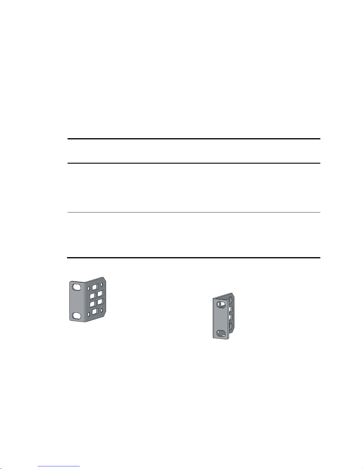
Mounting bracket and cable management bracket kits
Table 5 describes the mounting bracket and cable management bracket kits shipped with the switch.
Table 5 Mounting bracket and cable management bracket kits
Chassis Mounting brackets
Cable
management
brackets
Bracket view
• All 5800 switches except the
5800-48G-PoE+ (2 slots) and
5800-48G-PoE+ TAA (2 slots)
• 5820AF-24XG
• 5820X-24XG-SFP+
• 5820X-24XG-SFP+ TAA
One pair of 1U mounting
brackets (supplied with
the switch)
N/A See Figure 2.
• 5800-48G-PoE+ (2 slots)
• 5800-48G-PoE+ TAA (2 slots)
• 5820X-14XG-SFP+ (2 slots)
• 5820X-14XG-SFP+ TAA (2 slots)
One pair of 2U mounting
brackets (supplied with
the switch)
One pair
(standard)
The mounting
brackets and cable
management
brackets are secured
together by default
(see Figure 3).
Figure 2 1U mounting bracket kit
Page 14
8
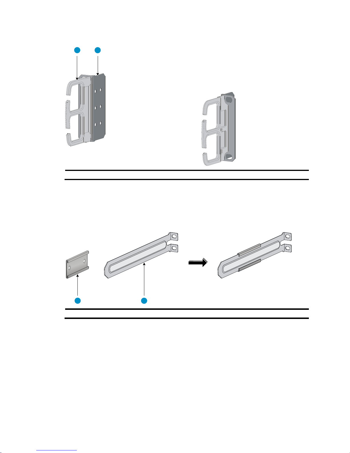
Figure 3 2U cable management bracket and mounting bracket kit
(1) Cable management bracket (2) Mounting bracket
Rack mounting rail kit
The 5800AF-48G and 5820AF-24XG switches come with a pair of chassis rails and a pair of slide rails.
Figure 4 Rack mounting rail kit
(1) Chassis rail (2) Slide rail
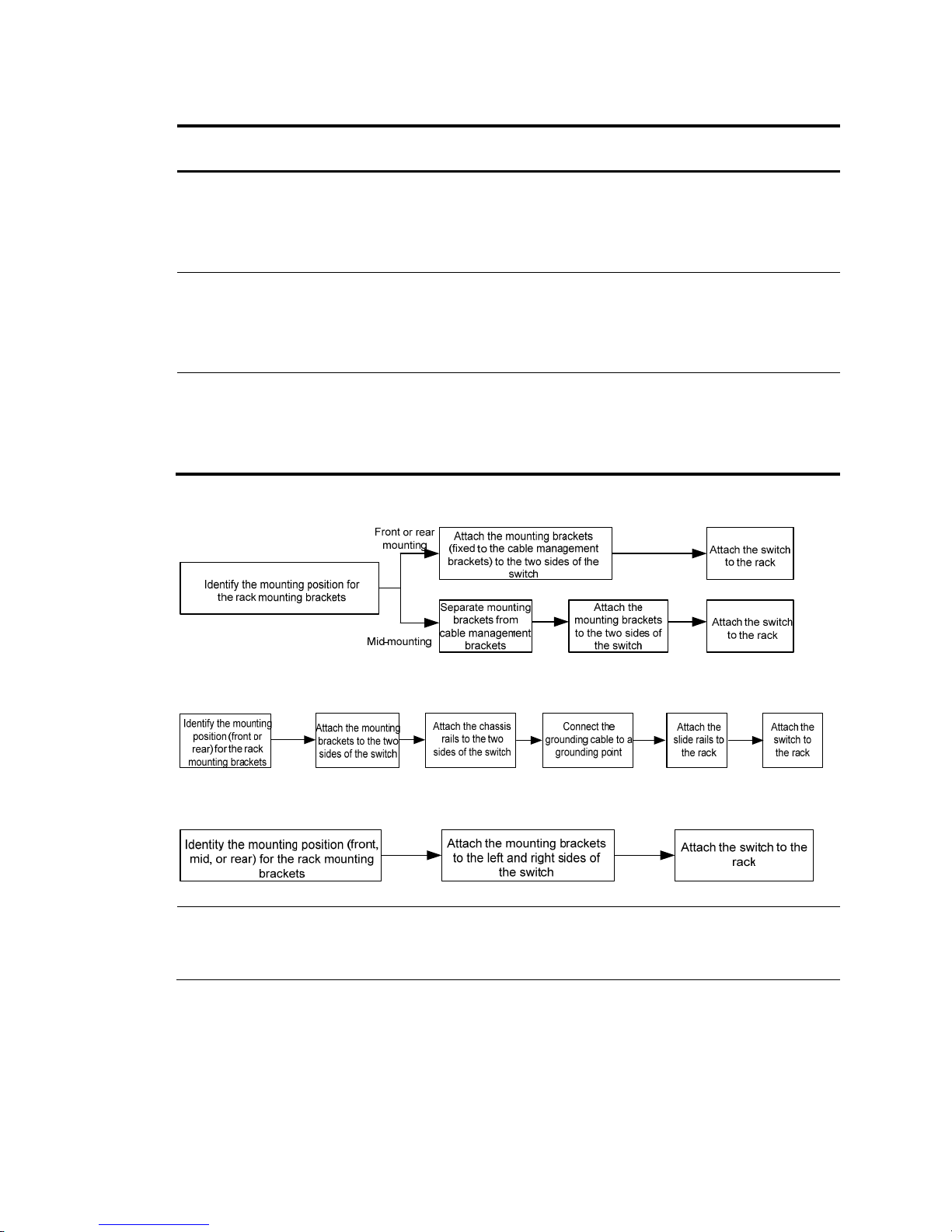
Rack-mounting procedures at a glance
You can install the switch in a 19-inch rack by using different rack mounting positions. Use Table 6 to
identify the rack-mounting procedure for your switch.
1 2
1 2
Page 15
9
Table 6 Rack-mounting procedures at a glance
Chassis
Procedure
dia
g
ram
Procedure references
• 5800-48G-PoE+ (2 slots)
• 5800-48G-PoE+ TAA (2 slots)
• 5820X-14XG-SFP+ (2 slots)
• 5820X-14XG-SFP+ TAA (2 slots)
Figure 5
1. Attaching the mounting brackets to the chassis (for
all the switches except the
5800AF-48G/5820AF-24XG).
2. Rack-mounting a 5800/5820X switch except the
5
800AF-48G/5820AF-24XG.
• 5800AF-48G
• 5820AF-24XG
Figure 6
1. Attaching the mounting brackets, chassis rails, and
gr
ounding cable to the chassis
(5800AF-48G/5820AF-24XG).
2. Rack-mounting a 5800AF-48G/5820AF-24XG
swi
tch.
• All other 5800 switches
• 5820X-24XG-SFP+
• 5820X-24XG-SFP+ TAA
Figure 7
1. Attaching the mounting brackets to the chassis (for
all the s
witches except the
5800AF-48G/5820AF-24XG).
2. Rack-mounting a 5800/5820X switch except the
5
800AF-48G/5820AF-24XG.
Figure 5 Rack-mounting procedure (1)
Figure 6 Rack-mounting procedure (2)
Figure 7 Rack-mounting procecure (3)
NOTE:
If a rack shelf is available, you can put the switch on the rack shelf, slide the switch to an appropriate
location, and attach the switch to the rack with the mounting brackets.
Page 16
10
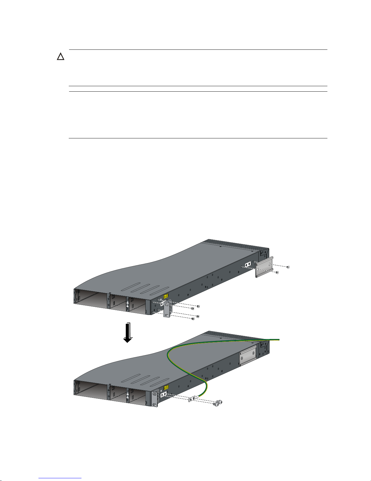
Attaching the mounting brackets, chassis rails, and grounding
cable to the chassis (5800AF-48G/5820AF-24XG)
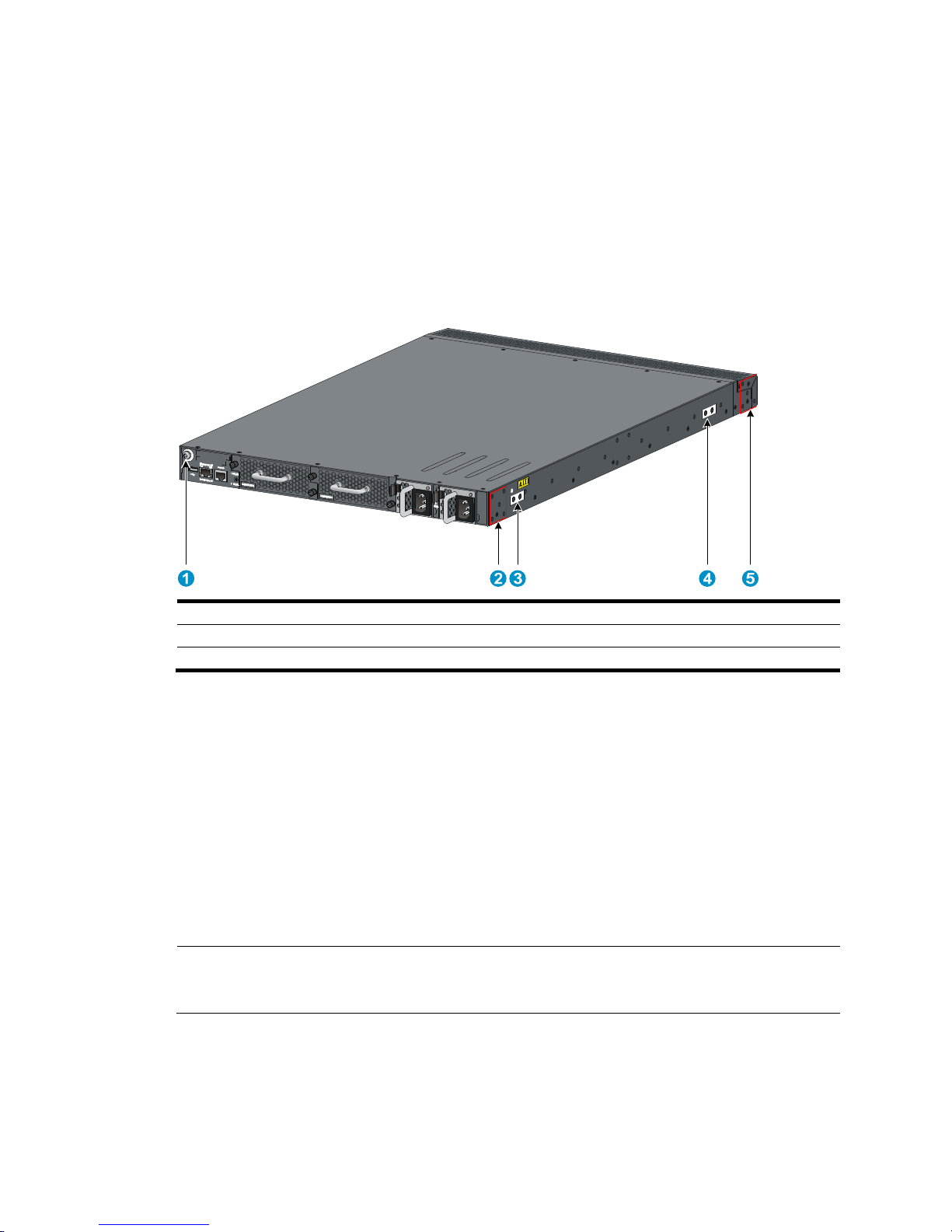
The 5800AF-48G and 5820AF-24XG switches have one front mounting position (near the network ports)
and one rear mounting position (near the power supplies). The switches also have one primary
grounding point (with a grounding sign) and two auxiliary grounding points. Use the primary grounding
point whenever possible. If the primary grounding point fails or is not suitable for the installation site, use
one of the auxiliary grounding points.
Figure 8 Identifying the mounting and grounding positions
(1) Auxiliary grounding point 2 (2) Rear mounting position
(3) Primary grounding point (4) Auxiliary grounding point 1
(5) Front mounting position
Attaching the mounting brackets and chassis rails to the chassis
1. Align the mounting brackets with the screw holes in the rear mounting position (see Figure 9) or
front mounting position (see Figure 10).
2. Use M4
screws (supplied with the switch) to attach the mounting brackets to the chassis.
3. Align the chassis rails with the rail mounting holes in the chassis:
{ If the mounting brackets are in the rear mounting position, align the chassis rails with the screw
holes at the front of the side panels (see Figure 9).
{ If the mounting brackets are in the front mounting position, align the chassis rails with the screw
holes at the rear of the side panels (see Figure 10).
4. Use M4 screws (supplied with the switch) to attach the chassis rails to the chassis.
NOTE:
Secure the mounting brackets and chassis rails to both sides of the chassis in the same way.
Page 17
11
Connecting the grounding cable to the chassis
CAUTION:
The primary grounding point and auxiliary grounding point 1 are located on the left side panel. If you use
one of these grounding points, you must connect the grounding cable to the grounding point before you
mount the switch in the rack.
NOTE:
• HP recommends that you use the primary grounding point or auxiliary
g
rounding point 1 because the
grounding cable and grounding screw that come with the switch are suitable only for these two
grounding points.
• To use auxiliary grounding point 2, you must prepare a grounding cable yourself.
To connect the grounding cable to a chassis grounding point, for example, the primary grounding point:
1. Choose a grounding point.
2. Unpack the grounding cable and grounding screws.
You can use the cable and screws shipped with the switch only for connecting to the primary
grounding point or auxiliary grounding point 1.
3. Align the two-hole grounding lug at one end of the cable with the grounding holes of the
grounding point, insert the grounding screws into the holes, and tighten the screws with a
screwdriver to attach the grounding lug to the chassis, as shown in Figure 9.
Figure 9 Attaching th
e rear mounting brackets/chassis rails/grounding cable to the chassis
Page 18
12
Figure 10 Attaching the front mounting brackets/chassis rails to the chassis
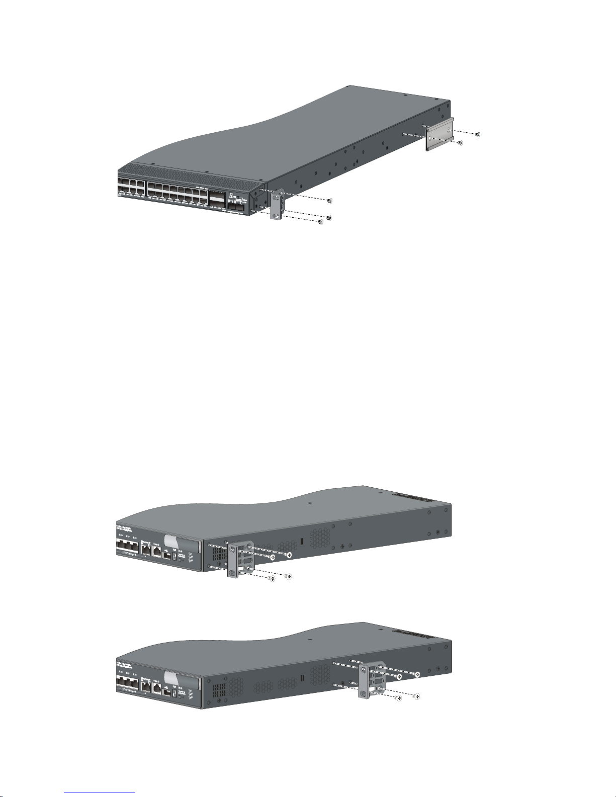
Attaching the mounting brackets to the chassis (for all the
switches except the 5800AF-48G/5820AF-24XG)
All 5800 and 5820X switches except the 5800AF-48G and the 5820AF-24XG have three mounting
positions: one front mounting position (near the network ports), one mid-mounting position, and one rear
mounting position (near the power supplies).
To attach the mounting brackets in one of these positions:
1. Align one mounting bracket with the screw holes in the front-mounting position (Figure 11),
mid-mount
ing position (Figure 12), or the
rear-mounting position (Figure 13).
These figures show attaching a 1U bracket to a 1U switch chassis. To attach a 2U bracket to a 2U
switch chassis, see Figure 14.
2. Use M4
screws (supplied with the switch) to attach the mounting bracket to the chassis.
3. Repeat the proceeding steps to attach the other mounting bracket to the chassis.
Figure 11 1U mounting bracket front mounting position
Figure 12 1U bracket mid-mounting position
Page 19
13
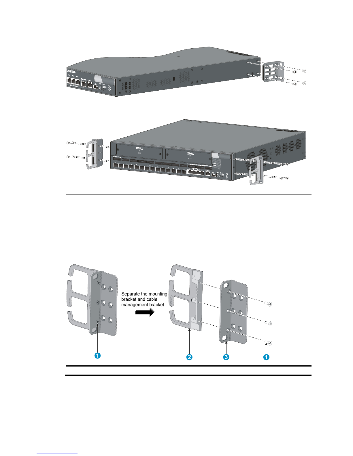
Figure 13 1U bracket rear mounting position
Figure 14 2U bracket front mounting position
NOTE:
• Installing the 2U mounting brackets in the rear mounting position is the same as installin
g
the brackets
in the front mounting position.
• To install the 2U mounting brackets in the mid-mounting position of a 2U switch chassis, first use a
screwdriver to loosen the three captive screws and separate the mounting brackets from the cable
management brackets (see Figure 15).
Figure 15 Separating a cable management bracket from a mounting bracket
(1) Captive screws (2) Cable management bracket (3) Mounting bracket
Page 20
14
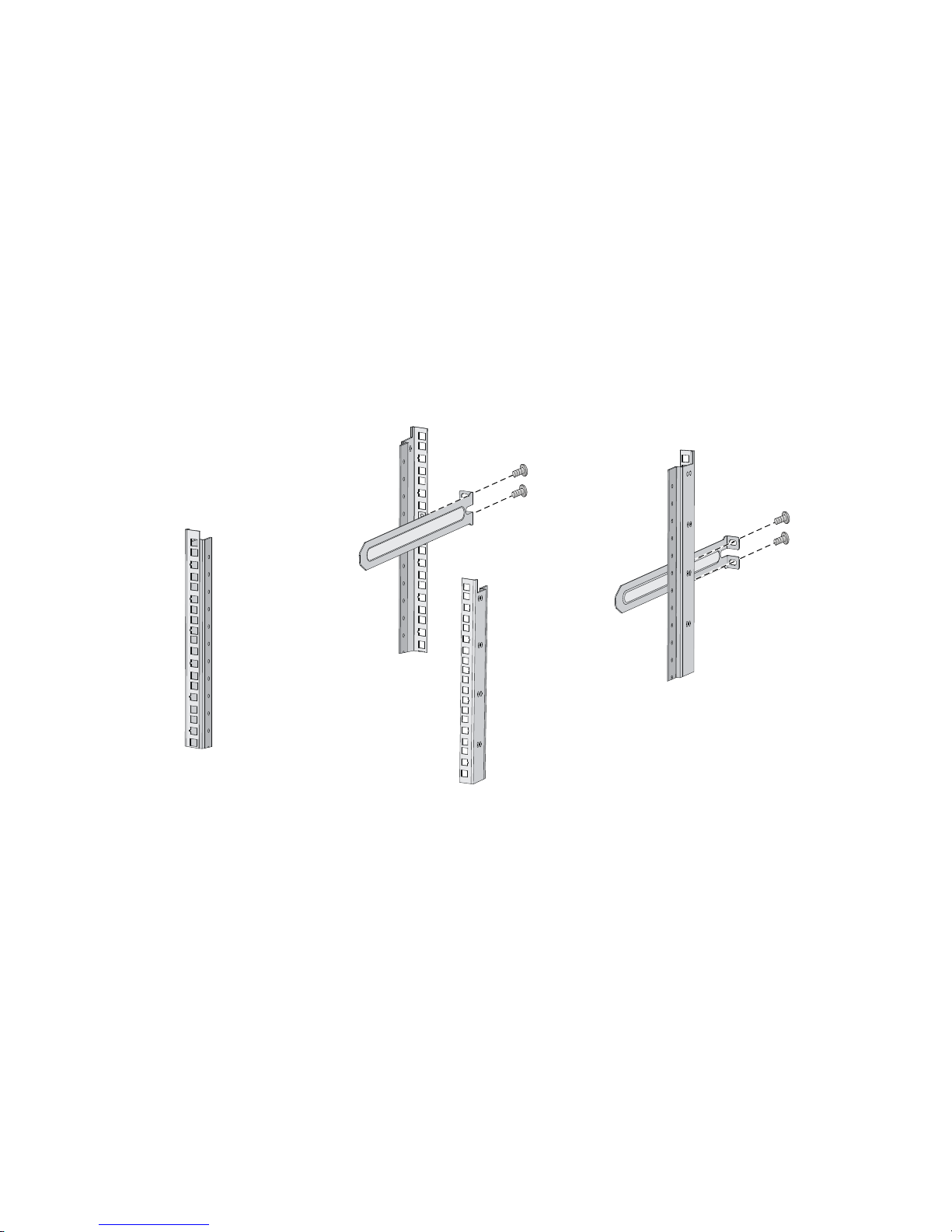
Rack-mounting a 5800AF-48G/5820AF-24XG switch
Attaching the slide rails to the rack
You must install slide rails for rack-mounting a 5800AF-48G or 5820AF-24XG switch.
To attach the slide rails to the rack:
1. Identify the rack attachment position for the slide rails.
2. Install cage nuts (user-supplied) in the mounting holes in the rack posts.
3. Align the screw holes in one slide rail with the cage nuts in the rack post on one side, and use
screws (user supplied) to attach the slide rail to the rack, as shown in Figure 16.
4. Repeat the pr
eceding step to attach the other slide rail to the rack post on the other side.
Keep the two slide rails at the same height so the slide rails can attach into the chassis rails.
Figure 16 Installing the slide rails
Mounting the switch in the rack
This task requires two people. To mount the switch in the rack:
1. Wear an ESD wrist strap and make sure it makes good skin contact and is correctly grounded.
2. Verify that the mounting brackets and chassis rails have been securely attached on the two sides
of the switch.
3. Verify that the slide rails have been correctly attached to the rear rack posts.
4. Install cage nuts (user-supplied) to the front rack posts and make sure they are at the same level as
the slide rails.
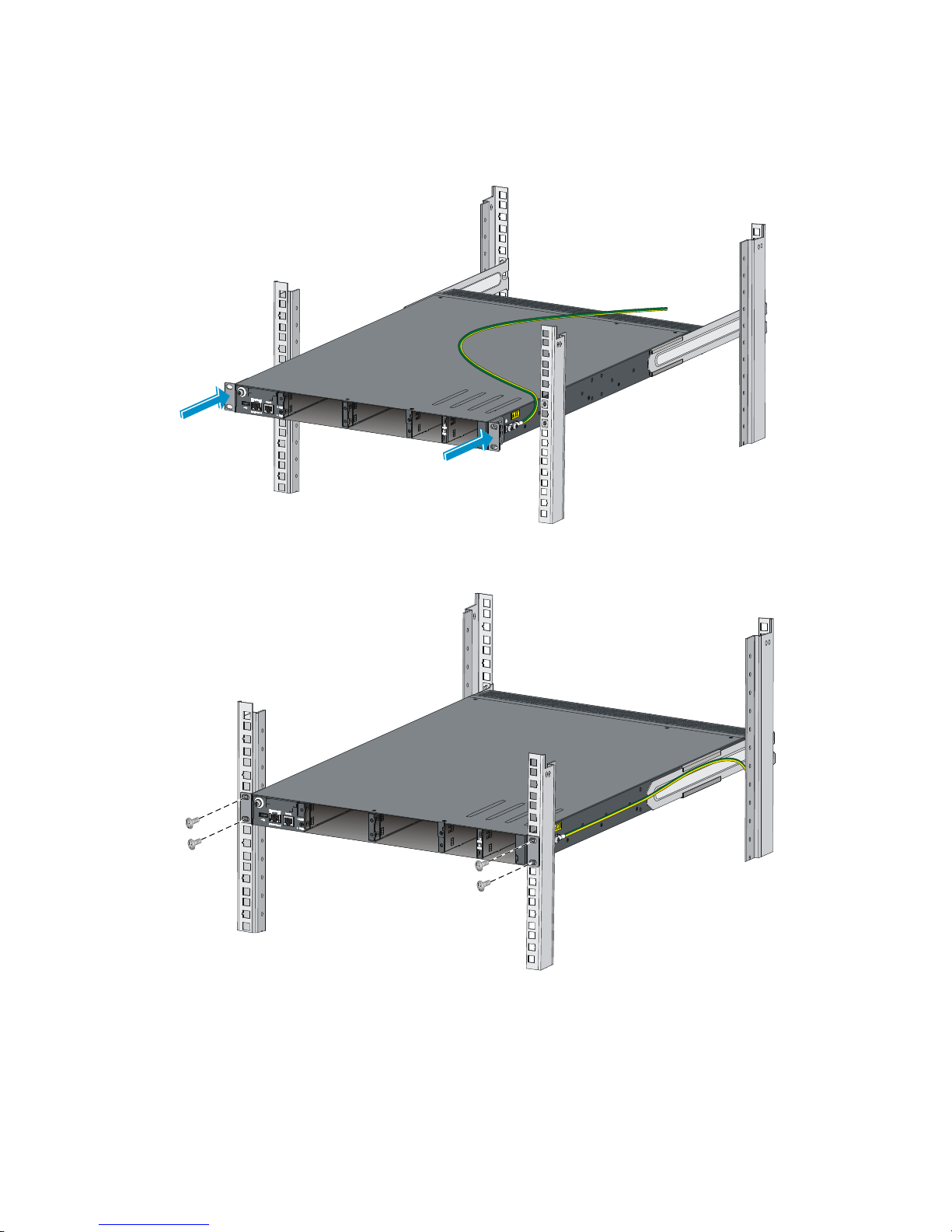
5. Supporting the bottom of the switch, align the chassis rails with the slide rails on the rack posts, as
shown in Figure 17. Work with another person to slid
e the chassis rails along the slide rails until
the mounting brackets are flush with the rack posts.
6. Use screws (user-supplied) to attach the mounting brackets to the rack, as shown in Figure 18.
Page 21
15
To secure the switch in the rack, make sure the front ends of the slide rails reach out of the chassis
rails.
Figure 17 Mounting the switch in the rack (1)
Figure 18 Mounting the switch in the rack (2)
Rack-mounting a 5800/5820X switch except the
5800AF-48G/5820AF-24XG
This installation task requires two people. To mount the switch in the rack:
Page 22
16
1. Wear an ESD wrist strap and make sure it makes good skin contact and is correctly grounded.
2. Verify that the mounting brackets have been securely attached to the switch chassis.
3. Install cage nuts (user-supplied) in the mounting holes in the rack posts.
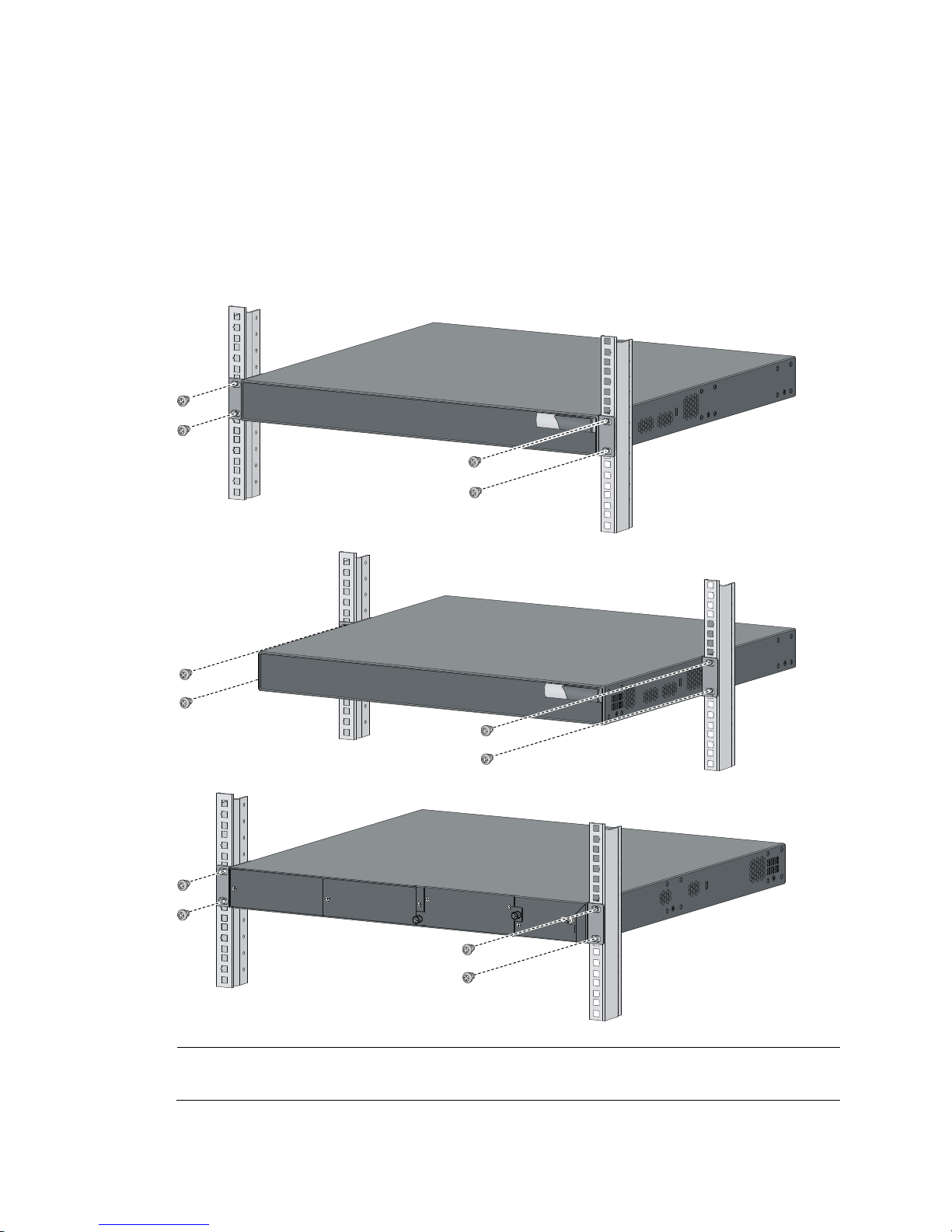
4. One person holds the switch chassis and aligns the mounting brackets with the mounting holes in
the rack posts, and the other person attaches the mounting brackets with screws (user-supplied) to
the rack.
5. Verify that the switch chassis is horizontal and tighten the screws.
Figure 19 Mounting a 1U 5800 switch in a rack
NOTE:
The procedure for rack-mounting a 2U switch is the same as rack-mounting a 1U switch.
Page 23

17
Mounting the switch on a workbench
IMPORTANT:
• Ensure good ventilation and 10 cm (3.9 in) of clearance around the chassis for heat dissipation.
• Avoid placing heavy objects on the switch.
To mount the switch (except the 5800AF-48G and the 5820AF-24XG) on a workbench:
1. Verify that the workbench is sturdy and correctly grounded.
2. Place the switch with bottom up, and clean the round holes in the chassis bottom with dry cloth.
3. Attach the rubber feet to the four round holes in the chassis bottom.
4. Place the switch with upside up on the workbench.
Grounding the switch
W
ARNING!
Correctly connecting the switch grounding cable is crucial to lightning protection and EMI protection.
The power input end of the switch has a noise filter, whose central ground is directly connected to the
chassis to form the chassis ground (commonly known as PGND). You must securely connect this chassis
ground to the earth so the faradism and leakage electricity can be safely released to the earth to
minimize EMI susceptibility of the switch.
You can ground a switch by using a grounding strip at the installation site or the AC power cord
connected to the switch.
NOTE:
The power and grounding terminals in this section are for illustration only.
Grounding the switch with a grounding strip
W
ARNING!
Connect the
g
rounding cable to the grounding system in the equipment room. Do not connect it to a fire
main or lightning rod.
If a grounding strip is available at the installation site, connect the grounding cable to the grounding
strip.
Grounding a 5800AF-48G/5820AF-24XG switch
To connect the grounding cable:
1. Attach the two-hole grounding lug at one end of the grounding cable to a grounding point on the
switch chassis (see "Connecting the grounding cable to the chassis").
2. Remove the hex nut of a grounding post on the grounding strip.
3. Attach the ring terminal at the other end of the grounding cable to the grounding strip through the
grounding post, and fasten the ring terminal with the removed hex nut.
Page 24
18
Figure 20 Connecting the grounding cable to a grounding strip
(1) Hex nut (2) Ring terminal
(3) Grounding post (4) Grounding strip
NOTE:
• HP recommends that you use the primary grounding point or auxiliary grounding point 1, because the
grounding cable and grounding screw provided with the switch are applicable only to these two
grounding points.
• To use auxiliary grounding point 2, you must prepare a grounding cable yourself. The connection
method is the same as connecting to the other two grounding points.
Grounding a 5800/5820X switch except the 5800AF-48G/5820AF-24XG
All 5800 and 5820X switches except the 5800AF-48G and the 5820AF-24XG have a grounding point
(with a grounding sign) on their rear panels.
To connect the grounding cable:
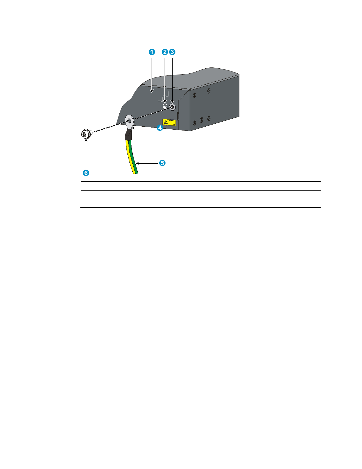
1. Remove the grounding screw from the rear panel of the switch chassis.
2. Attach the grounding screw to the ring terminal of the grounding cable.
3. Use a screwdriver to fasten the grounding screw into the grounding screw hole.
Page 25
19
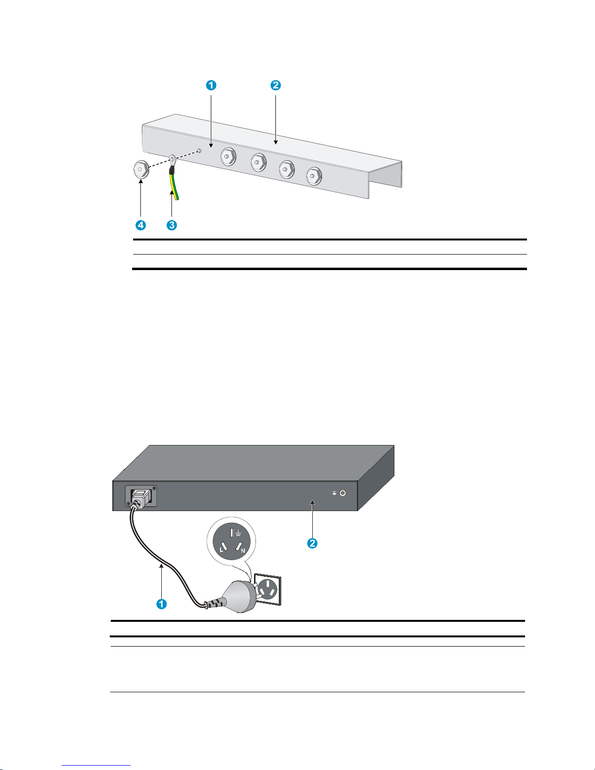
Figure 21 Connecting the grounding cable to the grounding hole of switch
(1) Chassis rear panel (2) Grounding sign
(3) Grounding hole (4) Ring terminal
(5) Grounding cable (6) Grounding screw
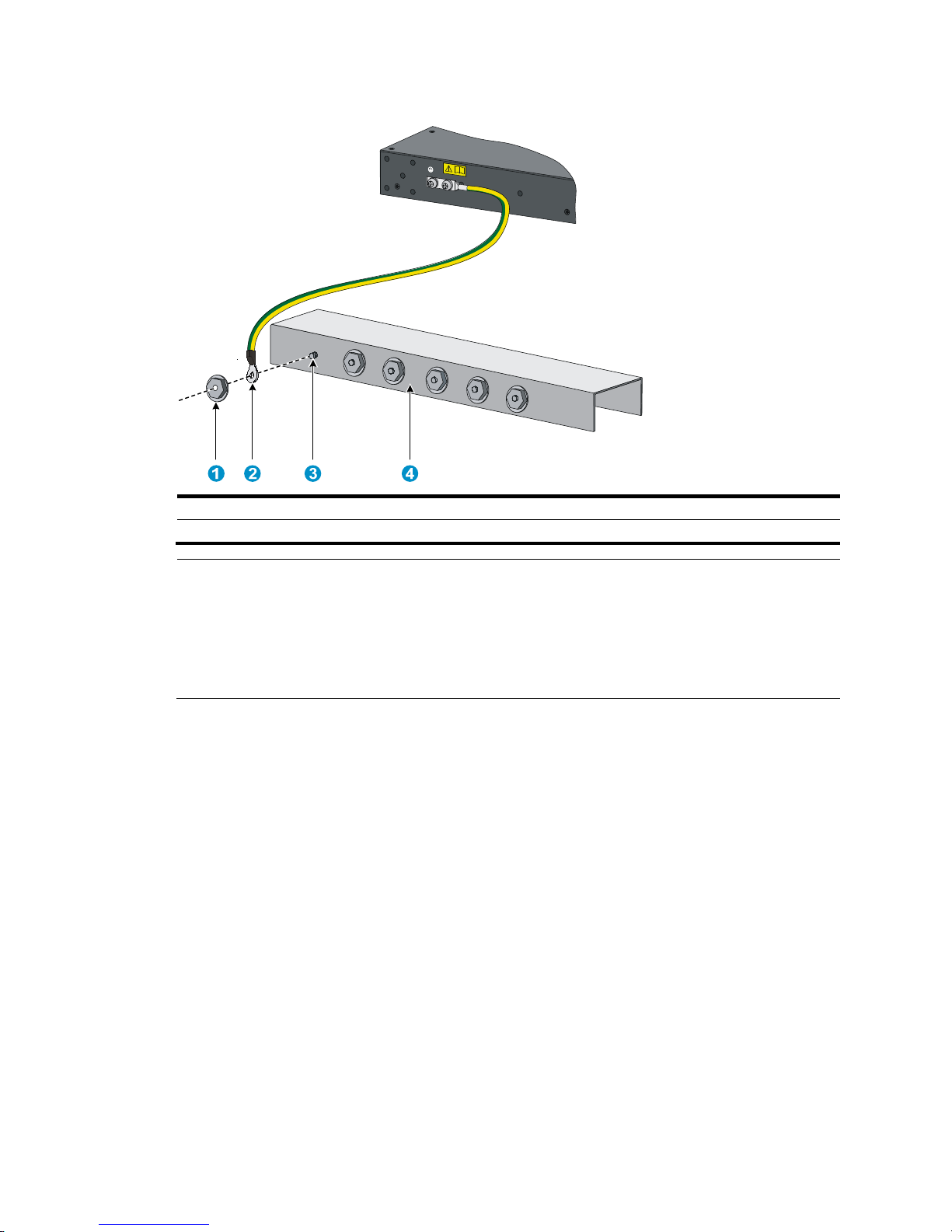
4. Remove the hex nut of a grounding post on the grounding strip.
5. Cut the grounding cable as appropriate for connecting to the grounding strip.
6. Peel 5 mm (0.20 in) of insulation sheath by using a wire stripper, and insert the bare metal part
through the black insulation covering into the end of the ring terminal.
The switch comes with two ring terminals. Select the ring terminal appropriate to the size of the
grounding post.
7. Secure the metal part of the cable to the ring terminal with a crimper, cover the joint with the
insulation covering, and heat the insulation covering with a blow dryer to completely cover the
metal part.
8. Connect the ring terminal to the grounding post of the grounding strip, and fasten it with the
removed hex nut.
Page 26
20
Figure 22 Connecting the grounding cable to a grounding strip
(1) Grounding post (2) Grounding strip
(3) Grounding cable (4) Hex nut
Grounding the switch by using the AC power cord
If the installation site has no grounding strips, ground an AC-powered switch through the protective earth
(PE) wire of the power cord. Make sure that:
• The power cord has a PE terminal.
• The ground contact in the power outlet is securely connected to the ground in the power distribution
room or on the AC transformer side.
• The power cord is securely connected to the power outlet. If the ground contact in the power outlet
is not connected to the ground, report the problem and reconstruct the grounding system.
Figure 23 Grounding through the PE wire of the AC power cord
(1) Three-wire AC power cable (2) Chassis rear panel
NOTE:
To guarantee the grounding effect, use the grounding cable provided with the switch to connect to the
grounding strip in the equipment room as long as possible.
Page 27

21
Installing/removing a fan tray
CAUTION:
The 5800-48G-PoE+ (2 slots), 5800-48G-PoE+ TAA (2 slots), 5800-24G-SFP (1 slot), and
5800-24G-SFP TAA (1 slot) switches, and all 5820X switches except the 5820AF-24XG have only one
fan tray slot. To ensure good ventilation, follow these guidelines:
• Do not operate the switch without a fan tray.
• If the fan tray has problems durin
g
operation, replace it within 2 minutes while the switch is operating.
CAUTION:
The 5800AF-48G and 5820AF-24XG switches require two same direction air flow fan trays to function
correctly.
• Do not operate the system with only one fan tray for more than 24 hours.
• Do not operate the system without any fan tray for more than 2 minutes.
• Do not operate the system outside of the temperature range 0°C to 45°C (32°F to 113°F) degrees.
Failure to comply with these operating requirements might void the warranty.
Installing a fan tray
CAUTION:
To prevent damage to the fan tray or the connectors on the backplane, insert the fan tray gently. If you
encounter resistance while inserting the fan tray, pull out the fan tray and insert it again.
To install a fan tray:
1. Wear an ESD wrist strap and make sure it makes good skin contact and is correctly grounded.
2. Unpack the fan tray and verify that the fan tray model is correct.
3. Grasp the handle of the fan tray with one hand and support the fan tray bottom with the other, and
slide the fan tray along the guide rails into the slot until the fan tray seats in the slot and has a firm
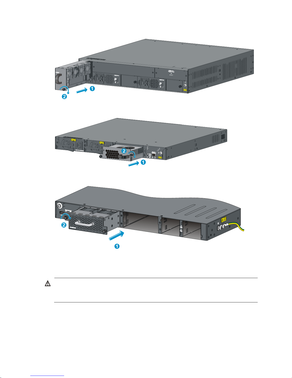
contact with the backplane (see callout 1 in Figure 24, Figure 25, or Figure 26).
4. Fasten the captive screw on the fan tray with a Phillips screwdriver until the fan tray is securely
seated in the chassis (see callout 2 in Figure 24, Figure 25, or Figure 26).
If the captive screw cannot be tightly fastened, examine the installation of the fan tray.
Page 28
22
Figure 24 Installing an LSW1FAN fan tray
Figure 25 Installing an LSW1BFAN fan tray
Figure 26 Installing an LSWM1FANSC or LSWM1FANSCB fan tray
Removing a fan tray
W
ARNING!
• Take out the fan tray after the fans completely stop rotating.
• To avoid an unbalanced fan causing loud noise, do not touch the fans, even if they are not rotating.
To remove a fan tray:
1. Wear an ESD wrist strap and make sure it makes good skin contact and is correctly grounded.
2. Loosen the captive screw of the fan tray with a Phillips screwdriver until it is fully disengaged from
the switch chassis.
Page 29
23
3. Grasp the handle of the fan tray with one hand and pull the fan tray part way out the slot. Support
the fan tray bottom with the other hand, and pull the fan tray slowly along the guide rails out of the
slot.
4. Put away the removed fan tray in an antistatic bag for future use.
Installing/removing a power supply
W
ARNING!
In power redundancy mode, you can replace a power supply without powering off the switch but must
strictly follow the installation and procedures in Figure 27 and Figure 28 to avoid a
ny bodily injury or
damage to the switch.
The 5800-48G-PoE+ (2 slots), 5800-48G-PoE+ TAA (2 slots), 5800-24G-SFP (1 slot), and
5800-24G-SFP TAA (1 slot) switches, and all the 5820X switches except the 5820AF-24XG come with
power supply slot 1 empty and power supply slot 2 covered by a filler panel. The 5800AF-48G and
5820AF-24XG switches come with both power supply slots empty and the power filler modules as
accessories.
You can install one or two power supplies for these switches as needed. For more information about the
power supplies available for the switches, see "Hot swappable power supplies."
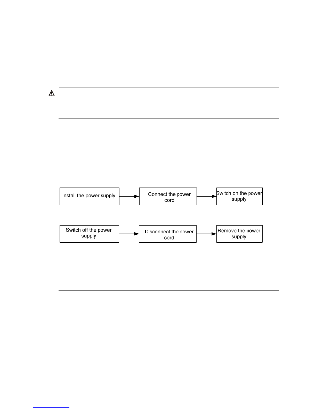
Figure 27 Installation pr
ocedure
Figure 28 Removal procedure
NOTE:
• HP 58x0AF 650W AC power supply is referred to as 650 W AC power supply and HP 58x0AF 650
W
DC power supply is referred to as 650W DC power supply throughout this installation guide.
• HP 58x0AF 300W AC power supply is referred to as 300 W AC power supply and HP 58x0AF 300
W
DC power supply is referred to as 300 W DC power supply throughout this installation guide.
5800AF-48G/5820AF-24XG
Installing a power supply
To install a 650 W AC power supply, 300 W AC power supply, 650 W DC power supply, or 300 W
DC power supply in a 5800AF-48G or 5820AF-24XG switch:
1. Wear an ESD wrist strap and make sure it makes good skin contact and is correctly grounded.
2. Unpack the power supply and verify that the power supply model is correct.
3. Correctly orient the power supply with the power supply slot (see Figure 29), grasp
the handle of
the power supply with one hand and support its bottom with the other, and slide the power supply
Page 30
24
slowly along the guide rails into the slot until it has firm contact with the connectors on the
backplane.
To prevent damage to the connectors inside the switch chassis, insert the power supply gently. If
you cannot insert the power supply into the slot, re-orient the power supply rather than use
excessive force to push it in.
4. If only one power supply is installed, install a power filler module in the empty power supply slot
for good ventilation of the switch, as shown in Figure 30.
Figure 29 Installing a po
wer supply
Figure 30 Installing a power filler module
Removing a power supply
CAUTION:
If the switch has two power supplies, removing one power supply does not affect the operation of the
switch. If the switch has only one power supply, removing the power supply powers off the switch.
To remove a 650 W AC power supply, 300 W AC power supply, 650 W DC power supply, or 300 W
DC power supply from a 5800AF-48G or 5820AF-24XG switch:
1. Wear an ESD wrist strap and make sure it makes good skin contact and is correctly grounded.
2. Squeeze the tabs on the power cord connector with your thumb and forefinger, and pull the
connector out to remove the power cord, as shown in Figure 31.
3. Hold the handle on the power supply with one hand,
pivot the latch on the power supply to the
right with your thumb, and pull the power supply part way out of the slot, as shown in Figure 32.
4. Su
pporting the power supply bottom with one hand, slowly pull the power supply out with the other
hand.
5. Put away the removed power supply in an antistatic bag for future use.
Page 31

25
NOTE:
The 650 W AC power supply, 300 W AC power supply, 650 W DC power supply, and 300 W DC power
supply do not have a power switch. You do not need to switch on or switch off the power supply as
described in the installation and removal procedures in Figure 27 and Figure 28.
Figure 31 Removing the DC power cord
(1) Press the tabs on the power cord connector with
your thumb and forefin
g
er
(2) Pull the power cord connector out
Figure 32 Removing the power supply
(1) Pivot the latch to the right with your thumb
(2) Pull the power supply out
1
2
Page 32

26
5800-48G-PoE+ (2 slots)/5800-48G-PoE+ TAA (2
slots)/5800-24G-SFP (1 slot)/5800-24G-SFP TAA (1 slot)/all
the 5820X switches but the 5820AF-24XG
Installing a power supply
1. Wear an ESD wrist strap and make sure it makes good skin contact and is correctly grounded.
2. If the power supply slot is covered by a filler panel, remove the filler panel first.
3. Handle the filler module at the rear of the switch:
{ To install the PSR750-A power supply into the 5800-48G-PoE+ (2 slots) or 5800-48G-PoE+ TAA
(2 slots) switch, remove the filler module (see callout 1 and callout 2 in Figure 33).
{ To install the PSR300-12A, PSR300-12A2, PSR300-12D1, or PSR300-12D2 power supply into
the 5800-48G-PoE+ (2 slots) or 5800-48G-PoE+ TAA (2 slots) switch, make sure the filler
module has been installed at the rear of the switch.
4. Unpack the power supply and verify that the power supply model is correct.
5. Correctly orient the power supply with the power supply slot, grasp the handle of the power supply
with one hand and support its bottom with the other, and slide the power supply slowly along the
guide rails into the slot (see callout 1 in Figure 34 or Figure 35).
To prevent damage to the connectors inside the switch chassis, insert the power supply gently. If
you cannot insert the power supply into the slot, re-orient the power supply rather than use
excessive force to push it in.
6. Fasten the captive screws on the power supply with a Phillips screwdriver to secure the power
supply in the chassis (see callout 2 in Figure 34 or Figure 35).
If the captive
screw cannot be tightly attached, examine the installation of the power supply.
7. If you install only one power supply, install the filler panel over the empty power supply slot for
good ventilation.
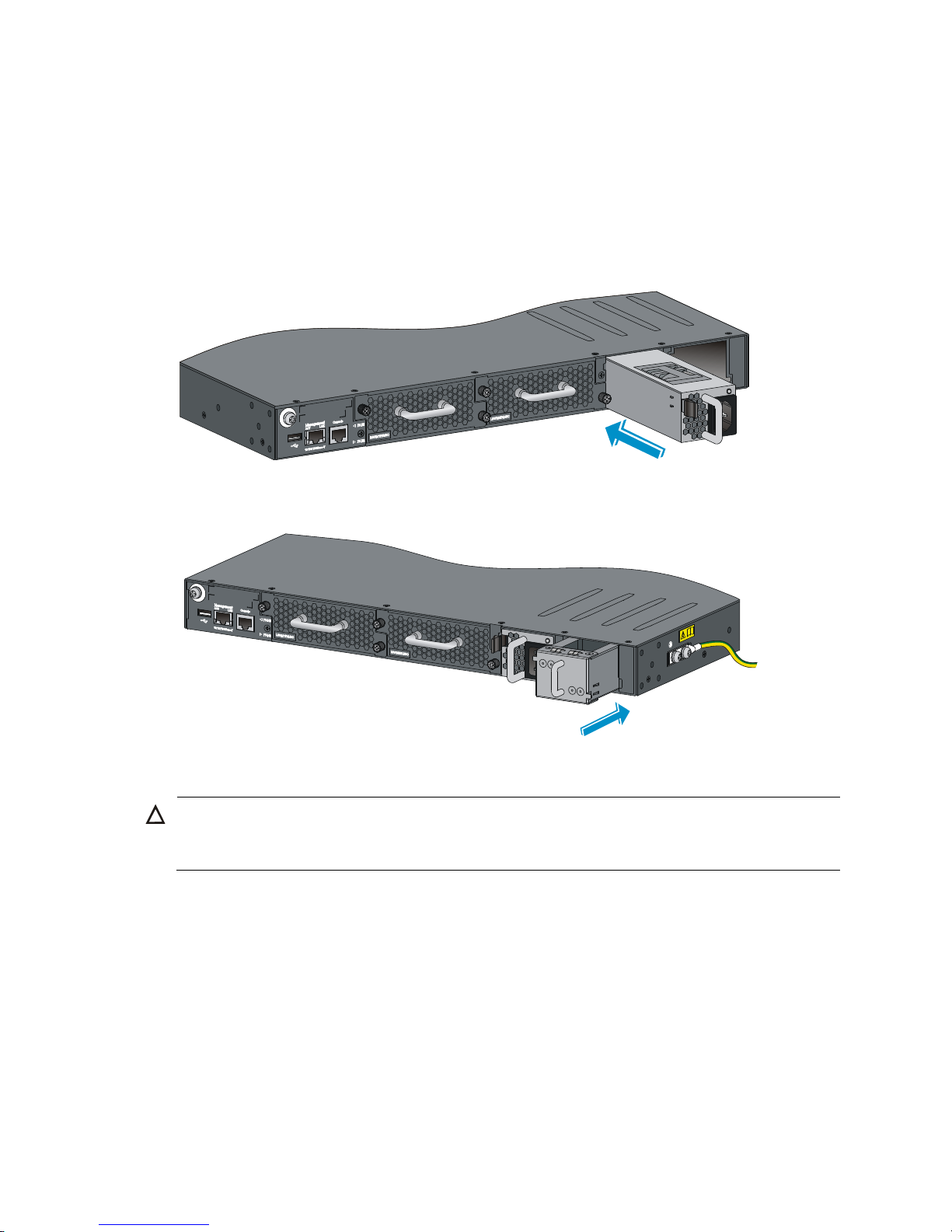
Figure 33 Removing the filler module before installing a PSR750-A power supply
Page 33

27
Figure 34 Installing the PSR750-A power supply
Figure 35 Installing other power supply models
Removing a power supply
1. Wear an ESD wrist strap and make sure it makes good skin contact and is correctly grounded.
2. Switch off the power supply and disconnect the power cord.
3. Loosen the captive screws of the power supply with a Phillips screwdriver until they are completely
disengaged.
4. Grasp the handle of the power supply with one hand and pull it out a little, support the bottom with
the other hand, and pull the power supply slowly along the guide rails out of the slot.
5. Put away the removed power supply in an antistatic bag for future use.
NOTE:
The PSR150-A, PSR150-A1, PSR150-D, and PSR150-D1 power supplies do not have a power switch. You
do not need to switch on or switch off the power supply as described in the installation and removal
procedures in Figure 27 an
d Figure 28.
Page 34

28
Connecting the power cord
Table 7 Power cord connection procedures at a glance
Power su
pply
Connection
p
rocedure reference
Built-in power supply
AC input Connecting an AC power cord to the switch
–54 VDC input (RPS powered) Connecting the switch to a –54 VDC output RPS
12 VDC input (RPS powered) Connecting the switch to a 12 VDC output RPS
Hot swappable power supply
• PSR150-A
• PSR150-A1
Connecting the PSR150-A/PSR150-A1 power supply
• PSR150-D
• PSR150-D1
• –48 VDC input:
Connecting the PSR150-D/PSR150-D1 power supply to a –48 VDC
power source
• –54 VDC input (RPS powered):
Connecting the PSR150-D/PSR150-D1 power supply to a –54 VDC
out
put RPS
• PSR300-12A
• PSR300-12A2
Connecting the PSR300-12A/PSR300-12A2 power supply
• PSR300-12D1
• PSR300-12D2
• –48 VDC input:
Connecting the PSR300-12D1/PSR300-12D2 power supply to a –48
VDC power source
• –54 VDC input (RPS powered):
Connecting the PSR300-12D1/PSR300-12D2 power supply to a –54
VD
C output RPS
PSR750-A Connecting the PSR750-A power supply
• 650 W AC power supply
• 300 W AC power supply
Connecting the 650 W AC/300 W AC power supply
• 650 W DC power supply
• 300 W DC power supply
–48 VDC input:
Connecting the 650 W DC/300 W DC power supply
Connecting an AC power cord to the switch
This section applies to the 5800-48G-PoE+ (1 slot), 5800-48G-PoE+ TAA (1 slot), 5800-24G-PoE+,
5800-24G-PoE+TAA, 5800-48G (1 slot), 5800-48G TAA (1 slot), 5800-24G, and 5800-24G TAA
switches.
To connect an AC power cord to these switches:
1. Connect one end of the AC power cord to the AC-input power receptacle on the switch (see Figure
36 or Figure 37).
2. Connect the other end of th
e power cord to the AC power outlet.
Page 35

29
Figure 36 Connecting the AC power cord to the switch
Figure 37 Connecting the AC power cord to the switch
Connecting the switch to a –54 VDC output RPS
This section applies to the 5800-48G-PoE+ (1 slot), 5800-48G-PoE+ TAA (1 slot), 5800-24G-PoE+, and
5800-24G-PoE+TAA switches.
To connect these switches to the RPS that provides –54 VDC output:
1. Unpack the RPS power cord, identify the plug for connecting to the switch, correctly orient the plug
with the RPS receptacle on the switch chassis, and insert the plug into the receptacle (see callout 1
in Figure 38).
If you cannot insert the plug into the recept
acle, re-orient the plug rather than use excessive force
to push it in.
2. Tighten the screws on the plug with a flat-blade screwdriver to secure the plug in the RPS receptacle
(see callout 2 in Figure 38).
3. Connect the other end of th
e power cord to the RPS.
Page 36

30
Figure 38 Connecting the switch to a –54 VDC output RPS
Connecting the switch to a 12 VDC output RPS
This section applies to the 5800-48G (1 slot), 5800-48G TAA (1 slot), 5800-24G, and 5800-24G TAA
switches.
To connect these switches to the RPS that provides 12 VDC output:
1. Loosen the captive screws on the RPS receptacle and remove the cover, as shown in Figure 39.
Pu
t away the cover and re-install it after you remove the RPS DC-input power connector.
2. Unpack the RPS power cord, identify the plug for connecting to the switch, correctly orient the plug
with the RPS receptacle on the switch chassis, and insert the plug into the receptacle (see callout 1
in Figure 40).
If you cannot insert the plug into the recept
acle, re-orient the plug rather than use excessive force
to push it in.
3. Tighten the screws on the plug with a flat-blade screwdriver to secure the plug in the power
receptacle (see callout 2 in Figure 40).
4. Connect the other end of th
e power cord to the RPS.
Figure 39 Removing the cover over the RPS receptacle
1
2
Page 37

31
Figure 40 Connecting the RPS power cord to the switch
Connecting the PSR150-A/PSR150-A1 power supply
1. Connect one end of the AC power cord supplied with the power supply to the power receptacle on
the power supply (see callout 1 in Figure 41).
2. Connect the other end of the AC power cord to an AC power outlet.
Figure 41 Connecting the PSR150-A power supply
Connecting the PSR150-D/PSR150-D1 power supply to a –48
VDC power source
1. Wear an ESD wrist strap and make sure it makes good skin contact and is correctly grounded.
2. Unpack the DC power cord, correctly orient the plug at one end of the cable with the power
receptacle on the power supply, and insert the plug into the power receptacle (see callout 1
in Figure 42).
If you cannot insert the plug into the recept
acle, re-orient the plug rather than use excessive force
to push it in.
3. Tighten the screws on the plug with a flat-blade screwdriver to secure the plug in the power
receptacle (see callout 2 in Figure 42).
4. Conne
ct the two wires at the other end of the power cord to a –48 VDC power source.
Identify the positive (+) and negative (-) marks on the two wires to avoid connection mistakes.
Page 38

32
Figure 42 Connecting the PSR150-D power supply
Connecting the PSR150-D/PSR150-D1 power supply to a –54
VDC output RPS
1. Unpack the RPS power cord, identify the plug for connecting to the power supply, correctly orient
the plug with the power receptacle on the power supply, and insert the plug into the receptacle
(see callout 1 in Figure 42).
If you cannot insert the plug into the recept
acle, re-orient the plug rather than use excessive force
to push it in.
2. Tighten the screws on the plug with a flat-blade screwdriver to secure the plug in the power
receptacle (see callout 2 in Figure 42).
3. Connect the other end of th
e power cord to the RPS.
Connecting the PSR300-12A/PSR300-12A2 power supply
1. Verify that the AC power supply is off.
2. Connect one end of the AC power cord supplied with the power supply to the power receptacle on
the power supply (see Figure 43).
3. Connect the other end of the power cord to an AC power outlet.
1
2
2
Page 39

33
Figure 43 Connecting the PSR300-12A power supply
Connecting the PSR300-12D1/PSR300-12D2 power supply to
a –48 VDC power source
1. Verify that the DC power supply is off.
2. Unpack the DC power cord, correctly orient the plug at one end of the cable with the power
receptacle on the power supply, and insert the plug into the receptacle (see callout 1 in Figure 44).
If you cannot insert the plug into the recept
acle, re-orient the plug rather than use excessive force
to push it in.
3. Tighten the screws on the plug with a flat-blade screwdriver to secure the plug in the power
receptacle (see callout 2 in Figure 44).
4. Conne
ct the two wires at the other end of the power cord to the –48 VDC power source.
Identify the positive (+) and negative (-) marks on the two wires to avoid connection mistakes.
Figure 44 Connecting the PSR300-12D1 power supply
1
2
2
Page 40

34
Connecting the PSR300-12D1/PSR300-12D2 power supply to
a –54 VDC output RPS
1. Unpack the RPS power cord, identify the plug for connecting to the power supply, orient the plug
with the power receptacle on the power supply, and insert the plug into the receptacle (see callout
1 in Figure 44).
If you cannot insert the plug into the recept
acle, re-orient the plug rather than use excessive force
to push it in.
2. Tighten the screws on the plug with a flat-blade screwdriver to secure the plug in the power
receptacle (see callout 2 in Figure 44).
3. Connect the other end of th
e power cord to the RPS.
Connecting the PSR750-A power supply
1. Verify that the AC power supply is off.
2. Connect one end of the AC power cord supplied with the power supply to the power receptacle on
the power supply (see Figure 45).
3. Connect the other end of the power cord to an AC power outlet.
Figure 45 Connecting the PSR750-A power supply
Connecting the 650 W AC/300 W AC power supply
1. Insert the female connector of the AC power cord supplied with the power supply into the power
receptacle on the power supply.
2. Use a cable tie to secure the power cord to the handle of the power supply, as shown in Figure 46.
3. Connec
t the other end of the power cord to an AC power outlet.
Page 41

35
Figure 46 Connecting the 650 W AC/300 W AC power supply
(1) Cable tie
(2) Tighten the cable tie to secure the power cord to the handle of the power supply
Connecting the 650 W DC/300 W DC power supply
1. Unpack the DC power cord, identify the plug for connecting to the power supply, orient the plug
with the power receptacle on the power supply, and insert the plug into the receptacle (see Figure
47).
If you cannot insert the plug into the recept
acle, re-orient the plug rather than use excessive force
to push it in.
2. Use a cable tie to secure the power cord to the handle of the power supply, as shown in Figure 46.
3. Connect the other end of th
e power cord to the DC power source.
Figure 47 Connecting the 650 W DC/300 W DC power supply
Installing/removing an interface card
This section applies to the 5800 and 5820X switches that have expansion interface slots. For the
interface cards available for the switches, see "Interface cards."
This section uses the LSW1SP4P0 interface card as an example to describe the procedures of installing
and removing an interface card.
Page 42

36
Installing an interface card
1. Wear an ESD wrist strap and make sure it makes good skin contact and is correctly grounded.
2. Loosen the mounting screws on the filler panel over the interface card slot with a Phillips
screwdriver and remove the filler panel.
Figure 48 Removing the filler panel from an interface card slot
(1) Phillips screwdriver (2) Chassis front panel
(3) Filler panel
3. Put away the removed filler panel for future use.
4. Unpack the interface card and make sure the ejector levers are perpendicular to the card panel.
5. Gently push the interface card in along the slot guide rails until the interface card has good contact
with the switch chassis, and push the ejector levers inward.
Figure 49 Installing an interface card
(1) Chassis front panel (2) Interface card
(3) Push the interface card (4) Push the ejector levers inward
Page 43

37
6. Tighten the captive screws with a Phillips screwdriver to secure the interface card in the slot.
Removing an interface card
CAUTION:
Do not touch the surface-mounted components directly with your hands.
1. Wear an ESD wrist strap and make sure it makes good skin contact and is correctly grounded.
2. Use a Phillips screwdriver to completely loosen the captive screws at both sides of the interface
card.
Do not use excessive force during the operation.
3. Pull the ejector levers at both sides of the interface card outward, and pull the interface card along
the guide rails until it completely comes out of the switch chassis.
4. If no new card is to be installed, install the filler panel to prevent dust and ensure good ventilation
in the switch.
Figure 50 Removing an interface card
(1) Chassis front panel (2) Interface card
(3) Pull the ejector levers outward (4) Pull out the interface card
Installing/removing an OAP card
Before you install an OAP card, verify the compatibility of the OAP card with your switch and identify in
which slot you can install the OAP card (see "OAP card compatibility matrix" and "OAP cards")
.
Installing an OAP card in the OAP card slot
CAUTION:
Do not touch the surface-mounted components directly with your hands.
To install an OAP card in the OAP card slot:
1. Wear an ESD wrist strap and make sure it makes good skin contact and is correctly grounded.
2. Loosen the captive screws on the filler panel over the OAP card slot with a Phillips screwdriver
(see Figure 51), and remove the filler panel.
Page 44

38
Do not use excessive force when you install the OAP card. If you cannot insert the OAP card
smoothly, examine the installation method for mistakes.
Figure 51 Removing the filler panel from the OAP card slot
(1) Rotate counterclockwise (2) Filler panel in the OAP card slot (3) Phillips screwdriver
3. Put away the removed filler panel for future use.
4. Unpack the OAP card and verify that this OAP card can be installed in the OAP card slot.
5. Hold the OAP card with the ejector levers on top, push the OAP card slowly along the guide rails
into the slot (see callout 3 in Figure 52), and push the ej
ector levers inward to lock the OAP card
in position (see callout 4 in Figure 52).
Figure 52 Installing an OAP card
(1) OAP card
(2) Chassis rear panel
(3) Push the OAP card (4) Push the ejector levers inward
6. Fasten the captive screws on the OAP card with the Phillips screwdriver to secure the OAP card in
the slot.
Page 45

39
Removing the OAP card in the OAP card slot
W
ARNING!
Do not touch the protection cover marked by the yellow warning label on the OAP card.
Underneath this protection cover is a heat radiator. After the OAP card runs for a period of time, this area
can get too hot to touch with bare hands.
CAUTION:
Do not touch the surface-mounted components directly with your hands.
To remove the card in the OAP card slot:
1. Wear an ESD wrist strap and make sure it makes good skin contact and is correctly grounded.
2. Loosen the captive screws on the OAP card with the Phillips screwdriver until all spring pressure is
released. Do not use excessive force.
3. Pull the ejector levers outward (see callout 3 in Figure 53), and pull out the OAP ca
rd slowly along
the guide rails (see callout 4 in Figure 53).
4. If you do not install a new
OAP card in the slot, install a filler panel to prevent dust from entering
the switch and ensure good ventilation in the switch.
Figure 53 Removing the OAP card
(1) OAP card (2) Chassis rear panel
(3) Pull the ejector levers outward (4) Pull out the OAP card
Installing an OAP card in an expansion interface card slot
Unpack the OAP card and verify that the card can be installed in an expansion interface card slot (see
"OAP cards")
.
Follow the procedure described in "Installing an interface card" to inst
all the OAP card in an expansion
interface card slot.
Page 46

40
Removing the OAP card in an expansion interface card slot
See "Removing an interface card."
Installing/removing a PoE module
You can install a hot swappable PoE module (LSW148POEM) in a 5800-48G-PoE+ (2 slots) or
5800-48G-PoE+ TAA (2 slots) switch to supply power to devices such as IP telephones, wireless LAN
access points (APs), and web cameras through Ethernet ports over twisted pair cable.
Installing a PoE module
1. Wear an ESD wrist strap and make sure it makes good skin contact and is correctly grounded.
2. Loosen the captive screws on the filler panel over the PoE module slot with a Phillips screwdriver
and remove the filler panel.
3. Put away the removed filler panel for future use.
4. Unpack the PoE module.
5. Push the PoE module slowly along the guide rails into the slot (see callout 1 in Figure 54) and pu
sh
the ejector levers inward to lock the PoE module in position (see callout 2 in Figure 54).
Do not use excessive force.
6. Fasten the captive screws on the PoE module with a Phillips screwdriver to securely fix the PoE
module in the slot.
Figure 54 Installing a PoE module
Removing the PoE module
1. Wear an ESD wrist strap and make sure it makes good skin contact and is correctly grounded.
2. Use a Phillips screwdriver to completely loosen the captive screws on the PoE module.
3. Pull the ejector levers outward (see callout 1 in Figure 55). Then pull
out the PoE module slowly
along the guide rails (see callout 2 in Figure 55).
Do not us
e excessive force.
1
2
Page 47

41
4. If you do not install a new PoE module in the slot, install the filler panel to prevent dust from entering
the switch and ensure the normal ventilation in the switch.
Figure 55 Removing a PoE module
Verifying the installation
After you complete the installation, verify that:
• There is enough space for heat dissipation around the switch, and the rack or workbench is stable.
• The grounding cable is securely connected.
• The correct power source is used.
• The power cords are correctly connected.
• All the interface cables are cabled indoors. If any cable is routed outdoors, verify that the socket
strip with lightning protection and lightning arresters for network ports have been correctly
connected.
1
2
Page 48

42
Accessing the switch for the first time
Setting up the configuration environment
The first time you access the switch you must use a console cable to connect a console terminal, for
example, a PC, to the console port on the switch, as shown in Figure 56.
Figure 56 Connecting th
e console port to a terminal
Connecting the console cable
A console cable is an 8-core shielded cable, with a crimped RJ-45 connector at one end for connecting
to the console port of the switch, and a DB-9 female connector at the other end for connecting to the
serial port on the console terminal.
Figure 57 Console cable
To connect a terminal (for example, a PC) to the switch:
1. Plug the DB-9 female connector of the console cable to the serial port of the PC.
2. Connect the RJ-45 connector to the console port of the switch.
Page 49

43
NOTE:
• Identify the mark on the console port and make sure you are connecting to the correct port.
• The serial ports on PCs do not support hot swapping. If the switch has been powered on, connect the
console cable to the PC before connecting to the switch, and when you disconnect the cable, first
disconnect from the switch.
Setting terminal parameters
To configure and manage the switch, you must run a terminal emulator program on the console terminal.
The following are the required terminal settings:
• Bits per second—9,600.
• Data bits—8.
• Parity—None.
• Stop bits—1.
• Flow control—None.
• Emulation—VT100.
To set terminal parameters, for example, on a Windows XP HyperTerminal:
1. Select Start > All Programs > Accessories > Communications > HyperTerminal.
The Connection Description dialog box appears.
2. Enter the name of the new connection in the Name field and click OK.
Figure 58 Connection description
3. Select the serial port to be used from the Connect using list, and click OK.
Page 50

44
Figure 59 Setting the serial port used by the HyperTerminal connection
4. Set Bits per second to 9600, Data bits to 8, Parity to None, Stop bits to 1, and Flow control to None,
and click OK.
Figure 60 Setting the serial port parameters
5. Select File > Properties in the HyperTerminal window.
Page 51

45
Figure 61 HyperTerminal window
6. On the Settings tab, set the emulation to VT100 and click OK.
Figure 62 Setting terminal emulation in Switch Properties dialog box
Page 52

46
Powering on the switch
Before powering on the switch, verify that:
• The power cord is correctly connected.
• The input power voltage meets the requirement of the switch.
• The console cable is correctly connected, the terminal or PC used for configuration has started, and
the configuration parameters have been set.
Power on the switch. During the startup process, you can access Boot ROM menus to perform tasks such
as software upgrade and file management. The Boot ROM interface and menu options vary by software
versions. For more information about Boot ROM menu options, see the release notes for the switch
software.
After the startup completes, you can access the CLI to configure the switch.
For more information about the configuration commands and CLI, see the configuration guides and
command references for the switch.
Page 53

47
Setting up an IRF fabric
You can use HP IRF technology to connect and virtualize 5800 and 5820X switches into a large virtual
switch called an "IRF fabric" for flattened network topology, and high availability, scalability, and
manageability.
NOTE:
You can set up a heterogeneous IRF fabric that has both 5800 and 5820X switches or a homo
g
eneous IRF
fabric that has only 5800 or 5820X switches.
IRF fabric setup flowchart
Figure 63 IRF fabric setup flowchart
To set up an IRF fabric:
Page 54

48
Step Description
1. Plan IRF fabric setup
Plan the installation site and IRF fabric setup parameters:
• Planning IRF fabric size and the installation site.
• Identifying the master switch and planning IRF member IDs.
• Planning IRF topology and connections.
• Identifying physical IRF ports on the member switches.
• Planning the cabling scheme.
2. Install IRF member
switches
See "Installing the switch in a 19-inch rack" or "Mounting the switch on a
workbench."
3. Connect ground wires
and power cords
See "Grounding the switch" a
nd "Connecting the power cord."
4. Power on t he switches
N/A
5. Configure basic IRF
settings
See HP 5820X & 5800 Switch Series IRF Configuration Guide.
6. Connect the physical
IRF ports
Connect physical IRF ports on switches. Use SFP+ transceiver modules and
fibers to connect 10-Gigabit SFP+ ports over a long distance, or use SFP+
cables to connect 10-Gigabit SFP+ ports over a short distance.
All switches except the master switch automatically reboot, and the IRF fabric is
established.
Planning IRF fabric setup
This section describes issues that an IRF fabric setup plan must cover.
Planning IRF fabric size and the installation site
Choose switch models and identify the number of required IRF member switches, depending on the user
density and upstream bandwidth requirements. The switching capacity of an IRF fabric equals the total
switching capacities of all member switches.
A 5800/5820X IRF fabric can have up to 10 switches.
When you set up an IRF fabric that has both 5800 and 5820X switches, see HP 5820X[5800]
Heterogeneous IRF Feature Guide. A heterogeneous IRF fabric supports different specifications for some
features than a homogeneous IRF fabric.
Plan the installation site depending on your network solution, as follows:
• Place all IRF member switches in one rack for centralized high-density access.
• Distribute the IRF member switches in different racks to implement the ToR access solution for a data
center.
Identifying the master switch and planning IRF member IDs
• Determine which switch you want to use as the master for managing all member switches in the IRF
fabric.
An IRF fabric has only one master switch. You configure and manage all member switches in the
IRF fabric at the CLI of the master switch. IRF member switches automatically elect a master.
Page 55

49
You can affect the election result by assigning a high member priority to the intended master switch.
For more information about master election, see HP 5820X & 5800 Switch Series IRF
Configuration Guide.
• Prepare an IRF member ID assignment scheme. An IRF fabric uses member IDs to uniquely identify
and manage its members, and you must assign each IRF member switch a unique member ID.
Planning IRF topology and connections
You can create an IRF fabric in daisy chain topology, or more reliably, ring topology. In ring topology,
the failure of one IRF link does not cause the IRF fabric to split as in daisy chain topology. Rather, the IRF
fabric changes to a daisy chain topology without interrupting network services.
You connect the IRF member switches through IRF ports, the logical interfaces for the connections
between IRF member switches. Each IRF member switch has two IRF ports: IRF-port 1 and IRF-port 2. To
use an IRF port, you must bind at least one physical port to it.
When connecting two neighboring IRF member switches, you must connect the physical ports of IRF-port
1 on one switch to the physical ports of IRF-port 2 on the other switch.
The 5800 and 5820X switches can provide 10-GE IRF connections through SFP+ ports, and you can
bind several SFP+ ports to an IRF port for increased bandwidth and availability.
Figure 64 and
Figure 65 show the topologies of an IRF fabric made up of three 5800-24G switches that
use the LSW1SP4P0 interface card for IRF connections. The IRF port connections in the two figures are for
illustration only, and more connection methods are available.
For information about the physical ports available for IRF connections on the 5800 and 5820X switches,
see Table 8.
Figure 64 IRF fabric in
daisy chain topology
Page 56

50
Figure 65 IRF fabric in ring topology
Identifying physical IRF ports on the member switches
Identify the physical IRF ports on the member switches according to your topology and connection
scheme.
Table 8 sho
ws the physical ports that can be used for IRF connection and the port use restrictions.
Table 8 Physical IRF port requirements
Chassis Candidate
phy
sical IRF ports
Req
uirements
• 5800-48G-PoE+ (2 slots)
• 5800-48G-PoE+ TAA (2
slots)
Ports on the expansion interface
cards on the front panel
All physical ports of an IRF port must be
located on the same interface card.
• 5800 -48G (1 slot)
• 5800-48G TAA (1 slot)
• 5800-48G-PoE+ (1 slot)
• 5800-48G-PoE+ TAA (1
slot)
• Four fixed SFP+ ports on the
front panel
• Ports on the expansion interface
card on the rear panel
All physical ports of an IRF port must be
located on the front panel or the
interface card on the rear panel.
• 5800 -24G/5800-24G
TAA
• 5800-24G-PoE+
• 5800-24G-PoE+TAA
• Four fixed SFP+ ports on the
front panel
• Ports on the expansion interface
card on the rear panel
An IRF port can use physical ports
distributed on different cards.
• 5800 -24G-SFP (1 slot)
• 5800-24G-SFP TAA (1
slot)
• Four fixed SFP+ ports on the
front panel
• Ports on the expansion interface
card on the front panel
An IRF port can use physical ports
distributed on different cards.
5800AF-48G
Six fixed SFP+ ports on the front
panel. The SFP+ ports are grouped
as follows:
• SFP+ ports 49, 50, and 52
• SFP+ ports 51, 53, and 54
All physical ports of an IRF port must be
in the same group.
Page 57

51
Chassis Candidate
phy
sical IRF ports
Req
uirements
• 5820X-14XG-SFP+ (2
slots)
• 5820X-14XG-SFP+ TAA (2
slots)
• The 14 fixed SFP+ ports on the
front panel
• Ports on the expansion interface
card on the front panel
An IRF port can use physical ports
distributed on different cards.
• 5820X-24XG-SFP+
• 5820X-24XG-SFP+ TAA
The 24 fixed SFP+ ports on the front
panel
An IRF port can use physical ports
distributed on different cards.
5820AF-24XG
The 24 fixed SFP+ ports on the front
panel
An IRF port can use physical ports
distributed on different cards.
Planning the cabling scheme
Use SFP+ cables or SFP+ transceiver modules and fibers to connect the IRF member switches. If the IRF
member switches are far away from one another, choose the SFP+ transceiver modules with optical fibers.
If the IRF member switches are all in one equipment room, choose SFP+ cables.
Table 9 lists the SFP+ tr
ansceiver modules and SFP+ cables available for IRF connections.
Table 9 SFP+ transceiver modules and SFP+ cables available for IRF connections
Product
code
Module
description
Central
wavelength
(in nm)
Connector
Cable/fiber
specifications
Max transmission
distance
JD092B
HP X130 10G
SFP+ LC SR
Transceiver
850 LC
50/125 μm
multimode fiber
300 m (984.25 ft)
82 m (269.03 ft)
66 m (216.54 ft)
62.5/125 μm
multimode fiber
33 m (108.27 ft)
26 m (85.30 ft)
JD093B
HP X130 10G
SFP+ LC LRM
Transceiver
1310 LC
62.5/125 μm
multimode fiber
220 m (721.78 ft)
50/125 μm
multimode fiber
220 m (721.78 ft)
100 m (328.08 ft)
JD094B
HP X130 10G
SFP+ LC LR
Transceiver
1310 LC
9/125 μm
single-mode fiber
10 km (6.21 miles)
JD095C
HP X240 10G
SFP+ SFP+
0.65m DA
Cable
N/A N/A SFP+ cable 0.65 m (2.1 ft)
JD096C
HP X240 10G
SFP+ SFP+
1.2m DA
Cable
N/A N/A SFP+ cable 1.2 m (3.9 ft)
JD097C
HP X240 10G
SFP+ SFP+ 3m
DA Cable
N/A N/A SFP+ cable 3 m (9.8 ft)
Page 58

52
Product
code
Module
description
Central
wavelength
(in nm)
Connector
Cable/fiber
specifications
Max transmission
distance
JG081C
HP X240 10G
SFP+ SFP+ 5m
DA Cable
N/A N/A SFP+ cable 5 m (16.4 ft)
JC784C
HP X240 10G
SFP+ SFP+ 7m
Direct Attach
Copper Cable
N/A N/A SFP+ cable 7 m (22.97 ft)
The following subsections describe several HP recommended IRF connection schemes, and all these
schemes use a ring topology.
IMPORTANT:
In these schemes, all physical IRF ports are located on the same side. If physical IRF ports are on differen
t
sides, you must measure the distance between them to select an appropriate cable.
Connecting the IRF member switches in one rack
Use short-haul and long-haul SFP+ cables to connect the IRF member switches (10 switches in this
example) in a rack as shown in Figure 66. T
he switches in the ring topology (see Figure 67) are in the
same order as connected in the rack.
Page 59

53
Figure 66 Connecting the switches in one rack
1
2
3
4
5
6
7
8
9
10
Page 60

54
Figure 67 IRF fabric topology
Connecting the IRF member switches in a ToR solution
You can install IRF member switches in different racks side by side to deploy a top of rack (ToR) solution.
Figure 68 sh
ows an example for connecting 10 top of rack IRF member switches by using SFP+
transceiver modules and optical fibers. The topology is the same as Figure 67.
Figure 68 ToR cabling
Configuring basic IRF settings
After you install the IRF member switches, power on the switches, and log in to each IRF member switch
(see HP 5820X & 5800 Switch Series Fundamentals Configuration Guide) to configure their member IDs,
member priorities, and IRF port bindings.
Follow these guidelines when you configure the switches:
• Assign the master switch higher member priority than any other switch.
• Bind physical ports to IRF port 1 on one switch and to IRF port 2 on the other switch. You perform
IRF port binding before or after connecting IRF physical ports depending on the software release.
• To bind the ports on an interface card to an IRF port, you must install the interface card first. For how
to install an interface card, see HP 5820X & 5800 Switch Series Interface Cards User Guide.
• Execute the display irf configuration command to verify the basic IRF settings.
For more information about configuring basic IRF settings, see HP 5820X & 5800 Switch Series IRF
Configuration Guide.
Connecting the physical IRF ports
Use SFP+ cables or SFP+ transceiver modules and fibers to connect the IRF member switches as planned.
Wear an ESD wrist strap when you connect SFP+ cables or SFP+ transceiver modules and fibers. For how
to connect them, see SFP/SFP+/XFP Transceiver Modules Installation Guide.
Page 61

55
Verifying the IRF fabric setup
To verify the basic functionality of the IRF fabric after you finish configuring basic IRF settings and
connecting IRF ports:
1. Log in to the IRF fabric through the console port of any member switch.
2. Create a Layer 3 interface, assign it an IP address, and make sure the IRF fabric and the remote
network management station can reach each other.
3. Use Telnet, web, or SNMP to access the IRF fabric from the network management station. (See HP
5820X & 5800 Switch Series Fundamentals Configuration Guide.)
4. Verify that you can manage all member switches as if they were one node.
5. Display the running status of the IRF fabric by using the commands in Table 10.
Table 10 Displaying and maintaining IRF configuration and runni
ng status
Task command
Display information about the IRF fabric. display irf
Display all members' IRF configurations that take
effect at a reboot.
display irf configuration
Display IRF fabric topology information. display irf topology
NOTE:
To avoid IP address collision and network problems, confi
g
ure at least one MAD mechanism to detect the
presence of multiple identical IRF fabrics and handle collisions. For more information about MAD, see
H
P
5820X & 5800 Switch Series IRF Configuration Guide
.
Page 62

56
Maintenance and troubleshooting
This chapter describes how to troubleshoot your switch.
Password loss
This section helps you handle several common password loss situations.
Console login password loss
If you forget the console login password, access the Boot menu:
BOOT MENU
1. Download application file to flash
2. Select application file to boot
3. Display all files in flash
4. Delete file from flash
5. Modify BootRom password
6. Enter BootRom upgrade menu
7. Skip current system configuration
8. Set BootRom password recovery
9. Set switch startup mode
0. Reboot
Enter your choice(0-9):
Enter 7 and restart the switch. The switch reboots with empty configuration, and you can log in through
the console port without entering the password so you can check the configuration file for the user
password.
Boot ROM password loss
Contact HP Support for help.
Power supply failure
Built-in power supply failure
The 5800-48G (1 slot), 5800-48G TAA (1 slot), 5800-48G-PoE+ (1 slot), 5800-48G-PoE+ TAA (1 slot),
5800-24G-PoE+, 5800-24G-PoE+TAA, 5800-24G, and 5800-24G TAA switches use built-in power
supplies, and support three power input modes: AC input, RPS DC input, and concurrent AC and RPS DC
inputs.
Look at the system status LED and the RPS status LED of the switch to identify a power system failure.
Page 63

57
Table 11 Description of the power failure indication LEDs
LED Mar
k
Status
Description
System status LED SYS Off The switch is powered off.
RPS status LED RPS
Steady green
The AC input is normal, and the RPS is in position or
working normally.
Steady yellow
RPS power input is normal, but AC input has failed or
AC input is not connected.
Off No RPS is connected.
AC input
If the system status LED is off, an AC input failure has occurred. Verify the following items:
• The AC power cord is securely connected to the switch, and the AC-input power receptacle on the
switch and the connected AC power outlet are in good condition.
• The external AC power system is correctly working.
• The operating temperature of the switch is in the normal range, and the power supply has good
ventilation. Over-temperature can cause the power supply to stop working and enter the protection
state.
RPS DC input
If the system status LED or RPS status LED is off, an RPS input failure has occurred. Verify the following
items:
• The switch is securely connected to the RPS.
• The RPS is correctly working.
• The operating temperature of the switch is in the normal range, and the power supply has good
ventilation. Over-temperature can cause the power supply to stop working and enter the protection
state.
Concurrent RPS and AC inputs
• If the system status LED is off, the AC power supply and the RPS both have an input failure.
Verify the following items:
{ The AC power cord is securely connected to the switch, and the AC-input power receptacle on
the switch and the connected AC power outlet are in good condition.
{ The external AC power system is correctly working.
{ The switch is securely connected to the RPS.
{ The RPS is correctly working.
{ The operating temperature of the switch is in the normal range, and the power supply has good
ventilation. Over-temperature can cause the power supply to stop working and enter the
protection state.
• If the system status LED is on but the RPS status LED is steady yellow, an AC input failure has
occurred.
Verify the following items:
{ The AC power cord is securely connected to the switch, and the AC-input power receptacle on
the switch and the connected AC power outlet are in good condition.
{ The external AC power system is correctly working.
Page 64

58
• If the system status LED is on but the RPS status LED is off, an RPS input failure has occurred.
Verify the following items:
{ The switch is securely connected to the RPS.
{ The RPS is correctly working.
• If the problem persists, contact HP Support for help.
Hot swappable power supply failure
This section applies to the 5800-48G-PoE+ (2 slots), 5800-48G-PoE+ TAA (2 slots), 5800AF-48G,
5800-24G-SFP (1 slot), 5800-24G-SFP TAA (1 slot), 5820AF-24XG, 5820X-24XG-SFP+,
5820X-24XG-SFP+ TAA, 5820X-14XG-SFP+ (2 slots), and 5820X-14XG-SFP+ TAA (2 slots) switches.
Look at the PWR1 or PWR2 LED of the switch and the LEDs on the power supply to identify a power
supply failure.
The 5800AF-48G/5820AF-24XG switch does not have PWR1 or PWR2 LED. You can use the LEDs on
the power supply to identify a power supply failure.
• For more information about the PWR1 and PWR2 LEDs on the front panel of the switch, see Table
23.
• F
or more information about the LEDs on a power supply, see HP PSR300-12A & PSR300-12D Series
Power Supplies User Guide, HP 58x0AF 650W AC (JC680A) & 650W DC (JC681A) Power
Supplies User Guide, HP 58x0AF 300W AC (JG900A) & 300W DC (JG901A) Power Supplies
User Guide, and HP PSR750-A Power Supply User Guide.
Troubleshooting the
PSR150-A/PSR150-A1/PSR150-D/PSR150-D1/PSR300-12A/PSR300-12A2/PSR300-12D1/PSR30012D2/PSR750-A power supply
If the power supply system is correctly working, the power supply status LEDs are steady green. If the LEDs
behave in any other way, verify the following items:
• The power supply is switched on. Skip this step if the power supply has no switch.
• The switch power cord is correctly connected.
• The power source meets the requirement.
• The operating temperature of the switch is in the normal range and the power supply has good
ventilation.
If the problem persists, contact HP Support for help.
To replace a hot swappable power supply, see "Installing/removing a power supply."
Troubleshooting the 650 W AC/300 W AC/650 W DC/300 W DC power supply
The LEDs on the power supply are steady green (active) or blinking green (standby) while the power
supply system is correctly working. If the LEDs behave in any other way, verify the following items:
• The switch power cord is correctly connected.
• The power source meets the requirement.
• The operating temperature of the switch is in the normal range and the power supply has good
ventilation.
If the problem persists, contact HP Support for help.
To replace a hot swappable power supply, see "Installing/removing a power supply."
Page 65

59
OAP card failure
Failure of the OAP card in the OAP card slot
This section applies to the 5800-48G-PoE+ (2 slots), 5800-48G-PoE+ TAA (2 slots), 5820X-14XG-SFP+
(2 slots), and 5820X-14XG-SFP+ TAA (2 slots) switches.
You can look at the SLOT3 LED on the front panel of the switch and the LED on the OAP card to identify
the failure of the OAP card in the OAP slot.
• For more information about the SLOT3 LED, see Table 33.
• F
or more information about the LEDs on the OAP card, see HP OAP Cards User Guide.
The OAP card LED (SLOT3) is steady green when the OAP card is correctly working. If the LED behaves
in any other way, verify the following items:
• The OAP card is compatible with the switch and can be installed in the OAP card slot.
• The OAP card is correctly installed and seated in the switch.
If the problem persists, contact HP Support for help.
To replace an OAP card in the OAP card slot, see "Removing the OAP card in the OAP card slot" and
"Installing an OAP card in the OAP card slot."
Failure of the OAP card in an expansion interface card slot
This section applies to the 5820X-14XG-SFP+ (2 slots) and 5820X-14XG-SFP+ TAA (2 slots) switches, and
all 5800 switches but the 5800AF-48G.
You can use the LEDs on the OAP card to identify its operating status. For more information about the
LEDs, see the user guide that comes with the card. If your switch has a status LED for the expansion
interface card slot, you can also use the LED to identify the operating status of the card.
If the OAP card is not correctly working, verify the following items:
• The OAP card is compatible with the switch and can be installed in an expansion interface card
slot.
• The OAP card is correctly installed and seated in the slot.
If the problem persists, contact HP Support for help.
To replace the OAP card in an expansion interface card slot, see "Removing the OAP card in an
e
xpansion interface card slot" and "Installing an OAP card in an expansion interface card slot."
Hot swappable PoE module failure
This section applies to the 5800-48G-PoE+ (2 slots) and 5800-48G-PoE+ TAA (2 slots) switches.
You can look at the SLOT4 LED on the front panel of the switch for a PoE module failure, as described
in Table 34.
T
he SLOT4 LED is steady green when the PoE module is functioning normally. If the LED behaves in any
other way, verify the following items:
• The switch supports the PoE module model.
Page 66

60
• The PoE module is correctly installed and seated in the switch.
If the problem persists, contact HP Support for help.
To replace a PoE module, see "Installing/removing a PoE module."
Fan failure
You can look at the system status LED and the seven-segment LED of a 5800 or 5820X switch to identify
a fan failure. If both LEDs are behaving as described in Table 12,
a fan failure occurs.
Table 12 LED behaviors that identify a fan failure
LED Mar
k
State
System status LED SYS Steady red
Seven-segment LED Unit
The LED displays F for fan failure.
Built-in fan failure
The 5800-48G (1 slot), 5800-48G TAA (1 slot), 5800-48G-PoE+ (1 slot), 5800-48G-PoE+ TAA (1 slot),
5800-24G-PoE+, 5800-24G-PoE+TAA, 5800-24G, and 5800-24G TAA switches use built-in fans. If a
fan failure occurs, contact the HP technical support for help and do not attempt to fix the problem
yourself.
Hot swappable fan tray failure
CAUTION:
You can replace a hot swappable fan tray without powering off the switch. To prevent overheat, replace
the failed fan tray within 2 minutes for the 5800-48G-PoE+ (2 slots), 5800-48G-PoE+ TAA (2 slots),
5800-24G-SFP (1 slot), 5800-24G-SFP TAA (1 slot), 5820X-24XG-SFP+, 5820X-24XG-SFP+ TAA,
5820X-14XG-SFP+ (2 slots), and 5820X-14XG-SFP+ TAA (2 slots) switches.
CAUTION:
The 5800AF-48G and 5820AF-24XG switches require two same direction air flow fan trays to function
correctly.
• Do not operate the system with only one fan tray for more than 24 hours.
• Do not operate the system without any fan tray for more than 2 minutes.
• Do not operate the system outside of the temperature range 0°C to 45°C (32°F to 113°F) degrees.
Failure to comply with these operating requirements might void the warranty.
This section applies to the 5800-48G-PoE+ (2 slots), 5800-48G-PoE+ TAA (2 slots), 5800-24G-SFP (1
slot), 5800-24G-SFP TAA (1 slot), 5800AF-48G, 5820AF-24XG, 5820X-24XG-SFP+, 5820X-24XG-SFP+
TAA, 5820X-14XG-SFP+ (2 slots), and 5820X-14XG-SFP+ TAA (2 slots) switches.
To replace a failed fan tray, see "Installing/removing a fan tray."
Page 67

61
Configuration terminal problems
If the configuration environment setup is correct, the configuration terminal displays booting information
when the switch is powered on. If the setup is incorrect, the configuration terminal displays nothing or
garbled text.
No terminal display
If the configuration terminal displays nothing when the switch is powered on, verify the following items:
• The power supply is supplying power to the switch.
• The console cable is correctly connected.
• The console cable has no problem and the terminal settings are correct.
Garbled terminal display
If terminal display is garbled, verify that the following settings are configured for the terminal, for
example, HyperTerminal:
• Baud rate—9,600
• Data bits—8
• Parity—none
• Stop bits—1
• Flow control—none
• Emulation—VT100
Page 68

62
Support and other resources
Contacting HP
For worldwide technical support information, see the HP support website:
http://www.hp.com/support
Before contacting HP, collect the following information:
• Product model names and numbers
• Technical support registration number (if applicable)
• Product serial numbers
• Error messages
• Operating system type and revision level
• Detailed questions
Subscription service
HP recommends that you register your product at the Subscriber's Choice for Business website:
http://www.hp.com/go/wwalerts
After registering, you will receive email notification of product enhancements, new driver versions,
firmware updates, and other product resources.
Related information
Documents
To find related documents, browse to the Manuals page of the HP Business Support Center website:
http://www.hp.com/support/manuals
• For related documentation, navigate to the Networking section, and select a networking category.
• For a complete list of acronyms and their definitions, see HP FlexNetwork Technology Acronyms.
Websites
• HP.com http://www.hp.com
• HP Networking http://www.hp.com/go/networking
• HP manuals http://www.hp.com/support/manuals
• HP download drivers and software http://www.hp.com/support/downloads
• HP software depot http://www.software.hp.com
• HP Education http://www.hp.com/learn
Page 69

63
Conventions
This section describes the conventions used in this documentation set.
Command conventions
Convention Description
Boldface Bold text represents commands and keywords that you enter literally as shown.
Italic Italic text represents arguments that you replace with actual values.
[ ] Square brackets enclose syntax choices (keywords or arguments) that are optional.
{ x | y | ... }
Braces enclose a set of required syntax choices separated by vertical bars, from which
you select one.
[ x | y | ... ]
Square brackets enclose a set of optional syntax choices separated by vertical bars, from
which you select one or none.
{ x | y | ... } *
Asterisk-marked braces enclose a set of required syntax choices separated by vertical
bars, from which you select at least one.
[ x | y | ... ] *
Asterisk-marked square brackets enclose optional syntax choices separated by vertical
bars, from which you select one choice, multiple choices, or none.
&<1-n>
The argument or keyword and argument combination before the ampersand (&) sign can
be entered 1 to n times.
# A line that starts with a pound (#) sign is comments.
GUI conventions
Convention Description
Boldface
Window names, button names, field names, and menu items are in bold text. For
example, the New User window appears; click OK.
> Multi-level menus are separated by angle brackets. For example, File > Create > Folder.
Symbols
Convention Description
WARNING
An alert that calls attention to important information that if not understood or followed can
result in personal injury.
CAUTION
An alert that calls attention to important information that if not understood or followed can
result in data loss, data corruption, or damage to hardware or software.
IMPORTANT
An alert that calls attention to essential information.
NOTE
An alert that contains additional or supplementary information.
TIP
An alert that provides helpful information.
Page 70

64
Network topology icons
Represents a generic network device, such as a router, switch, or firewall.
Represents a routing-capable device, such as a router or Layer 3 switch.
Represents a generic switch, such as a Layer 2 or Layer 3 switch, or a router that supports
Layer 2 forwarding and other Layer 2 features.
Represents an access controller, a unified wired-WLAN module, or the switching engine
on a unified wired-WLAN switch.
Represents an access point.
Represents a mesh access point.
Represents omnidirectional signals.
Represents directional signals.
Represents a security product, such as a firewall, UTM, multiservice security gateway, or
load-balancing device.
Represents a security card, such as a firewall, load-balancing, NetStream, SSL VPN, IPS,
or ACG card.
Port numbering in examples
The port numbers in this document are for illustration only and might be unavailable on your device.
Page 71

65
Appendix A Chassis views and technical
specifications
Chassis views
5800-48G-PoE+ (2 slots)/5800-48G-PoE+ TAA (2 slots)
Figure 69 Front panel
(1) Expansion interface card slot 1 (2) Expansion interface card slot 2
(3) 10/100/1000Base-T Ethernet port LED
(4) Seven-segment LED
(5) Port mode LED
(6) Console port
(7) USB port (8) System status LED (SYS)
(9) Power supply 1 status LED (PWR1)
(10) Power supply 2 status LED (PWR2)
(11) OAP card status LED (SLOT3) (12) PoE module status LED (SLOT4)
(13) 100/1000Base-X SFP port LED (14) Port LED mode switching button
(15) 100/1000Base-X SFP port (16) 10/100/1000Base-T auto-sensing Ethernet port
NOTE:
The 5800-48G-PoE+ (2 slots) and 5800-48G-PoE+ TAA (2 slots) switches come with the two expansion
interface card slots covered by filler panels. In this figure, two LSW1SP4P0 interface cards are installed in
the slots.
Page 72

66
Figure 70 Rear panel
(1) OAP card slot
(2) PoE module slot
(3) Grounding screw (4) Filler modules
(5) Power supply slot 1 (6) Power supply slot 2
(7) Hot swappable fan tray
NOTE:
• The 5800-48G-PoE+ (2 slots) and 5800-48G-PoE+ TAA (2 slots) switches come with power supply slo
t
1 empty and power supply slot 2 installed with a filler panel. You can install one or two power supplies
for the switch as needed. In this figure, two PSR300-12A AC power supplies are installed in the slots.
• These two switches also come with the PoE module slot and the OAP card slot covered by filler panels.
In this figure, a PoE module is installed.
5800-48G (1 slot)/5800-48G TAA (1 slot)
Figure 71 Front panel
(1) 10/100/1000Base-T auto-sensing Ethernet port
(2) 10/100/1000Base-T Ethernet port LED
(3) Seven-segment LED (4) Port mode LED
(5) SFP+ port LED (6) Logo plate (A console port and a USB port are
under this lo
g
o plate)
(7) System status LED (SYS) (8) RPS status LED (RPS)
(9) Interface card status LED (SLOT1)
(10) SFP+ port
(11) Port LED mode switching button
To use the console port and USB port, open the logo plate, as shown in Figure 72.
Page 73

67
To avoid any damage to the logo plate, always follow these instructions on opening and closing the logo
plate:
1. Insert your finger into the notch on the right side of the logo plate to open it. Do not try to open the
logo plate in any other ways.
2. The logo plate is attached to the chassis with a rubber strip on its left. Rotate the logo plate within
the elasticity of the rubber strip. To avoid the rubber strip falling off or being broken, do not pull or
rotate the logo plate with excessive force.
3. When closing the logo plate, insert the pin on the left of the logo plate into the fastening hole in the
front panel, rotate the logo plate inward until the tab on the right aligns with the fastening slot on
the front panel, and slightly press the logo plate until the tab clicks into the hole. If the tab is not fully
engaged in the fastening slot, make another try instead of pressing the logo plate with excessive
force.
Figure 72 Opening the logo plate
Figure 73 Logo plate and ports under the logo plate
(1) Tab of the logo plate (2) Pin of the logo plate
(3) Console port (4) USB port
(5) Fastening slot on the front panel (6) Rubber strip
1 2
3 4
56
Page 74

68
Figure 74 Rear panel
(1) AC-input power receptacle (2) RPS receptacle
(3) Grounding screw (4) Expansion interface card slot
NOTE:
• The 5800-48G (1 slot) and 5800-48G TAA (1 slot) switches come with the expansion interface card slo
t
covered by a filler panel. In this figure, an LSW1SP4P0 interface card is installed in the slot.
• These two switches also come with the RPS receptacle covered by a protective cover.
5800-48G-PoE+ (1 slot)/5800-48G-PoE+ TAA (1 slot)
Figure 75 Front panel
(1) 10/100/1000Base-T auto-sensing Ethernet port (2) 10/100/1000Base-T Ethernet port LED
(3) Seven-segment LED (4) Port mode LED
(5) SFP+ port LED (6) Logo plate (A console port and a USB port are
under this lo
g
o plate)
(7) System status LED (SYS) (8) RPS status LED (RPS)
(9) Interface card status LED (SLOT1)
(10) SFP+ port
(11) Port LED mode switching button
To use the console port and USB port, open the logo plate, as shown in Figure 72 and Figure 73.
Page 75

69
Figure 76 Rear panel
(1) RPS receptacle (2) AC-input power receptacle
(3) Grounding screw (4) Expansion interface card slot
NOTE:
The 5800-48G-PoE+ (1 slot) and 5800-48G-PoE+ TAA (1 slot) switches come with the expansion
interface card slot covered by a filler panel. In this figure, an LSW1SP4P0 interface card is installed in the
slot.
5800AF-48G
Figure 77 Front panel
(1) 10/100/1000Base-T auto-sensing Ethernet port (2) 10/100/1000Base-T Ethernet port LED
(3) SFP+ port (4) Seven-segment LED
(5) Port LED mode switching button (6) Port mode LED
(7) System status LED (SYS) (8) SFP+ port LED
Page 76

70
Figure 78 Rear panel
(1) Grounding screw (auxiliary grounding point 2) (2) Management Ethernet port
(3) Console port (4) Fan tray slot 1
(5) Fan tray slot 2
(6) Power supply slot 1
(7) Power supply slot 2 (8) LINK LED for the management Ethernet port
(9) ACT LED for the management Ethernet port
(10) USB port
NOTE:
• The 5800AF-48G switch comes with the power supply slots empty and the filler modules for the slots as
accessory. You can install one or two power supplies for the switch as needed. In this figure, two 650
W
AC power supplies are installed.
• The 5800AF-48G switch also comes with the fan tray slots empty. You must install two fan trays for the
5800AF-48G for adequate heat dissipation, and their models must be the same. In this figure, two
LSWM1FANSC fan trays are installed.
Figure 79 Left side panel
(1) Primary grounding point (2) Auxiliary grounding point 1
Page 77

71
5800-24G/5800-24G TAA
Figure 80 Front panel
(1) 10/100/1000Base-T auto-sensing Ethernet port (2) 10/100/1000Base-T Ethernet port LED
(3) SFP+ port LED
(4) Console port
(5) USB port (6) Seven-segment LED
(7) Port mode LED (8) System status LED (SYS)
(9) RPS status LED (RPS) (10) Interface card status LED (SLOT1)
(11) Port LED mode switching button
(12) SFP+ port
Figure 81 Rear panel
(1) AC-input power receptacle (2) RPS receptacle
(3) Grounding screw (4) Expansion interface card slot
NOTE:
• The 5800-24G and 5800-24G TAA switches come with the expansion interface card slot covered by a
filler panel. In this figure, an LSW1SP4P0 interface card is installed in the slot.
• These two switches also come with the RPS receptacle covered by a protective cover.
Page 78

72
5800-24G-PoE+/5800-24G-PoE+TAA
Figure 82 Front panel
(1) 10/100/1000Base-T auto-sensing Ethernet port (2) 10/100/1000Base-T Ethernet port LED
(3) SFP+ port LED
(4) Console port
(5) USB port (6) Seven-segment LED
(7) Port mode LED (8) System status LED (SYS)
(9) RPS status LED (RPS) (10) Interface card status LED (SLOT1)
(11) Port LED mode switching button
(12) SFP+ port
Figure 83 Rear panel
(1) RPS receptacle (2) AC-input power receptacle
(3) Grounding screw (4) Interface card slot
NOTE:
The 5800-24G-PoE+ and 5800-24G-PoE+TAA switches come with the expansion interface card slot
covered by a filler panel. In this figure, an LSW1SP4P0 interface card is installed in the slot.
Page 79

73
5800-24G-SFP (1 slot)/5800-24G-SFP TAA (1 slot)
Figure 84 Front panel
(1) Interface card slot (2) 100/1000Base-X SFP port
(3) 100/1000Base-X SFP port LED (4) Seven-segment LED
(5) Port mode LED (6) SFP+ port LED
(7) Logo plate (A console port and a USB port are
under this lo
g
o plate)
(8) System status LED (SYS)
(9) Power supply 1 status LED (PWR1)
(10) Power supply 2 status LED (PWR2)
(11) SFP+ port (12) Port LED mode switching button
To use the console port and USB port, open the logo plate, as shown in Figure 72 and Figure 73.
NOTE:
The 5800-24G-SFP (1 slot) and 5800-24G-SFP TAA (1 slot) switches come with the expansion interface
card slot covered by a filler panel. In this figure, an LSW1SP4P0 interface card is installed in the slot.
Figure 85 Rear panel
(1) Power supply slot 1 (2) Power supply slot 2
(3) Hot swappable fan tray (4) Management Ethernet port
(5) Grounding screw (6) ACT LED for the management Ethernet port
(7) LINK LED for the management Ethernet port
Page 80

74
NOTE:
The 5800-24G-SFP (1 slot) and 5800-24G-SFP TAA (1 slot) switches come with power supply slot 1
empty and power supply slot 2 covered by a filler panel. You can install one or two power supplies for the
switch as needed. In this figure, two PSR150-A AC power supplies are installed in the slots.
5820AF-24XG
Figure 86 Front panel
(1) SFP+ port (2) SFP+ port LED
(3) 10/100/1000Base-T auto-sensing Ethernet port (4) 10/100/1000Base-T Ethernet port LED
(5) Management Ethernet port (6) Console port
(7) USB port (8) Port LED mode switching button
(9) System status LED (SYS) (10) Port mode LED
(11) Seven-segment LED (12) ACT LED for the management Ethernet port
(13) LINK LED for the management Ethernet port
Figure 87 Rear panel
(1) Power supply slot 1 (2) Power supply slot 2
(3) Fan tray slot 1
(4) Fan tray slot 2
(5) Grounding screw (auxiliary grounding point 2)
NOTE:
• The 5820AF-24XG switch comes with the power supply slots empty and the power filler modules as
accessories. You can install one or two power supplies for your switch as needed. In this figure, two
650W AC power supplies are installed.
• The switch also comes with the fan tray slots empty. You must install two fan trays for the 5820AF-24XG
for adequate heat dissipation, and their models must be the same. In this figure, two LSWM1FANSC fan
trays are installed.
Page 81

75
Figure 88 Left side panel
(1) Primary grounding point (2) Auxiliary grounding point 1
5820X-24XG-SFP+/5820X-24XG-SFP+ TAA
Figure 89 Front panel
(1) SFP+ port (2) SFP+ port LED
(3) 10/100/1000Base-T auto-sensing Ethernet port (4) 10/100/1000Base-T Ethernet port LED
(5) Management Ethernet port (6) Console port
(7) USB port (8) Seven-segment LED
(9) Port mode LED
(10) System status LED (SYS)
(11) Power supply 1 status LED (PWR1) (12) Power supply 2 status LED (PWR2)
(13) Port LED mode switching button
(14) ACT LED for the management Ethernet port
(15) LINK LED for the management Ethernet port
NOTE:
• The SFP+ ports are numbered from left to right and from top to bottom, with you facing the front panel.
The first top left SFP+ port is numbered 1, the first bottom left SFP+ port is numbered 2, the second top
left port is numbered 3, and so on.
• The 10/100/1000Base-T auto-sensing Ethernet ports, from left to right, are numbered 25, 26, 27, and
28.
Figure 90 Rear panel
(1) Power supply slot 1 (2) Power supply slot 2
(3) Hot swappable fan tray (4) Grounding screw
Page 82

76
NOTE:
The 5820X-24XG-SFP+ and 5820X-24XG-SFP+ TAA switches come with power supply slot 1 empty and
power supply slot 2 covered by a filler panel. You can install one or two power supplies for your switch as
needed. In this figure, two PSR300-12A AC power supplies are installed in the slots.
5820X-14XG-SFP+ (2 slots)/5820X-14XG-SFP+ TAA (2 slots)
Figure 91 Front panel
(1) Expansion interface card slot (2) Seven-segment LED
(3) Port mode LED
(4) System status LED (SYS)
(5) Power supply 1 status LED (PWR1)
(6) Power supply 2 status LED (PWR2)
(7) OAP card status LED (SLOT3) (8) Port mode LED switching button
(9) USB port (10) Console port
(11) 10/100/1000Base-T auto-sensing Ethernet port
(12) 10/100/1000Base-T Ethernet port LED
(13) SFP+ port (14) SFP+ port LED
NOTE:
The 5820X-14XG-SFP+ (2 slots) and 5820X-14XG-SFP+ TAA (2 slots) switches come with the expansion
interface card slots covered by filler panels. In this figure, two LSW1SP4P0 interface cards are installed in
the slots.
Page 83

77
Figure 92 Rear panel
(1) OAP card slot
(2) Filler panel (do not remove it)
(3) Grounding screw (4) Filler module (do not remove it)
(5) Power supply slot 2 (6) Power supply slot 1
(7) Hot swappable fan tray
NOTE:
• The 5820X-14XG-SFP+ (2 slots) and 5820X-14XG-SFP+ TAA (2 slots) switches come with power suppl
y
slot 1 empty and power supply slot 2 covered by a filler panel. You can install one or two power supplies
for your switch as needed. In this figure, two PSR300-12A AC power supplies are installed in the slots.
• These two switches also come with the OAP card slot covered by a filler panel.
Physical specifications
Chassis dimensions and weights
Chassis Dimensions (H × W × D)
Weight
• 5800-48G-PoE+ (2 slots)
• 5800-48G-PoE+ TAA (2 slots)
• 86.1 × 440 × 465 mm
• (3.39 × 17.32 × 18.31 in)
≤ 18 kg (39.68 lb)
• 5800 -48G (1 slot)
• 5800-48G TAA (1 slot)
43.6 × 440 × 367 mm
(1.72 × 17.32 × 14.45 in)
≤ 6.5 kg (14.33 lb)
• 5800-48G-PoE+ (1 slot)
• 5800-48G-PoE+ TAA (1 slot)
43.6 × 440 × 427 mm
(1.72 × 17.32 × 16.81 in)
≤ 8.5 kg (18.74 lb)
5800AF-48G
43.6 × 440 × 660 mm
(1.72 × 17.32 × 25.98 in)
≤ 12.2 kg (26.90 lb)
• 5800 -24G
• 5800-24G TAA
43.6 × 440 × 367 mm
(1.72 × 17.32 × 14.45 in)
≤ 6.0 kg (13.23 lb)
• 5800-24G-PoE+
• 5800-24G-PoE+TAA
43.6 × 440 × 427 mm
(1.72 × 17.32 × 16.81 in)
≤ 8 kg (17.64 lb)
• 5800 -24G-SFP (1 slot)
• 5800-24G-SFP TAA (1 slot)
43.6 × 440 × 427 mm
(1.72 × 17.32 × 16.81 in)
≤ 8.5 kg (18.74 lb)
Page 84

78
Chassis Dimensions (H × W × D)
Weight
5820AF-24XG
43.6 × 440 × 660 mm
(1.72 × 17.32 × 25.98 in)
≤ 11.2 kg (24.69 lb)
• 5820X-24XG-SFP+
• 5820X-24XG-SFP+ TAA
43.6 × 440 × 427 mm
(1.72 × 17.32 × 16.81 in)
≤ 8.5 kg (18.74 lb)
• 5820X-14XG-SFP+ (2 slots)
• 5820X-14XG-SFP+ TAA (2 slots)
86 × 440 × 467 mm
(3.39 × 17.32 × 18.39 in)
≤ 17 kg (37.48 lb)
Ports and slots (5800 switches)
Item
5800-48
G-PoE+
(2
slots)/58
00-48GPoE+
TAA (2
slots)
5800-48
G (1
slot)/580
0-48G
TAA (1
slot)
5800-48
G-PoE+
(1
slot)/580
0-48G-Po
E+ TAA (1
slot)
5800AF48G
5800-24
G/580024G TAA
5800-24
G-PoE+/
5800-24
G-PoE+T
AA
5800-24
G-SFP (1
slot)/580
0-24G-SF
P TAA (1
slot)
Console ports
1, front
panel
1, covered
by the logo
plate on
the front
panel
1, covered
by the
logo plate
on the
front panel
1, rear
panel
1, front
panel
1, front
panel
1, covered
by the
logo plate
on the
front panel
Management
Ethernet ports
N/A N/A N/A
1, on the
rear panel
N/A N/A
1, on the
rear panel
USB ports (full
speed)
1, front
panel
1, covered
by the logo
plate on
the front
panel
1, covered
by the
logo plate
on the
front panel
1, rear
panel
1, front
panel
1, front
panel
1, covered
by the
logo plate
on the
front panel
10/100/10
00Base-T
Ethernet ports
48, PoE 48 48, PoE 48 24 24, PoE N/A
100/1000B
ase-X SFP
ports
4 N/A N/A N/A N/A N/A 24
SFP+ ports N/A 4 4 6 4 4 4
Expansion
interface card
slots
2, front
panel
1, rear
panel
1, rear
panel
N/A
1, rear
panel
1, rear
panel
1, front
panel
OAP card
slots
1 N/A N/A N/A N/A N/A N/A
Fan tray slots
1, hot
swapping
N/A
(Built-in
fans are
used.)
N/A
(Built-in
fans are
used.)
2, hot
swapping
N/A
(Built-in
fans are
used.)
N/A
(Built-in
fans are
used.)
1, hot
swapping
Page 85

79
Item
5800-48
G-PoE+
(2
slots)/58
00-48GPoE+
TAA (2
slots)
5800-48
G (1
slot)/580
0-48G
TAA (1
slot)
5800-48
G-PoE+
(1
slot)/580
0-48G-Po
E+ TAA (1
slot)
5800AF48G
5800-24
G/580024G TAA
5800-24
G-PoE+/
5800-24
G-PoE+T
AA
5800-24
G-SFP (1
slot)/580
0-24G-SF
P TAA (1
slot)
PoE module
slots
1, N/A N/A N/A N/A N/A N/A
Power supply
slots
2, hot
swapping
N/A N/A
2, hot
swapping
N/A N/A
2, hot
swapping
Ports and slots (5820X switches)
Item 5820AF-24XG
5820X-24XG-SFP+/5
820X-24XG-SFP+
TAA
5820X-14XG-SFP+ (2
slots)/5820X-14XG-S
FP+ TAA (2 slots)
Console ports 1 1 1
Management Ethernet ports 1 1 N/A
USB ports 1 1 1
10/100/1000Base-T
Ethernet ports
2 4 4
SFP+ ports 24 24 14
Expansion interface card
slots
N/A N/A 2, front panel
OAP card slots N/A N/A 1, rear panel
Fan tray slots 2, rear panel 1, rear panel 1, rear panel
Power supply slots 2, rear panel 2, rear panel 2, rear panel
Environmental specifications
Chassis
Operating
tem
p
erature
Relative humidity Fire resistance compliance
All chassis
0°C to 45°C (32°F to
113°F)
10% to 90%, noncondensing
UL60950-1, EN60950-1,
IEC60950-1, GB4943
Page 86

80
Power specifications
AC-input power specifications
Chassis AC-input voltage
Min power
consum
p
tion
Max power
consumption
• 5800-48G-PoE+ (2
slots)
• 5800-48G-PoE+ TAA
(2 slots)
• Rated voltage:
100 VAC to 240 VAC, 50 or 60
Hz
• Max voltage:
90 VAC to 264 VAC, 47 or 63
Hz
96 W
• Single outputs:
714 W ( 425 W f or
PoE output)
• Dual outputs:
1147 W (740 W for
PoE output)
• 5800 -48G (1 slot)
• 5800-48G TAA (1
slot)
• Rated voltage:
100 VAC to 240 VAC, 50 or 60
Hz
• Max voltage:
90 VAC to 264 VAC, 47 or 63
Hz
102 W 163 W
• 5800-48G-PoE+ (1
slot)
• 5800-48G-PoE+ TAA
(1 s lo t)
• Rated voltage:
100 VAC to 240 VAC, 50 or 60
Hz
• Max voltage:
90 VAC to 264 VAC, 47 or 63
Hz
131 W
673 W (370 W for PoE
output)
5800AF-48G
• Rated voltage:
100 VAC to 240 VAC, 50 or 60
Hz
• Max voltage:
90 VAC to 264 VAC, 47 or 63
Hz
105 W 130 W
• 5800 -24G
• 5800-24G TAA
• Rated voltage:
100 VAC to 240 VAC, 50 or 60
Hz
• Max voltage:
90 VAC to 264 VAC, 47 or 63
Hz
67 W 105 W
• 5800-24G-PoE+
• 5800-24G-PoE+TAA
• Rated voltage:
100 VAC to 240 VAC, 50 or 60
Hz
• Max voltage:
90 VAC to 264 VAC, 47 or 63
Hz
85 W
598 W (370 W for PoE
output)
• 5800 -24G-SFP (1 slot)
• 5800-24G-SFP TAA (1
slot)
• Rated voltage:
100 VAC to 240 VAC, 50 or 60
Hz
• Max voltage:
90 VAC to 264 VAC, 47 or 63
Hz
67 W 146 W
Page 87

81
Chassis AC-input voltage
Min power
consum
p
tion
Max power
consumption
5820AF-24XG
• Rated voltage:
100 VAC to 240 VAC, 50 or 60
Hz
• Max voltage:
90 VAC to 264 VAC, 47 or 63
Hz
135 W 205 W
• 5820X-24XG-SFP+
• 5820X-24XG-SFP+
TAA
• Rated voltage:
100 VAC to 240 VAC, 50 or 60
Hz
• Max voltage:
90 VAC to 264 VAC, 47 or 63
Hz
128 W 185 W
• 5820X-14XG-SFP+ (2
slots)
• 5820X-14XG-SFP+
TAA (2 slots)
• Rated voltage:
100 VAC to 240 VAC, 50 or 60
Hz
• Max voltage:
90 VAC to 264 VAC, 47 or 63
Hz
105 W 245 W
DC-input power specifications
Chassis DC-input rated voltage
Min power
consum
p
tion
Max power
consumption
• 5800-48G-PoE+ (2 slots)
• 5800-48G-PoE+ TAA (2 slots)
–48 VDC to –60 VDC 94 W
• Single DC output:
227 W
• Dual DC outputs:
237 W
5800AF-48G –40 VDC to –60 VDC 105 W 130 W
• 5800 -24G-SFP (1 slot)
• 5800-24G-SFP TAA (1 slot)
–48 VDC to –60 VDC 58 W 136 W
5820AF-24XG –40 VDC to –60 VDC 135 W 205 W
• 5820X-24XG-SFP+
• 5820X-24XG-SFP+ TAA
–48 VDC to –60 VDC 124 W 176 W
• 5820X-14XG-SFP+ (2 slots)
• 5820X-14XG-SFP+ TAA (2
slots)
–48 VDC to –60 VDC 103 W 241 W
Page 88

82
RPS DC-input power specifications
Chassis DC-input rated voltage
Min power
consum
p
tion
Max power
consum
p
tion
• 5800-48G-PoE+ (2 slots)
• 5800-48G-PoE+ TAA (2 slots)
–52 VDC to –55 VDC 94 W
• Single DC output:
227 W
• Dual DC outputs:
237 W
• 5800 -48G (1 slot)
• 5800-48G TAA (1 slot)
10.8 VDC to 13.2 VDC 102 W 163 W
• 5800-48G-PoE+ (1 slot)
• 5800-48G-PoE+ TAA (1 slot)
–52 VDC to –55 VDC 107 W
973 W (740 W for PoE
output)
• 5800 -24G
• 5800-24G TAA
10.8 VDC to 13.2 VDC 67 W 105 W
5800-24G-PoE+/5800-24G-PoE
+TAA
–52 VDC to –55 VDC 64 W
870 W (740 W for PoE
output)
• 5800 -24G-SFP (1 slot)
• 5800-24G-SFP TAA (1 slot)
–52 VDC to –55 VDC 58 W 136 W
• 5820X-24XG-SFP+
• 5820X-24XG-SFP+ TAA
–52 VDC to –55 VDC 124 W 176 W
• 5820X-14XG-SFP+ (2 slots)
• 5820X-14XG-SFP+ TAA (2
slots)
–52 VDC to –55 VDC 103 W 241 W
Page 89

83
Appendix B FRUs and compatibility matrixes
This appendix describes the field replaceable units (FRUs) available for the 5800 and 5820X switches
and their compatibility.
All the FRUs in this appendix are hot swappable.
Hardware compatibility matrixes
Interface cards, OAP cards, PoE modules, power supplies, and redundant power systems (RPSs) must be
purchased separately. When you purchase or install these components, verify that they are compatible
with the switch.
You must separately purchase two fan trays for the 5800AF-48G or 5820AF-24XG switch. All other
5800 or 5820X switches come with built-in fans or a fan tray installed.
Power supply compatibility matrix
Chassis
PSR30012A
(JC087A
)/PSR30
0-12A2
(JC087A
)
PSR300-1
2D1
(JC090A)
/PSR30012D2
(JC090A)
PSR750A
(JC089A)
HP
58x0AF
650W AC
power
supply
(JC680A)/
HP
58x0AF
300W AC
power
supply
(JG900A)
HP
58x0AF
650W DC
power
supply
(JC681A)/
HP
58x0AF
300W DC
power
supply
(JG901A)
PSR150A
(JD362A)
/PSR150
-A1
(JD362A)
PSR150D
(JD366A)
/PSR150
-D1
(JD366A)
• 5800 -48
G-PoE+
(2 slots)
• 5800 -48
G-PoE+
TAA (2
slots)
Yes Yes Yes No No No No
• 5800 -48
G (1 slot)
• 5800 -48
G TAA (1
slot)
No No No No No No No
Page 90

84
Chassis
PSR30012A
(JC087A
)/PSR30
0-12A2
(JC087A
)
PSR300-1
2D1
(JC090A)
/PSR30012D2
(JC090A)
PSR750A
(JC089A)
HP
58x0AF
650W AC
power
supply
(JC680A)/
HP
58x0AF
300W AC
power
supply
(JG900A)
HP
58x0AF
650W DC
power
supply
(JC681A)/
HP
58x0AF
300W DC
power
supply
(JG901A)
PSR150A
(JD362A)
/PSR150
-A1
(JD362A)
PSR150D
(JD366A)
/PSR150
-D1
(JD366A)
• 5800 -48
G-PoE+
(1 s lo t)
• 5800 -48
G-PoE+
TAA (1
slot)
No No No No No No No
5800AF-48
G
No No No Yes Yes No No
• 5800 -24
G
• 5800 -24
G TAA
No No No No No No No
• 5800 -24
G-PoE+
• 5800 -24
G-PoE+T
AA
No No No No No No No
• 5800 -24
G-SFP (1
slot)
• 5800 -24
G-SFP
TAA (1
slot)
No No No No No Yes Yes
5820AF-24
XG
No No No Yes Yes No No
• 5820X-2
4XG-SFP
+
• 5820X-2
4XG-SFP
+ TAA
Yes Yes No No No No No
Page 91

85
Chassis
PSR30012A
(JC087A
)/PSR30
0-12A2
(JC087A
)
PSR300-1
2D1
(JC090A)
/PSR30012D2
(JC090A)
PSR750A
(JC089A)
HP
58x0AF
650W AC
power
supply
(JC680A)/
HP
58x0AF
300W AC
power
supply
(JG900A)
HP
58x0AF
650W DC
power
supply
(JC681A)/
HP
58x0AF
300W DC
power
supply
(JG901A)
PSR150A
(JD362A)
/PSR150
-A1
(JD362A)
PSR150D
(JD366A)
/PSR150
-D1
(JD366A)
• 5820X-1
4XG-SFP
+ (2
slots)
• 5820X-1
4XG-SFP
+ TAA (2
slots)
Yes Yes No No No No No
NOTE:
• The power supplies on a 5800-48G-PoE+ (2 slots) or 5800-48G-PoE+ TAA (2 slots) switch can be
different types, but the switches do not support mix of a 300 W power supply (PSR300-12A,
PSR300-12A2, PSR300-12D1, or PSR300-12D2) and a 750 W power supply (PSR750-A). For more
information, see
Hot Swappable Power Supply Ordering Guide for HP 5800-48G-PoE+ Switch with
2
Interface Slots.
• The HP 5800AF-48G/5820AF-24XG switch does not support mix of a 650 W AC power supply and a
650 W DC power supply.
• The HP 5800AF-48G/5820AF-24XG switch does not support mix of a 650 W power supply (650 W
AC power supply or 650 W DC power supply) and a 300 W power supply (300 W AC power suppl
y
or 300 W DC power supply).
Fan tray compatibility matrix
Chassis
LSW1FAN
(JC096A)
LSWM1FANSC
(JC682A)
LSWM1FANSCB
(JC683A)
LSW1BFAN
(JC098A)
• 5800-48G-PoE+ (2
slots)
• 5800-48G-PoE+
TAA (2 slots)
Yes No No No
• 5800 -48G (1 slot)
• 5800-48G TAA (1
slot)
No No No No
• 5800-48G-PoE+ (1
slot)
• 5800-48G-PoE+
TAA (1 slot)
No No No No
Page 92

86
Chassis
LSW1FAN
(JC096A)
LSWM1FANSC
(JC682A)
LSWM1FANSCB
(JC683A)
LSW1BFAN
(JC098A)
5800AF-48G No Yes Yes No
• 5800 -24G
• 5800-24G TAA
No No No No
• 5800-24G-PoE+
• 5800-24G-PoE+TA
A
No No No No
• 5800 -24G-SFP (1
slot)
• 5800 -24G-SFP TAA
(1 s lo t)
No No No Yes
• 5820X-14XG-SFP+
(2 slots)
• 5820X-14XG-SFP+
TAA (2 slots)
Yes No No No
• 5820X-24XG-SFP+
• 5820X-24XG-SFP+
TAA
No No No Yes
5820AF-24XG No Yes Yes No
Interface card compatibility matrix
Chassis
LSW1SP4P0
(JC091A)
LSW1SP2P0
(JC092B)
LSW1GP16P0
(JC095A)
LSW1GT16P
(JC094A)
• 5800-48G-PoE+ (2
slots)
• 5800-48G-PoE+
TAA (2 slots)
Yes Yes Yes Yes
• 5800 -48G (1 slot)
• 5800-48G TAA (1
slot)
Yes Yes Yes Yes
• 5800-48G-PoE+ (1
slot)
• 5800-48G-PoE+
TAA (1 slot)
Yes Yes Yes Yes
5800AF-48G No No No No
• 5800 -24G
• 5800-24G TAA
Yes Yes Yes Yes
• 5800-24G-PoE+
• 5800-24G-PoE+TA
A
Yes Yes Yes Yes
Page 93

87
Chassis
LSW1SP4P0
(JC091A)
LSW1SP2P0
(JC092B)
LSW1GP16P0
(JC095A)
LSW1GT16P
(JC094A)
• 5800 -24G-SFP (1
slot)
• 5800 -24G-SFP TAA
(1 s lo t)
Yes Yes Yes Yes
5820AF-24XG No No No No
• 5820X-14XG-SFP+
(2 slots)
• 5820X-14XG-SFP+
TAA (2 slots)
Yes Yes No No
• 5820X-24XG-SFP+
• 5820X-24XG-SFP+
TAA
No No No No
PoE module compatibility matrix (only for the 5800 switches)
Chassis LSW148POEM (JC097B)
LSW148POEM (JG260A)
• 5800-48G-PoE+ (2 slots)
Yes No
• 5800-48G-PoE+ TAA (2 slots)
No Yes
• 5800 -48G (1 slot)
• 5800-48G TAA (1 slot)
No No
• 5800-48G-PoE+ (1 slot)
• 5800-48G-PoE+ TAA (1 slot)
No No
5800AF-48G No No
• 5800 -24G
• 5800-24G TAA
No No
• 5800-24G-PoE+
• 5800-24G-PoE+TAA
No No
• 5800 -24G-SFP (1 slot)
• 5800-24G-SFP TAA (1 slot)
No No
OAP card compatibility matrix
Chassis
LSWM1FW10
(JD255A)
LSWM1WCM10
(JD441A)
LSWM1WCM10
(JG261A)
LSWM1WCM20
(JD443A)
LSWM1WCM20
(JG262A)
5800-48G (1
slot)
No No No Yes No
5800-48G-Po
E+ (1 slot)
No No No Yes No
5800-48G-Po
E+ (2 slots)
Yes Yes No Yes No
Page 94

88
Chassis
LSWM1FW10
(JD255A)
LSWM1WCM10
(JD441A)
LSWM1WCM10
(JG261A)
LSWM1WCM20
(JD443A)
LSWM1WCM20
(JG262A)
5800AF-48G No No No No No
5800-24G No No No Yes No
5800-24G-Po
E+
No No No Yes No
5800-24G-SF
P (1 slot)
No No No Yes No
5800-48G-Po
E+ TAA (1
slot)
No No No No Yes
5800-48G-Po
E+ TAA (2
slots)
No No Yes No Yes
5800-48G
TAA (1 slot)
No No No No Yes
5800-24G-Po
E+ TAA
No No No No Yes
5800-24G-SF
P TAA (1 slot)
No No No No Yes
5800-24G
TAA
No No No No Yes
5820AF-24X
G
No No No No No
5820X-24XGSFP+
No No No No No
5820X-24XGSFP+ TAA
No No No No No
5820X-14XGSFP+ (2 slots)
Yes Yes No Yes No
5820X-14XGSFP+ TAA (2
slots)
No No Yes No Yes
NOTE:
You install the LSWM1WCM20 (JD443A, JG262A) card in the expansion interface card slot and all other
OAP cards in the OAP card slot.
RPS compatibility matrix
Chassis A-RPS1600 (JG136A)
A-RPS800 (JD183A)
• 5800-48G-PoE+ (2 slots)
• 5800-48G-PoE+ TAA (2 slots)
Yes Yes
Page 95

89
Chassis A-RPS1600 (JG136A)
A-RPS800 (JD183A)
• 5800 -48G (1 slot)
• 5800-48G TAA (1 slot)
No Yes
• 5800-48G-PoE+ (1 slot)
• 5800-48G-PoE+ TAA (1 slot)
Yes No
5800AF-48G No No
• 5800 -24G
• 5800-24G TAA
No Yes
• 5800-24G-PoE+
• 5800-24G-PoE+TAA
Yes No
• 5800 -24G-SFP (1 slot)
• 5800-24G-SFP TAA (1 slot)
Yes Yes
• 5820X-14XG-SFP+ (2 slots)
• 5820X-14XG-SFP+ TAA (2 slots)
Yes Yes
• 5820X-24XG-SFP+
• 5820X-24XG-SFP+ TAA
Yes Yes
5820AF-24XG No No
Hot swappable power supplies
Power supply Specifications Reference
• PSR150-A
• PSR150-A1
• Rated input voltage range:
—100 VAC to 240 VAC @ 50 Hz or 60 Hz
• Max input voltage range:
90 VAC to 264 VAC @ 47 Hz or 63 Hz
• Max output power:
150 W
HP PSR150-A & PSR150-D Series Power
Supplies User Guide
• PSR150-D
• PSR150-D1
• Rated input voltage range:
–48 VDC to –60 VDC
• Max input voltage range:
–36 VDC to –72 VDC
• Max output power:
150 W
HP PSR150-A & PSR150-D Series Power
Supplies User Guide
• PSR300-12A
• PSR300-12A2
• Rated input voltage range:
100 VAC to 240 VAC @ 50 Hz or 60 Hz
• Max input voltage range:
90 VAC to 264 VAC @ 47 Hz or 63 Hz
• Max output power:
300 W
HP PSR300-12A & PSR300-12D Series
Power Supplies User Guide
Page 96

90
Power supply Specifications Reference
• PSR300-12D1
• PSR300-12D2
• Rated input voltage range:
–48 VDC to –60 VDC
• Max input voltage range:
–40.5 VDC to –72 VDC
• Max output power:
300 W
HP PSR300-12A & PSR300-12D Series
Power Supplies User Guide
650 W AC
power supply
• Rated input voltage range:
100 VAC to 240 VAC @ 50 Hz or 60 Hz
• Max input voltage range:
90 VAC to 264 VAC @ 47 Hz or 63 Hz
• Max output power:
650 W
HP 58x0AF 650W AC (JC680A) &
650W DC (JC681A) Power Supplies
User Guide
650 W DC
power supply
• Rated input voltage range:
–40 VDC to –60 VDC
• Max input voltage range:
–40 VDC to –72 VDC
• Max output power:
650 W
HP 58x0AF 650W AC (JC680A) &
650W DC (JC681A) Power Supplies
User Guide
300 W AC
power Supply
• Rated input voltage range:
100 VAC to 240 VAC @ 50 Hz or 60 Hz
• Max input voltage range:
85 VAC to 264 VAC @ 47 Hz or 63 Hz
• Max output power:
315 W
HP 58x0AF 300W AC (JG900A) &
300W DC (JG901A) Power Supplies
User Guide
300 W DC
power Supply
• Rated input voltage range:
–48 VDC to –60 VDC
• Max input voltage range:
–36 VDC to –72 VDC
• Max output power:
315 W
HP 58x0AF 300W AC (JG900A) &
300W DC (JG901A) Power Supplies
User Guide
PSR750-A
• Rated input voltage range:
100 VAC to 240 VAC @ 50 Hz or 60 Hz
• Max input voltage range:
90 VAC to 264 VAC @ 47 Hz or 63 Hz
• Max output power:
750 W
HP PSR750-A Power Suppl y User Guide
Hot swappable fan trays
Item Specifications
LSW1FAN
Fans
• Two 70 × 70 × 25.4 mm (2.76 × 2.76 × 1 in) fans
• Four 40 × 40 × 28 mm (1.57 × 1.57 × 1.1 in) fans
Fan speed
• 70 × 70 × 25.4 mm (2.76 × 2.76 × 1 in) fans: 4700 R.P.M
• 40 × 40 × 28 mm (1.57 × 1.57 × 1.1 in) fans: 9500 R.P.M
Page 97

91
Item Specifications
Max airflow 150 cubic feet per minute (CFM)
Input voltage 12 V
Maximum power consumption 15 W
Documentation reference HP LSW1FAN & LSW1BFAN Fan Assemblies Installation
LSW1BFAN
Fans 1
Fan speed 5000 R.P.M
Max airflow 41.65 CFM
Input voltage 12 V
Maximum power consumption 24 W
Documentation reference HP LSW1FAN & LSW1BFAN Fan Assemblies Installation
LSWM1FANSC
Fans Two 40 × 40 × 28 mm (1.57 × 1.57 × 1.1 in) fans
Fan speed 18500 R.P.M
Max airflow 45 CFM
Airflow direction
Back to front (fans blow air from the power supply side to the network port
side.)
Input voltage 12 V
Maximum power consumption 19.5 W
Documentation reference HP LSWM1FANSC & LSWM1FANSCB Fan Assemblies Installation
LSWM1FANSCB
Fans Two 40 × 40 × 28 mm (1.57 × 1.57 × 1.1 in) fans
Fan speed 18500 R.P.M
Max airflow 45 CFM
Airflow direction Front to back (fans draw air from the network side to the power supply side.)
Input voltage 12 V
Maximum power consumption 19.5 W
Documentation reference HP LSWM1FANSC & LSWM1FANSCB Fan Assemblies Installation
Interface cards
Card model Name Description
LSW1SP4P0
4-Port 10 GE Ethernet SFP+ optical interface
card
Provides four 10 Gbps SFP+ optical
ports.
LSW1SP2P0 2-port 10 GE SFP+ optical interface card
Provides two 10 Gbps SFP+ optical
ports.
Page 98

92
Card model Name Description
LSW1GP16P0 16-port 100/1000Base-X SFP interface card
Provides sixteen 100/1000 Mbps SFP
copper/optical ports.
LSW1GT16P
16-port 10/100/1000Base-T Ethernet electrical
interface card
Provides sixteen 10/100/1000 Mbps
Ethernet copper ports.
For more information about the interface cards, see HP 5820X & 5800 Switch Series Interface Cards
User Guide.
OAP cards
Card model Name Slot
LSWM1FW10
(JD255A)
Firewall card OAP card slot
LSWM1WCM10
(JD441A)
WLAN access controller module OAP card slot
LSWM1WCM10
(JG261A)
WLAN access controller module OAP card slot
LSWM1WCM20
(JD443A)
WLAN access controller module Expansion interface card slot
LSWM1WCM20
(JG262A)
WLAN access controller module Expansion interface card slot
For more information about the LSWM1WCM20 card, see the user guide that comes with the card. For
more information about any other OAP card, see HP OAP Cards User Guide.
Hot swappable PoE modules
You can install a hot swappable PoE module (LSW148POEM) in a 5800-48G-PoE+ (2 slots) or
5800-48G-PoE+ TAA (2 slots) switch to supply power to devices such as IP telephones, wireless LAN
access points (APs), and web cameras through Ethernet ports over twisted pair cable.
For more information about this PoE module, see HP LSW148POEM PoE Module User Guide.
Page 99

93
Appendix C Ports and LEDs
Ports
Console port
Every 5800 or 5820X switch has one console port.
Table 13 Console port specifications
Item S
p
ecification
Connector type
RJ-45
Compliant standard
EIA/TIA-232
Transmission baud rate 9600 bps (default) to 115200 bps
Services
• Provides connection to an ASCII terminal.
• Provides connection to the serial port of a local or remote (through a pair of
modems) PC running terminal emulation program.
Management Ethernet port
The 5800-24G-SFP (1 slot), 5800-24G-SFP TAA (1 slot), 5800AF-48G, 5820AF-24XG,
5820X-24XG-SFP+, and 5820X-24XG-SFP+ TAA switches have one management Ethernet port. You can
connect this port to a PC or management station for loading and debugging software or remote
management.
Table 14 Management Ethernet port specifications
Item S
p
ecification
Connector type RJ-45
Connector quantity 1
Port transmission rate 10/100/1000 Mbps, half/full duplex
Transmission medium and max
transmission distance
100 m (328.08 ft) over category-5 twisted pair cable
Functions and services Switch software and Boot ROM upgrade, network management
USB port
Every 5800 or 5820X switch has one OHC-compliant USB2.0 port that can upload and download data
at a rate up to 12 Mbps. You can use this USB port to access the file system on the Flash of the switch, for
example, to upload or download application and configuration files.
Page 100

94
NOTE:
USB devices from different vendors vary in compatibility and driver. HP does not guarantee correct
operation of USB devices from other vendors on the switch. If a USB device does not operate correctly on
the switch, replace it with one from another vendor.
10/100/1000Base-T Ethernet port
All 5820X and 5800 switches but the 5800-24G-SFP (1 slot) and the 5800-24G-SFP TAA (1 slot), have
10/ 100 /100 0B as e -T E th ern et po rt s.
Table 15 10/100/1000Base-T Ethernet port specifications
Item S
p
ecification
Connector type
RJ-45
Interface attributes
• 10 Mbps, full duplex
• 100 Mbps, full duplex
• 1000 Mbps, full duplex
• MDI/MDI-X, auto-sensing
Max transmission
distance
100 m (328.08 ft)
Transmission medium
Category-5 (or above) twisted pair cable
Standards
IEEE 802.3i, 802.3u, 802.3ab
100/1000Base-X SFP port
The 5800-48G-PoE+ (2 slots), 5800-48G-PoE+ TAA (2 slots), 5800-24G-SFP (1 slot), and
5800-24G-SFP TAA (1 slot) switches have 100/1000Base-X SFP ports, and you can install the 1000
Mbps SFP transceiver modules in Table 16 and the 1
00 Mbps SFP modules in Table 17 in the ports.
Table 16 1000 Mbps SFP transceiver modules available for the 100/1000 Base-X SFP ports
Product
Code
Module description
Central
wavelength
(nm)
Cable/fiber
diameter
(μm)
Multimode
fiber modal
bandwidth
(MHz
×
km)
Max transmission
distance
JD089B
HP X120 1G SFP
RJ45 T transceiver
N/A
Category-5
twisted pair
N/A 100 m (328.08 ft)
JD118B
HP X120 1G SFP LC
SX transceiver
850
50/125
500 550 m (1804.46 ft)
400 500 m (1640.42 ft)
62.5/125
200 275 m (902.23 ft)
160 220 m (721.78 ft)
JD119B
HP X120 1G SFP LC
LX transceiver
1310 9/125 N/A 10 km (6.21 miles)
 Loading...