

Page 1

Product End-of-Life Disassembly Instructions
Product Category: Notebooks and Tablet PCs
Marketing Name / Model
[List multiple models if applicable.]
Name / Model #1 Compaq 510 Notebook
Name / Model #2 Compaq 511 Notebook
Name / Model #3 Compaq 610 Notebook
Name / Model #4
Name / Model #5
Purpose: The document is intended for use by end-of-life recyclers or treatment facilities. It provides the basic instructions
for the disassembly of HP products to remove components and materials requiring selective treatment, as defined by EU
directive 2002/96/EC, Waste Electrical and Electronic Equipment (WEEE).
1.0 Items Requiring Selective Treatment
1.1 Items listed below are classified as requiring selective treatment.
1.2 Enter the quantity of items contained within the product which require selective treatment in the right column, as
applicable.
Quantity
Item Description Notes
Printed Circuit Boards (PCB) or Printed Circuit
Assemblies (PCA)
Batteries All types including standard alkaline and lithium coin
Mercury-containing components For example, mercury in lamps, display backlights,
Liquid Crystal Displays (LCD) with a surface greater
than 100 sq cm
Cathode Ray Tubes (CRT) 0
Capacitors / condensers (Containing PCB/PCT) 0
Electrolytic Capacitors / Condensers measuring
greater than 2.5 cm in diameter or height
External electrical cables and cords 0
Gas Discharge Lamps 0
Plastics containing Brominated Flame Retardants 0
Components and parts containing toner and ink,
including liquids, semi-liquids (gel/paste) and toner
Components and waste containing asbestos 0
Components, parts and materials containing
refractory ceramic fibers
Components, parts and materials containing
radioactive substances
EL-MF877-00 Page 1
Template Revision A
With a surface greater than 10 sq cm 3
or button style batteries
scanner lamps, switches, batteries
Includes background illuminated displays with gas
discharge lamps
Include the cartridges, print heads, tubes, vent
chambers, and service stations.
of items
included
in product
2
0
0
0
0
0
0
Page 2

2.0 Tools Required
List the type and size of the tools that would typically be used to disassemble the product to a point where components
and materials requiring selective treatment can be removed.
Tool Description Tool Size (if
applicable)
Description #1 Motor-screw-driver “+”
Description #2 Motor-screw-driver “*”
Description #3 Motor-screw-driver “-”
3.0 Product Disassembly Process
3.1 List the basic steps that should typically be followed to remove components and materials requiring selective treatment:
1. Follow steps described in Disassembly instruction (file attached).
2. If parts can be removed without using a tool, remove it first.
3. Use correct screwdriver and torque value before unlock the screw.
4.
5. .
6.
7.
8.
Cross head
of screwdriver
TORX T8
(2.31mm)
3.2 Optional Graphic. If the disassembly process is complex, insert a graphic illustration below to identify the items
contained in the product that require selective treatment (with descriptions and arrows identifying locations).
EL-MF877-00 Page 2
Template Revision A
Page 3
MANUFACTURING PROCESS INSTRUCTIONS
MECHANICAL ASSEMBLY
Sub-assembly name:
Sub-assembly name:
Sub-assembly name:Sub-assembly name:
Document No.:
Document No.:
Document No.:Document No.:
MODEL : VV09
VV0 9 FA DIS-ASS’Y
VV0 9 FA DIS-ASS’Y
VV0 9 FA DIS-ASS’YVV0 9 FA DIS-ASS’Y
SOP VV09 FA D IS-ASS’Y
SOP VV09 FA D IS-ASS’Y
SOP VV09 FA D IS-ASS’YSOP VV09 FA D IS-ASS’Y
Written by:
Written by:
Written by:Written by:
Date:
Date: 2009/5/18
Date:Date:
A.Cu rrent statio n v ers ion list:
A.Cu rrent statio n v ers ion list:
A.Cu rrent statio n v ers ion list:A.Cu rrent statio n v ers ion list:
Station Version Station Version Station Version Station Version Station Version Station Version
1
2 1.00 10 1.00 18 1.00
3 1.00 11 1.00 19 1.00
4 1.00 12 1.00 20 1.00
5 1.00 13 1.00 21 1.00
6 1.00 14 1.00 22 1.00
7 1.00 15 1.00 23 1.00
8 1.00 16 1.00 24 1.00
B.Ve rsio n Mo dify list:
B.Ve rsio n Mo dify list:
B.Ve rsio n Mo dify list:B.Ve rsio n Mo dify list:
2009/5/18 First SOP for mass production
1.00
Date
Date Con ten t
DateDate
9
Sta tion
Sta tion Ver.
Sta tionSta tion
ALL 1.**
1.00
Zhan g,Yin g
Zhan g,Yin g
Zhan g,Yin gZhan g,Yin g
2009/5/18 Page:
2009/5/182009/5/18
17
1.00
Con ten t Des ig n
Con ten tCon ten t
25 1.00
Revision:
Revision:
Revision:Revision:
Page: 1 of 29
Page:Page:
Ver.
Ver.Ver.
1 of 29
1 of 291 of 29
Sun,Amos
1.00
Des ig n
Des ig nDesig n
Auditor:
Tabulator:
Zhang, Ying
Page 4

Working Instruction
Document No. : SOP VV09 FA DIS-ASS’Y Station :
Name : Ver. : Date :
Fig.1
Fig.2
Disassemble Battery & COVER
1.Pull latch, slip battery, and take it out.
Battery must be paralleled with machine
when pushing out. (Fig.1)
2.Loosen screws of HDD Cover*2 and
DDR Cover*1.(Fig.2)
Torsion:2.0 ± 0.2 kgf.cm。
Screws can't be stripped.
3. Disassemble DDR Cover ,HDD Cover and
WLAN Cover.
1.00
1(1/1)
2009/05/18
WLAN
Cover
Point for attention:
Fixture list(Fixture standard)
Automatic crossing screw driver
If finding some defects, notice the gaffer and assistant
:
::
Qty
1
Tabulator:_________
Zhang Ying
Fixture list(Fixture standard)
Issuing department:
Qty
IE
Page 5
Working Instruction
Document No. : SOP VV09 FA DIS-ASS’Y Station :
Name : Ver. : Date :
Fig.1
图图图图二二二二
Fig.2
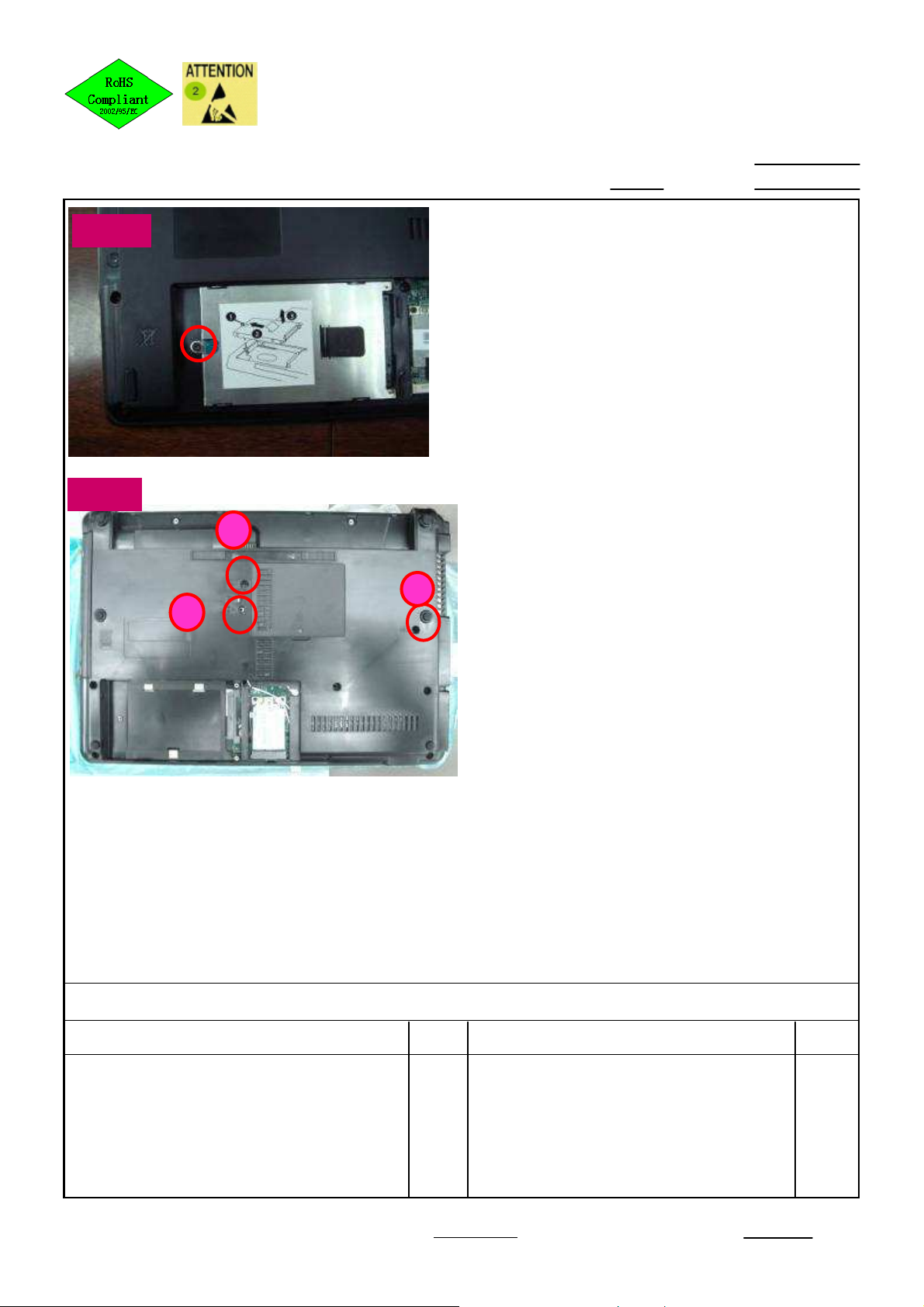
Disassemble HDD& Loosen screws
1. Loosen screws of HDD*1.(Fig.1)
Torsion:2.0 ± 0.2 kgf.cm;
Screws can't be stripped.
2. Loosen screws of ODD & K/B * 3 (Fig.2)
Torsion:2.0 ± 0.2 kgf.cm;
Screws can't be stripped.
3. Pull the puller and to Disassemble HDD.
(Fig.1)
1
3
2
1.00
2(1/1)
2009/05/18
Point for attention:
Fixture list(Fixture standard)
Automatic crossing screw driver
If finding some defects, notice the gaffer and assistant
:
::
Qty
1
Tabulator:_________
Zhang Ying
Fixture list(Fixture standard)
Issuing department:
Qty
IE
Page 6
Working Instruction
Document No. : SOP VV09 FA DIS-ASS’Y Station :
Name : Ver. : Date :
15”
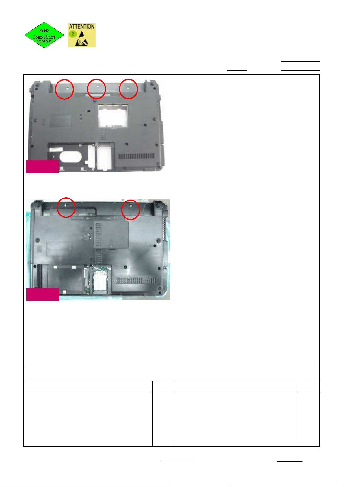
Loosen screws
1. Loosen screws (6052B0096201) of SW
cover .
14” Loosen screws *2,
15” Loosen screws *3
Torsion:2.0 ± 0.2 kgf.cm;
Screws can't be stripped.
1.00
3(1/2)
2009/05/18
14”
Point for attention:
Fixture list(Fixture standard)
Automatic crossing screw driver 1
If finding some defects, notice the gaffer and assistant
:
::
Qty
Tabulator:_________
Fixture list(Fixture standard)
Zhang Ying
Issuing department:
Qty
IE
Page 7
Working Instruction
Document No. : SOP VV09 FA DIS-ASS’Y Station :
Name : Ver. : Date :
1
14”
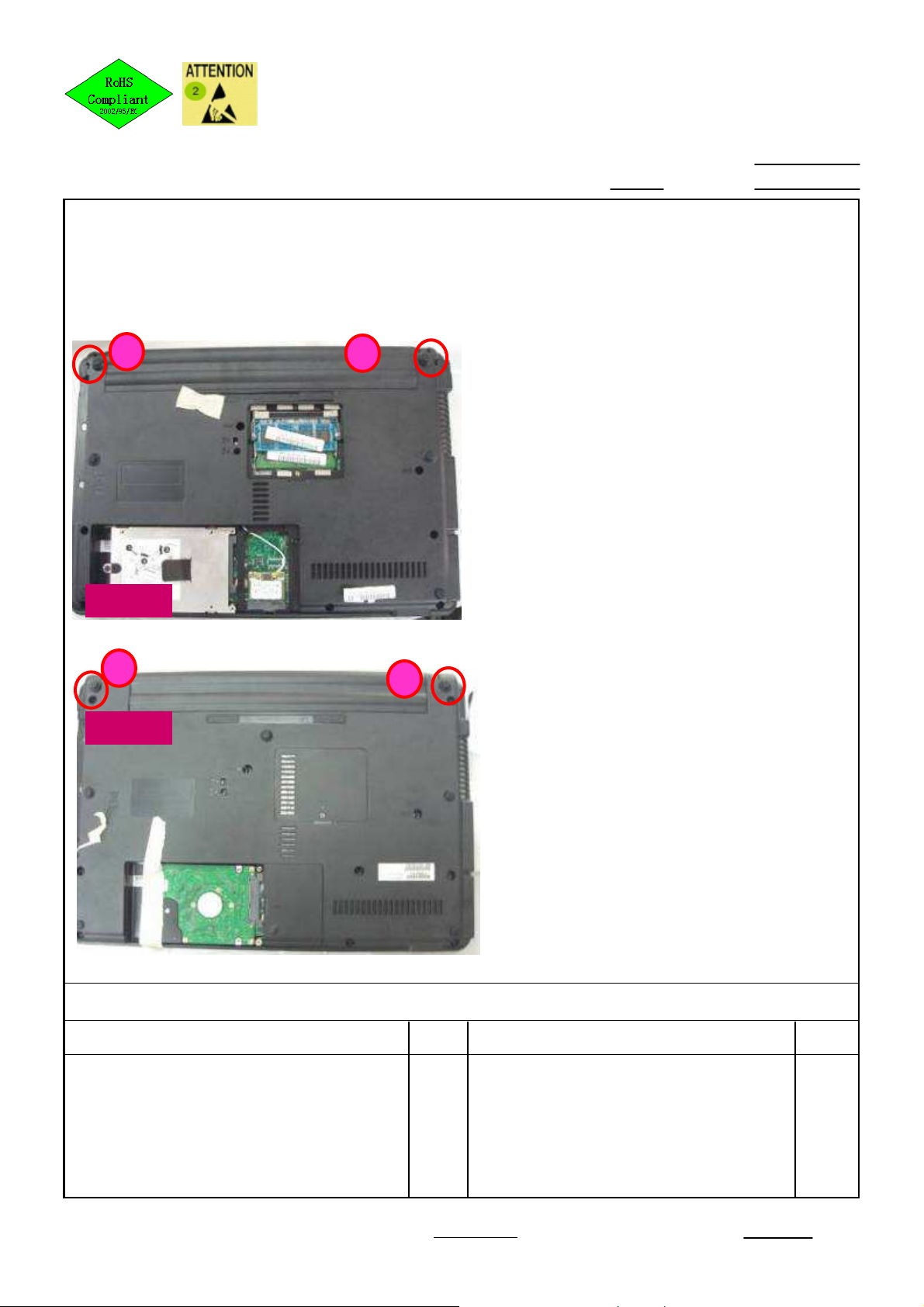
Loosen screws
1. Loosen screws (6052B0111701 ) *2
Torsion:2.0 ± 0.2 Kgf.cm
Screws can't be stripped or dropped
into machine.
2
1.00
3 (2/2)
2009/05/18
1
15”
Point for attention:
Fixture list(Fixture standard)
Automatic crossing screw driver 1
If finding some defects, notice the gaffer and assistant
:
::
2
Qty
Fixture list(Fixture standard)
Qty
Tabulator:_________
Zhang Ying
Issuing department:
IE
Page 8
Working Instruction
Document No. : SOP VV09 FA DIS-ASS’Y Station :
Name : Ver. : Date :
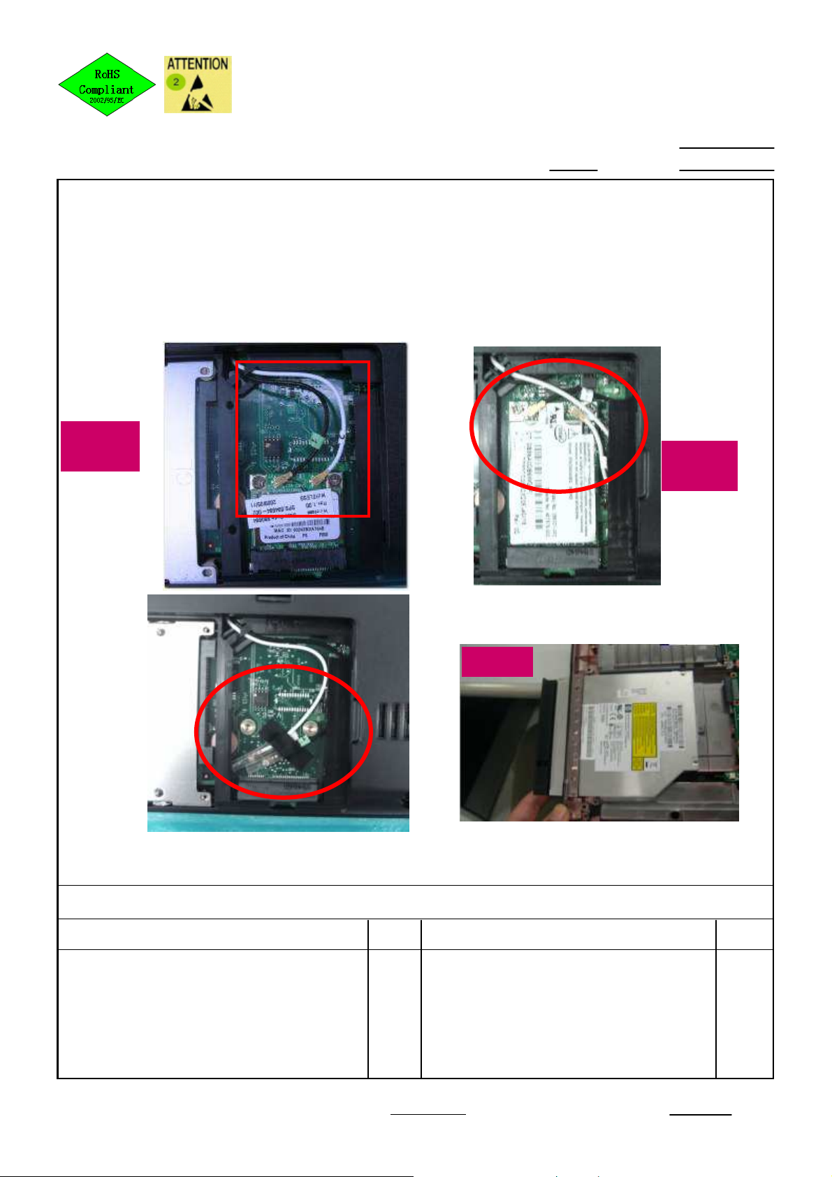
1. Disassemble Antenna cable from WLAN CARD。
2. Take out ODD.(Fig.1)
Half
Card
Disassemble Antenna cable & ODD
1.00
4(1/1)
2009/05/18
Long
card
Without
WLAN
CARD
Point for attention:
Fixture list(Fixture standard)
If finding some defects, notice the gaffer and assistant
:
::
Qty
Fig.1
Fixture list(Fixture standard)
Qty
Tabulator:_________
Zhang Ying
Issuing department:
IE
Page 9
Working Instruction
Document No. : SOP VV09 FA DIS-ASS’Y Station :
Name : Ver. : Date :
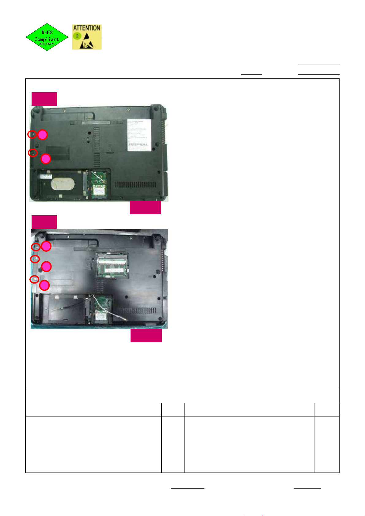
14 “
1
2
15 “
Loosen screws of ODD
2
1. Loosen screws (6052B0097001) of ODD。
14” Loosen screws *2,
15” Loosen screws *3,
Loosen screws with the sequence as figures
showing
Torsion:2.0 ± 0.2 Kgf.cm
Screws can't be stripped or dropped into
machine.
Fig.1
5(1/1)
2009/05/181.00
1
2
3
Fig.2
Point for attention:
Fixture list(Fixture standard)
Automatic crossing screw driver 1
If finding some defects, notice the gaffer and assistant
:
::
Qty
Fixture list(Fixture standard)
Qty
Tabulator:_________
Zhang Ying
Issuing department:
IE
Page 10
Working Instruction
Document No. : SOP VV09 FA DIS-ASS’Y Station :
Name : Ver. : Date :
1
2
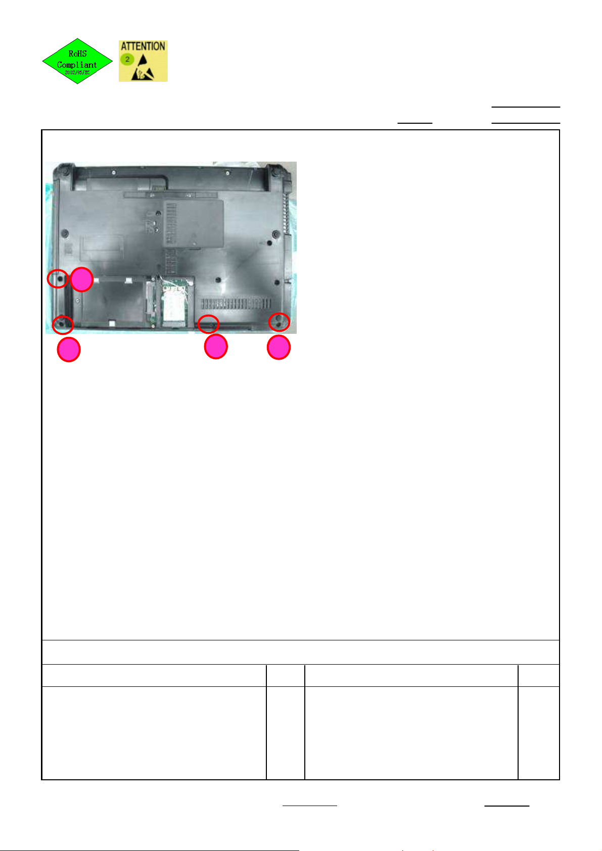
Loosen screws of BTCB
3
1. Loosen screws of BTCB
(6052A0021901 ) * 4
Torsion:2.0 ± 0.2 Kgf.cm
Screws can't be stripped or
dropped into machine.
2. Turn over the machine in the
surface .
4
6(1/1)
2009/05/181.00
Point for attention:
Fixture list(Fixture standard)
Automatic hexagonal screw driver 1
If finding some defects, notice the gaffer and assistant
:
::
Qty
Tabulator:_________
Fixture list(Fixture standard)
Zhang Ying
Issuing department:
Qty
IE
Page 11

Working Instruction
Document No. : SOP VV09 FA DIS-ASS’Y Station :
Name : Ver. : Date :
Fig.1
②
②
②②
Disassemble SW/C
①
①
①①
②
②
②②
1. Disassemble SW/C , Fig.1 g.1
14” : 6070B0350501
15” : 6070B0351101
Sequence:123
2. Turn over the K/B , Fig.2
3
7(1/1)
2009/05/181.00
Fig.2
Point for attention:
Fixture list(Fixture standard)
If finding some defects, notice the gaffer and assistant
:
::
Qty
Fixture list(Fixture standard)
Qty
Tabulator:_________
Zhang Ying
Issuing department:
IE
Page 12

Working Instruction
Document No. : SOP VV09 FA DIS-ASS’Y Station :
Name : Ver. : Date :
Fig.1
Disassemble SW/C&K/B FFC
1. Loosen Lock piece, take out K/B FFC from
MB CNTR. Fig.1
2. Disassemble SW/C&K/B .
1.00
8(1/1)
2009/05/18
Point for attention:
Fixture list(Fixture standard)
If finding some defects, notice the gaffer and assistant
:
::
Qty
Tabulator:_________
Zhang Ying
Fixture list(Fixture standard)
Issuing department:
Qty
IE
Page 13

Working Instruction
Document No. : SOP VV09 FA DIS-ASS’Y Station :
Name : Ver. : Date :
14”
Loosen screws ,,,,Disassemble Speaker
1. Disassemble Speaker CNTR.(Fig.4)
2. Loosen screws of Speaker
(6039B0031401) 。
14” : 6052A0004501 * 3, Fig.1
15” : 6052A0004501 * 2, Fig.2
15” : 6052A0003501 * 1, Fig.3
Torsion:2.0 ± 0.2 Kgf.cm
Screws can't be stripped or dropped into
machine.
9(1/1)
2009/05/181.00
Fig.4
1
Fig.1
15”
1
Point for attention:
Fixture list(Fixture standard)
If finding some defects, notice the gaffer and assistant
:
::
2
Fig.2
2
3
Qty
3
Fixture list(Fixture standard)
Fig.3
Qty
Automatic crossing screw driver 1
Tabulator:_________
Zhang Ying
Issuing department:
IE
Page 14

Working Instruction
Document No. : SOP VV09 FA DIS-ASS’Y Station :
Name : Ver. : Date :
Disassemble LCM Cable
1. Disassemble LCM Cable CNTR。
2. Disassemble Camera CNTR。
15’
Fig.1
图一
10(1/1)
2009/05/181.00
Fig.2
图二
14’
Point for attention:
Fixture list(Fixture standard)
If finding some defects, notice the gaffer and assistant
:
::
Qty
Fig.3
图三
Fixture list(Fixture standard)
Qty
Tabulator:_________
Zhang Ying
Issuing department:
IE
Page 15

Working Instruction
Document No. : SOP VV09 FA DIS-ASS’Y Station :
Name : Ver. : Date :
Fig.1
Disassemble Antenna Cable, Camera Cable
1.Pull out Antenna cable along the slot of BTCB. (Fig.1).
2.Disassemble Antenna Cable ,Camera Cable.(Fig.2)
11(1/1)
2009/05/181.00
Point for attention:
Fixture list(Fixture standard)
If finding some defects, notice the gaffer and assistant
:
::
Fig.2
Qty
Fixture list(Fixture standard)
Qty
Tabulator:_________
Zhang Ying
Issuing department:
IE
Page 16

Working Instruction
Document No. : SOP VV09 FA DIS-ASS’Y Station :
Name : Ver. : Date :
1
Loosen screws of LCM ( For 14”)
1. Loosen screws of LCM
(6052B0098201 ) * 4。
Torsion:3.5 ± 0.2 Kgf.cm
Screws can't be stripped or dropped into
machine.
2
12(1/2)
2009/05/181.00
14’
Point for attention:
Fixture list(Fixture standard)
Automatic hexagonal screw driver 1
If finding some defects, notice the gaffer and assistant
:
::
Qty
3
4
Fixture list(Fixture standard)
Qty
Tabulator:_________
Zhang Ying
Issuing department:
IE
Page 17

Working Instruction
Document No. : SOP VV09 FA DIS-ASS’Y Station :
Name : Ver. : Date :
1
Loosen screws of LCM( For 15”)
1. Loosen screws of LCM
(6052B0098201 ) * 4。
Torsion:3.5 ± 0.2 Kgf.cm
Screws can't be stripped or dropped into
machine.
2
3
12(2/2)
2009/05/181.00
15’
Point for attention:
Fixture list(Fixture standard)
Automatic hexagonal screw driver 1
If finding some defects, notice the gaffer and assistant
:
::
Qty
4
Fixture list(Fixture standard)
Qty
Tabulator:_________
Zhang Ying
Issuing department:
IE
Page 18

Working Instruction
Document No. : SOP VV09 FA DIS-ASS’Y Station :
Name : Ver. : Date :
15”
14”
1
Loosen screws
1
2
1. Loosen screws of TPCB.
(6052B0098201) * 2 (for 14”);
(6052B0098201) * 2 (for 15”)
Torsion:2.0 ± 0.2 Kgf.cm
Screws can't be stripped or dropped into
machine.
2. Turn over the machine in the surface .
3. Loosen screws of BTCB(6052A0021901 ) *2。
Torsion:2.0 ± 0.2 Kgf.cm
Screws can't be stripped or dropped into
machine.
13(1/1)
2009/05/181.00
2
Point for attention:
Fixture list(Fixture standard)
Automatic hexagonal screw driver 1
If finding some defects, notice the gaffer and assistant
:
::
Qty
4
Fixture list(Fixture standard)
3
Qty
Tabulator:_________
Zhang Ying
Issuing department:
IE
Page 19

Working Instruction
Document No. : SOP VV09 FA DIS-ASS’Y Station :
Name : Ver. : Date :
Fig.1
Fig.2
Disassemble TPCB
1. Disassemble TPCB (Fig.1)。
2. Disassemble TPCB TOUCH PAD FFC
from M/B(Fig.2)。
14(1/1)
2009/05/181.00
Point for attention:
Fixture list(Fixture standard)
If finding some defects, notice the gaffer and assistant
:
::
Qty
Tabulator:_________
Zhang Ying
Fixture list(Fixture standard)
Issuing department:
Qty
IE
Page 20

Working Instruction
Document No. : SOP VV09 FA DIS-ASS’Y Station :
Name : Ver. : Date :
Fig.1
Fig.2
Disassemble Bluetooth
1
2
1. Loosen screws of Bluetooth
(6052A0004501) *2
2. Disassemble Bluetooth Cable from MB CNTR
(Fig.2)
3. Disassemble Cable and Bluetooth
Torsion:1.0 ± 0.2 Kgf.cm
Screws can't be stripped or dropped into
machine.
1.00
15(1/1)
2009/05/18
Point for attention:
Fixture list(Fixture standard)
Automatic crossing screw driver 1
If finding some defects, notice the gaffer and assistant
:
::
Qty
Tabulator:_________
Fixture list(Fixture standard)
Zhang Ying
Issuing department:
Qty
IE
Page 21

Working Instruction
Document No. : SOP VV09 FA DIS-ASS’Y Station :
Name : Ver. : Date :
Loosen screws of M/B and ODD extension board
14”
Fig.1
15”
1. Loosen screws of M/B
(6052A0034902) * 1 (Fig.1)。
Torsion:2.0 ± 0.2 Kgf.cm
Screws can't be stripped or dropped into
machine.
2. Disassemble RJ11 Cable (Fig.1).
The machine have not Modem, which
disassemble the False shell
(6051B0409801) . (Fig.3).
FOR 15” ONLY
3. Loosen screws of ODD extension board
(6052A0034902) *2。
Torsion:2.0 ± 0.2 Kgf.cm
Screws can't be stripped or dropped into
machine.
16(1/1)
2009/05/181.00
Point for attention:
Fixture list(Fixture standard)
If finding some defects, notice the gaffer and assistant
:
::
ODD/B
screws
M/B
screws
Fig.2
Qty
False
shell
Fixture list(Fixture standard)
Fig.3
Qty
Automatic crossing screw driver 1
Tabulator:_________
Zhang Ying
Issuing department:
IE
Page 22

Working Instruction
Document No. : SOP VV09 FA DIS-ASS’Y Station :
Name : Ver. : Date :
Fig.1
Disassemble FAN Cable and M/B
1. Disassemble FAN Cable CNTR , Fig.2,
Fig.3。
2. Take out M/B 。
Disassemble above the M/B first by right
hand;
Please don't touch LED light part while
taking and fetching M/B.
17(1/1)
2009/05/181.00
Fig.2
Point for attention:
Fixture list(Fixture standard)
Automatic crossing screw driver 1
If finding some defects, notice the gaffer and assistant
:
::
Qty
Tabulator:_________
Fixture list(Fixture standard)
Zhang Ying
Fig.3
Issuing department:
Qty
IE
Page 23

Working Instruction
Document No. : SOP VV09 FA DIS-ASS’Y Station :
Name : Ver. : Date :
Fig.1
Disassemble FAN
1. Loosen screws of FAN (6052A0003501) * 2。
Torsion:2.0 ± 0.2 Kgf.cm
Screws can't be stripped .
2. Take down FAN (6033B0019801).
18(1/1)
2009/05/181.00
Point for attention:
Fixture list(Fixture standard)
Automatic crossing screw driver 1
If finding some defects, notice the gaffer and assistant
:
::
Qty
Tabulator:_________
Fixture list(Fixture standard)
Zhang Ying
Issuing department:
Qty
IE
Page 24

Working Instruction
Document No. : SOP VV09 FA DIS-ASS’Y Station :
Name : Ver. : Date :
Disassemble WLAN and Loosen screws
Intel discrete
4
2
3
1
For platform without WLAN, needn’t to
disassemble WLAN
1. Put MB on supporting fixture.
2. Loosen two screws (6052A0034902) and take
down WLAN. (Fig.1)
3. Loosen screws of thermal elastic*2
Torsion:1.5 ± 0.2 Kgf.cm
Screws can't be stripped .
AMD discrete
4
19(1/2)
2009/05/181.00
2
1
3
Point for attention:
Fixture list(Fixture standard)
Automatic crossing screw driver 1
If finding some defects, notice the gaffer and assistant
:
::
Qty
Fixture list(Fixture standard)
Qty
VV09 M/B B side supporting fixture 1
Tabulator:_________
Zhang Ying
Issuing department:
IE
Page 25

Working Instruction
Document No. : SOP VV09 FA DIS-ASS’Y Station :
Name : Ver. : Date :
Fig.1
GOOD
Assemble Wireless Card
1. Pick and place 1PCS Wireless Card every time, only
hold the two sides of RAM with figures(Fig.1)
Wear the gloves, pay attention to ESD.
Forbid pressing one side of Wireless Card and picking
it on the other side(Fig.2 and Fig.3)
Forbid holding the two surfaces of Wireless Card(Fig.4)
Forbid fetching more than two Wireless Card at the
same time(Fig.5)
Several Wireless Card can’t touch each other,
especially the Golden figures(Fig.6)
1.00
Fig.2
press one side
of Wireless
Card and
picking it on
the other side
Fetch more
than two
Wireless Card
at the same
time
Fig.5
NG
19(2/2)
2009/5/18
Fig.3
NG
Fig.4
NG
Point for attention:
Fixture list(Fixture standard)
If finding some defects, notice the gaffer and assistant
:
::
hold the two
surfaces of
Wireless Card
Qty
Fig.6
Several Wireless
Card can’t touch
each other,
especially the
Golden figures
Fixture list(Fixture standard)
Qty
Tabulator:_________
Zhang Ying
Issuing department:
IE
Page 26

Working Instruction
Document No. : SOP VV09 FA DIS-ASS’Y Station :
Name : Ver. : Date :
Fig.1
Fig.2
Take down RAM and 15“ ODD extension board
1. Put MB on supporting fixture.
2. Take down DDR 。(IF have two , need
disassemble the two DDR)
3.Tear the tape of acetic acid
(6054A0076201 ) *1 and gasket
(6054B0430101 )*1 from RJ11 Cable .
(Fig.2)
FOR 15” ONLY
tape of acetic acid
4. Take down 15“ ODD extension board
, Fig.3。
20(1/1)
2009/05/181.00
gasket
Fig.3
Point for attention:
Fixture list(Fixture standard)
Automatic crossing screw driver 1
If finding some defects, notice the gaffer and assistant
:
::
Qty
Fixture list(Fixture standard)
Qty
VV09 M/B B side supporting fixture 1
Tabulator:_________
Zhang Ying
Issuing department:
IE
Page 27

Working Instruction
Document No. : SOP VV09 FA DIS-ASS’Y Station :
Name : Ver. : Date :
Loosen screws and take down THERMAL
1. Put MB on supporting fixture.
1
4
2. Loosen four screws of Thermal 。
Torsion:1.5 ± 0.2 Kgf.cm
Screws can't be stripped .
2
3
Don’t hold the Copper Pipe of Thermal.
3. Take down CPU Thermal.
AMD DIS
1
4
THERMAL MODULE,AMD,DISCRETE6043B0065101
THERMAL MODULE,AMD,UMA6043B0065201
THERMAL MODULE,INTEL,UMA6043B0065301
THERMAL MODULE,INTEL,DISCRETE6043B0065401
22(1/2)
2009/05/181.00
3
2
AMD UMA
Point for attention:
Fixture list(Fixture standard)
Automatic crossing screw driver 1
VV09 M/B B side supporting fixture 1
If finding some defects, notice the gaffer and assistant
:
::
Qty
Fixture list(Fixture standard)
Qty
Tabulator:_________
Zhang Ying
Issuing department:
IE
Page 28

Working Instruction
Document No. : SOP VV09 FA DIS-ASS’Y Station :
Name : Ver. : Date :
Loosen screws and take down THERMAL
1. Put MB on supporting fixture.
2. Loosen four screws of Thermal 。
Torsion:1.5 ± 0.2 Kgf.cm
Screws can't be stripped .
2
3
Don’t hold the Copper Pipe of Thermal.
3. Take down CPU Thermal.
1
4
Intel UMA
THERMAL MODULE,AMD,DISCRETE6043B0065101
THERMAL MODULE,AMD,UMA6043B0065201
THERMAL MODULE,INTEL,UMA6043B0065301
22(2/2)
2009/05/181.00
2
4
3
1
Intel DIS
Point for attention:
Fixture list(Fixture standard)
Automatic crossing screw driver 1
If finding some defects, notice the gaffer and assistant
:
::
Qty
THERMAL MODULE,INTEL,DISCRETE6043B0065401
Fixture list(Fixture standard)
Qty
VV09 M/B B side supporting fixture 1
Tabulator:_________
Zhang Ying
Issuing department:
IE
Page 29

Working Instruction
Document No. : SOP VV09 FA DIS-ASS’Y Station :
Name : Ver. : Date :
Fig.1
图一
图一
图一图一
Fig.2
OPEN Status
Take out CPU
1. Put MB on supporting fixture.
2. Take down CPU from CPU SOCKET
with suck pen.
(take down it in counter clockwise)
23(1/1)
2009/05/181.00
CLOSED Status
Point for attention:
Fixture list(Fixture standard)
Flat screw driver 1
suck pen 1
VV09 M/B B side supporting fixture 1
If finding some defects, notice the gaffer and assistant
:
::
Qty
Tabulator:_________
Fixture list(Fixture standard)
Zhang Ying
Issuing department:
Qty
IE
Page 30

Working Instruction
Document No. : SOP VV09 FA DIS-ASS’Y Station :
Name : Ver. : Date :
Fig.1
2
Take down MODEM and RJ11 cable
1
1. Put M/B on supporting fixture
2. Loosen screws (6052A0034902) * 2
and take down MODEM from M/B ,
(Fig1,Fig2)
3. Take down RJ11 CABLE
(6017B0119501 ) from Modem. (Fig.3)
Torsion:1.5 ± 0.2 Kgf.cm
Screws can't be stripped
1.00
24(1/1)
2009/05/18
MODEM
1
2
图图图图二二二二
Fig.2
Point for attention:
Fixture list(Fixture standard)
Automatic crossing screw driver 1
VV09 M/B B side supporting fixture 1
If finding some defects, notice the gaffer and assistant
:
::
Qty
Fig.2
图三
图三
图三图三
Fixture list(Fixture standard)
Qty
Tabulator:_________
Zhang Ying
Issuing department:
IE
Page 31

Working Instruction
Document No. : SOP VV09 FA DIS-ASS’Y Station :
Name : Ver. : Date :
LCM CNTR
LCM CNTR
LCM CNTRLCM CNTR
Visual inspect M/B
Mylar
1. Cosmetic inspecting。
Don’t touch the LED lamp fetching M/B 。
Inspect the cable manager dropped or not 。
Inspect Audio Jack iron part coming off or not。
Inspect LCM CNTR PIN askew and cracked or
not 。
25(1/1)
2009/05/181.00
MIC Jack
MIC Jack
Audio Jack
Audio Jack
Audio JackAudio Jack
Point for attention:
Fixture list(Fixture standard)
MIC JackMIC Jack
If finding some defects, notice the gaffer and assistant
:
::
Qty
Tabulator:_________
Zhang Ying
Fixture list(Fixture standard)
Issuing department:
Qty
IE
 Loading...