

Page 1

Maintenance and Service Guide
HP Engage One Retail System, Model 141
HP Engage One Retail System, Model 143
HP Engage One Retail System, Model 145
Page 2

© Copyright 2017, 2018 HP Development
Company, L.P.
ENERGY STAR® is a registered mark owned by
the U.S. government. Intel, Celeron, and Core
are trademarks of Intel Corporation in the
United States and/or other countries. Windows
is either a registered trademark or trademark
of Microsoft Corporation in the United States
and/or other countries.
The information contained herein is subject to
change without notice. The only warranties for
HP products and services are set forth in the
express warranty statements accompanying
such products and services. Nothing herein
should be construed as constituting an
additional warranty. HP shall not be liable for
technical or editorial errors or omissions
contained herein.
Second Edition: August 2018
First Edition: August 2017
Document Part Number: 925670-002
Product notice
This guide describes features that are common
to most models. Some features may not be
available on your computer.
Software terms
By installing, copying, downloading, or
otherwise using any software product
preinstalled on this computer, you agree to be
bound by the terms of the HP End User License
Agreement (EULA). If you do not accept these
license terms, your sole remedy is to return the
entire unused product (hardware and software)
within 14 days for a full refund subject to the
refund policy of your seller.
For any further information or to request a full
refund of the price of the computer, please
contact your seller.
Page 3

Safety warning notice
WARNING! To reduce the possibility of heat-related injuries or of overheating the device, do not place
the device directly on your lap or obstruct the device air vents. Use the device only on a hard, at surface. Do
not allow another hard surface, such as an adjoining optional printer, or a soft surface, such as pillows or rugs
or clothing, to block airow. Also, do not allow the AC adapter to contact the skin or a soft surface, such as
pillows or rugs or clothing, during operation. The device and the AC adapter comply with the user-accessible
surface temperature limits dened by the International Standard for Safety of Information Technology
Equipment (IEC 60950-1).
iii
Page 4

iv Safety warning notice
Page 5

Table of contents
1 Product overview .......................................................................................................................................... 1
Standard features .................................................................................................................................................. 1
Integrated features ................................................................................................................................................ 3
Stand options ......................................................................................................................................................... 4
HP Engage One Basic I/O Connectivity Base components .................................................................................... 4
HP Engage One Advanced I/O Connectivity Base components ............................................................................. 5
Connecting an AC adapter to power ...................................................................................................................... 6
Locating the Engage One power button ................................................................................................................ 7
Locating the I/O connectivity base power button ................................................................................................. 7
Adjusting the Engage One head unit ..................................................................................................................... 8
Engage One serial number location ...................................................................................................................... 9
I/O connectivity base serial number location ........................................................................................................ 9
2 Illustrated parts catalog .............................................................................................................................. 10
Computer major components .............................................................................................................................. 10
Peripherals ........................................................................................................................................................... 12
Cables and adapters ............................................................................................................................................ 13
3 Routine care, SATA drive guidelines, and disassembly preparation .................................................................. 14
Computer operating guidelines and routine care ............................................................................................... 14
Touch screen maintenance .................................................................................................................................. 14
MSR maintenance ................................................................................................................................................ 15
Service considerations ......................................................................................................................................... 15
Tools and software requirements ..................................................................................................... 15
Screws ............................................................................................................................................... 15
Cables and connectors ...................................................................................................................... 15
Lithium coin cell battery .................................................................................................................... 15
Electrostatic discharge information .................................................................................................................... 16
Generating static ............................................................................................................................... 16
Preventing electrostatic damage to equipment ............................................................................... 16
Personal grounding methods and equipment .................................................................................. 17
Grounding the work area ................................................................................................................... 17
Recommended materials and equipment ........................................................................................ 18
4 Removal and replacement procedures ........................................................................................................... 19
Preparation for disassembly ............................................................................................................................... 19
v
Page 6

Attaching an I/O connectivity base to the Engage One ....................................................................................... 20
Connecting a standalone I/O connectivity base to the Engage One ................................................................... 22
Conguring the I/O connectivity base’s powered serial ports ............................................................................ 22
Connecting a standalone optional ngerprint reader to the I/O connectivity base ........................................... 24
Attaching an optional ngerprint reader to the I/O connectivity base ............................................................... 25
Removing and attaching the Engage One head unit to the stand ...................................................................... 27
Mounting the Engage One head unit to a wall .................................................................................................... 28
Mounting the Engage One to a counter top ........................................................................................................ 30
Installing a security cable on the I/O connectivity base ..................................................................................... 32
Installing a security cable on the Engage One column ....................................................................................... 33
Installing a security screw on the Engage One head unit and stand .................................................................. 34
Installing a security screw on the Engage One head unit and VESA mount ....................................................... 35
Removing and replacing the column printer ....................................................................................................... 35
Removing the display panel ................................................................................................................................ 41
System board components .................................................................................................................................. 42
Installing a 2 x 20 customer-facing display (CFD) ............................................................................................... 43
Memory modules ................................................................................................................................................. 45
DDR4-SDRAM SODIMMs .................................................................................................................... 45
Removing a SODIMM ......................................................................................................................... 45
Removing and installing an M.2 solid-state drive (SSD) ..................................................................................... 48
Removing the WLAN module ............................................................................................................................... 49
Removing the heat sink ....................................................................................................................................... 51
Removing the fan assembly ................................................................................................................................ 52
Removing the speakers ....................................................................................................................................... 53
Removing the power button board ..................................................................................................................... 54
Removing the MSR (Magnetic Stripe Reader) ...................................................................................................... 55
MSR conguration ............................................................................................................................. 56
Removing the MSR LED board ............................................................................................................................. 58
Removing the system board ................................................................................................................................ 59
System board callouts ....................................................................................................................... 61
Removing the antennas ....................................................................................................................................... 62
5 Using the column printer .............................................................................................................................. 63
Standard features ................................................................................................................................................ 63
Printing features .................................................................................................................................................. 63
When to change the receipt paper ...................................................................................................................... 64
Loading the printer receipt paper ........................................................................................................................ 64
Thermal paper specications .............................................................................................................................. 65
Qualied paper grades ........................................................................................................................................ 65
Troubleshooting the printer ................................................................................................................................ 66
Printer tone and green LED ............................................................................................................... 67
vi
Page 7

Printing issues ................................................................................................................................... 67
Printer does not function .................................................................................................................. 68
Latch failsafe ..................................................................................................................................... 69
Cleaning the printer ............................................................................................................................................. 69
6 Cable routing congurations ........................................................................................................................ 70
Cable matrix for Engage One with integrated column printer and basic I/O connectivity base ......................... 70
Cable matrix for Engage One with integrated column printer and advanced I/O connectivity base ................. 71
Cable matrix for Engage One without I/O connectivity base .............................................................................. 72
Cable matrix for Engage One with I/O connectivity base .................................................................................... 73
Cable matrix for Engage One with basic I/O connectivity base and standalone printer .................................... 74
Cable matrix for Engage One with advanced I/O connectivity base and standalone printer ............................. 75
7 Conguring the software .............................................................................................................................. 76
Touch screen calibration for Windows 10 Professional and Windows 10 IoT Enterprise for Retail .................. 76
Conguring optional HP integrated peripheral modules .................................................................................... 76
8 Computer Setup (F10) Utility ........................................................................................................................ 77
Computer Setup (F10) Utilities ............................................................................................................................ 77
Using Computer Setup (F10) Utilities ................................................................................................ 77
Computer Setup–Main ....................................................................................................................... 79
Computer Setup—Security ............................................................................................................... 81
Computer Setup—Advanced ............................................................................................................. 83
Recovering the Conguration Settings ............................................................................................................... 87
9 POST error messages and diagnostic front panel LEDs and audible codes ......................................................... 88
POST numeric codes and text messages ............................................................................................................. 88
Interpreting system validation diagnostic front panel LEDs and audible codes ................................................ 93
10 Password security and resetting CMOS ........................................................................................................ 95
Resetting the password jumper .......................................................................................................................... 95
Changing a Setup or Power-On password ........................................................................................................... 96
Deleting a Setup or Power-On password ............................................................................................................ 97
Clearing and resetting the CMOS ......................................................................................................................... 97
11 Using HP PC Hardware Diagnostics (UEFI) ..................................................................................................... 99
Downloading HP PC Hardware Diagnostics (UEFI) to a USB device .................................................................... 99
Using Remote HP PC Hardware Diagnostics (UEFI) settings (select products only) ........................................ 100
Customizing Remote HP PC Hardware Diagnostics (UEFI) settings ............................................... 100
vii
Page 8

12 Troubleshooting without diagnostics ........................................................................................................ 101
Safety and comfort ............................................................................................................................................ 101
Before you call for technical support ................................................................................................................ 101
Helpful hints ...................................................................................................................................................... 102
Solving retail system-specic problems ........................................................................................................... 103
Solving general problems .................................................................................................................................. 104
Solving printer problems ................................................................................................................................... 108
Solving hardware installation problems ........................................................................................................... 109
Solving network problems ................................................................................................................................ 110
Solving memory problems ................................................................................................................................ 112
Solving USB ash drive problems ..................................................................................................................... 114
Solving Internet access problems ..................................................................................................................... 114
Solving software problems ............................................................................................................................... 116
13 System backup and recovery ..................................................................................................................... 117
Backing up, restoring, and recovering in Windows 10 ...................................................................................... 117
Creating recovery media and backups ............................................................................................ 117
Creating HP Recovery media (select products only) .................................................... 117
Using Windows tools ....................................................................................................................... 119
Restore and recovery ...................................................................................................................... 119
Recovering using HP Recovery Manager ...................................................................... 119
What you need to know before you get started ........................................ 119
Using the HP Recovery partition (select products only) ............................ 120
Using HP Recovery media to recover ......................................................... 120
Changing the computer boot order ............................................................ 121
Removing the HP Recovery partition (select products only) ..................... 121
Appendix A Power cord set requirements ....................................................................................................... 122
General requirements ........................................................................................................................................ 122
Japanese power cord requirements .................................................................................................................. 122
Country-specic requirements .......................................................................................................................... 123
Appendix B Statement of memory volatility ................................................................................................... 124
Nonvolatile memory usage ............................................................................................................................... 126
Questions and answers ..................................................................................................................................... 128
Using HP Sure Start (select models only) .......................................................................................................... 129
Appendix C Specications ............................................................................................................................. 130
Index ........................................................................................................................................................... 132
viii
Page 9
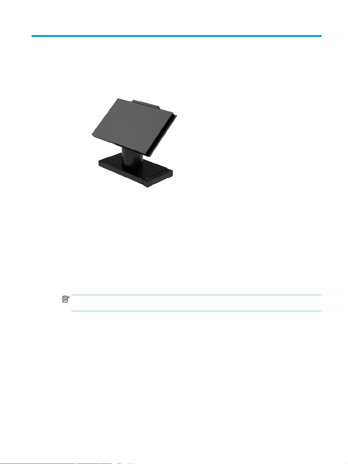
1 Product overview
Standard features
The HP Engage One Retail System is designed for long-term deployment within general retail, hospitality, and
other markets. It includes the following features:
●
Integrated All-in-One (AiO) form factor
●
14-inch diagonal display panel (wide-aspect ratio); FHD 1920 x 1080 resolution, sealed and chemically
hardened, anti-glare; anti-smudge
●
Model 141: anti-glare WLED SVA 300-nit panel with FHD 1920 x 1080 resolution and an Intel® Celeron®
3965U 2.2 GHz 2M 2133 2C6 processor
●
Model 143: anti-glare WLED UWVA 500-nit panel with FHD 1920 x 1080 resolution and an Intel® Core™
i3 - 7100U 2.40 GHz 3M 2133 2C6 processor
●
Model 145: anti-glare WLED UWVA 500-nit panel with FHD 1920 x 1080 resolution and an Intel® i5 7300U 2.60 GHZ 3MB 2133 2C6 processor
NOTE: Nits is the measure of the typical brightness of the panel as specied, prior to anti-glare
coating.
●
Optional 100 mm x 100 mm VESA mounting bracket
●
Optional counter top mounting bracket
●
Choice of a rotate/tilt stand with a 10° tilt range and 180° swivel capability, or a xed position stand
●
Optional HP peripherals:
–
HP Engage One integrated magnetic strip reader (MSR) (integrated into the head unit as congure
to order)
–
HP Engage One integrated 2 x 20 LCD customer-facing display (CFD), top mount
–
HP Engage One integrated column printer or standalone printer
–
HP Engage One 2D barcode scanner
–
HP Engage One biometric ngerprint reader
Standard features 1
Page 10

●
DDR4 2400 MHz memory with up to 32 GB RAM
●
Operating system choices:
–
Windows® 10 IoT Enterprise 2016 LTSB 64-bit
–
Windows 10 Professional 64-bit
–
FreeDOS 2.0
●
HP Engage One Advanced I/O Connectivity Base (optional)
–
2 powered serial ports (0 V, 5 V, 12 V)
–
(2) 12 V powered USB ports
–
(1) 24 V powered USB port
–
4 USB 3.0 ports
–
1 cash drawer jack
–
1 RJ-45 network jack
–
1 video-out USB Type-C port
●
HP Engage One Basic I/O Connectivity Base (optional)
–
3 powered serial ports (0 V, 5 V, 12 V)
–
4 USB 2.0 ports
–
2 USB 3.0 ports
–
1 cash drawer jack
–
1 RJ-45 network jack
–
1 video out USB Type-C port
●
One internal SD card reader on the computer head unit and one external microSD card reader on the I/O
connectivity base
●
Universal audio jack with CTIA headset support on the I/O connectivity base
●
One M.2 SSD internal drive on the computer head unit
●
ENERGY STAR® compliant
2 Chapter 1 Product overview
Page 11
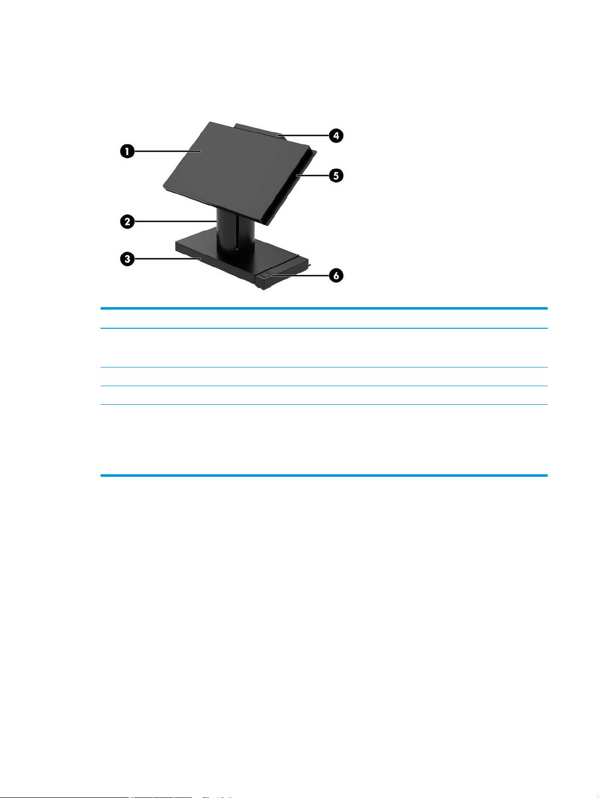
Integrated features
The integrated devices shown below are optional.
Features
(1) 14-inch diagonal display panel (wide-aspect ratio); FHD
1920 x 1080 resolution, sealed and chemically hardened,
anti-glare; anti-smudge
(2) HP Engage One Integrated Column Printer (5) HP Engage One Integrated MSR
(3) Choice of 2 Engage One I/O Connectivity Bases (6) HP Engage One Biometric Fingerprint Reader
Display panel options:
●
Anti-glare WLED SVA 300 nits panel
●
Anti-glare WLED UWVA 500 nits panel
NOTE: Nits is the measure of the typical brightness of the panel as specied, prior to anti-glare coating.
(4) HP Engage One 2 x 20 Customer-facing Display (CFD)
Integrated features 3
Page 12
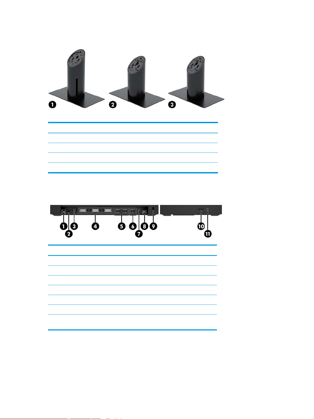
Stand options
Options
(1) HP Engage One Rotate/Tilt Stand with Integrated Column Printer
(2) HP Engage One Rotate/Tilt Stand
(3) HP Engage One Fixed Position Stand
NOTE: The stands are shown on a stability base.
HP Engage One Basic I/O Connectivity Base components
Basic components
(1) Cash drawer jack (7) USB Type-C port
(2) Power connector (8) RJ-45 network jack
(3) USB Type-C power port (9) Security cable slot
(4) Powered serial ports (3) (10) MicroSD card reader
(5) USB 2.0 ports (4) (11) Headset jack
(6) USB 3.0 ports (2)
IMPORTANT: To avoid damage to the computer, DO NOT plug a telephone cable into the cash
drawer jack.
4 Chapter 1 Product overview
Page 13
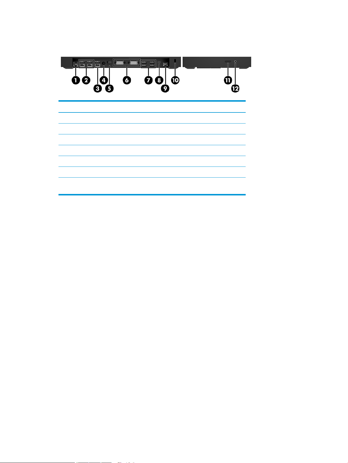
HP Engage One Advanced I/O Connectivity Base components
Advanced components
(1) Cash drawer jack (7) USB 3.0 ports (4)
(2) Powered USB 12 V ports (2) (8) USB Type-C port
(3) Powered USB 24 V port (9) RJ-45 network jack
(4) Power connector (10) Security cable slot
(5) USB Type-C power port (11) MicroSD card reader
(6) Powered serial ports (2) (12) Headset jack
IMPORTANT: To avoid damage to the computer, DO NOT plug a telephone cable into the cash
drawer jack.
HP Engage One Advanced I/O Connectivity Base components 5
Page 14
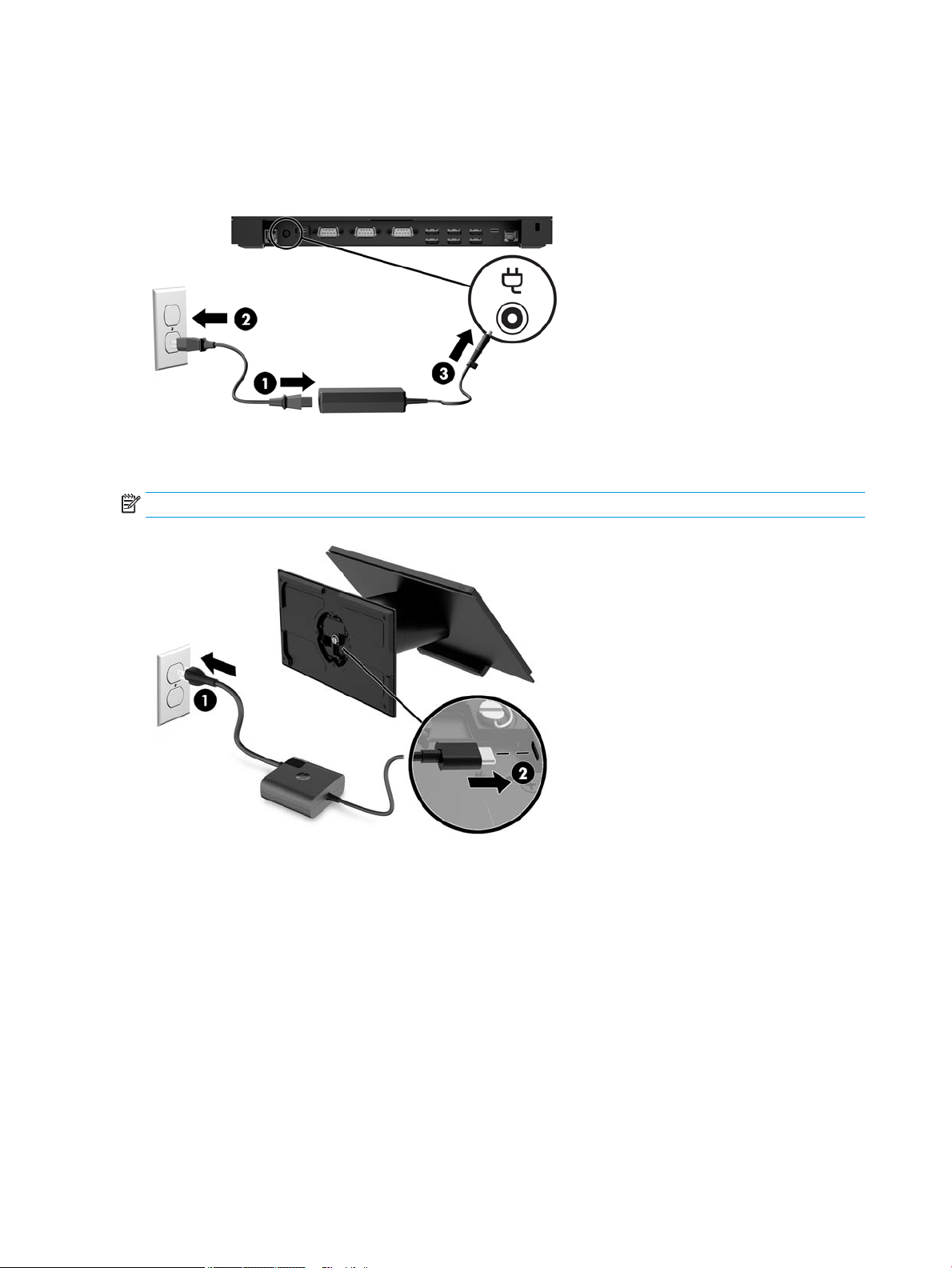
Connecting an AC adapter to power
To connect an AC adapter to the I/O connectivity base, connect one end of the power cord to the AC adapter (1)
and the other end to a grounded AC outlet (2), and then connect the AC adapter to the power connector on the
I/O connectivity base (3).
To connect an AC adapter to the computer when it is not connected to an I/O connectivity base, connect the AC
adapter to a grounded AC outlet (1), and then the connect the power adapter’s USB Type-C connector to the
USB Type-C power port on the underside of the stand or stability base (2).
NOTE: The image below is shown with a stability base.
6 Chapter 1 Product overview
Page 15
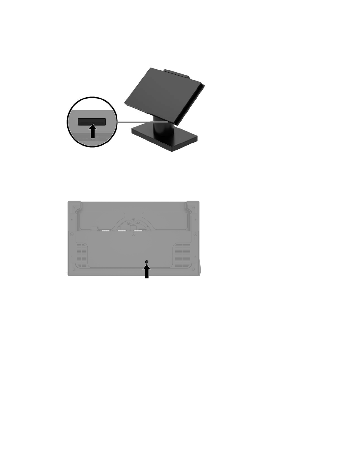
Locating the Engage One power button
The computer power button is located on the bottom right edge of the bezel.
Locating the I/O connectivity base power button
The I/O connectivity base power button is located on the underside of the I/O connectivity base.
The head unit controls the I/O connectivity base. When the head unit is turned o, the I/O connectivity base is
turned o and power is not available from the I/O connectivity base ports. The exception is the I/O
connectivity base’s USB Type-C port that connects to the head unit. That port will remain powered so that it
can continue to communicate with the head unit and allow the I/O connectivity base to turn back on when the
head unit is turned on.
After the system has been turned o, you can press the power button on the underside of the I/O connectivity
base to allow power to be available on the I/O connectivity base ports while the head unit remains turned o.
Locating the Engage One power button 7
Page 16
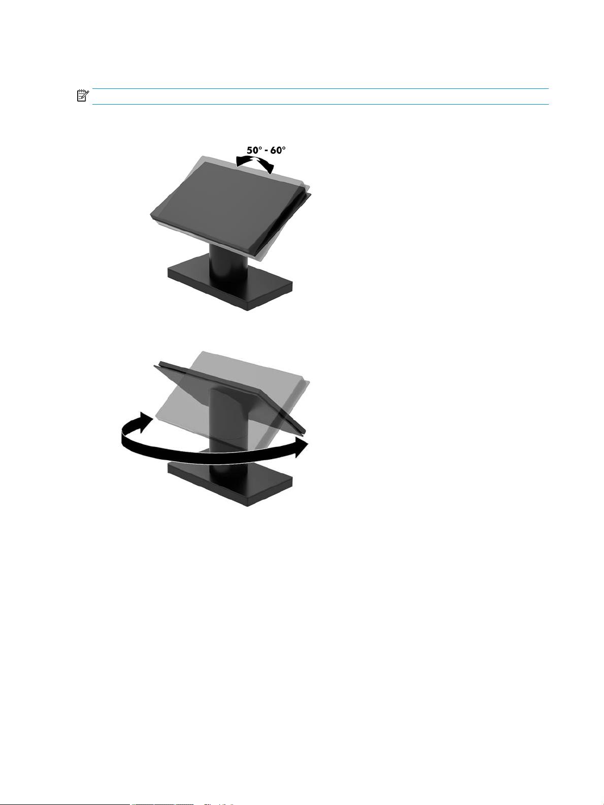
Adjusting the Engage One head unit
NOTE: The tilt and swivel features are only available on performance stands.
You can tilt and swivel the computer head to set it to a comfortable viewing angle. There is a 10° tilt range
that can be set between 50° and 60°.
The computer head unit can be swiveled 180° in either direction.
8 Chapter 1 Product overview
Page 17
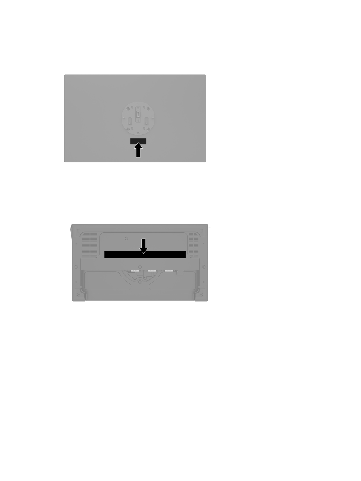
Engage One serial number location
Each computer has a unique serial number and a product ID number that are located on the exterior of the
computer. Keep these numbers available for use when contacting customer service for assistance.
I/O connectivity base serial number location
Each I/O connectivity base has a unique serial number and a product ID number that are located on the
exterior of the I/O connectivity base. Keep these numbers available for use when contacting customer service
for assistance.
Regulatory information is located in the base plate or wall mount. Install the base plate or wall mount back
after disassembly.
Engage One serial number location 9
Page 18
2 Illustrated parts catalog
NOTE: HP continually improves and changes product parts. For complete and current information on
supported parts for your computer, go to http://partsurfer.hp.com, select your country or region, and then
follow the on-screen instructions.
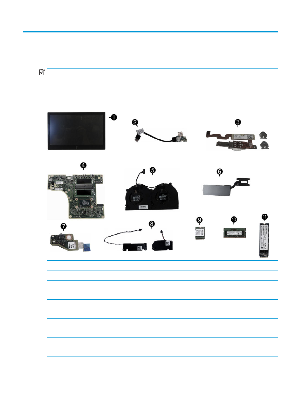
Computer major components
Item Description
(*) Whole unit (not illustrated)
(1) Display panel
Touch, 500 nits
Touch, 300 nits
(2) MSR LED board and cable
(3) MSR board and cable
(4) System board (includes replacement thermal material)
Includes embedded Intel Core i5-7300U processor
Includes embedded Intel Core i3-7100U processor
Includes embedded Intel Celeron 3965U processor
10 Chapter 2 Illustrated parts catalog
Page 19

Item Description
(5) Fan assembly
(6) Heat sink
For use in models with 500 nit displays
For use in models with 300 nit displays
(7) Power button board
(8) Speakers, left and right
(9) WLAN module
Intel Dual Band Wireless-AC 8265 (vPro)
Intel Dual Band Wireless-AC 8265 (non-vPro)
Realtek RTL8723BE-VB 802.11 bgn 1x1 Wi-Fi + BT4.0 Combo Adapter
(10) Memory modules (SODIMM, DDR4-2400)
16 GB
8 GB
4 GB
(11) Solid state drives (NVMe)
1 TB, TLC
512 GB, PCIe
512 GB, TLC, PCIe
512 GB, value, PCIe
512 GB, SATA-3, TLC
256 GB, TLC, PCIe
256 GB, value, PCIe
256 GB, SATA-3, TLC
128 GB, PCIe
128 GB, SATA-3, TLC
* Power supply, external
180 W
120 W
65 W, USB Type-C
* Stand, xed position
* Stand, rotate/tilt
* Thumb screw, stand base
* Security locking screw
* Printer external power supply
Computer major components 11
Page 20
Item Description
* Table Mount Kit
* VESA wall mount
* Backplate guide
*
not illustrated
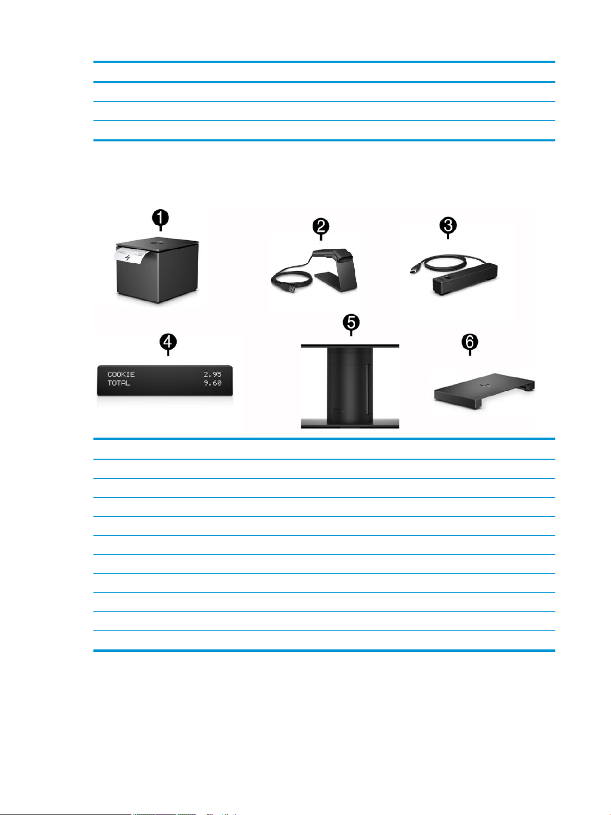
Peripherals
Description
(1) HP Engage One Serial USB Thermal Printer
(2) HP Engage One 2D Barcode Scanner
(3) HP Engage One Fingerprint Reader
(4) HP Engage One Top Mount 2x20 CFD
HP L8010t 10.1" Touch CFD
HP L8010 10.1" Non-Touch CFD
(5) HP Engage One Column Printer, black or white
(6) I/O Connectivity Base
Advanced (includes powered USBs)
Basic (does not include powered USBs)
12 Chapter 2 Illustrated parts catalog
Page 21

Cables and adapters
Description
Touch cable, 300/500nits
WLAN antenna cables
Printer serial cable
Printer USB cable
Fingerprint reader cable, USB Type-A to micro USB, 0.3 meter
Fingerprint reader cable, USB Type-A to micro USB, 1.8 meter
Column printer cable, 2 meter, 24V powered USB
Column printer cable, 26 cm, 24V powered USB
Column printer cable, 2 meter, USB Type-B to Type-A
Column printer cable, 23 cm, USB Type-B to Type-A
Column printer cable, 50 cm, cash drawer
24V to Y (Hosiden/Type-B), powered USB cable (for use with HP POS Hybrid Printer, MICR with Imaging Module)
24V powered USB cable (power only), Hosiden
USB Type-C cable, coiled
USB Type-C cable, straight
USB Type-C cable, 20V/3A, 0.43 meter
USB Type-C cable, 20V/3A, 1.8 meter
USB Type-C cable, VESA
USB Type-C cable connector restraint kit
Adapters
USB to serial
USB Type-C to VGA
USB Type-C to DisplayPort
USB Type-C to HDMI
Cables and adapters 13
Page 22

3 Routine care, SATA drive guidelines, and
disassembly preparation
This chapter provides general service information for the computer. Adherence to the procedures and
precautions described in this chapter is essential for proper service.
CAUTION: When the computer is plugged into an AC power source, voltage is always applied to the system
board. You must disconnect the power cord from the power source before opening the computer to prevent
system board or component damage.
Computer operating guidelines and routine care
Follow the guidelines below to properly set up and care for the computer:
●
HP recommends a 17 mm clearance around the vents on the computer head unit and I/O connectivity
base for heat dissipation.
●
Keep the computer away from excessive moisture, direct sunlight, and extremes of heat and cold.
●
Never operate the computer with any access panels removed.
●
Do not stack computers on top of each other or place computers so near each other that they are subject
to each other’s recirculated or preheated air.
●
If the computer is to be operated within a separate enclosure, intake and exhaust ventilation must be
provided on the enclosure, and the same operating guidelines listed above will still apply.
●
Keep liquids away from the computer and I/O connectivity base.
●
Never cover the vents on the computer or I/O connectivity base with any type of material.
●
Install or enable power management functions of the operating system or other software, including
sleep states.
●
Turn o the computer before you do either of the following:
–
Wipe the exterior of the computer with a soft, damp cloth as needed. Using cleaning products may
discolor or damage the nish.
–
Occasionally clean the air vents on all vented sides of the computer. Lint, dust, and other foreign
matter can block the vents and limit the airow.
NOTE: For more information on your retail system care and maintenance, refer to “Retail Point of Sales
Systems - Routine Care and Maintenance” available at http://www.hp.com/support.
Touch screen maintenance
Keep your display and touch sensor clean. The touch sensor requires very little maintenance. HP recommends
that you periodically clean the glass touch sensor surface. Be sure to turn o your display before cleaning.
Typically, an isopropyl alcohol and water solution ratio of 50:50 is the best cleaning agent for your touch
sensor. It is important to avoid using any caustic chemicals on the touch sensor. Do not use any vinegar-based
solutions.
14 Chapter 3 Routine care, SATA drive guidelines, and disassembly preparation
Page 23

Apply the cleaner with a soft, lint-free cloth. Avoid using gritty cloths. Always dampen the cloth and then
clean the sensor. Be sure to spray the cleaning liquid onto the cloth, not the sensor, so that drips do not seep
inside the display or stain the bezel.
MSR maintenance
To clean the MSR (magnetic strip reader), swipe a standard cleaning card through the MSR a couple of times.
You can order a standard cleaning card online. You can also put a thin oil-free cloth around a credit card.
Service considerations
Listed below are some of the considerations that you should keep in mind during the disassembly and
assembly of the computer.
Tools and software requirements
To service the computer, you need the following:
●
Torx T-15 screwdriver
●
Flat-bladed screwdriver (may sometimes be used in place of the Torx screwdriver)
●
Phillips #2 screwdriver
●
Phillips #1 screwdriver
●
Diagnostics software
●
Tamper-resistant T-10 screwdriver
Screws
The screws used in the computer are not interchangeable. They may have standard or metric threads and may
be of dierent lengths. If an incorrect screw is used during the reassembly process, it can damage the unit. HP
strongly recommends that all screws removed during disassembly be kept with the part that was removed,
then returned to their proper locations.
CAUTION: As each subassembly is removed from the computer, it should be placed away from the work area
to prevent damage.
Cables and connectors
Most cables used throughout the unit are at, exible cables. These cables must be handled with care to
avoid damage. Apply only the tension required to seat or unseat the cables during insertion or removal from
the connector. Handle cables by the connector whenever possible. In all cases, avoid bending or twisting the
cables, and ensure that the cables are routed in such a way that they cannot be caught or snagged by parts
being removed or replaced.
CAUTION: When servicing this computer, ensure that cables are placed in their proper location during the
reassembly process. Improper cable placement can damage the computer.
Lithium coin cell battery
The battery that comes with the computer provides power to the real-time clock and has a minimum lifetime
of about three years.
MSR maintenance 15
Page 24

See the appropriate removal and replacement chapter for the chassis you are working on in this guide for
instructions on the replacement procedures.
WARNING! This computer contains a lithium battery. There is a risk of re and chemical burn if the battery is
handled improperly. Do not disassemble, crush, puncture, short external contacts, dispose in water or re, or
expose it to temperatures higher than 140ºF (60ºC). Do not attempt to recharge the battery.
NOTE: Batteries, battery packs, and accumulators should not be disposed of together with the general
household waste. In order to forward them to recycling or proper disposal, please use the public collection
system or return them to HP, their authorized partners, or their agents.
Electrostatic discharge information
A sudden discharge of static electricity from your nger or other conductor can destroy static-sensitive
devices or microcircuitry. Often the spark is neither felt nor heard, but damage occurs. An electronic device
exposed to electrostatic discharge (ESD) may not appear to be aected at all and can work perfectly
throughout a normal cycle. The device may function normally for a while, but it has been degraded in the
internal layers, reducing its life expectancy.
Networks built into many integrated circuits provide some protection, but in many cases, the discharge
contains enough power to alter device parameters or melt silicon junctions.
Generating static
The following table shows that:
●
Dierent activities generate dierent amounts of static electricity.
●
Static electricity increases as humidity decreases.
Relative Humidity
Event 55% 40% 10%
Walking across carpet
Walking across vinyl oor
Motions of bench worker
Removing DIPs from plastic tube
Removing DIPs from vinyl tray
Removing DIPs from Styrofoam
Removing bubble pack from PCB
Packing PCBs in foam-lined box
These are then multi-packaged inside plastic tubes, trays, or Styrofoam.
7,500 V
3,000 V
400 V
400 V
2,000 V
3,500 V
7,000 V
5,000 V
15,000 V
5,000 V
800 V
700 V
4,000 V
5,000 V
20,000 V
11,000 V
NOTE: 700 volts can degrade a product.
35,000 V
12,000 V
6,000 V
2,000 V
11,500 V
14,500 V
26,500 V
21,000 V
Preventing electrostatic damage to equipment
Many electronic components are sensitive to ESD. Circuitry design and structure determine the degree of
sensitivity. The following packaging and grounding precautions are necessary to prevent damage to electric
components and accessories.
16 Chapter 3 Routine care, SATA drive guidelines, and disassembly preparation
Page 25

●
To avoid hand contact, transport products in static-safe containers such as tubes, bags, or boxes.
●
Protect all electrostatic parts and assemblies with conductive or approved containers or packaging.
●
Keep electrostatic sensitive parts in their containers until they arrive at static-free stations.
●
Place items on a grounded surface before removing them from their container.
●
Always be properly grounded when touching a sensitive component or assembly.
●
Avoid contact with pins, leads, or circuitry.
●
Place reusable electrostatic-sensitive parts from assemblies in protective packaging or conductive
foam.
Personal grounding methods and equipment
Use the following equipment to prevent static electricity damage to equipment:
●
Wrist straps are exible straps with a maximum of one-megohm ± 10% resistance in the ground cords.
To provide proper ground, a strap must be worn snug against bare skin. The ground cord must be
connected and t snugly into the banana plug connector on the grounding mat or workstation.
●
Heel straps/Toe straps/Boot straps can be used at standing workstations and are compatible with
most types of shoes or boots. On conductive oors or dissipative oor mats, use them on both feet with
a maximum of one-megohm ± 10% resistance between the operator and ground.
Static Shielding Protection Levels
Method Voltage
Antistatic plastic
Carbon-loaded plastic
Metallized laminate
Grounding the work area
To prevent static damage at the work area, use the following precautions:
●
Cover the work surface with approved static-dissipative material. Provide a wrist strap connected to the
work surface and properly grounded tools and equipment.
●
Use static-dissipative mats, foot straps, or air ionizers to give added protection.
●
Handle electrostatic sensitive components, parts, and assemblies by the case or PCB laminate. Handle
them only at static-free work areas.
●
Turn o power and input signals before inserting and removing connectors or test equipment.
●
Use xtures made of static-safe materials when xtures must directly contact dissipative surfaces.
●
Keep work area free of nonconductive materials such as ordinary plastic assembly aids and Styrofoam.
●
Use eld service tools, such as cutters, screwdrivers, and vacuums, that are conductive.
1,500
7,500
15,000
Electrostatic discharge information 17
Page 26

Recommended materials and equipment
Materials and equipment that are recommended for use in preventing static electricity include:
●
Antistatic tape
●
Antistatic smocks, aprons, or sleeve protectors
●
Conductive bins and other assembly or soldering aids
●
Conductive foam
●
Conductive tabletop workstations with ground cord of one-megohm +/- 10% resistance
●
Static-dissipative table or oor mats with hard tie to ground
●
Field service kits
●
Static awareness labels
●
Wrist straps and footwear straps providing one-megohm +/- 10% resistance
●
Material handling packages
●
Conductive plastic bags
●
Conductive plastic tubes
●
Conductive tote boxes
●
Opaque shielding bags
●
Transparent metallized shielding bags
●
Transparent shielding tubes
18 Chapter 3 Routine care, SATA drive guidelines, and disassembly preparation
Page 27

4 Removal and replacement procedures
NOTE: HP continually improves and changes product parts. For complete and current information on
supported parts for your computer, go to http://partsurfer.hp.com, select your country or region, and then
follow the on-screen instructions.
Adherence to the procedures and precautions described in this chapter is essential for proper service. After
completing all necessary removal and replacement procedures, run the Diagnostics utility to verify that all
components operate properly.
NOTE: Not all features listed in this guide are available on all computers.
Preparation for disassembly
See Routine care, SATA drive guidelines, and disassembly preparation on page 14 for initial safety procedures.
1. Remove/disengage any security devices that prohibit opening the computer.
2. Shut down the computer properly through the operating system, then turn o any external devices.
3. Disconnect the power cord from the power outlet.
CAUTION: Regardless of the power-on state, voltage is always present on the system board as long as
the system is plugged into an active AC outlet. You must disconnect the power cord and wait
approximately 30 seconds for the power to drain to avoid damage to the internal components of the
computer.
4. Disconnect all cables from the rear I/O connectors.
CAUTION: The screws used in the computer are of dierent thread sizes and lengths; using the wrong screw
in an application may damage the unit.
NOTE: During disassembly, label each cable as you remove it, noting its position and routing. Keep all
screws with the units removed.
Preparation for disassembly 19
Page 28
Attaching an I/O connectivity base to the Engage One
You can attach an I/O connectivity base to the bottom of the computer’s stand.
1. Prepare the computer for disassembly (Preparation for disassembly on page 19).
2. Remove the cover on the I/O connectivity base by removing the four screws on the underside of the I/O
connectivity base (1), and then lifting the cover o the I/O connectivity base (2).
3. Connect the USB Type-C power cable to the USB Type-C port on the underside of the stand’s column.
20 Chapter 4 Removal and replacement procedures
Page 29
4. Place the I/O connectivity base onto the bottom of the stand (1), and then tighten the four screws on the
underside of the I/O connectivity base (2) to secure the I/O connectivity base to the stand. Be sure that
the USB Type-C power cable is routed through the gap between the back of the I/O connectivity base and
the stand.
5. To connect and secure the USB Type-C power cable, attach the cable clip to the cable (1), insert the cable
tie into the hole (2) below the USB Type-C port on the hub, and then slide the cable clip onto the cable tie
and connect the cable to the port (3).
6. Connect the I/O connectivity base’s AC adapter to the I/O connectivity base and a grounded AC outlet.
Attaching an I/O connectivity base to the Engage One 21
Page 30
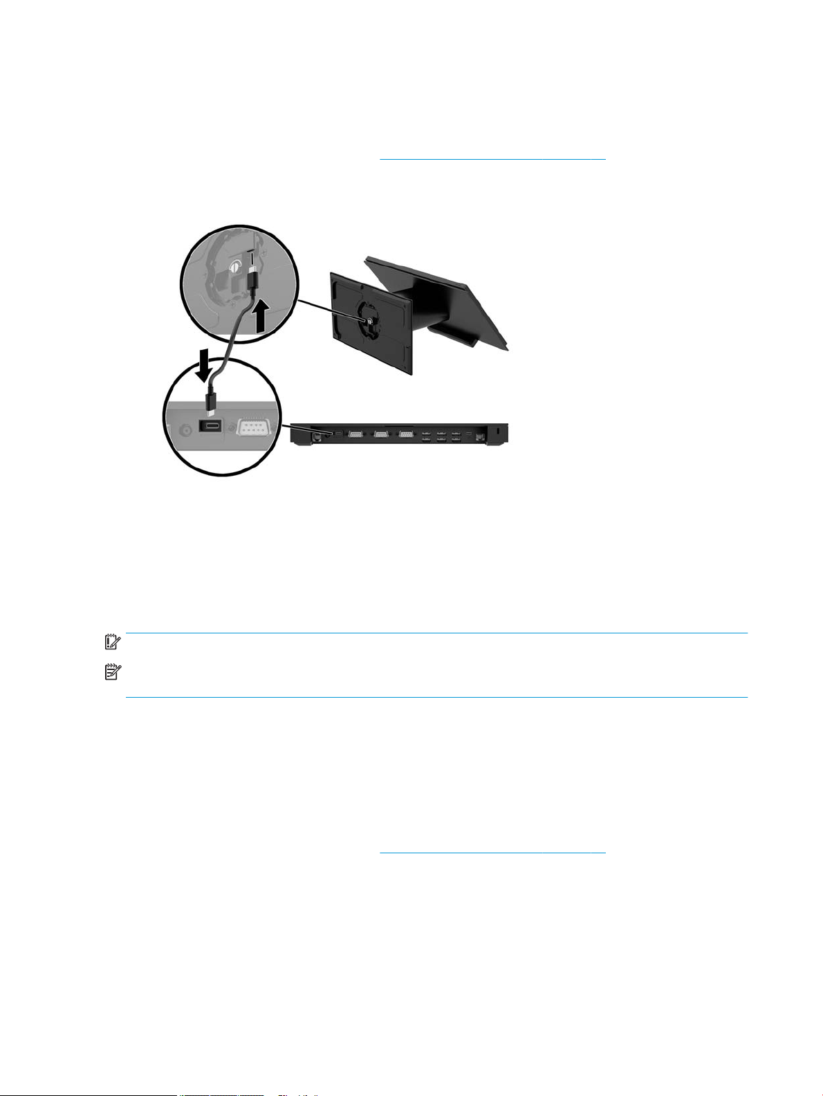
Connecting a standalone I/O connectivity base to the Engage One
1. Prepare the computer for disassembly (Preparation for disassembly on page 19).
2. Connect the USB Type-C power cable to the USB Type-C port on the underside of the stand’s column and
to the USB Type-C power port on the I/O connectivity base.
3. Connect the I/O connectivity base’s power supply to the I/O connectivity base and a grounded AC outlet.
Conguring the I/O connectivity base’s powered serial ports
The serial ports can be congured as standard (non-powered) serial ports or powered serial ports. Some
devices use a powered serial port. If the serial port is congured as a powered port, devices that support a
powered serial interface do not require an external power source.
IMPORTANT: The system must be powered o before connecting or disconnecting serial port devices.
NOTE: The I/O connectivity base ships with all serial ports congured in standard non-powered serial mode
(0 volts) by default.
There are three voltage settings for each serial port.
●
0 volts
●
5 volts
●
12 volts
To change the voltage settings for a powered serial port:
1. Prepare the computer for disassembly (Preparation for disassembly on page 19).
22 Chapter 4 Removal and replacement procedures
Page 31

2. Remove the ve screws on the underside of the I/O connectivity base (1) that secure the bottom plate to
the I/O connectivity base, and then remove the bottom plate from the I/O connectivity base (2).
3. Adjust the voltage select switch behind each serial port to the desired setting.
Conguring the I/O connectivity base’s powered serial ports 23
Page 32

4. Place the bottom plate onto the I/O connectivity base (1), and then secure the plate to the I/O
connectivity base with the ve screws (2).
5. Reconnect the I/O connectivity base’s power cord and peripheral devices.
Connecting a standalone optional ngerprint reader to the I/O
connectivity base
The optional ngerprint reader can be used as a standalone device or it can be attached to the I/O
connectivity base. Follow the procedure below to connect a standalone ngerprint reader to the I/O
connectivity base.
1. Prepare the computer for disassembly (Preparation for disassembly on page 19).
2. Connect the USB cable to the ngerprint reader (1) and route the cable through the routing channel (2)
on the ngerprint reader.
24 Chapter 4 Removal and replacement procedures
Page 33

3. Connect the ngerprint reader USB cable to a USB Type-A port on the I/O connectivity base.
4. Reconnect the I/O connectivity base and computer power cords.
Attaching an optional ngerprint reader to the I/O connectivity
base
The optional ngerprint reader can be used as a standalone device or it can be attached to the I/O
connectivity base. Follow the procedure below to attach the ngerprint reader to the I/O connectivity base.
NOTE: You can attach the ngerprint reader to either side of the I/O connectivity base, but if you attach it to
the left side of the I/O connectivity base, the ngerprint reader will cover the microSD slot and the headset
jack on the I/O connectivity base.
1. Prepare the computer for disassembly (Preparation for disassembly on page 19).
2. Place the ngerprint reader (1) on the riser (2), and then attach the mounting bracket (3) and cable
routing clip (4) to the ngerprint reader and riser with the two long screws (5) included with the
ngerprint reader.
Attaching an optional ngerprint reader to the I/O connectivity base 25
Page 34

3. Connect the USB cable to the ngerprint reader (1) and route the cable under the routing clip on the
ngerprint reader (2). Remove the mounting screw (3) from the underside of the I/O connectivity base,
and then attach the bracket on the ngerprint reader assembly to the underside of the I/O connectivity
base (4) using the screw that was removed from the base and the short screw included in the kit.
4. Connect the ngerprint reader cable to a USB Type-A port on the I/O connectivity base.
5. Reconnect the I/O connectivity base and computer power cords.
26 Chapter 4 Removal and replacement procedures
Page 35

Removing and attaching the Engage One head unit to the stand
1. Prepare the computer for disassembly (Preparation for disassembly on page 19).
2. Insert a thin metal tool, such as a screwdriver, into the computer head unit release hole (1) on the stand
to depress the release button, and then pull the head unit from the stand (2).
NOTE: If a security screw is installed in the release hole, remove the screw with a T-10 screwdriver to
access the release button.
To attach the head unit to the stand, align the guide posts on the rear of the computer head unit with the
corresponding holes in the stand’s column, and then press the head unit onto the column.
Removing and attaching the Engage One head unit to the stand 27
Page 36

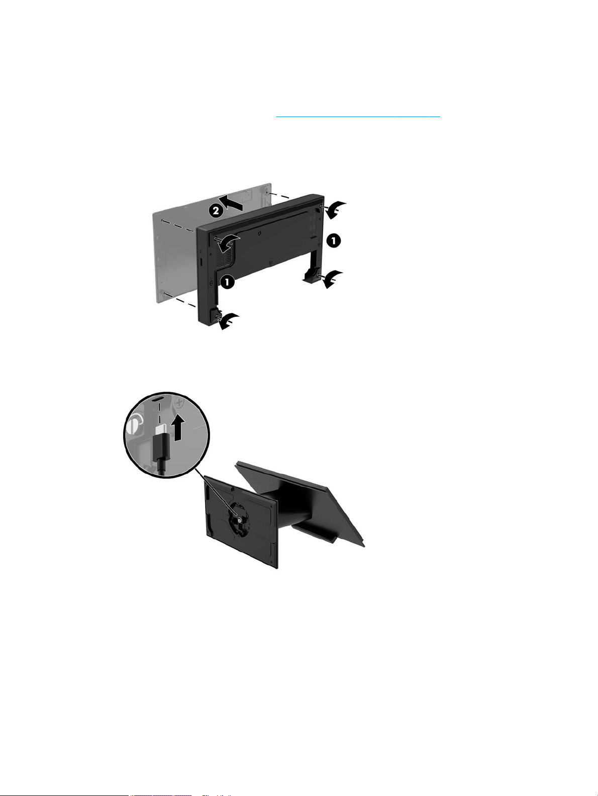
Mounting the Engage One head unit to a wall
You can use an optional VESA mounting bracket to mount the computer head unit to a wall.
Screws sizes are 241-I052-M004 for the security screw and 241-I042-M059 for the VESA mount screw.
1. Prepare the computer for disassembly (Preparation for disassembly on page 19).
2. Remove the computer head unit from the stand (if necessary) (Removing and attaching the Engage One
head unit to the stand on page 27).
3. Attach the VESA mounting bracket to a wall.
4. Connect the USB Type-C power cable to the USB Type-C port on the VESA mounting bracket (1). Align the
guide posts on the rear of the computer head unit with the corresponding holes in the VESA mounting
bracket, and then press the head unit onto the VESA mounting bracket (2).
You also have the option of routing the USB Type-C cable out the rear of the VESA bracket and through a
wall instead of attaching a USB Type-C cable to the port on the side of the bracket.
a. Press the rear cover release tab (1) on the VESA bracket, and then pull the rear cover o the VESA
bracket (2). Unplug the cable from the inside of the VESA bracket.
28 Chapter 4 Removal and replacement procedures
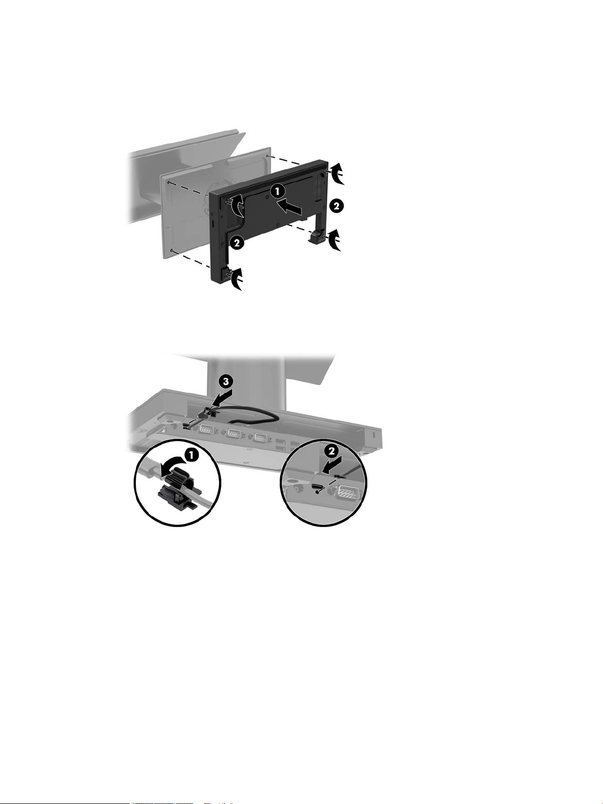
Page 37

b. Route the USB Type-C cable from the inside of the VESA bracket through the slot on the bracket’s
rear cover (1), and then replace the rear cover (2).
5. Connect the power cable from the VESA bracket to a wall outlet or I/O connectivity base.
Mounting the Engage One head unit to a wall 29
Page 38

Mounting the Engage One to a counter top
You can use an optional counter top mounting bracket to mount the computer head unit and column to a
counter top.
NOTE: The mounting bracket requires an 80 mm hole in the counter top. The thickness of the counter top
must be 10 mm to 50 mm.
1. If the stand’s base is attached to the column, remove the screw on the underside of the column (1), and
then remove the base from the column (2).
2. Route the cable(s) through the routing hole on the top piece of the mounting bracket (1) and attach the
cable(s) to the bottom of the column (2).
NOTE: If the column has a printer, there are four cables to connect. If it does not have a printer, there is
one cable to connect.
30 Chapter 4 Removal and replacement procedures
Page 39

3. Hold the top piece of the mounting bracket against the bottom of the column, route the cables through
the hole in the mounting surface, and then place the column over the hole on the mounting surface.
4. The bottom piece of the mounting bracket can be oriented in two ways, depending on the thickness of
your mounting surface. Orient the bracket properly for your application before attaching it.
5. Route the cables through the hole in the bottom piece of the mounting bracket (1). Press the mounting
bracket against the bottom of the mounting surface (2), and then insert the screw (3) though the
mounting bracket. Tighten the screw (4) so that the screw is fully inserted into the column, and then
tighten the wing nut (5) on the screw to fasten the bracket to the mounting surface.
NOTE: Screw size: 221-M006-001.
Mounting the Engage One to a counter top 31
Page 40

Installing a security cable on the I/O connectivity base
You can secure the I/O connectivity base to a xed object with an optional Keyed Cable lock security cable
extension and an optional security cable available from HP.
NOTE: The security cable is sold separately as an aftermarket option kit only.
32 Chapter 4 Removal and replacement procedures
Page 41

Installing a security cable on the Engage One column
You can secure the I/O connectivity base to a xed object with an optional Keyed Cable lock security cable
extension and an optional security cable available from HP.
NOTE: The security cable is sold separately as an aftermarket option kit only.
1. Remove the screw from the bottom of the column (1).
2. Attach the security cable extension to the bottom of the column using the tamper-resistant screw (2)
included with the security cable extension.
3. Secure the other end of the security cable extension with a security cable (3).
Installing a security cable on the Engage One column 33
Page 42

Installing a security screw on the Engage One head unit and stand
You can insert a tamper-resistant security screw into the computer’s column with a T-10 screwdriver to
prevent access to the computer head unit’s release button.
1. Remove the security screw from the bottom of the stand’s column.
2. Install the security screw in the release button hole on the stand’s column.
34 Chapter 4 Removal and replacement procedures
Page 43

Installing a security screw on the Engage One head unit and VESA mount
You can insert a tamper-resistant security screw into the computer’s VESA mount with a T-10 screwdriver to
prevent access to the computer head unit’s release button.
1. Press the rear cover release tab (1) on the VESA bracket, and then pull the rear cover o the VESA
bracket (2). Then remove the security screw (3) from inside the VESA bracket, and then replace the rear
cover (4).
. Press the head unit onto the VESA mount (1) if it is not already attached, and then install the security
2
screw (2) in the release button hole on the VESA mount.
Removing and replacing the column printer
1. Prepare the computer for disassembly (Preparation for disassembly on page 19).
2. Remove the receipt paper from the printer.
3. Disconnect the printer and system power sources and any attached devices.
4. Place the computer with the display panel face down on a at surface covered by a soft clean cloth, and
then remove the I/O connectivity base (Attaching an I/O connectivity base to the Engage One
on page 20)
5. Remove the USB-C power cable.
6. Loosen the captive screw that secures the stand base to the printer base plate (1).
Installing a security screw on the Engage One head unit and VESA mount 35
Page 44

7. Lift stand base (2) to access the cables connected to the printer.
8. Remove the cables from the clips on the printer base plate (1).
9. Disconnect the cables from the printer and remove the cables and stand base (2).
10. Rotate the column up to expose the head unit release hole (1).
IMPORTANT: If a security screw is installed in the release hole, remove it to access the release button .
36 Chapter 4 Removal and replacement procedures
Page 45

11. Insert a screwdriver into the release hole to depress the release button (2), and then pull the column up
and o of the head unit (3).
12. Remove the column printer door cover:
a. Open the printer door (1).
b. Remove the two Phillips head screws with the lock washers and bushings (2) from the top and
bottom of the door cover.
c. Use a small at head screwdriver to pry the retaining tab from behind the door cover hook (1).
d. Press the door cover hook out of the slot in the door frame (2).
NOTE: You may need to use a at head screwdriver to help disengage the hook from the slot.
Removing and replacing the column printer 37
Page 46

e. Pull the door cover o of the door frame (3).
13. Close the printer door.
14. Remove the four Phillips screws that secure the stand cable connector housing, and then pull the cable
cover away from the printer base.
38 Chapter 4 Removal and replacement procedures
Page 47

15. Remove the three Phillips head screws that secure the printer engine to the bottom of the column.
IMPORTANT: Do not remove any screws marked with 'P' on the base plate.
16. Slide the printer engine about ¼ inch (0.6 cm) out of the column (1).
17. Carefully remove the paper feed button from the opening in the column (2).
18. Continue sliding the printer engine out of the column and remove (3).
To replace the column printer, reverse the removal procedures. Please note the following tips when replacing
the column printer.
●
Remove the alignment pin from the bottom of printer engine.
Removing and replacing the column printer 39
Page 48

●
Holding the column with the door side up, ensure that the stand cable is on the far side of the alignment
rod (1).
While holding the paper feed actuator arm down, slide the printer engine into the column until the
actuator arm is visible through hole (2).
●
With the alignment stud oriented toward the top of the column, place the paper feed button into the
opening in the column (1).
Continue sliding the printer engine into the column until the button is fully engaged and the engine is
fully seated (2).
40 Chapter 4 Removal and replacement procedures
Page 49

Removing the display panel
You must remove the display panel from the computer head unit to access internal computer components.
1. Prepare the computer for disassembly (Preparation for disassembly on page 19).
2. Remove the computer head unit from the stand (Removing and attaching the Engage One head unit to
the stand on page 27).
3. Loosen the three captive screws in the slot on the bottom of the computer head unit.
. Separate the computer’s display panel from the computer head unit at the connection points, and then
4
lift the display panel up approximately 2.5 cm (one inch).
IMPORTANT: Do not lift the display panel higher than 2.5 cm (one inch) from the computer head unit.
An internal cable must be disconnected before the display panel can be fully removed.
5. Holding the display panel 2.5 cm (one inch) from the computer head unit, shift the display panel forward
no more than 7.5 cm (three inches) (1) to access the display cable connection. Lift the edges of the tape
that covers the display cable connection (2), and then disconnect the display cable from the connector
on the system board (3) by pulling the tab on the cable end.
IMPORTANT: Be careful not to fold the edges of the tape. It must be replaced when the display cable is
reconnected.
Removing the display panel 41
Page 50

6. Rotate the display panel over the top of the computer head unit and onto a at surface covered by a soft
clean cloth.
IMPORTANT: The touch and WLAN cables will still be connected between the top of the display panel
and the top of the computer head unit. Be careful when removing the display panel so that the cables do
not become disconnected.
7. Disconnect the touch cable from the system board and the WLAN antennas from the WLAN module.
To replace the display panel, reverse the removal procedures.
System board components
Refer to the table below to locate the system board components referenced in this guide.
System board components
(1) SD card slot (4) WLAN module
(2) CFD connector (5) M.2 SSD
(3) Memory modules
42 Chapter 4 Removal and replacement procedures
Page 51

Installing a 2 x 20 customer-facing display (CFD)
1. Prepare the computer for disassembly (Preparation for disassembly on page 19).
2. Remove the computer head unit from the stand (Removing and attaching the Engage One head unit to
the stand on page 27).
3. Remove the display panel from the computer head unit (Removing the display panel on page 41)
4. Remove the rubber stoppers from the CFD cable routing channel and the two CFD screw holes.
5. Route the CFD cable through the routing channel on the computer head unit (1). Pull the cable all the
way through the channel (2), and then slide the screw tabs on the CFD into the slots on the computer
head unit (3).
Installing a 2 x 20 customer-facing display (CFD) 43
Page 52

6. Install the two screws that attach the CFD to the computer head unit (1), and then connect the CFD cable
to the connector on the system board (2).
IMPORTANT: Make sure the entire CFD cable is pulled all the way through the head unit routing
channel before installing the CFD so that the cable does not get pinched between the CFD and the head
unit.
7. Replace the computer head unit’s display panel.
8. Attach the computer head unit to the stand. See Removing and attaching the Engage One head unit to
the stand on page 27.
9. Reconnect the power cord and press the power button.
44 Chapter 4 Removal and replacement procedures
Page 53

Memory modules
The computer comes with at least one preinstalled double data rate 4 synchronous dynamic random access
memory (DDR4-SDRAM) small outline dual in-line memory module (SODIMM). There are two memory sockets
on the system board that can be populated with up to 32 GB of memory.
DDR4-SDRAM SODIMMs
For proper system operation, the memory modules must be 1.2 volt DDR4-SDRAM SODIMMs and adhere to
the following specications:
●
Industry-standard 260-pin
●
Unbuered non-ECC PC4-19200 DDR4-2400 MHz-compliant
●
Support CAS latency DDR4 2400 MHz (17-17-17 timing)
●
Contain the mandatory Joint Electronic Device Engineering Council (JEDEC) specication
The computer supports the following:
●
512-Mbit, 1-Gbit, 2-Gbit, 4-Gbit, and 8-Gbit non-ECC memory technologies
●
Single-sided and double-sided SODIMMs
●
The following SODIMMs are oered:
–
4 GB (1 x 4 GB) DDR 42400 SODIMM memory
–
8 GB (1 x 8 GB) DDR 42400 SODIMM memory
–
8 GB (2 x 4 GB) DDR 42400 SODIMM memory
–
16 GB (1 x 16 GB) DDR 42400 SODIMM memory
–
16 GB (2 x 8 GB) DDR 42400 SODIMM memory
–
32 GB (2 x 16 GB) DDR 42400 SODIMM memory
NOTE: The system will not operate properly if you install unsupported SODIMMs.
Removing a SODIMM
CAUTION: You must disconnect the power cord and wait approximately 30 seconds for the power to drain
before replacing the memory module. Regardless of the power-on state, voltage is always supplied to the
memory module as long as the computer is plugged into an active AC outlet. Adding or removing the memory
module while voltage is present may cause irreparable damage to the memory module or system board.
The memory module socket has gold-plated metal contacts. When upgrading the memory, it is important to
use a memory module with gold-plated metal contacts to prevent corrosion and/or oxidation resulting from
having incompatible metals in contact with each other.
Static electricity can damage the electronic components of the computer or optional cards. Before beginning
these procedures, ensure that you are discharged of static electricity by briey touching a grounded metal
object. For more information, refer to
When handling a memory module, be careful not to touch any of the contacts. Doing so may damage the
module.
Electrostatic discharge information on page 16.
To remove and install a memory module:
Memory modules 45
Page 54

1. Prepare the computer for disassembly (Preparation for disassembly on page 19).
2. Remove the computer head unit from the stand (Removing and attaching the Engage One head unit to
the stand on page 27).
3. Remove the display panel from the computer head unit (Removing the display panel on page 41)
4. Remove the shield over the memory modules by pulling the tab on the shield up (1), and then lifting the
shield from the system board (2).
5. To remove a memory module, press outward on the two latches on each side of the memory module (1),
and then pull the memory module out of the socket (2).
46 Chapter 4 Removal and replacement procedures
Page 55

6. To install a memory module, slide the new memory module into the socket at approximately a 30° angle
(1), and then press the memory module down into the socket (2) so that the latches lock it in place.
NOTE: A memory module can be installed in only one way. Match the notch on the module with the tab
on the memory socket.
7. Replace the shield over the memory modules by pressing the left side of the shield down onto the
system board (1) and then the pressing the right side down (2).
The computer automatically recognizes the additional memory when you turn on the computer.
Memory modules 47
Page 56

Removing and installing an M.2 solid-state drive (SSD)
IMPORTANT: If you are replacing an SSD , be sure to back up the data from the old SSD so that you can
transfer the data to the new SSD.
To remove and install an M.2 storage device:
1. Prepare the computer for disassembly (Preparation for disassembly on page 19).
2. Remove the computer head unit from the stand (Removing and attaching the Engage One head unit to
the stand on page 27).
3. Remove the display panel from the computer head unit (Removing the display panel on page 41)
4. To remove an SSD, remove the screw that secures the SSD to the system board (1), and then slide the
SSD out of the system board connector (2).
5. To install an SSD, slide the connector end of the SSD into the system board connector (1), and then
secure the other end of the SSD to the system board with the screw (2).
48 Chapter 4 Removal and replacement procedures
Page 57

Removing the WLAN module
Description
802.11 a/b/g/n + Bluetooth 4.0, 2x2
802.11 a/b/g/n + Bluetooth 4.0, 2x2 (for use only in Indonesia)
Intel Dual Band Wireless-AC 8260
The WLAN module is secured with one screw and has two connected antennas.
To remove the WLAN module:
1. Prepare the computer for disassembly (Preparation for disassembly on page 19)
2. Remove the computer head unit from the stand (Removing and attaching the Engage One head unit to
the stand on page 27).
3. Remove the display panel from the computer head unit (Removing the display panel on page 41)
4. To remove a WLAN module, disconnect the WLAN cables (1), remove the screw (2) that secures the
module to the system board, and then slide the module out of the system board connector (3).
IMPORTANT: The WLAN cables and connectors are labeled 1 and 2. Make sure that you match the
numbered labels on the WLAN module with the numbered labels on the cables when reconnecting the
cables.
Removing the WLAN module 49
Page 58

5. To install a WLAN module, slide the connector end of the module into the system board connector (1),
then secure the other end of the module to the system board with the screw (2), and then connect the
two cables from the display panel to the connectors on the WLAN module (3).
IMPORTANT: The WLAN cables and connectors are labeled 1 and 2. Make sure that you match the
numbered labels on the WLAN module with the numbered labels on the cables when connecting the
cables.
To install a WLAN module, reverse the removal procedures.
50 Chapter 4 Removal and replacement procedures
Page 59

Removing the heat sink
The heat sink is secured to the system board, under the heat sink shield.
To remove the heat sink:
1. Prepare the computer for disassembly (Preparation for disassembly on page 19).
2. Remove the computer head unit from the stand (Removing and attaching the Engage One head unit to
the stand on page 27).
3. Remove the display panel from the computer head unit (Removing the display panel on page 41)
4. In the order indicated on the heat sink, loosen the ve captive Phillips screws that secure the heat sink
to the system board (1) - (5).
5. Lift the heat sink o the system board (6).
CAUTION: To reduce a degradation in thermal performance, be sure not to touch the thermal grease
on the surface of the processor or the heat sink.
To replace the heat sink, reverse the removal procedures.
Removing the heat sink 51
Page 60

Removing the fan assembly
The fan assembly is secured with four screws and has one cable.
To remove the fan:
1. Prepare the computer for disassembly (Preparation for disassembly on page 19).
2. Remove the computer head unit from the stand (Removing and attaching the Engage One head unit to
the stand on page 27).
3. Remove the display panel from the computer head unit (Removing the display panel on page 41)
4. Disconnect the fan cable from the system board (1), and then remove the tape that secures the cable to
the system board (2).
5. Loosen the four captive Phillips screws (3) that secure the fan assembly to the computer head unit.
6. Remove the fan assembly from the computer head unit (4).
To reinstall the fan assembly, reverse the removal procedure.
52 Chapter 4 Removal and replacement procedures
Page 61

Removing the speakers
The computer uses two separate speakers located on the left and right sides. Each speaker has a cable that
connects to a separate connector.
To remove the speakers:
1. Prepare the computer for disassembly (Preparation for disassembly on page 19).
2. Remove the computer head unit from the stand (Removing and attaching the Engage One head unit to
the stand on page 27).
3. Remove the display panel from the computer head unit (Removing the display panel on page 41)
4. For each speaker, disconnect the cable from the system board (1), and then use a at tool to pry each
speaker out of the computer head unit (2). The speakers are held in place with adhesive.
To replace the speakers, reverse the removal procedures.
Removing the speakers 53
Page 62

Removing the power button board
The power button board is secured with one Phillips screws.
To remove the power button board:
1. Prepare the computer for disassembly (Preparation for disassembly on page 19).
2. Remove the computer head unit from the stand (Removing and attaching the Engage One head unit to
the stand on page 27).
3. Remove the display panel from the computer head unit (Removing the display panel on page 41)
4. Disconnect the cable from the system board ZIF connector (1), and then lift the cable up to disengage it
from the adhesive that secures the cable to the system board.
5. Remove the Phillips screw (2).
6. Lift the power button board out of the computer head unit (3).
To reinstall the power button board, reverse the removal procedure.
54 Chapter 4 Removal and replacement procedures
Page 63

Removing the MSR (Magnetic Stripe Reader)
The MSR consists of two main components that are connected together into one assembly.
To remove the MSR assembly:
1. Prepare the computer for disassembly (Preparation for disassembly on page 19).
2. Remove the computer head unit from the stand (Removing and attaching the Engage One head unit to
the stand on page 27).
3. Remove the display panel from the computer head unit (Removing the display panel on page 41)
4. Remove the top screw (1) and bracket (2), and then remove the bottom Phillips screw (3) and bracket (4)
from the reader.
5. Disconnect the MSR board cable from the system board (1).
TIP: Take extra care when disconnecting the cable. Pulling on the cable prematurely, before it is
disconnected, could cause damage to the connector.
6. Remove the Phillips screw (2) from the MSR board.
Removing the MSR (Magnetic Stripe Reader) 55
Page 64

7. Lift the board straight up and o the posts (3).
8. Remove the MSR (assembly from the computer head unit.
MSR conguration
LED swipe code: green = good; red = bad
Single beep = good read; three beeps = good read on all three tracks
For information about MSR encryption, see Solving retail system-specic problems on page 103.
Verifying a successful installation of the MSR
To verify a successful installation of the MSR:
1. Check Device Manager and verify that the computer has found the MSR hardware and loaded its drivers
successfully.
2. Test the MSR to ensure it is reading magnetic data as follows:
a. Make sure the device is in USB-HID-KBD mode (default for the MSR).
b. Open Microsoft Notepad and swipe a credit card.
c. Verify that data appears in Notepad (the data will be unreadable). If nothing appears in Notepad,
conrm that the MSR is in USB-HID-KB mode.
Testing the MSR in USG HID mode
To test the MSR in USB HID mode, the MSR OPOS driver must be installed. To verify the installation:
1. Launch the MSR OPOS Test utility from Windows start menu.
2. Open, Claim, and Enable [O/C/E] (DeviceEnabled) the device in OPOS or JPOS.
56 Chapter 4 Removal and replacement procedures
Page 65

3. Swipe a credit card.
4. Disable, Release, and Close [D/R/C] the test application.
TIP: USB HID mode requires an application that uses OPOS or JPOS drivers to conrm that the MSR is
able to read the data.
Non-encrypted or encrypted:
HID MODE + NATIVE DRIVER
Human Interface Devices\USB Input Device
USB\VID_03F0&PID_0457
HID-KEYBOARD MODE + NATIVE DRIVER (DEFAULT)
Human Interface Devices\USB Input Device
USB\VID_03F0&PID_0557
Keyboards\HID Keyboard Device
HID\VID_03F0&PID_0557
To reinstall the MSR assembly, reverse the removal procedure.
Enabling encryption on the MSR
RKI (Remote Key Injection) over the Internet is the only way to encrypt the MSR other then sending the entire
system to a Key Injection Facility (KIF).
NOTE: Injecting the key using RKI can only be performed by the company named ‘ID Tech.’
ID Tech provides the necessary forms, procedures, tools, information, and timelines.
1. Contact ID Tech, which will provide a Windows-based computer remote key loading software application.
The software can run independently or be integrated within the business application.
2. The Remote Key Loading software communicates with ID Tech devices through serial (RS232) and USB
interfaces.
You can also use Remote Key Loading software to retrieve a serial number and to nd out if readers
support remote key injection.
3. Make sure that the computer has internet connectivity. The Remote Key Loading software will
automatically connect to an ID Tech remote key loading server and send/receive an encrypted package
between the remote key loading server and ID Tech devices.
Removing the MSR (Magnetic Stripe Reader) 57
Page 66

Removing the MSR LED board
The MSR LED board is a separate component from the MSR. It is secured with one Phillips screw.
To remove the MSR LED board:
1. Prepare the computer for disassembly (Preparation for disassembly on page 19).
2. Remove the computer head unit from the stand (Removing and attaching the Engage One head unit to
the stand on page 27).
3. Remove the display panel from the computer head unit (Removing the display panel on page 41)
4. Disconnect the cable from the system board (1).
TIP: Take extra care when disconnecting the cable. Pulling on the cable prematurely, before it is
disconnected, could cause damage to the connector.
5. Remove the Phillips screw (2) that secures the board to the computer head unit.
6. Remove the board and cable assembly from the computer head unit (3).
To install the MSR LED board, reverse the removal procedures.
58 Chapter 4 Removal and replacement procedures
Page 67

Removing the system board
NOTE: All system board spare part kits include replacement thermal material. System boards include an
integrated Intel processor.
The system board is secured with six screws. Additionally, the system board is secured by the display
connector from the rear of the display.
To remove the system board:
1. Prepare the computer for disassembly (Preparation for disassembly on page 19).
2. Remove the computer head unit from the stand (Removing and attaching the Engage One head unit to
the stand on page 27).
3. Remove the display panel from the computer head unit (Removing the display panel on page 41)
4. Remove the heat sink (Removing the heat sink on page 51).
5. Remove the power button board (Removing the power button board on page 54).
6. When replacing the system board, make sure the following components are removed from the defective
system board and installed on the replacement system board:
●
Memory modules (Memory modules on page 45)
●
M.2 storage device (Removing and installing an M.2 solid-state drive (SSD) on page 48)
●
WLAN module (Removing the WLAN module on page 49)
7. Position the computer head unit upside down.
8. Remove the two Phillips screws and lift o the connector.
Removing the system board 59
Page 68

9. Disconnect the following cables from the system board:
(1) MSR LED board
(2) Fingerprint reader board
(3) Right speaker
(4) Power button board
(5) RTC battery
(6) Left speaker
(7) Fan assembly
10. Remove the 6 Phillips screws that secure the system board to the computer head unit (1).
11. Remove the system board from the computer head unit (2).
To install the system board, reverse the removal procedures.
NOTE: When replacing the system board, you must change the chassis serial number in the BIOS.
60 Chapter 4 Removal and replacement procedures
Page 69

System board callouts
Sys Bd Label Color Component Sys Bd Label Color Component
BAT White RTC battery MSR LED White MSR LED board
CMOS Yellow Reset CMOS P71 Black Power button board
CPU FAN Black Fan assembly SSD Black Solid-state drive
DIMM1 Black Memory module SPKR_L Black Speaker
DIMM3 Black Memory module SPKR_R Black Speaker
eDP Silver Display connector TOUCH White Touch board
MSR Black MSR board WLAN Black WLAN module
Removing the system board 61
Page 70

Removing the antennas
The wireless antenna cables connect from the WLAN module to antennas at the top of the computer.
To remove the antennas:
1. Prepare the computer for disassembly (Preparation for disassembly on page 19).
2. Remove the computer head unit from the stand (Removing and attaching the Engage One head unit to
the stand on page 27).
3. Remove the display panel from the computer head unit (Removing the display panel on page 41)
4. Position the display panel upside down.
5. Peel the foam o the top of the display panel.
6. Peel the antennas o the top of the display panel (1), and the remove the cables from the routing paths
along the top of the display (2).
To reinstall the antennas, reverse the removal procedure.
62 Chapter 4 Removal and replacement procedures
Page 71

5 Using the column printer
The column printer is an optional component that may be included with your system.
Standard features
Standard features
Interface USB
Memory/rmware 8 MB ash memory, History EEROM, 4k buer
Energy-savings Option to congure printer to enter low-power (1 watt) idle state if no data is received
after user-specied number of minutes
Resident character sets PC code pages 437 (US), 720 (Arabic), 737 (Greek), 775 (Baltic), 850 (Multilingual), 852
(Latin II), 857 (Turkish), 858 (with Eurosymbol), 860 (Portuguese), 862 (Hebrew), 863
(French Canadian), 864 (Arabic), 865 (Nordic), 866 (Cyrillic), 874 (Thai), 1250 (Windows
Central Europe), 1251 (Windows Cyrillic), 1252 (Windows Latin I), 1254 (Windows
Turkish), 1255 (Windows Hebrew), 1256 (Windows Arabic), 1257 (Windows Baltic), 28591
(Windows Latin 1), 28592 (Windows Latin 2), 28594 (Windows Baltic), 28596 (Windows
Arabic), 28599 (Windows Turkish), 28605 (Windows Latin 9), Katakana, and KZ_1048
(Kazakh)
Downloadable fonts Code pages 932 (Kanji), 949 (Korean), 936 (Simplied Chinese), and 950 (Traditional
Chinese)
Integrated bar codes Code 39, Code 93, Code 128, UPC-A, UPC-E, JAN8 (EAN), JAN13 (EAN), Interleaved 2 of 5,
Print Monochrome in either 44 (standard) or 56 (compressed) columns on 80 mm wide
Paper path 80.0 mm
Roll Diameter 50.8 mm max. (2 inches)
Print resolution 8-dots/mm
Speed Up to 114 mm/second throughput (monochrome)
Paper sensing Paper out
Human interface Audible tone from speaker (software-driven). Simple commands in conguration menu
Cash drawer driver Connector for one or two cash drawers (obtain a "Y" cord for two drawers)
Knife Paper cutter standard on all units
Printing features
The printer is versatile, with diverse printing options available. Text, graphics, and bar codes can be presented
in many dierent forms and sizes. For more information on programming the printer to change text, graphics,
or other characteristics, refer to the Programming Guide.
Codabar, Code 128, PDF-417 (two-dimensional), Code 128 extended, GS1 Databar, QR
code, and Datamatrix
thermal paper
issued through paper feed button. Green LED status light, located next to the paper feed
button.
Standard features 63
Page 72

When to change the receipt paper
Change the paper when it is near the end of the roll or when the roll is empty. When the paper is low, you must
monitor usage to avoid running out part of the way through a transaction. When the roll is empty, you must
load a new roll immediately or data may be lost.
●
When the paper is low, a colored stripe appears on the receipt paper (if the paper purchased has a stripe)
indicating that enough paper remains for a small transaction.
●
When the roll is empty, a green LED on the printer ashes quickly indicating the paper must be installed.
IMPORTANT: Do not try to operate the printer or host computer if the printer runs out of paper. The
printer may continue to accept data from the host computer even though it is unable to print. Data may
be lost as a result.
Loading the printer receipt paper
1. Open the receipt cover by pushing up evenly on each side of the cover until it unsnaps (1).
2. Remove the test printout or used paper roll if necessary.
3. Place the receipt paper into the paper compartment on the spindle so that it unrolls from the inside (2).
Leave a few inches of paper sticking out of the printer. To prevent jamming, make sure the paper is
between the guidelines.
4. While holding the paper in place, close the receipt cover (3) making sure to apply a little more pressure
after the rst click to ensure that it is fully latched. When fully latched with paper installed, the LED will
stop blinking.
64 Chapter 5 Using the column printer
Page 73

5. To test that the paper is loaded correctly, advance the paper with the paper feed button (1), and then
tear the excess paper o against the knife on the cover. A steady green LED (2) means the printer is on
and operating normally. If the LED is ashing, the cover may not be completely shut.
Thermal paper specications
The printer requires qualied thermal paper with the following dimensions:
●
Width: 80 +0/-0.6 mm (3.15 +0/-0.03")
●
Diameter: 50.8 mm max. (2”)
The paper must not be attached at the roll’s core. Use paper with a colored stripe at the end to indicate that
the paper is running low.
The above gures are based on a core diameter of 22 ± 0.5 mm (0.87") outside and 11.5 ± 0.5 mm (0.45")
inside.
Qualied paper grades
Contact the manufacturer of your choice to order paper. HP recommends the following paper grades produced
by their respective manufacturers. There are a number of paper manufacturers qualied to provide this
paper, provided the POS paper rolls are from the recommended grades for monochrome (black ink) paper.
Qualied manufacturers Phone/Fax Paper grade
Appvion, Inc. (USA)
825 E. Wisconsin Ave.
Appleton, WI 54912
http://www.appvion.com
Voice: (800) 922–1729
Fax: (800) 922–1712
Alpha 400-2.3 (was T1030)
Alpha 800-2.4 (was T1012A)
POS-Plus 600-2.4
Alpha 900-3.4 (was Superior)
All current Appvion papers are
BPA-free
Jujo Thermal Ltd.
P.O. Box 92 FI–27501
Kauttua, Finland
Voice: 358 (0) 10 303 200
Fax: 358 (0) 10 303 2419
AF50KS–E3
AP62KS–E3
Thermal paper specications 65
Page 74

Qualied manufacturers Phone/Fax Paper grade
http://www.jujothermal.com/
Kanzaki Specialty Papers (USA)
20 Cummings St.
Ware, MA 01082–2002
http://www.kanzakiusa.com/
Koehler UK Ltd. (Great Britain)
2 White Oak Square
London Road
Swanley, Kent BR8 7AG, U.K.
http://www.koehlerpaper.com/en/
Koehler AG
Hauptstr. 2-4
D-77704 Oberkirch, Germany
http://www.koehlerpaper.com/en/
Mitsubishi Int’l Corp. (USA)
655 Third Ave.
New York, New York 10017
http://www.mitsubishicorp.com/us/en/
Voice: (888) 526–9254
Fax: (413) 731–8864
Voice: (44) 1322 661010
Fax: (44) 1322 614656
Voice: (49) 7802 81-0
Fax: (49) 7802 81-4330
Voice: (212) 605–2000
Fax: (212) 605–2597
P30023 (was P–300), P31023
(was P–310),
P35024 (was P–350), P35032
(was P–354),
P39023 (BPA free, was P–390),
P30521 (BPA free),
P30523 (BPA free), P31523 (BPA
free), P35532 (BPA free)
KT55-F20
KT55-F20
P–5035
T–8051
TP–8065
PP-5051
OJI Paper Company Ltd.
Ginza 4-chome
Tokyo 104, Japan
http://www.ojipaper.co.jp/english/
Thermal Solutions Intl, Inc.
6740 Broadview Ave, Suite D
Jacksonville, FL 32254
http://thermalsolutionsinternational.com
Troubleshooting the printer
The printer is generally trouble-free; however, unexpected conditions may arise. Refer to the following
sections to diagnose and solve these printer conditions. To resolve complex issues, you may need to contact
an authorized HP service representative.
Voice: (81)3–3563-1111
Fax: (81)3–3563-1135
Voice: (800) 479-6070, (904) 860-1966
Fax: (904) 646-4530
KF–60
PD–170R
PD–170R
19018RDT
Features: 30% post-consumer
waste, recycled/BPA free
66 Chapter 5 Using the column printer
Page 75

Printer tone and green LED
Condition Possible causes Possible solutions Where to go for more
information
Green LED, quick steady
ashing.
Receipt cover is open. Close the cover. If the problem
The knife is unable to return to
Green LED, slow steady
ashing.
Printer beeps (two-tone—low
frequency, high frequency).
Printer beeps and ashes green
LED in various combinations.
Printing issues
Condition Possible causes Possible solutions Where to go for more
Colored stripe on the receipt. Paper is low. Change the paper. See Loading the printer receipt
Paper roll is empty. Load a new paper roll. See Loading the printer receipt
paper on page 64.
persists, continue opening and
closing the cover until the LED
stops blinking.
Stop using the printer. Contact your authorized HP
the home position.
Other problems may be
indicated.
Printer has been turned on and
is ready to operate.
These all indicate a serious
condition.
Stop using the printer. Contact your authorized HP
No action is required.
Stop using the printer. Contact your authorized HP
service representative.
service representative.
service representative.
information
paper on page 64.
Receipt does not come out all
the way.
Printer starts to print, but stops
while the receipt is being
printed.
Receipt is not cut. Paper is jammed. Open the receipt cover, inspect
Print is light or spotty. Paper roll is loaded incorrectly. Reload the paper correctly. See Loading the printer receipt
Thermal printhead is dirty. Use recommended thermal
Variations in paper. Increase print density in Set
Vertical column of print is
missing.
Paper is jammed. Open the receipt cover, inspect
the knife, and clear any
jammed paper.
Paper is jammed. Open the receipt cover, inspect
the knife, and clear any
jammed paper.
the knife, and clear any
jammed paper.
receipt paper and clean the
printhead with 99% isopropyl
alcohol.
Hardware Options of printer
conguration menu to 110% or
120% as needed.
This indicates a serious
condition with the printer
Stop using the printer. Contact your authorized HP
paper on page 64.
Contact your authorized HP
service representative.
service representative.
Troubleshooting the printer 67
Page 76

Condition Possible causes Possible solutions Where to go for more
information
electronics or missing dot on
printhead.
One side of receipt is missing. This indicates a serious
NOTE: Using nonrecommended paper may damage the printhead and void the warranty.
Printer does not function
Condition Possible causes Possible solutions Where to go for more
Printer does not function when
turned on and LED is o.
Printer does not function when
turned on and LED is blinking.
Printer stops functioning. Printhead has overheated. Allow the printhead to cool
Printer is in energy-saving
Printer does not open. Receipt cover is stuck. Release the latch failsafe. See Latch failsafe on page 69.
Stop using the printer. Contact your authorized HP
condition with the printer
electronics.
Power is not plugged in. Check that the host or power
supply is getting power.
Receipt cover is not fully
closed.
mode.
Close and latch the receipt
cover.
down.
Press the paper feed button to
revive the printer.
service representative.
information
68 Chapter 5 Using the column printer
Page 77

Latch failsafe
In the event that the receipt cover becomes stuck, the printer has a failsafe to release the cover’s latches.
Using a thin pointed object, press the rectangular button adjacent to the printhead. With enough pressure, the
latches should release, and the receipt cover should open.
Cleaning the printer
Because of the way the printer sits while in use, it is likely there will be buildup of paper and other debris from
the knife. HP recommends that you keep the printer in working order by periodically cleaning the debris from
the printer.
To clean the printer, open the cover, remove the paper roll, and then use a can of compressed air to blow the
debris out from the bottom plate where it accumulates.
Cleaning the printer 69
Page 78

6 Cable routing congurations
Cable matrix for Engage One with integrated column printer and basic I/O connectivity base
Cables
(1) Column printer AC power cord (5) I/O connectivity base mini USB Type-B to USB Type-A data
cable
(2) Column printer AC adapter cable (6) I/O connectivity base USB Type-C cable
(3) Cash drawer cable (purchased separately with cash
drawer)
(4) Column printer cash drawer cable
(7) I/O connectivity base 120 W AC power cord
70 Chapter 6 Cable routing congurations
Page 79

Cable matrix for Engage One with integrated column printer and advanced I/O connectivity base
Cables
(1) I/O connectivity base 180 W AC power cord (4) Column printer 24 V PUSB power and data Y cable
(2) Cash drawer cable (purchased separately with cash
drawer)
(3) Column printer cash drawer cable
(5) I/O connectivity base USB Type-C cable
Cable matrix for Engage One with integrated column printer and advanced I/O connectivity base 71
Page 80

Cable matrix for Engage One without I/O connectivity base
Cables
(1) PC power cord
72 Chapter 6 Cable routing congurations
Page 81

Cable matrix for Engage One with I/O connectivity base
Cables
(1) Basic I/O connectivity base 120 W AC power cord (4) USB-C mini dock 90 W AC power cord
(2) I/O connectivity base USB Type-C cable (5) USB-C mini dock captive USB Type-C cable
(3) Advanced I/O connectivity base 180 W AC power cord
NOTE: In the European region, the USB-C mini dock is sold as an aftermarket option kit only. In all other
regions, the USB-C mini dock is sold as drop-in-box option.
Cable matrix for Engage One with I/O connectivity base 73
Page 82

Cable matrix for Engage One with basic I/O connectivity base and standalone printer
Cables
(1) Printer AC power cord (4) Printer USB Type-A to Type-B data cable
(2) Basic I/O connectivity base 120 W AC power cord (5) Basic I/O connectivity base USB Type-C cable
(3) Printer serial data cable
IMPORTANT: Connect either the serial data cable (3) or the USB Type-A data cable (4) between the I/O connectivity base and the
printer. Do not connect both.
74 Chapter 6 Cable routing congurations
Page 83

Cable matrix for Engage One with advanced I/O connectivity base and standalone printer
Cables
(1) Printer 24 V PUSB power and data “Y” cable (4) Printer serial data cable
(2) Advanced I/O connectivity base 180 W AC power adapter
cord
(3) Printer 24 V PUSB power cable
IMPORTANT: Connect either the 24 V PUSB power and data “Y” cable (1) or the 24 V PUSB power cable (3) and serial data cable (4)
between the I/O connectivity base and the printer. Do not connect all three.
(5) Advanced I/O connectivity base USB Type-C cable
Cable matrix for Engage One with advanced I/O connectivity base and standalone printer 75
Page 84

7 Conguring the software
Touch screen calibration for Windows 10 Professional and Windows 10 IoT Enterprise for Retail
NOTE: The Windows calibration tool works only in digitizer touch mode. If you install a retail touch utility, it
will set the touch screen to POS mode (mouse mode) by default and will not allow the Windows calibration
tool to run.
To calibrate the touch module in Windows 10 Professional and Windows 10 IoT Enterprise for Retail:
1. Open Control Panel. You can type Control Panel in the Search box to access it.
2. In Control Panel, type calibrate in the Search box. Under Tablet PC Settings, tap the Calibrate the
screen for pen or touch input link. In the Tablet PC Settings dialog box, tap the Calibrate button, and
then proceed to step 3.
3. Follow the on-screen instructions to press the target marks on the touch screen. At the end of the
calibration process, the touch module should be aligned with the video and the touch points will be
accurate.
Conguring optional HP integrated peripheral modules
To congure the integrated USB peripheral, refer to the HP Point of Sale Conguration Guide (available in
English only). The guide is located with the documentation on your retail computer and at
http://www.hp.com/support. To access the guide on the retail computer, select Start, and then select
HP Point of Sale Information.
NOTE: Check http://www.hp.com/support for updated software or documentation that became available
between the time your product was manufactured and the time it was delivered to you.
76 Chapter 7 Conguring the software
Page 85

8 Computer Setup (F10) Utility
Computer Setup (F10) Utilities
Use Computer Setup (F10) Utility to do the following:
●
Change factory default settings.
●
View the system conguration, including settings for processor, graphics, memory, audio, storage,
communications, and input devices.
●
Modify the boot order of bootable devices such as hard drives, optical drives, or USB ash media devices.
●
Select Post Messages Enabled or Disabled to change the display status of Power-On Self-Test (POST)
messages. Post Messages Disabled suppresses most POST messages, such as memory count, product
name, and other non-error text messages. If a POST error occurs, the error is displayed regardless of the
mode selected. To manually switch to Post Messages Enabled during POST, press any key (except F1
through F12).
●
Establish an Ownership Tag, the text of which is displayed each time the system is turned on or
restarted.
●
Enter the Asset Tag or property identication number assigned by the company to this computer.
●
Enable the power-on password prompt during system restarts (warm boots) as well as during power-on.
●
Establish a setup password that controls access to the Computer Setup (F10) Utility and the settings
described in this section.
●
Secure integrated I/O functionality, including the serial, USB, or parallel ports, audio, or embedded NIC,
so that they cannot be used until they are unsecured.
●
Enable or disable removable media boot ability.
●
Solve system conguration errors detected but not automatically xed during the Power-On Self-Test
(POST).
●
Replicate the system setup by saving system conguration information on a USB device and restoring it
on one or more computers.
●
Enable or disable DriveLock security (when supported by drive).
Using Computer Setup (F10) Utilities
Computer Setup can be accessed only by turning the computer on or restarting the system. To access the
Computer Setup Utilities menu, complete the following steps:
1. Turn on or restart the computer.
2. Repeatedly press F10 when the monitor light turns green to access the utility.
You can also press Esc to a menu that allows you to access dierent options available at startup,
including the Computer Setup utility.
NOTE: If you do not press F10 at the appropriate time, you must restart the computer and again
repeatedly press F10 when the monitor light turns green to access the utility.
Computer Setup (F10) Utilities 77
Page 86

3. A choice of four headings appears in the Computer Setup Utilities menu: Main, Security, Advanced, and
UEFI Drivers.
NOTE: Selecting UEFI Drivers restarts the computer into the 3rd party option ROM management
application. You can access this application directly by pressing F3 during startup.
4. Use the arrow (left and right) keys to select the appropriate heading. Use the arrow (up and down) keys
to select the option you want, then press Enter. To return to the Computer Setup Utilities menu, press
Esc.
5. To apply and save changes, select Main > Save Changes and Exit.
●
If you have made changes that you do not want applied, select Ignore Changes and Exit.
●
To reset to factory settings or previously saved default settings (some models), select Apply
Factory Defaults and Exit. This option will restore the original factory system defaults.
NOTE: Not all settings shown in the following sections are available for all models
CAUTION: Do NOT turn the computer power OFF while the BIOS is saving the Computer Setup (F10) changes
because the CMOS could become corrupted. It is safe to turn o the computer only after exiting the F10 Setup
screen.
78 Chapter 8 Computer Setup (F10) Utility
Page 87

Computer Setup–Main
NOTE: Support for specic Computer Setup options may vary depending on the hardware conguration.
Table 8-1 Computer Setup—Main
Option Description
System Information Lists all information in following list if Advanced System Information is selected. Lists smaller subset if
Basic System Information is selected.
●
Product Name
●
Memory Size
●
Processor Type
●
Processor Cache Size
●
Processor Speed
●
MicroCode Revision
●
Processor Stepping
●
Memory Speed
●
DIMM 1 Size
●
DIMM 3 Size
●
System BIOS version
●
ME Firmware Version
●
Reference Code Revision
●
Video BIOS Version
●
Super I/O Firmware Version
●
USB Type-C Controller(s) Firmware Version
●
Born On Date
●
Serial Number
●
SKU number
●
UUID (Universally Unique Identier)
●
Asset Tracking Number
●
Feature Byte
●
Build ID
●
Product Family
●
System Board ID
●
System Board CT
System Diagnostics Starts HP PC Hardware Diagnostics UEFI.
Lets you perform the following functions:
●
Memory Test
●
Hard Drive Check
●
Language
Update System BIOS Displays current BIOS information.
Computer Setup (F10) Utilities 79
Page 88

Table 8-1 Computer Setup—Main (continued)
Option Description
Check HP.com for BIOS Updates
Checks for the latest BIOS release revision on the network, and lets you decide whether to download the
BIOS image and update the system.
Lock BIOS Version
Clear to allow BIOS updates. Select to block BIOS updates.
BIOS Rollback Policy
●
Unrestricted Rollback to older BIOS
●
Restricted Rollback to older BIOS
Allow BIOS Updates Using a Network
Select to enable scheduled automatic BIOS updates through the network.
BIOS Update Preferences
Lets you congure BIOS updates through the network.
●
Check for Update on Next Reboot
●
BIOS Source – select the source of the BIOS update from either HP.com or a custom URL.
●
Automatic BIOS Update Setting – select how BIOS is updated.
NOTE: BitLocker Drive Encyption (BDE) must be temporarily suspended to be able to ash the
BIOS.
●
BIOS Update Frequency – select how often the BIOS is updated. This setting is not active if
Automatic BIOS Update Setting is set to ‘Do no update’.
Network Conguration Settings
Lets you congure upload and download settings.
●
Proxy Server – select to enable use of a proxy server.
●
Edit Proxy Server – If Proxy Server is enabled, lets you specify the server address in <server>:<port>
format.
●
Test Network Connection – select to check the network connection based on the selection in
Automatic BIOS Update Setting.
●
IPv4 Conguration – select ‘Automatic’ or ‘Manual’. If ‘Manual’ is selected, you can congure the
address, subnet mask, and gateway.
●
DNS Conguration – select ‘Automatic’ or ‘Manual’. If ‘Manual’ is selected, you can entered a list of
DNS addresses.
●
Data transfer timeout – lets you congure the timeout setting. Select Force HTTP no-cache to
disable HTTP caching.
Update BIOS Using Local Media
Lets you update the system BIOS. BIOS update binary (BIN) les must be located on the system hard drive
or on a removable USB drive under the “Hewlett-Packard\BIOS\New” folder or under the “EFI\HP\BIOS
\New” folder. The les can also be placed in the “Hewlett-Packard\BIOS\Previous” folder or under the “EFI
\HP\BIOS\Previous” folder.
Change Date and Time
System IDs Lets you clear the following values:
Lets you update system date and time.
●
Asset Tracking Number
●
Ownership Tag
80 Chapter 8 Computer Setup (F10) Utility
Page 89

Table 8-1 Computer Setup—Main (continued)
Option Description
Replicated Setup Backup current settings to USB device
Saves system conguration to a formatted USB ash media device.
Restore current settings from USB device
Restores system conguration from a USB ash media device.
Save Custom Defaults Saves the current system conguration settings as the default.
Apply Custom Defaults
and Exit
Apply Factory Defaults
and Exit
Ignore Changes and Exit Exits Computer Setup without applying or saving any changes.
Save Changes and Exit Saves changes to system conguration or default settings and exits Computer Setup.
Suppress POST Errors Suppresses most system messages during POST (Power On Self Test).
Applies the currently selected default settings and clears any established passwords.
Restores the factory system conguration settings as the default.
POST error messages are displayed on the display during the Power On Self Test if the BIOS encounters a
problem while starting the computer. A POST error message will only display on screen if the computer is
capable of booting this far. If the POST detects an error before this point, a beep code is generated
instead.
Computer Setup—Security
NOTE: Support for specic Computer Setup options may vary depending on the hardware conguration.
Table 8-2 Computer Setup—Security
Option Description
Create BIOS
Administrator Password
Lets you set and enable a BIOS administrator password, which includes the following privileges:
●
●
●
●
NOTE: Creating a BIOS user disables the Fast Boot option.
NOTE: If the password is set, it is required to change Computer Setup options, ash the ROM, and make
changes to certain plug and play settings under Windows.
Manage other BIOS users
Full access to BIOS policy and settings
Control BIOS access of other users by setting security level
Unlock the computer when other BIOS users fail the preboot authentication.
Change BIOS
Administrator Password
(This selection is active
only if a BIOS
administrator password
is set.)
Password Policies Let you set the guidelines for a valid password. Options include:
Lets you change the BIOS administrator password.
You must know the current password to be able to change it.
●
Password minimum length
●
Requires at least one symbol
Computer Setup (F10) Utilities 81
Page 90

Table 8-2 Computer Setup—Security (continued)
Option Description
●
Requires at least one number
●
Requires at least one upper case character
●
Requires at least one lower case character
●
Allow spaces
Clear Password Jumper
Select ‘Honor’ to engage or ‘Ignore’ to disengage the password jumper. Default is ‘Honor’.
TPM Embedded Security Displays the TPM specication version.
Lets you congure the following TPM settings:
TPM Device
Lets you set the Trusted Platform Module as available or hidden.
TPM State
Select to enable the TPM.
Clear TPM
Select to reset the TPM to an unowned state. After the TPM is cleared, it is also turned o. To temporarily
suspend TPM operations, turn the TPM o instead of clearing it.
CAUTION: Clearing the TPM resets it to factory defaults and turns it o. You will lose all created keys and
data protected by those keys.
BIOS SureStart HP Sure Start veries the integrity of HP BIOS code and critical, non-executable platform data residing in
the main ash and provides self-healing mechanisms to restore any code or critical platform data that
has been lost or is corrupted within the ash.
Verify Boot Block on every boot
Disabled (Default): When set to the default, HP Sure Start will verify the integrity of the BIOS in System
Flash each time the system is in a Sleep, Hibernate, or O state such that assurance is provided that it has
not been tampered with before the host CPU executes that code as part of the process of resuming from
the low power state.
Enabled: When this box is checked, the HP Sure Start will continue to verify the integrity of the BIOS in
System Flash each time the system is in a Sleep, Hibernate, or O state. Additionally, the HP Sure Start
will verify the integrity of the BIOS in System Flash on each Warm Boot (Windows Restart).
BIOS Data Recovery Policy
Automatic (Default): Any problems that are found by HP Sure Start will be automatically repaired not
requiring any special actions by the local user.
Manual (For Advanced Users only): Any problems found by HP Sure Start will not be repaired automatically
and will require a special key sequence input by the local user to proceed with the repair. This mode is only
intended for scenarios where the machine owner would prefer to perform forensics on the system ash
contents before it is repaired and is not recommended for the typical user. In the case of HP Sure Start
nding an issue with the initial BIOS code, the system will refuse to boot and ash a special LED sequence
until the special key sequence is pressed on the internal keyboard.
Network Controller Conguration Restore – This manual control will restore the network parameters
(used by the Intel integrated network controller) stored in System Flash to their factory defaults.
Dynamic Runtime Scanning of Boot Block
Select to enable.
Intel Software Guard
Extensions (SGX)
Let you enable or disable software guard extensions.
82 Chapter 8 Computer Setup (F10) Utility
Page 91

Table 8-2 Computer Setup—Security (continued)
Option Description
Hard Drive Utilities Save/Restore MBR of System Hard Drive
Enable to save the Master Boot Record (MBR) of the hard drive. If the MBR gets changed, the user is
prompted to authorize restoring the MBR.
DriveLock
Allows you to assign or modify a master or user password for hard drives. When this feature is enabled,
the user is prompted to provide one of the DriveLock passwords during POST. If neither is successfully
entered, the hard drive will remain inaccessible until one of the passwords is successfully provided during
a subsequent cold-boot sequence.
NOTE: This selection will only appear when at least one drive that supports the DriveLock feature is
attached to the system.
CAUTION: Be aware that these settings take place immediately. A save is not necessary.
CAUTION: Be sure to document the DriveLock password. Losing a DriveLock password will render a drive
permanently locked.
After you select a drive, the following options are available:
●
Set DriveLock Master Password. Sets the drive’s master password but does not enable DriveLock.
●
Enable DriveLock. Sets the drive’s user password and enables DriveLock.
Secure Erase
Lets you select a hard drive to completely erase. Once a hard drive has been erased with a program that
utilizes Secure Erase rmware commands, no le recovery program, partition recovery program, or other
data recovery method will be able to extract data from the drive.
System Management
Command
Restore Security
Settings to Default
Allows authorized personnel to reset security settings during a service event. Default is enabled.
Restoring settings to default requires the BIOS Administrator password.
Computer Setup—Advanced
NOTE: Support for specic Computer Setup options may vary depending on the hardware conguration.
Table 8-3 Computer Setup—Advanced (for advanced users)
Option Description
Display Language Lets you select the language of the menus in F10 Setup and the keyboard.
Scheduled Power-On This feature wakes the system up from a powered o state at a specied date and time.
Boot Options Startup Menu Delay (sec)
Enabling this feature will add a user-specied delay to the POST process. This delay is sometimes needed
for hard disks on some PCI cards that spin up very slowly, so slowly that they are not ready to boot by the
time POST is nished. The POST delay also gives you more time to select F10 to enter Computer (F10)
Setup. Default is ‘0’.
Select the devices that the computer can boot from, as well as other options, including:
●
●
●
Fast Boot. Default is disabled.
USB Storage Boot. Default is enabled.
Network (PXE) Boot. Default is enabled.
Computer Setup (F10) Utilities 83
Page 92

Table 8-3 Computer Setup—Advanced (for advanced users) (continued)
Option Description
●
After Power Loss (o/on/previous state). Default is Power o. Setting this option to:
○
Power o—causes the computer to remain powered o when power is restored.
○
Power on—causes the computer to power on automatically as soon as power is restored.
○
Previous state—causes the computer to power on automatically as soon as power is restored,
if it was on when power was lost.
●
Prompt on Memory Size Change. Default is enabled.
●
Prompt on Fixed Storage Change. Default is disabled.
●
Audio Alerts During Boot. Default is enabled.
●
NumLock on at boot. Default is enabled.
●
UEFI Boot Order. Default is enabled.
●
Specify the order in which UEFI boot sources (such as a internal hard drive, USB hard drive, USB
optical drive, or internal optical drive) are checked for a bootable operating system image. Each
device on the list may be individually excluded from or included for consideration as a bootable
operating system source.
UEFI boot sources always have precedence over legacy boot sources.
●
Legacy Boot Order
Specify the order in which legacy boot sources (such as a network interface card, internal hard drive,
USB optical drive, or internal optical drive) are checked for a bootable operating system image. Each
device on the list may be individually excluded from or included for consideration as a bootable
operating system source.
Specify the order of attached hard drives. The rst hard drive in the order will have priority in the
boot sequence and will be recognized as drive C (if any devices are attached).
NOTE: To drag a device to a preferred place, press Enter. To remove the device from consideration as a
bootable device, press F5.
You can use F5 to disable individual boot items, as well as disable UEFI boot and/or legacy boot.
NOTE: MS-DOS drive lettering assignments may not apply after a non-MS-DOS operating system has
started.
Shortcut to Temporarily Override Boot Order
To boot one time from a device other than the default device specied in Boot Order, restart the computer
and press Esc (to access the boot menu) and then F9 (Boot Order), or only F9 (skipping the boot menu)
when the monitor light turns green. After POST is completed, a list of bootable devices is displayed. Use
the arrow keys to select the preferred bootable device and press Enter. The computer then boots from the
selected non-default device for this one time.
Secure Boot
Conguration
Congure Legacy Support and Secure Boot
Legacy Support – Lets you turn o all legacy support on the computer, including booting to DOS, running
legacy graphics cards, booting to legacy devices, and so on.
Secure Boot – Lets you make sure an operating system is legitimate before booting to it, making Windows
resistant to malicious modication from preboot to full OS booting, preventing rmware attacks. UEFI and
Windows Secure Boot only allow code signed by pre-approved digital certicates to run during the
rmware and OS boot process.
Default is ‘Legacy Support Enable and Secure Boot Disable’.
Secure Boot Key Management
Lets you manage the custom key settings.
Clear Secure Boot Keys
84 Chapter 8 Computer Setup (F10) Utility
Page 93

Table 8-3 Computer Setup—Advanced (for advanced users) (continued)
Option Description
Lets you delete any previously loaded custom boot keys. Clearing keys will disable secure boot. Default is
disabled.
Reset Security Boot keys to factory defaults
Default is disabled.
Enable MS UEFI CA key
Lets you enabled the Certication Authority key. Default is enabled.
Ready BIOS for Device Guard Use
Requires BIOS Administrator password to be congured and Secure Boot to be enabled.
System Options Hyperthreading
Lets you control processor capability.
Virtualization Technology (VTx)
Enables the virtualization features of the processor. Changing this setting requires turning the computer
o and then back on. Default is disabled.
Virtualization Technology for Directed IO (VTd)
Grants virtual machines direct access to peripheral devices on select Intel-based systems. Default is
disabled.
M.2 WLAN/BT
Select to show the device in the operating system. Default is enabled.
M.2 SSD
Select to show the device in the operating system. Default is enabled.
Allow PCIe/PCI SERR# Interrupt
Allows PCI devices to report PCI/PCIe System Error signals, such as address parity errors, data parity
errors, and critical errors other than parity. Default is enabled.
Power Button Override (disable/4 sec/15 sec)
Lets you disable or enable and select the number of seconds you have to hold down the power button for
it to override the system. Default is ‘4 sec’.
Built-In Device Options Embedded LAN Controller
Select to show the device in the operating system. Default is enabled.
Wake On LAN
Lets you either disable the Wake On LAN feature, or congure where the computer boots, including the
network or hard drive. Default is Boot to Network.
Video memory size
Choose either 32 MB, 64 MB, 128 MB, 256 MB, or 512 MB. Default is 32 MB.
Touch Device
Select to show the device in the operating system. Default is enabled.
Audio Device
Select to show the device in the operating system. Default is enabled.
Internal Speakers (does not aect external speakers)
Select to show the device in the operating system. Default is enabled.
Computer Setup (F10) Utilities 85
Page 94

Table 8-3 Computer Setup—Advanced (for advanced users) (continued)
Option Description
Headphone output (does not aect external speakers)
Select to allow sound to go to headphones. Default is enabled.
Increase Idle Fan Speed(%)
Sets idle fan speed percentage. This setting only changes the minimum fan speed. The fan is still
automatically controlled.
M.2 USB/Bluetooth
Select to show the device in the operating system. Default is enabled.
Port Options Allows you to congure specic ports and show or hide ports from the operating system. Clear the box to
hide a device.
●
Serial port A
●
Serial port B
●
Bottom I/O non-powered USB ports – all
●
USB 3.0 Port 1
●
USB 3.0 Port 2
●
USB 2.0 Port 3
●
USB 2.0 Port 4
●
USB 2.0 Port 5
●
USB 2.0 Port 6
●
SATA0
●
SATA1
●
SATA4
●
Bottom USB Type-C port
●
Media card reader
●
Cash Drawer Port
●
USB Type-C Controller Firmware Update
Option ROM Launch
Policy
Power Management
Options
These policies control whether the Legacy Option ROM or the UEFI driver is loaded. Default is ‘All UEFI’.
Congure Option ROM Launch Policy
●
All legacy
●
All UEFI
●
All UEFI except video
Runtime Power Management (enable/disable)
Allows certain operating systems to reduce processor voltage and frequency when the current software
load does not require the full capabilities of the processor. Default is enabled.
Extended Idle Power States (enable/disable)
Allows certain operating systems to decrease the processors power consumption when the processor is
idle. Default is enabled.
S5 Maximum Power Savings (enable/disable)
86 Chapter 8 Computer Setup (F10) Utility
Page 95

Table 8-3 Computer Setup—Advanced (for advanced users) (continued)
Option Description
Enabling this feature reduces the power of the system as much as possible in the S5 state. Power is
removed from the wake up circuitry, the expansion slots, and any management features while in S5.
Default is disabled.
SATA Power Management (enable/disable)
Enables or disables SATA bus and/or device power management. Default is enabled.
PCI Express Power Management (enable/disable)
Enabling this option permits the PCI Express links to use Active Power State Management (ASPM) to enter
lower power states while not in use. Default is enabled.
Unique Sleep State Blink Rates (enable/disable)
This feature is designed to provide a visual indication of what sleep state the system is in. Each sleep
state has a unique blink pattern. Default is disabled.
NOTE: A normal shutdown goes to the S4 state.
S0 (On) = Solid white LED.
S3 (Stand By)= 3 blinks at 1Hz (50% duty cycle) followed by a pause of 2 seconds (white LED) — repeated
cycles of 3 blinks and a pause.
S4 (Hibernation)= 4 blinks at 1Hz (50% duty cycle) followed by a pause of 2 seconds (white LED) —
repeated cycles of 4 blinks and a pause.
S5 (Soft O) = LED is o.
Recovering the Conguration Settings
This method of recovery requires that you rst perform the Save to Removable Media command with the
Computer Setup (F10) Utility before Restore is needed. (See Computer Setup–Main on page 79 in the
Computer Setup—File table.)
NOTE: It is recommended that you save any modied computer conguration settings to a USB ash media
device and save the device for possible future use.
To restore the conguration, insert the USB ash media device with the saved conguration and perform the
Restore from Removable Media command with the Computer Setup (F10) Utility. (See Computer Setup–Main
on page 79 in the Computer Setup—File table.)
Recovering the Conguration Settings 87
Page 96

9 POST error messages and diagnostic front
panel LEDs and audible codes
This appendix lists the error codes, error messages, and the various indicator light and audible sequences
that you may encounter during Power-On Self-Test (POST) or computer restart, the probable source of the
problem, and steps you can take to resolve the error condition.
POST Message Disabled suppresses most system messages during POST, such as memory count and nonerror text messages. If a POST error occurs, the screen will display the error message. To manually switch to
the POST Messages Enabled mode during POST, press any key (except F10, F11, or F12). The default mode is
POST Message Disabled.
The speed at which the computer loads the operating system and the extent to which it is tested are
determined by the POST mode selection.
Quick Boot is a fast startup process that does not run all of the system level tests, such as the memory test.
Full Boot runs all of the ROM-based system tests and takes longer to complete.
Full Boot may also be enabled to run every 1 to 30 days on a regularly scheduled basis. To establish the
schedule, recongure the computer to the Full Boot Every x Days mode, using Computer Setup.
NOTE: For more information on Computer Setup, see Computer Setup (F10) Utility on page 77.
POST numeric codes and text messages
This section covers those POST errors that have numeric codes associated with them. The section also
includes some text messages that may be encountered during POST.
NOTE: The computer will beep once after a POST text message is displayed on the screen.
Control panel message Description Recommended action
002-Option ROM Checksum Error System ROM or expansion board option ROM
checksum.
003-System Board Failure DMA or timers. 1. Clear CMOS. (See Password security and
1. Verify the correct ROM.
2. Flash the ROM if needed.
3. If an expansion board was recently added,
remove it to see if the problem remains.
4. Clear CMOS. (See Password security and
resetting CMOS on page 95.)
5. If the message disappears, there may be a
problem with the expansion card.
6. Replace the system board.
resetting CMOS on page 95.)
2. Remove expansion boards.
3. Replace the system board.
005-Real-Time Clock Power Loss Invalid time or date in conguration memory. Reset the date and time under Control Panel
(Computer Setup can also be used). If the
88 Chapter 9 POST error messages and diagnostic front panel LEDs and audible codes
Page 97

Control panel message Description Recommended action
RTC (real-time clock) battery may need to
be replaced.
008–Microcode Patch Error Processor is not supported by the BIOS. 1. Upgrade BIOS to proper version.
009–PMM Allocation Error during MEBx
Download
100-Front Audio Not Connected Front audio cable has been detached or
00A-Product Information Not Valid The product information programmed into the
00B-MEBx Module did not checksum correctly Memory error during POST execution of the
Memory error during POST execution of the
Management Engine (ME) BIOS Extensions
option ROM.
unseated from system board.
system board is missing or invalid.
Management Engine (ME) BIOS Extensions
option ROM.
problem persists, replace the RTC battery. See
the Removal and Replacement section for
instructions on installing a new battery.
2. Change the processor.
1. Reboot the computer.
2. Unplug the power cord, re-seat the
memory modules, and reboot the
computer.
3. If the memory conguration was recently
changed, unplug the computer, restore
the original memory conguration, and
reboot the computer.
4. If the error persists, replace the system
board.
Reconnect or replace front audio cable.
Use Computer Setup to update this information.
1. Reboot the computer.
2. Unplug the power cord, re-seat the
memory modules, and reboot the
computer.
3. If the memory conguration was recently
changed, unplug the power cord, restore
the original memory conguration, and
reboot the computer.
4. If the error persists, replace the system
board.
00C-PMM Deallocation Error during MEBx
Cleanup
00D-Setup Error during MEBx Execution MEBx selection or exit resulted in a setup
Memory error during POST execution of the
Management Engine (ME) BIOS Extensions
option ROM.
failure.
1. Reboot the computer.
2. Unplug the power cord, re-seat the
memory modules, and reboot the
computer.
3. If the memory conguration was recently
changed, unplug the power cord, restore
the original memory conguration, and
reboot the computer.
4. If the error persists, replace the system
board.
1. Reboot the computer.
2. Unplug the power cord, re-seat the
memory modules, and reboot the
computer.
3. If the memory conguration was recently
changed, unplug the power cord, restore
the original memory conguration, and
reboot the computer.
POST numeric codes and text messages 89
Page 98

Control panel message Description Recommended action
4. If the error persists, replace the system
board.
00E-Inventory Error during MEBx Execution BIOS information passed to the MEBx resulted
in a failure.
00F-Interface Error during MEBx Execution MEBx operation experienced a hardware error
during communication with the ME.
2E1-MemorySize Error Memory amount has changed since the last
boot (memory added or removed).
2E2-Memory Error Memory module conguration failed during
boot up.
1. Reboot the computer.
2. If the error persists, update to the latest
BIOS version.
3. If the error still persists, replace the
system board.
1. Reboot the computer.
2. If the error persists, update to the latest
BIOS version.
3. If the error still persists, replace the
system board.
The system memory size is dierent from the
last startup. The most common reason is the
removal of memory from the system board.
Press the F1 key to save the memory changes.
If this message persists, verify that the
memory modules are installed correctly.
1. Ensure memory modules are correctly
installed.
2. Verify proper memory module type.
3. Remove and replace the identied faulty
memory module(s).
4. If the error persists after replacing
memory modules, replace the system
board.
2E3-Incompatible Memory Module in Memory
Socket(s) X, X, ...
2E4-DIMM Conguration Warning The current memory conguration is not
2E5-ECC Memory Module Detected on
Unsupported Platform
2E6–Memory Not Congured Correctly for
Proper MEBx Execution
300–Conguration Change Warning The storage device conguration will be
301-Hard Disk 1: SMART Hard Drive Detects
Imminent Failure
A memory module in memory socket identied
in the error message is missing critical SPD
information, or is incompatible with the chipset.
optimized.
Recently added memory module(s) support ECC
memory error correction.
DIMM1 is not installed. Make sure there is a memory module in the
updated as shown.
Hard drive is about to fail. (Some hard drives
have a hard drive rmware patch that will x an
erroneous error message.)
1. Verify proper memory module type.
2. Try another memory socket.
3. Replace with a supported module.
Rearrange the DIMMs so that each channel has
the same amount of memory.
1. If additional memory was recently added,
remove it to see if the problem remains.
2. Check product documentation for
memory support information.
DIMM1 socket and that it is properly seated.
Not applicable
1. Determine if hard drive is giving correct
error message. Run the Drive Protection
System test under using F2 Diagnostics
when booting the computer.
2. Apply hard drive rmware patch
if applicable. (Available at
http://www.hp.com/support.)
90 Chapter 9 POST error messages and diagnostic front panel LEDs and audible codes
Page 99

Control panel message Description Recommended action
3. Back up contents and replace hard drive.
302-Hard Disk 2: SMART Hard Drive Detects
Imminent Failure
309 – 30C: Hard Disk 3–6: SMART Hard Drive
Detects Imminent Failure
3F0–Boot Device Not Found Boot device not found. Insert boot device or load operating system.
3F1–Hard Disk 1 Error Hard disk 1 error. 1. Check and/or replace cables.
3F2–Hard Disk 2 Error Hard disk 2 error. 1. Check and/or replace cables.
Hard drive is about to fail. (Some hard drives
have a hard drive rmware patch that will x an
erroneous error message.)
Hard drive is about to fail. (Some hard drives
have a hard drive rmware patch that will x an
erroneous error message.)
1. Determine if hard drive is giving correct
error message. Run the Drive Protection
System test under using F2 Diagnostics
when booting the computer.
2. Apply hard drive rmware patch
if applicable. (Available at
http://www.hp.com/support.)
3. Back up contents and replace hard drive.
1. Determine if hard drive is giving correct
error message. Run the Drive Protection
System test under using F2 Diagnostics
when booting the computer.
2. Apply hard drive rmware patch
if applicable. (Available at
http://www.hp.com/support.)
3. Back up contents and replace hard drive.
2. Clear CMOS. (See Password security and
resetting CMOS on page 95.)
3. Replace the hard disk drive.
2. Clear CMOS. (See Password security and
resetting CMOS on page 95.)
3. Replace the hard disk drive.
400-Serial Port A Address Conict Detected Both external and internal serial ports are
assigned to the same resources.
401-Serial Port B Address Conict Detected Both external and internal serial ports are
assigned to the same resources.
402-Serial Port C Address Conict Detected Both external and internal serial ports are
assigned to the same resources.
403-Serial Port D Address Conict Detected Both external and internal serial ports are
assigned to the same resources.
1. Remove any serial port expansion cards.
2. Clear CMOS. (See Password security and
resetting CMOS on page 95.)
3. Recongure card resources and/or run
Computer Setup or Windows utilities.
1. Remove any serial port expansion cards.
2. Clear CMOS. (See Password security and
resetting CMOS on page 95.)
3. Recongure card resources and/or run
Computer Setup or Windows utilities.
1. Remove any serial port expansion cards.
2. Clear CMOS. (See Password security and
resetting CMOS on page 95.)
3. Recongure card resources and/or run
Computer Setup or Windows utilities.
1. Remove any serial port expansion cards.
2. Clear CMOS. (See Password security and
resetting CMOS on page 95.)
POST numeric codes and text messages 91
Page 100

Control panel message Description Recommended action
3. Recongure card resources and/or run
Computer Setup or Windows utilities.
419-Out of Memory Space for Option ROMs Recently added PCI expansion card contains an
option ROM too large to download during POST.
41A-Front USB1/USB2 Not Connected Front USB cable has been detached or unseated
from system board.
41B-Device in PCI Express Slot Failed To
Initialize
43A-USB Type-C I2C Not Connected Cable is required between I2C on card and USB-
43B-More Than One USB type-C Cards Are
Installed
500–BIOS Recovery A system BIOS recovery has occurred. Not applicable.
60x-HP Battery Alert The system has detected the storage capacity
70x-Wireless Mode Not Supported The system has detected a wireless module
800-Keyboard Error Keyboard failure. 1. Reconnect keyboard with computer
There is an incompatibility or problem with a
PCIe device and the system or PCIe link could
not be congured to a valid bus width or speed.
C on the system board.
More than one USB type-C card is installed. Remove USB type-C card so only one is
of the battery stated below to be very low.
installed in the system that is not supported
and has been disabled.
▲ If a PCI expansion card was recently
added, remove it to see if the problem
remains.
Reconnect or replace front USB cable.
Try rebooting the system. If the error reoccurs,
the device may not work with this system
Install cable between I2C on card and USB-C on
the system board.
installed.
For optimal performance, replace the battery.
Replace with a supported module.
turned o.
2. Check connector for bent or missing pins.
3. Ensure that none of the keys are
depressed.
4. Replace keyboard.
801-Keyboard or System Unit Error Keyboard failure. 1. Reconnect the keyboard with computer
turned o.
2. Ensure that none of the keys are
depressed.
3. Replace the keyboard.
4. Replace the system board.
900-CPU Fan Not Detected CPU fan is not connected or may have
malfunctioned.
901-Chassis, Rear Chassis, or Front Chassis Fan
not Detected
904-SATA Cabling Error One or more SATA devices are improperly
Chassis, rear chassis, or front chassis fan is not
connected or may have malfunctioned.
attached. For optimal performance, the SATA 0
and SATA 1 ports should be used for hard drives
before other ports.
1. Reseat CPU fan.
2. Reseat fan cable.
3. Replace CPU fan.
1. Reseat chassis, rear chassis, or front
chassis fan.
2. Reseat fan cable.
3. Replace chassis, rear chassis, or front
chassis fan.
Ensure SATA connectors are used in ascending
order. For one device, use SATA 0. For two
devices, use SATA 0 and SATA 1. For three
devices, use SATA 0, SATA 1, and SATA 2.
92 Chapter 9 POST error messages and diagnostic front panel LEDs and audible codes
 Loading...