

Page 1

Service Manual
HP LaserJet 4V / 4MV
(C3141A / C3142A)
Page 2

© Copyright
Hewlett-Packard Company
1994
All Rights Reserved.
Reproduction, adaptation, or
translation without prior
written permission is
prohibited, except as
allowed under the copyright
laws.
Publication number
C3141-90929
First edition, July 1994
Printed in USA
Warranty
The information contained
in this document is subject
to change without notice.
Hewlett-Packard makes no
warranty of any kind with
regard to this material,
including, but not limited to,
the implied warranties or
merchantability and fitness
for a particular purpose.
Hewlett-Packard shall not
be liable for errors contained
herein or for incidental or
consequential damaged in
connection with the
furnishing, performance, or
use of this material.
WARNING
Electrical Shock Hazard
To avoid electrical shock,
use only supplied power
cords and connect only to
properly grounded (3-hole)
wall outlets.
Hewlett-Packard Company
11311 Chinden Boulevard
Boise, Idaho 83714
Page 3

Conventions
This manual uses the following conventions:
Color is used to emphasize it ems which are important to the material under
discussion.
The names of major printer parts and assemblie s are Cap it alize d.
Bold is used for emphasis, particularly in situatio ns whe re italic type would
be confusing.
Italic type is used to indicate related documents or emphasis.
COMPUTER type indicates text as seen on a computer monitor.
[Keyface] indicates keys on a computer keyboard or on the printer control
panel. Examples include [Form Feed] , [Enter] and [On Line].
NOTE
CAUTION Caution messages alert you to the possibilit y of damage to equipm ent or
WARNING!
Notes contain important information set off from the text.
loss of data.
Warning messages alert you to the possibility of personal injury.
i
Page 4

Chapter Descriptions
1 Product Information
Orientation to th e print er , as well as the ser vice and rep air philos o ph y is
discussed. Information on obtaining assistance and warrant y is also here.
2 Site Requirements
Here are recommendations pertaining to installation requ irements.
3 Operating Overview
This chapter has detailed inf ormatio n abo ut the Cont rol Pane l. Sample self
tests and printer reset information are also included.
4 Maintenance
Turn to this chapter for information about printer cleaning.
5 Functional Overview
Here you will find the basic theory-of-operation informa tion required to
understand the various printer systems and how they function together.
6 Removal and Replacement
This chapter contains the step-by-step procedures for replacing printer field
replaceable units (FRUs). Assemblies are group ed by locat ion in the pr inter.
7 Troubleshooting
Diagnose printer problems here. Preliminary troubleshooting table is
followed by error messages, image defect samples, and diagnostic tools.
8 Parts and Diagrams
Look here to find any field replaceable unit (FRU) in the printer. Exploded
view drawings are accompanied by complete part number tables.
A Parts Index
All parts are sorted and cross-referenced here by part number and name .
B I/O Information
This appendix contains cabling and pin-o u t informat io n for paralle l and
LocalTalk interfaces which are supported by the printer.
C Regulatory Information
Here are required statement s regard ing RFI and lase r saf ety.
Subject Index
Use the subject index to quickly locate any informat ion in the man ual.
ii
Page 5

List of Figures
Figure 1-1 Sample Model and Serial Number Labels . . . . . . . . . . 1-5
Figure 1-2 Front and Rear Side View . . . . . . . . . . . . . . . . . . 1-11
Figure 1-3 Rear and Left Side View . . . . . . . . . . . . . . . . . . . 1-12
Figure 1-4 Front View with Front Cover Open . . . . . . . . . . . . . 1-13
Figure 1-5 Internal Assembly Locations (1 of 2) . . . . . . . . . . . . . 1-14
Figure 1-6 Internal Assembly Locations (2 of 2) . . . . . . . . . . . . . 1-15
Figure 1-7 Sample 5% Page Coverage . . . . . . . . . . . . . . . . . . 1-17
Figure 2-1 Printer Space Requirements . . . . . . . . . . . . . . . . . 2-4
Figure 3-1 Control Panel Layout . . . . . . . . . . . . . . . . . . . . . 3-3
Figure 3-2 Service Mode Menus . . . . . . . . . . . . . . . . . . . . . 3-16
Figure 3-3 Self Test Printout (printed in Service Mode) . . . . . . . . 3-21
Figure 3-4 Engine Test . . . . . . . . . . . . . . . . . . . . . . . . . . 3-22
Figure 5-1 Printer Functional Block Diagram . . . . . . . . . . . . . . 5-3
Figure 5-2 Power Supply/Power Distribution . . . . . . . . . . . . . . 5-4
Figure 5-3 Formatter PCA Block Diagram . . . . . . . . . . . . . . . 5-10
Figure 5-4 EconoMode vs Normal Mode . . . . . . . . . . . . . . . . . 5-12
Figure 5-5 Image Formation Block Diagram . . . . . . . . . . . . . . 5-17
Figure 5-6 Photosensitive Drum . . . . . . . . . . . . . . . . . . . . . 5-18
Figure 5-7 Drum Cleaning . . . . . . . . . . . . . . . . . . . . . . . . 5-19
Figure 5-8 Primary Charging Roller . . . . . . . . . . . . . . . . . . . 5-20
Figure 5-9 Image Writing . . . . . . . . . . . . . . . . . . . . . . . . . 5-21
Figure 5-10 Image Development . . . . . . . . . . . . . . . . . . . . . . 5-22
Figure 5-11 Image Transferring . . . . . . . . . . . . . . . . . . . . . . 5-23
Figure 5-12 Image Fusing . . . . . . . . . . . . . . . . . . . . . . . . . 5-24
Figure 5-13 Paper Path . . . . . . . . . . . . . . . . . . . . . . . . . . 5-25
Figure 5-14 Clutches and Sensors . . . . . . . . . . . . . . . . . . . . . 5-26
Figure 5-15 General Timing Diagram . . . . . . . . . . . . . . . . . . . 5-29
Figure 6-1 Phillips vs. Posidriv Screwdrivers . . . . . . . . . . . . . . 6-4
Figure 6-2 Removing the Control Panel . . . . . . . . . . . . . . . . . 6-8
Figure 6-3 Upper Cover . . . . . . . . . . . . . . . . . . . . . . . . . . 6-9
Figure 6-4 Static Charge Eliminator . . . . . . . . . . . . . . . . . . . 6-10
Figure 6-5 Removing Side Covers . . . . . . . . . . . . . . . . . . . . 6-11
Figure 6-6 Removing Rear Cover . . . . . . . . . . . . . . . . . . . . . 6-12
Figure 6-7 Exhaust Fan . . . . . . . . . . . . . . . . . . . . . . . . . 6-13
Figure 6-8 High Voltage Power Supply PCA . . . . . . . . . . . . . . 6-14
Figure 6-9 Cassette Size Sensor Assembly . . . . . . . . . . . . . . . 6-15
Figure 6-10 Card Cage . . . . . . . . . . . . . . . . . . . . . . . . . . . 6-16
Figure 6-11 Rear Exhaust Fan . . . . . . . . . . . . . . . . . . . . . . 6-17
Figure 6-12 Power Supply Unit . . . . . . . . . . . . . . . . . . . . . . 6-18
Figure 6-13 DC Controller PCA . . . . . . . . . . . . . . . . . . . . . . 6-19
Figure 6-14 Laser/Scanner Assembly . . . . . . . . . . . . . . . . . . . 6-20
Figure 6-15 Main Motor . . . . . . . . . . . . . . . . . . . . . . . . . . 6-21
Figure 6-16 Main Drive Assembly Removal (1 of 2) . . . . . . . . . . . 6-22
iii
Page 6

Figure 6-17 Main Drive Assembly Removal (2 of 2) . . . . . . . . . . . 6-23
Figure 6-18 Drum Drive Assembly . . . . . . . . . . . . . . . . . . . . 6-24
Figure 6-19 Transfer Roller Assembly . . . . . . . . . . . . . . . . . . 6-25
Figure 6-20 Fusing Assembly . . . . . . . . . . . . . . . . . . . . . . . 6-26
Figure 6-21 Fuser Inlet Guide . . . . . . . . . . . . . . . . . . . . . . . 6-27
Figure 6-22 Paper Guide Plate Assembly . . . . . . . . . . . . . . . . . 6-28
Figure 6-23 MP Guide Plate . . . . . . . . . . . . . . . . . . . . . . . . 6-29
Figure 6-24 MP Drive Gears . . . . . . . . . . . . . . . . . . . . . . . 6-30
Figure 6-25 Fuser Door . . . . . . . . . . . . . . . . . . . . . . . . . . 6-31
Figure 6-26 MP Tray . . . . . . . . . . . . . . . . . . . . . . . . . . . 6-32
Figure 6-27 Front Door Assembly . . . . . . . . . . . . . . . . . . . . . 6-33
Figure 6-28 Upper and Lower Delivery Roller Assemblies . . . . . . . 6-34
Figure 6-29 Delivery Gear Assembly . . . . . . . . . . . . . . . . . . . 6-35
Figure 6-30 Cartridge Guide . . . . . . . . . . . . . . . . . . . . . . . 6-36
Figure 6-31 Cassette Picku p Roller Assem bly . . . . . . . . . . . . . . 6-37
Figure 6-32 Separation Pad . . . . . . . . . . . . . . . . . . . . . . . . 6-38
Figure 6-33 Registr atio n Roller (1 of 2) . . . . . . . . . . . . . . . . . . 6-39
Figure 6-34 Registr atio n Roller (2 of 2) . . . . . . . . . . . . . . . . . . 6-40
Figure 6-35 Registr atio n Roller Guid e Plate . . . . . . . . . . . . . . . 6-41
Figure 6-36 Anti-Static Brush . . . . . . . . . . . . . . . . . . . . . . . 6-42
Figure 6-37 Paper Guide . . . . . . . . . . . . . . . . . . . . . . . . . 6-43
Figure 6-38 Left Side Foot . . . . . . . . . . . . . . . . . . . . . . . . . 6-44
Figure 7-1 Paper Path and Components . . . . . . . . . . . . . . . . 7-4
Figure 7-2 Engine Test Button and Printout . . . . . . . . . . . . . . 7-3 1
Figure 7-3 Repetitive Image Defect Ruler . . . . . . . . . . . . . . . . 7-36
Figure 7-4 DC Controller Inputs . . . . . . . . . . . . . . . . . . . . . 7-38
Figure 7-5 DC Controller Outputs (1 of 2) . . . . . . . . . . . . . . . . 7-39
Figure 7-6 DC Controller Outputs (2 of 2) . . . . . . . . . . . . . . . . 7-40
Figure 7-7 Main Wiring Diagram . . . . . . . . . . . . . . . . . . . . 7-41
Figure 8-1 Major Assembly Locations . . . . . . . . . . . . . . . . . . 8-9
Figure 8-2 Covers and Doors . . . . . . . . . . . . . . . . . . . . . . . 8-10
Figure 8-3 Foot Assemblies . . . . . . . . . . . . . . . . . . . . . . . 8-12
Figure 8-4 Front Door Components (Page 1 of 2) . . . . . . . . . . . . 8-14
Figure 8-5 Front Door Components (Page 2 of 2) . . . . . . . . . . . . 8-16
Figure 8-6 Output Components . . . . . . . . . . . . . . . . . . . . . 8-18
Figure 8-7 Internal Components (Page 1 of 4) . . . . . . . . . . . . . 8-20
Figure 8-8 Internal Components (Page 2 of 4) . . . . . . . . . . . . . 8-22
Figure 8-9 Internal Components (Page 3 of 4) . . . . . . . . . . . . . 8-24
Figure 8-10 Internal Compon ents (Pag e 4 of 4) . . . . . . . . . . . . . 8-26
Figure 8-11 Card Cage Assembly . . . . . . . . . . . . . . . . . . . . . 8-28
Figure B-2 Connecting to the END of a LocalTalk Network . . . . . . B-2
Figure B-3 Connecting to the MIDDLE of a LocalTalk Network (1 of 2) B-3
Figure B-4 Connecting to the MIDDLE of a LocalTalk Network (2 of 2) B-3
Figure B-5 I/O Connector Locations . . . . . . . . . . . . . . . . . . . B-4
Figure C-1 VCCI Statement (Japan) . . . . . . . . . . . . . . . . . . . C-4
iv
Page 7

List of Tables
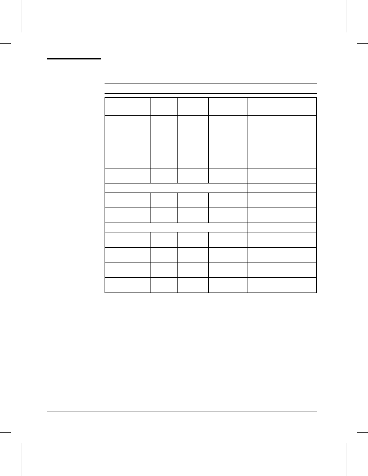
Table 1-1 Printer Features . . . . . . . . . . . . . . . . . . . . . . . 1-3
Table 1-2 Paper Capacitie s and Size s . . . . . . . . . . . . . . . . . . 1-4
Table 1-3 Printer Dimensions . . . . . . . . . . . . . . . . . . . . . . 1-6
Table 1-4 Electrical Specifications . . . . . . . . . . . . . . . . . . . 1-6
Table 1-5 Acoustic Emissions . . . . . . . . . . . . . . . . . . . . . . 1-7
Table 1-6 Related Documentation . . . . . . . . . . . . . . . . . . . . 1-19
Table 2-1 Printer and Toner Cartridge Environmental Conditions . . 2-4
Table 3-1 Indicator Lights . . . . . . . . . . . . . . . . . . . . . . . . 3-4
Table 3-2 Control Panel Keys . . . . . . . . . . . . . . . . . . . . . . 3-5
Table 3-3 Settings and Defaults . . . . . . . . . . . . . . . . . . . . . 3-6
Table 3-4 Control Panel Menu Map . . . . . . . . . . . . . . . . . . 3-7
Table 3-5 Printing Menu Items . . . . . . . . . . . . . . . . . . . . . 3-8
Table 3-6 PCL Menu Items . . . . . . . . . . . . . . . . . . . . . . . 3-9
Table 3-7 Job Menu Items . . . . . . . . . . . . . . . . . . . . . . . . 3-10
Table 3-8 Configuration Menu Items . . . . . . . . . . . . . . . . . . 3-11
Table 3-9 Memory Configurat io n Items . . . . . . . . . . . . . . . . 3-12
Table 3-10 Parallel Menu Items . . . . . . . . . . . . . . . . . . . . . 3-13
Table 3-11 Test Menu Items . . . . . . . . . . . . . . . . . . . . . . . 3-14
Table 3-12 Other Service Menu Items . . . . . . . . . . . . . . . . . . 3-18
Table 3-13 Menu of Resets . . . . . . . . . . . . . . . . . . . . . . . . 3-24
Table 5-1 Clutches and Sensors . . . . . . . . . . . . . . . . . . . . . 5-26
Table 7-1 Status Messages . . . . . . . . . . . . . . . . . . . . . . . 7-6
Table 7-1 Status Messages — continued . . . . . . . . . . . . . . . . 7-7
Table 7-1 Status Messages — continued . . . . . . . . . . . . . . . . 7-8
Table 7-1 Status Messages — continued . . . . . . . . . . . . . . . . 7-9
Table 7-1 Status Messages — continued . . . . . . . . . . . . . . . . 7-10
Table 7-2 Service and Error Messages . . . . . . . . . . . . . . . . . 7-11
Table 7-2 Service and Error Messages — continued . . . . . . . . . . 7-12
Table 7-2 Service and Error Messages — continued . . . . . . . . . . 7-13
Table 7-2 Service and Error Messages — continued . . . . . . . . . . 7-14
Table 7-2 Clearable Warning Mes sage s . . . . . . . . . . . . . . . . 7-15
Table 7-4 Blank (White) Page . . . . . . . . . . . . . . . . . . . . . . 7-21
Table 7-5 Black Page . . . . . . . . . . . . . . . . . . . . . . . . . . 7-22
Table 7-6 Faded Print . . . . . . . . . . . . . . . . . . . . . . . . . . 7-23
Table 7-7 White Stripes (parallel to path) . . . . . . . . . . . . . . . 7-24
Table 7-8 Black Lines (perpendic ular to path) . . . . . . . . . . . . . 7-24
Table 7-9 Black Lines (parallel to pat h) . . . . . . . . . . . . . . . . 7-25
Table 7-10 Repetitive Defects . . . . . . . . . . . . . . . . . . . . . . . 7-25
Table 7-11 Bubble Print . . . . . . . . . . . . . . . . . . . . . . . . . . 7-26
Table 7-12 Dropout . . . . . . . . . . . . . . . . . . . . . . . . . . . . 7-26
Table 7-13 Character Voids . . . . . . . . . . . . . . . . . . . . . . . . 7-27
Table 7-14 Background Scatter (or Lead ing Ed ge Halo) . . . . . . . . 7-28
Table 7-15 Partial Blank Page . . . . . . . . . . . . . . . . . . . . . . 7-28
v
Page 8

Table 7-16 Faulty Registration . . . . . . . . . . . . . . . . . . . . . . 7-29
Table 7-17 Smeared Print . . . . . . . . . . . . . . . . . . . . . . . . 7-30
Table 7-18 Compressed Print . . . . . . . . . . . . . . . . . . . . . . 7-30
Table 7-19 Image Skew . . . . . . . . . . . . . . . . . . . . . . . . . . 7-30
Table 7-20 High Voltage System Checks . . . . . . . . . . . . . . . . 7-34
Table 7-21 Causes of Paper Curl . . . . . . . . . . . . . . . . . . . . . 7-35
Table 8-1 Accessories and Supplies . . . . . . . . . . . . . . . . . . . 8-5
Table 8-1 Accessories and Supplies - continued . . . . . . . . . . . . 8-6
Table 8-A Common Fasteners Used in the Printer . . . . . . . . . . . 8-7
Table 8-A Common Fasteners Used in the Printer - continued . . . . 8-8
Table 8-B Replaceable Cables . . . . . . . . . . . . . . . . . . . . . . 8-8
Table 8-2 Covers and Doors . . . . . . . . . . . . . . . . . . . . . . . 8-11
Table 8-3 Foot Assemblies . . . . . . . . . . . . . . . . . . . . . . . 8-13
Table 8-4 Front Door Components (1 of 2) . . . . . . . . . . . . . . . 8-15
Table 8-5 Front Door Components (2 of 2) . . . . . . . . . . . . . . . 8-17
Table 8-6 Output Components . . . . . . . . . . . . . . . . . . . . . 8-19
Table 8-7 Internal Components (1 of 4) . . . . . . . . . . . . . . . . 8-21
Table 8-8 Internal Components (2 of 4) . . . . . . . . . . . . . . . . 8-23
Table 8-9 Internal Components (3 of 4) . . . . . . . . . . . . . . . . 8-25
Table 8-10 Internal Components (4 of 4) . . . . . . . . . . . . . . . . 8-27
Table 8-11 Card Cage Assembly . . . . . . . . . . . . . . . . . . . . . 8-29
Table 8-12 Optional Lower Cassette Assembly . . . . . . . . . . . . . 8-30
Table B-1 Novell NetWare Frame Types . . . . . . . . . . . . . . . . B-6
vi
Page 9

Product Information
Chapter Contents
Printe r Feature s . . . . . . . . . . . . . . . . . . . . . . . . . . . . . . 1-3
Paper Capacities and Size s . . . . . . . . . . . . . . . . . . . . . . . . . 1-4
Identification . . . . . . . . . . . . . . . . . . . . . . . . . . . . . . . . 1-5
Model and Serial Numbers . . . . . . . . . . . . . . . . . . . . . . . 1-5
Specifications . . . . . . . . . . . . . . . . . . . . . . . . . . . . . . . . 1-6
Media Selection Guidelines . . . . . . . . . . . . . . . . . . . . . . . . . 1-8
Paper . . . . . . . . . . . . . . . . . . . . . . . . . . . . . . . . . . . 1-8
Envelopes . . . . . . . . . . . . . . . . . . . . . . . . . . . . . . . . 1-8
Adhesive Labels . . . . . . . . . . . . . . . . . . . . . . . . . . . . . 1-9
Transparencies . . . . . . . . . . . . . . . . . . . . . . . . . . . . . . 1-9
Storing Print Media . . . . . . . . . . . . . . . . . . . . . . . . . . . 1-10
Shipping Print Medi a . . . . . . . . . . . . . . . . . . . . . . . . . . 1-10
Produc t Overv i ew . . . . . . . . . . . . . . . . . . . . . . . . . . . . . . 1-11
External Assembly Locations (1 of 2) . . . . . . . . . . . . . . . . . . 1-11
External Assembly Locations (2 of 2) . . . . . . . . . . . . . . . . . . 1-12
Front Door Assemblies . . . . . . . . . . . . . . . . . . . . . . . . . . 1-13
Internal Assembly Locations (1 of 2) . . . . . . . . . . . . . . . . . . 1-14
Internal Assembly Locations (2 of 2) . . . . . . . . . . . . . . . . . . 1-15
Service Approach . . . . . . . . . . . . . . . . . . . . . . . . . . . . . 1-16
Ordering Parts . . . . . . . . . . . . . . . . . . . . . . . . . . . . . 1-16
Phone numbers for the various sources are: . . . . . . . . . . . . . . 1-16
Exchange Program . . . . . . . . . . . . . . . . . . . . . . . . . . . 1-16
Consumables . . . . . . . . . . . . . . . . . . . . . . . . . . . . . . . 1-16
Toner Cartrid ge Life . . . . . . . . . . . . . . . . . . . . . . . . . . 1-17
Refilled Toner Cartridges . . . . . . . . . . . . . . . . . . . . . . . . 1-18
Recycling Toner Cart rid ges . . . . . . . . . . . . . . . . . . . . . . . 1-18
Related Documenta tion and Tr aining Media . . . . . . . . . . . . . . 1-19
1
Product Information 1-1
Page 10

Technical Assistance . . . . . . . . . . . . . . . . . . . . . . . . . . . 1-20
HP AUDIO-TIPS . . . . . . . . . . . . . . . . . . . . . . . . . . . . 1-20
HP FIRST . . . . . . . . . . . . . . . . . . . . . . . . . . . . . . . . 1-20
HP FIRST, U.S. . . . . . . . . . . . . . . . . . . . . . . . . . . . . . 1-20
HP FIRST, Europe . . . . . . . . . . . . . . . . . . . . . . . . . . . 1-20
HP CompuServe Forum . . . . . . . . . . . . . . . . . . . . . . . . . 1-21
North American Response Center (NARC) . . . . . . . . . . . . . . . 1-21
Other Areas . . . . . . . . . . . . . . . . . . . . . . . . . . . . . . . 1-21
Warranty Statement . . . . . . . . . . . . . . . . . . . . . . . . . . . . 1-22
Warranty . . . . . . . . . . . . . . . . . . . . . . . . . . . . . . . . . 1-22
One Year Return to HP Authorized Repair Station . . . . . . . . . . 1-22
Exclusions . . . . . . . . . . . . . . . . . . . . . . . . . . . . . . . . 1-22
1-2 Product Information
Page 11

Printer Features
1
Product
Information
Table 1-1 Printer Features
Features LaserJet 4V
Print Speed 16 ppm letter or A4
Text & Graphics Resolution 600 dpi; plus Resolution
Printer Language(s)
Standard
Optional
Monthly Usage (pages) Up to 35,000 Up to 35,000
Memory:
Standard
Optional (maximum)
Internal Typefaces 45 PCL 45 PCL, 35 PostScript
Cartridge Slots 00
Standard Interfaces Bi-Tronics Parallel (IEEE 1284) Bi-Tronics Parallel (IEEE 1284)
Power Control Power Save Mode Power Save Mode
Control Panel 8 Keys,
1
2
8 ppm ledger (11x17) or A3
Enhancement technology (REt)
Enhanced PCL 5
Adobe PostScript Level 2
4 Mbyte
68 Mbyte total
16 Character VFD Display
(C3141A)
16 ppm letter or A4
8 ppm ledger (11x17) or A3
600 dpi; plus Resolution
Enhancement technology (REt)
Enhanced PCL 5
Adobe PostScript Level 2
None
12 Mbyte
44 Mbyte total
JetDirect MIO
8 Keys,
16 Character VFD Display
LaserJet 4MV
(C3142A)
EconoMode (toner saving) Yes Yes
1
Printer memory is optimized with Memory Enhancement Technology (MEt).
2
SIMMS available for use include 1, 2, 4, 8, and 16 Mbtye Modules. See “Accessories & Supplies”
in Chapter 8 for option product numbers.
Product Information 1-3
Page 12
Paper Capacities and Sizes
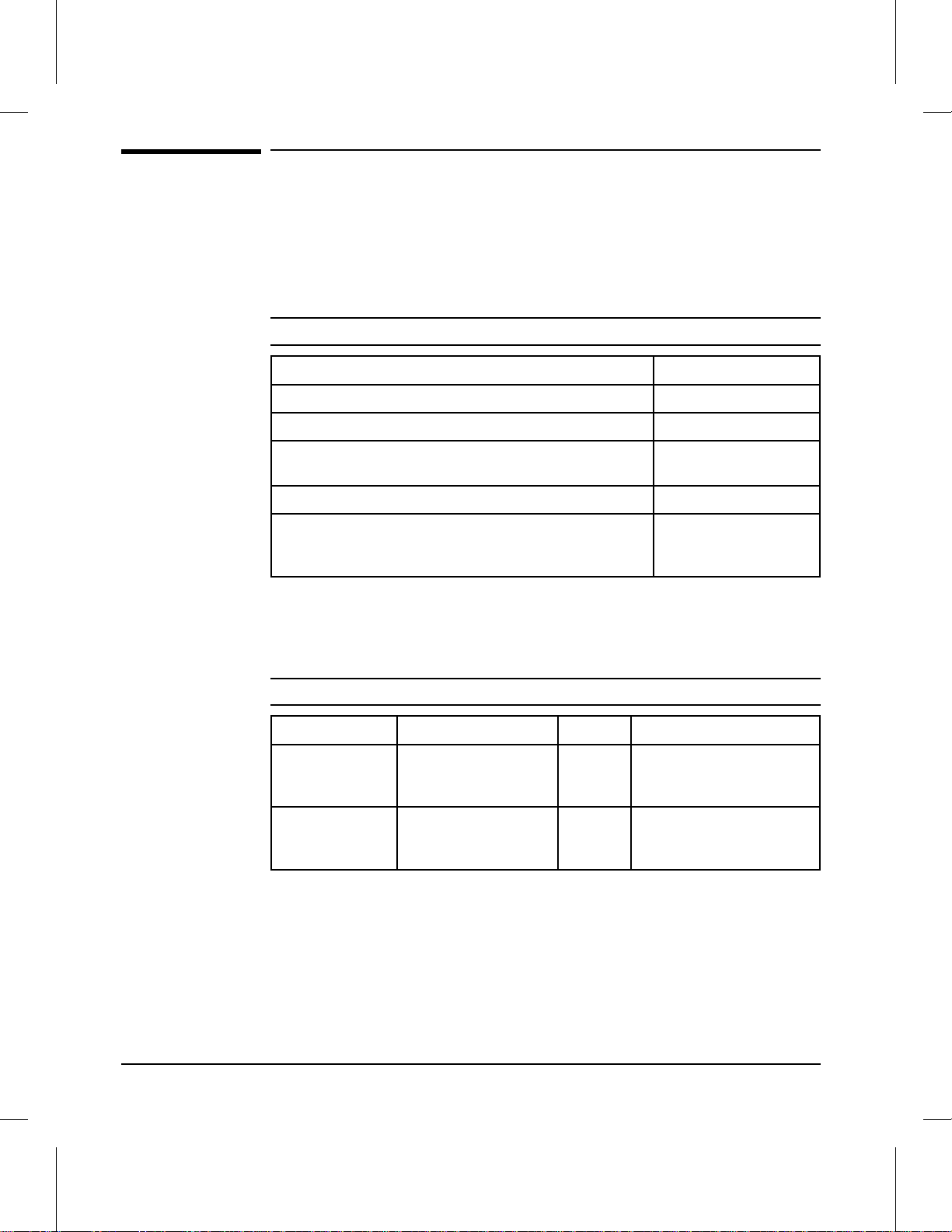
Table 1-2 Paper Capacities a nd Sizes
Name Product
Number
MP Tray N/A 100 sheets 17 to 28 pounds
Paper Output Bin N/A 250 sheets 17 to 28 pounds
Standard Cassettes
Letter/A4 C3160A 250 Sheets 17 to 28 pounds
11X17/A3 C3161A 250 Sheets 17 to 28 pounds
Optional Cassettes
Legal C3162A 250 Sheets 17 to 28 pounds
B4 C3163A 250 Sheets 17 to 28 pounds
B5 C3164A 250 Sheets 17 to 28 pounds
Lower Cassette C3760A 500 Sheets 17 to 28 pounds
Capacity Basis
Weight
(64 to 105 g/m2)
(64 to 105 g/m2)
(64 to 105 g/m2)
(64 to 105 g/m2)
(64 to 105 g/m2)
(64 to 105 g/m2)
(64 to 105 g/m2)
(64 to 105 g/m2)
Size Range
Maximum 11.7 x 17.7 in.
(297 x 450 mm)
Minimum 3.9 x 5.8 in.
(100 x 148 mm)
Standard sizes: A3, A4,
B/Ledger, B4, B5, Letter,
Legal, Executive
N/A
Selectable between letter
and A4
Selectable between ledger
and A3
Legal only
JIS B4 only
JIS B5 only
Adjustable for letter, legal,
ledger, A4, A3, and JIS B4
1-4 Product Information
Page 13
Identification
1
Product
Information
Model and Serial Numbers
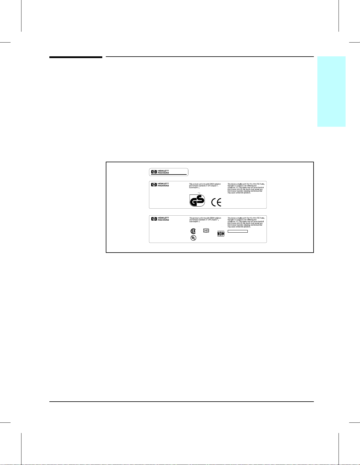
The model number and serial numbers are listed on ident if icat ion la bels
located on the rear of the prin t er . The model nu mbe r is alph a nume ric , suc h
as C3141A for the HP LaserJet 4V printer.
The serial number contains informatio n about the Count ry of Origin, t he
Revision Level, th e Produc tio n Co d e, and prod uct io n numbe r of the pri n ter.
The rear labels also contain power rating and regulatory informat ion as
shown in Figure 1-1.
Figure 1-1
C3141A
C3141A
RS5-8403
C3141A
RS5-8402
POWER RATING:
220-240V 50 Hz, 2.8A
2
geprüfte
Sicherheit
CE1
POWER RATING:
100-120V 50-60 Hz, 5.7A 127V
®
CE1
51742
LISTED
ITE
660F
®
HEWLETT-PACKARD
11311 CHINDEN BLVD.
BOISE, IDAHO 83714 U.S.A.
MANUFACTURED:
XXXXXXXX
SERIAL NO.:
Made in Japan
HEWLETT-PACKARD
11311 CHINDEN BLVD.
BOISE, IDAHO 83714 U.S.A.
MANUFACTURED:
XXXXXXXX
SERIAL NO.:
Made in Japan
Sample Model and Serial Number Labels
60 Hz, 5.7A
FCC ID: B94C3141A
C3141A
Product Information 1-5
Page 14
Specifications
This section contains inf ormat io n on phy sic al and electr ical char ac t eristics
of the printer. For information on printer site requirements (such as
operating temperature and humid it y, ventilation, et c.) see Chapter 2.
Table 1-3 Pri nter Dimensions
Width 18 in. (46 cm)
Depth 23 in. (59 cm)
Description Dimension
Height (standard)
(with Optional Lowe r Cassett e)
Weight (with toner cartridge) 52 lbs. (23.5 kg)
Toner cartridge weight* 70.5 oz. (2000 g) ful l
* Some quantity of toner will reside in the waste toner area of a toner cartridge when the toner
supply is exhausted. Therefore, using toner cartridge weight may be an unreliable indication of
remaining toner supply.
Table 1-4 Electrical Specifications
Volts Freq Amps Watts (typical)
120 V ac ± 10%
100 V ac ± 10%
220 V ac ± 10%
240Vac ± 10%
*Operating current requirements.
50/60 Hz ± 2 Hz
50/60 Hz ± 2 Hz
50/60 Hz ± 2 Hz
50/60 Hz ± 2 Hz
12.4 @
120v
5.4 @
220v
12 in. (30 cm)
17.3 in. (44 cm)
56.4 oz. (1600 g)
empty
printing = 385
standby = 115
Power Save Mode = 31
printing = 400
standby = 120
Power Save Mode = 3 8
1-6 Product Information
Page 15

Table 1-5
1
Product
Information
Acoustic Emissions
Operation position (per ISO 9296)
Printing L
Standby
Power Save
dB(A) 55 db
PA
dB(A)
L
PA
L
dB(A)
PA
Bystander 1m (per ISO 9296)
Printing L
Standby
Power Save
dB(A) 51 db
PA
dB(A)
L
PA
L
dB(A)
PA
Sound Po wer (per ISO 9296)
Printing L
Standby
Power S ave
WAD
L
WAD
L
WAD
38 db
33 db
34 db
29 db
6.6 bels (A)
4.9 bels (A)
4.4 bels (A)
Product Information 1-7
Page 16

Media Selection Guidelines
NOTE
More detailed specifications are in the HP LaserJet Printer Family Paper
Specification Guide, HP Part No. 5002-1801 (See “R elate d Docum en t at ion
and Training Media” later in this chapter).
Paper
To achieve the bes t po ssible p rint quality and avoid pape r jams , follow these
guidelines for selecting paper:
• Use only copier grade paper that meets all specificat io ns in the pap er
specification guide. Avoid paper with embossed lettering, perforations, or
texture that is too smooth or too rough.
• Colored paper should be of the same high quality as white photocopy paper.
The pigments must withstand the fusing temperature of 392°
0.1 second with out det er ioration. Do not use pap er with a colo r ed co at in g
that was added after the paper was produced.
F (200° C) for
• Pre-printed forms must be print ed wit h no n- flam mable , heat- resis t ant inks
that do not melt, vaporize, or release hazardous emissions when subjected
to the fusing temperature of 392° F (200° C) for 0.1 second.
•
A small sample of a new print media should be tested before purchasing
large quantities.
Envelopes
CAUTION To prevent severe printer damage, do not use envelopes having windows,
clasps, snaps, or synthetic materials.
Envelopes can be print ed only from the MP Tray. Choose envelope s that
are well-constructed. They shou ld lay flat and be shar p ly c rease d. They
should not be wrinkled, nicked, or otherwise damaged. Envelope adhesive
must be compatible with the heat and pressure of the fusing process.
1-8 Product Information
Page 17

Adhesive Labels
1
Product
Information
Use the following guidelines when selecting labels:
CAUTION
This printer does not support use of labels with any exposed spaces.
Previous LaserJet family printers could safely print on label stock with
exposed spaces running lengthwise down the sheet.
Do not attempt to print on label she ets af ter any of the labels have be en
removed from the sheet . Damage t o the pri n ter may res ult .
• Labels must be arranged on the carrier sheet so that there are no exposed
spaces on the sheet. Using label stock with spaces between rows or columns
of labels can often result in labels peeling off during printing, causing
serious jamming and possible printer damage.
• The top sheet (printing surface) must be of copier quality and provide good
toner adhesion.
• The carrier sheet (bac k ing she et) mus t be c omp at ible wit h t he tem per at u r es
and pressure of the fusing process, and must be coat ed for easy rele ase of
the top sheet.
• The adhesive must be stable at the 392° F (200° C) temperatures
encountered for 0.1 second in the fusing process, and must not produce
emissions that exceed exposur e le ve ls or thre s hold limits establis he d by
OSHA and other safety agencies. Adhesives must not come into direct
contact with any part of the printer.
NOTE The MP Tray is recommended for printing adhesive labels.
A wide selection of suitable labels is available through Hewle t t-Pa ckar d. A
list of available sizes is located in the HP LaserJet Printer Family Paper
Specification Guide, HP Part No. 5002-1801.
Transparencies
Overhead transparencies used in HP LaserJe t printers must be able to
withstand the 392° F (200° C) temperatures encountered in the printer’s
fusing process for 0.1 second. Suitable transparency film is available
through Hewlett-Packard. Refer to the HP LaserJet Printer Family Paper
Specification Guide, HP Part No. 5002-1801 for details.
NOTE The MP Tray is recommended for printing transparencies.
Product Information 1-9
Page 18

Storing Print Media
Follow these guidelines when stacking and storing print med ia:
• Store paper in its ream wrapper until ready to use.
• DO NOT store cartons or reams directly on the floor where they will absorb
a higher moisture content. Instead , place cart ons on a pallet or on shelv es.
• DO NOT store individual reams in a manner that causes them to curl or
warp along the edges.
• Re-wrap partially used packages of media before storing.
• DO NOT stack more than six cartons on top of each other.
• Stack each carton upright and squarely on top of the one underneath.
• DO NOT place anything on top of media, regard less of whet he r the paper is
packaged or unpackaged.
• Store envelopes in a protective box to avoid damaging the envelope edges.
• Keep stored media away from temperature and humidity extremes.
• DO NOT store printed documents in vinyl folders (which may contain
plasticizers) or expose the docu ment s to petrole um base d solvent s.
Shipping Print Media
When shipping prin t media th rough dif ferent envir onm ents, plastic wrap all
cartons on the shipping palle t. When shipp ing media across bod ies of
water, wrap individual car ton s as well. Pac kagin g mus t protect the medi a
from physical damage.
1-10 Product Information
Page 19
Product Overview
1
Product
Information
External Assembly Locations (1 of 2)
32
1
4
12
11
10
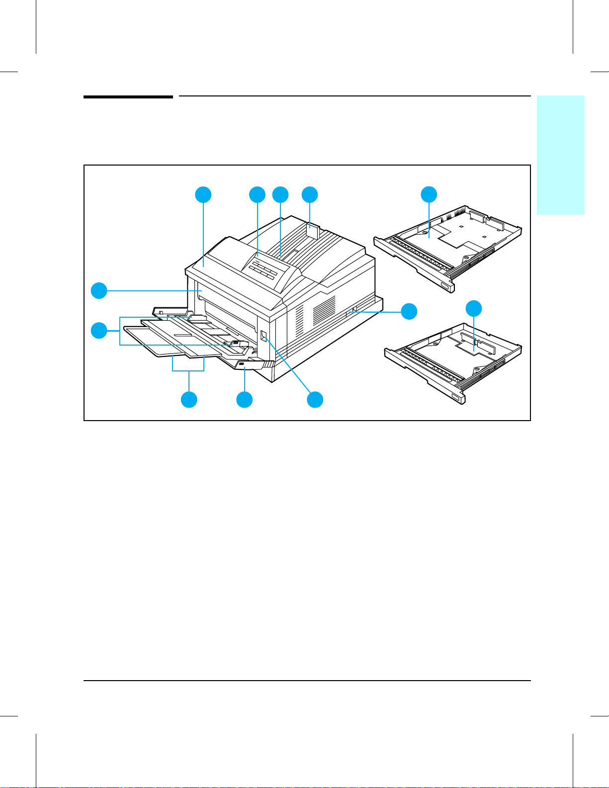
Figure 1-2 Front and Right Side View with MP Tray Ope n
1 Front Cover
2 Control Panel
3 Output Bin
4 Adjustable Paper Stop
5 250 sheet ledger (11x17) or A3 Paper Cassette
6 ON/OFF Switch
7 250 sheet Letter or A4 Paper Cassette
8 Front Cover Re lease Button
9 Multipurpose (MP) Tray
10 MP Tray Extension
11 MP Tray Paper Width Guides
12 Fuser Door
9
8
5
6
7
Product Information 1-11
Page 20
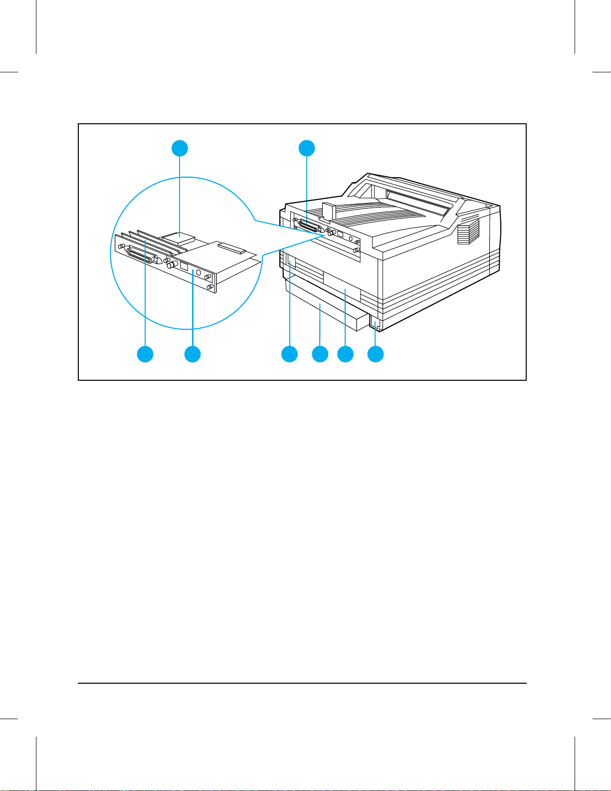
External Assembly Locations (2 of 2)
1
3 4
Figure 1-3 Rear and Left Side View
1 Optional 42.8 Mbyte Disk Accessory Location
2 Parallel Bi-Tronic s Int e rfa c e
3 SIMM Slots
4 Multiple I/O (MIO) slot
5 Power Supply Connector
6 Dust Cover for 250 sheet ledger (11x17) or A3 Paper Cas sett e
7 Serial Number Plate
8 Optional Universal Lower Cassette Connector Access
2
5678
1-12 Product Information
Page 21
Front Do or As sembli e s
1
Product
Information
1
2
3
4
5
6
7
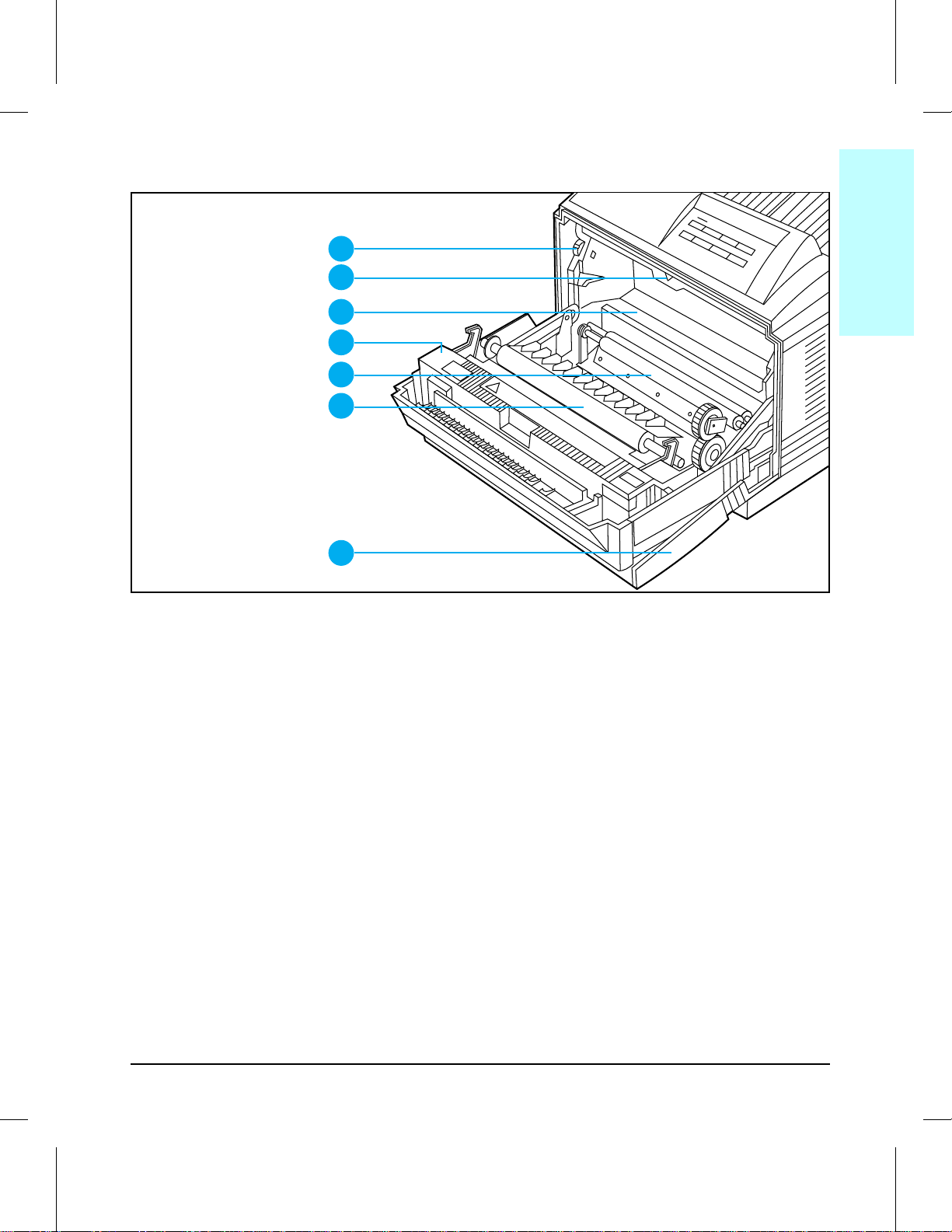
Figure 1-4 Front View with Front Cover Open (wit h toner cartridge re m oved)
1ASYDOOR
1 Print Density Dial
2 Arrow guide for installing toner cartridge in printer
3 Toner cartridge cavity
4 Fusing Assembly
5 Registratio n Roller
6 Transfer Roller
7 Multipurpose (MP) Tray
Product Information 1-13
Page 22
Internal Assembly Locations (1 of 2)
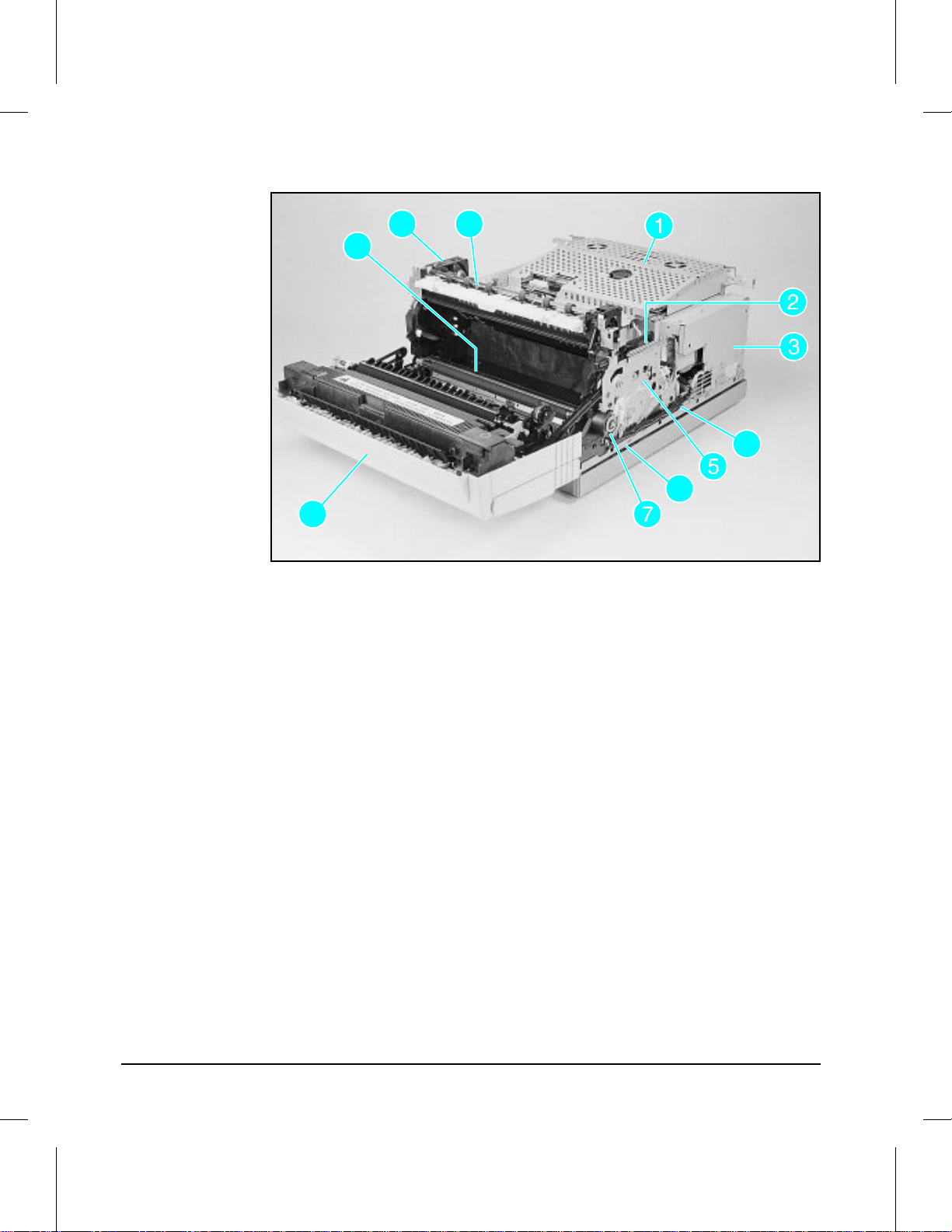
Figure 1-5I
Internal Assembly Locat ions (1 of 2)
1 Card Cage Assembly
2 Main Motor
3 Power Supply Unit
4 Fusing Assembly Cable
5 Main Drive Assembly
6 Cassette Pickup Roller Clutch
7 Registration Roller Clutch
8 Front Door
9 Cassette Pickup Roller (under plate)
10 Exhaust Fan (FM1)
11 Delivery Assembly
1-14 Product Information
Page 23
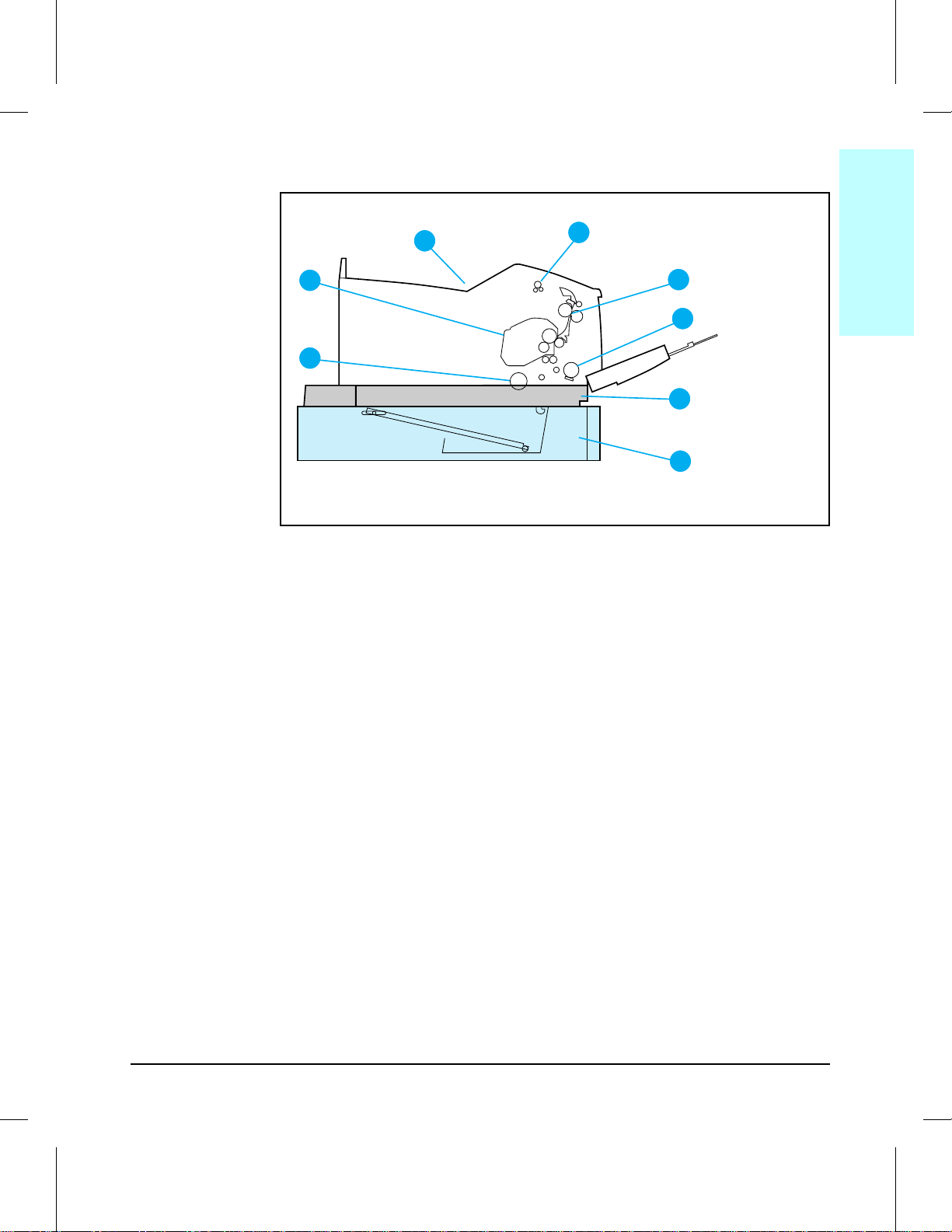
Figure 1-6
1
Product
Information
1ASSYSEC
Internal Assembly Locati ons (2 of 2)
1
2
8
7
Internal Assembly Loc ati ons (2 of 2)
1 Output Bin
2 Delivery Assembly
3 Fusing Rollers
4 Transfer Roller
5 Standard Paper Casse tt e
6 Optional Lower Paper Cassette
7 Cassette Pickup Roller
8 Toner Cartridge
3
4
5
6
Product Information 1-15
Page 24

Service Approach
Repair of the printer normally beg ins wit h us e of the printer ’s int ern al
diagnostics in conjunction with the troubleshooting procedures in Chapter 7.
Once a faulty part is located, repair is generally accomp lished by assembly
level replacement of Field Replaceable Unit s (FRUs). Some mechanic al
assemblies may be repaired at the subassembly level. PCA compone nt
replacement is not supported by Hewlett-Packard.
Ordering Parts
Field replaceable part numbers are found in Chap ter 8 of this manual.
Replacement parts may be ordered from HP’s Service Materials
Organization (SMO), or Support Materials Europe (SME).
Phone numbers for the various sources are:
• SMO (Service Materials Organization)
1-800-227-8164 (U.S. only)
• SME (Support Materials Europe)
(49 7031) 142253
• HP’s Distribution Center (HPD)
1-303-353-7650
Exchange Program
HP offers remanufactured assemblies for some parts. These are ident ified
in Chapter 8 and can be ordered through Parts Direct Ordering (PDO), or
Support Materials Europe (SME).
Consumables
The printer has no consumables other than the toner cart ridge, which may
be ordered directly from Hewlett-Packard. Refer to Chapter 8 for ordering
information.
1-16 Product Information
Page 25
Figure 1-7
1
Product
Information
Toner Cartridge Life
The toner cartridge (C3900A) is designed to simplify replacement of the
major “consumable” parts. The toner cartridge contains the printing
mechanism and a supply of toner.
At 5% page coverage, a toner cartrid ge will pri n t approximat ely 7500 p ages
(see Figure 1-7).
Sample 5% Page Coverage
When regularly printin g pag es wit h less cover age , such as sho rt memo s, a
toner cartridge should print more th an 7 500 page s . However, the cart rid ge
may print less than 7500 pages if routinely printing very dense print.
NOTE For best results, always use a toner cartrid ge be fore the expir at io n d at e
stamped on the toner cartridge box.
Product Information 1-17
Page 26

Refilled Toner Cartridges
While Hewlett-Pack ar d does not prohibit the use of refilled toner car trid ge s
during the warranty period or while under a maintenance contract, their
use is not recommended for the following reasons:
• Repairs resulting from the use of refilled tone r car trid ges ar e not covered
under the Hewlett-Packard warranty or maintenance contract.
•
Hewlett-Packard has no control or process to ensure that a refilled toner
cartridge functions at th e high lev el of reliability of a new HP LaserJet
toner cartridge. Hewlett-Packard also cannot predict what the long term
reliability effect on the printer is from using different toner formulations
found in refilled cartrid ges.
• The print quality of HP LaserJet toner cartridges influences the customer’s
perception of the printer. Hewlett-Packard has no control over the actual
print quality of a refilled toner cartridge.
Recycling Toner Cartridges
In order to reduce waste, Hewlett -Pac kar d ut ilize s a recycling progr am fo r
used toner cartridges. Cartridge components that do not wear out are
recycled. Plastics and other materials are recycled. Hewlett-Packard pays
the shipping costs from the user to the recycling plant. For each cartrid ge
returned, HP don a te s one U .S. d ollar t o be shared by the Nature
Conservancy and the National Wildlife Federation. To join this recycling
effort, follow the instructions inside the toner cartridge box.
1-18 Product Information
Page 27

Related Documentation and Training Media
1
Product
Information
Table 1-6 lists where to order related documentation. See “Ordering Parts”
earlier in this chapter.
Table 1-6 Related Documentation
Description Part Number SMO SME HPD
HP LaserJet Family Quick Ref er enc e
Service Guide
HP LaserJet 4V and 4MV Printers
User’s Manual
HP PCL5 Printer Langua ge Technic al
Reference Information Package
HP LaserJet Printer Family Paper
Specifications Guid e
Introduction to Netw ork Printing,
Network Printi ng for the Enterprise,
LaserJet Basic Hardwar e Training Course
Solutions Connectivity Guide
(Ava il abl e f r o m L D C 1-800-544-9976)
Specific Application Drivers
1
Shipped with printer. (English version part number is shown. Other translations are available
see your local HP Sales Office.)
1
Book 5961-0649 X X
Video 5961-0650 X X
5961-0531 X X
C3141-90901 X X
5961-0601 X X
5002-1801 X
5961-0880 X X
5962-8536E
X
Product Information 1-19
Page 28

Technical Assist ance
HP ASAP (Automated Support Access Program) provid es free technica l
support infor mat io n 24 h our s a da y , 7 days a week. The ASA P syst e m
includes HP AUDIO-TIPS and HP FIRST, both explained below . The ASAP
service requires a touchtone phone.
HP AUDIO-TIPS
HP AUDIO-TIPS is an interactive voice response system providing
prerecorded answers to the most frequently asked questions by HP LaserJet
printer users. Helpful “Sys t em Map s” t o the HP AU DIO- TIPS r ecor din gs
are available by fax through HP FIRST.
HP FIRST
HP FIRST (Fax Information Retrieval Support Technology) is a phone-in
fax service providing technical informat ion f or HP LaserJe t users as well as
service personnel. Receiving a fax requires a group 3 facsimile mac hine or
fax card. Service related information includes:
• Service notes (HP Authorize d deale r s)
• Application notes
• Product Data Sheets
• Material Safety Data Sheets (MSDS)
•
Typeface and accessory information
• Printer support software information
•
Toner information
• Driver request form and Software Matrix.
HP FIRST, U.S.
Call the HP ASAP system (1-800-333-1917) and follow the voice prompt s to
enter HP FIRST.
HP FIRST, Europe
Call HP FIRST at one of the following numbers:
U.K., 0800-96-02-71 Netherlands, 06-0222420
Belgium (Dutch), 078-111906 Germany, 0130-810061
Switzerland (German), 155-1527 Austria, 0660-8128
For English service outside the above countries, (31) 20-681-5792.
1-20 Product Information
Page 29

HP CompuServe Forum
1
Product
Information
CompuServe members can download a variety of support materials
including product data sheets, software application notes, and printer
drivers for many popular software app licat ion s. Membe rs may also post and
reply to questions in an interact ive form at . To access the HP Fo rum, type
GO HP at any prompt. For more information, or to join CompuServe, call
1-800-524-3388.
North American Response Center (NAR C)
The North American Response Center (NARC) is available for technical
support to assist service technicians. The NARC can be reached at
1-800-544-9976 between 7:00 A.M. and 6:00 P.M. Mountain Standar d Time,
Monday, Tuesday, Thursday and Fr iday. On Wedne sdays the office clos es
at 4:00 P.M.
Other Areas
Outside of North Ame ric a and Eur op e, co ntac t your local HP sale s offic e for
assistance in obtaining technical support .
Product Information 1-21
Page 30

Warranty Statement
Warranty
This warranty give s spec ific legal rights. There may also be other rights
which vary from area to area. Refer to Appendix E in the User’s Manual for
further warranty inf ormation.
One Year Return to HP Authorized Repair Station
Hewlett-Packar d war ra n ts th e LaserJet 4V/ 4MV pr int er against de fects in
materials and workmanship for a period of one year from receipt by the
customer. During the warranty p er iod, HP will, at its option , either repair
or replace products which prove to be defective.
NOTE
User maintenance components are not covered under the
HP LaserJet 4V/4MV printer factory warranty. A separate maintenance
agreement may be written to cover these components.
Exclusions
The warranty on printers shall not apply to defects resulti n g from:
• Improper or inadequate maintenance by customer.
• Customer supplied software or interfacing.
• Unauthorized modification or misuse.
• Operation outside of the environmental specifications for the product.
• Operation of non-supported printing media.
• Duty cycle abuse maximum (printing more than the equivalent of 35,000
single-sided page s p er mon th) .
• Operating the printer from a mechanical switchbox wit hout a design ated
surge protector.
• Improper site preparation and maintenance.
• Use of non-HP toner cartridges (see the following explanation), SIMM
memory boards, or interface boards.
The use of non-He wle t t-Packard toner cartridges doe s not aff ec t eithe r th e
warranty or any maintenance contrac t p urchas ed from HP. However, if an
HP LaserJet printer failure or if printer damage is found to be directly
attributa ble t o the use o f any non- HP product, the r e pair will not be covered
under the warranty or HP main ten anc e contr ac t. Hewlet t-Packard cannot
recommend use of non-HP cartridges, either new or remanufactured,
because they are not HP products and HP cannot influence or control their
quality.
1-22 Product Information
Page 31

Site Requirements
Chapter Contents
Operating Environment . . . . . . . . . . . . . . . . . . . . . . . . . . 2-3
Space Requirements . . . . . . . . . . . . . . . . . . . . . . . . . . . . 2-4
Environmental Requirements . . . . . . . . . . . . . . . . . . . . . . . 2-4
2
Site Requirements 2-1
Page 32

2-2 Site Requirements
Page 33

Operating Environment
2
Site
Requirements
The environmental specifications (listed in the “Specifications” section of
Chapter 1) must be maintained to ensur e the proper op eratio n of this
printer. Consider the following points before installing the print er:
• Install in a well-vent ilated, dust-free area.
• Install on a hard, flat and continuous surface, with all four printer feet
level. Do not install on carp et or other soft sur f ac es.
• Ensure adequate power is supplied . Printer power requir ement s are listed
under “Specifications,” in Chapter 1.
• Install where there is stable temperature and humidity, away from water
sources, humidifie rs, air cond it io ne r s, r efri g er at ors , or othe r maj or
appliances.
• Install away from direct sunlight, open flames, or ammonia fumes. If the
printer is placed near a window, make sur e t he wind ow has a cu rt ain or
blind to block any direct sunlight.
• Install with enough space around the printer for proper access and
ventilation (see Figure 2-1).
• Install printer away from the direct flow of exhaust from air ventilation
systems.
Site Requirements 2-3
Page 34

Space Requirements
49.2 in (1250mm)
3.94 in (100mm)
3.35 in (85mm)
Optional Lower Cassette
Figure 2-1 Printer Space Requirements
3.54 in
(90mm)
25.35 in (644mm)
(340mm)
13.38 in
(440mm)
17.3 in
Environmental Req uirements
Keep the printer within the following environmental conditions for optimum
performance.
Table 2-1
2-4 Site Requirements
Printer and Toner Cartridge Environm ental Condi tions
Temperature 10° to 32.5° C
Humidity 20 to 80% RH
Item Operating Storage
0° to 40° C
(50° to 90.5° F)
(32° to 105° F)
10 to 95% RH
(with no condensation)
(with no condensation)
Page 35

Operating Overview
Chapter Contents
Using the Control Panel . . . . . . . . . . . . . . . . . . . . . . . . . . 3-3
Control Panel Layout . . . . . . . . . . . . . . . . . . . . . . . . . . 3-3
Indicator Lights . . . . . . . . . . . . . . . . . . . . . . . . . . . . . 3-4
Control Panel Keys . . . . . . . . . . . . . . . . . . . . . . . . . . . . 3-4
Settings and Defaults . . . . . . . . . . . . . . . . . . . . . . . . . . 3-6
Setting the Display Language . . . . . . . . . . . . . . . . . . . . . . 3-6
Control Panel Menus . . . . . . . . . . . . . . . . . . . . . . . . . . . 3-7
Printing Menu . . . . . . . . . . . . . . . . . . . . . . . . . . . . . . 3-8
PCL Menu . . . . . . . . . . . . . . . . . . . . . . . . . . . . . . . . 3-9
Job Menu . . . . . . . . . . . . . . . . . . . . . . . . . . . . . . . . . 3-10
Configuration Menu . . . . . . . . . . . . . . . . . . . . . . . . . . . 3-11
Memory Configur at ion Men u . . . . . . . . . . . . . . . . . . . . . . 3-12
Parallel Menu . . . . . . . . . . . . . . . . . . . . . . . . . . . . . . 3-13
Test Menu . . . . . . . . . . . . . . . . . . . . . . . . . . . . . . . . 3-14
Service Mode . . . . . . . . . . . . . . . . . . . . . . . . . . . . . . . . 3-15
Power Save . . . . . . . . . . . . . . . . . . . . . . . . . . . . . . . . 3-15
Setting the Page Count and Serial Number . . . . . . . . . . . . . . 3-17
Setting the Cold Reset Default Paper Size . . . . . . . . . . . . . . . 3-18
Other Service Mode Items . . . . . . . . . . . . . . . . . . . . . . . . 3-18
Testing the Printer . . . . . . . . . . . . . . . . . . . . . . . . . . . . . 3-19
Printing a Self Test Page . . . . . . . . . . . . . . . . . . . . . . . . 3-19
Understanding the Self Te st Pr int out . . . . . . . . . . . . . . . . . . 3-20
Self Test Printout Key . . . . . . . . . . . . . . . . . . . . . . . . . . 3-20
Engine Test . . . . . . . . . . . . . . . . . . . . . . . . . . . . . . . 3-22
Resetting the Printer . . . . . . . . . . . . . . . . . . . . . . . . . . . . 3-23
Simple Reset . . . . . . . . . . . . . . . . . . . . . . . . . . . . . . . 3-23
Cold Re se t . . . . . . . . . . . . . . . . . . . . . . . . . . . . . . . . 3-23
Menu of Resets . . . . . . . . . . . . . . . . . . . . . . . . . . . . . . 3-24
3
Operating Overview 3-1
Page 36

3-2 Operating Overview
Page 37

Figure 3-1
3
Operating
Overview
Using the Control Panel
Control Panel Layout
The control panel consists of a 16-charac t er disp lay pane l, t hree indicator
lights, and eight keys, three of which have alternate functio ns.
Ready
On Line Form Feed MP Paper Size Enter
Menu Item
Shift Reset Continue
+
-
Control Panel Layout
Operating Overview 3-3
Page 38

Indicator Lights
The control panel indicator lights are described in the following table. The
column labeled “Do this:” includes an action only whe n an ac tion is
required.
Table 3-1
When this
indicator:
Ready On
On Line On
Form Feed On
Looks like this: It means this: Do this:
Flashing
Off
Flashing
Off
Flashing
Off
Indicator Lights
Ready to print.
Print job in progress.
Not ready to print.
Ready to receive data.
Going off line.
Printer is off line. Access other ke y s or pres s [On Line]
Data still in print buffer.
Buffered data is
printing.
No buffered data in
printer.
Let job finish printing.
See display panel message.
to place printer back on line .
Take printer off line; press
[Form]Feed]; press [On Line] to place
printer back on line.
Control Panel Keys
You must take the printer off line to use con trol pane l keys , excep t for the
MP Paper Size and keys related to its operatio n.
Each key in the top row has a single function. Three keys in the bottom row
have more than one function. The primary function name of each key
appears above the key. The alternate function name of each key appears
below the key. These alternate function names are color-coded to match the
[Shift] key, which you must hold down while selecting an alternate function.
You can rapidly scroll through some selections by holding down the [+/-] key.
3-4 Operating Overview
Page 39

Table 3-2
3
Operating
Overview
Key Explanation
[On Line] Switches the state of communicati on betw een comput er and printer either on
[Form Feed] Prints any data remaining in the page buf fer. Does not send a b l ank sheet of
[MP Paper Size] Only activ e when MP Tray is set to ca sset te (s elec t MP TRAY=CASS in the
[Enter] Saves a sel ect ed co ntr ol panel key setting. An asterisk (*) appears next to the
[Shift] Accesses color coded alternate functions of bot tom -ro w cont rol panel k eys.
[Menu] Cycles through menus, returning to 00 OFFLINE at the end of the cycle unless a
Control Panel Keys
(on line) or off (off line). For the printer to receive data, both the On Lin e an d
Ready indicator lights must be lit.
paper through the printer.
Configuration Menu). Selects size of paper loaded in MP Tra y. Pressing [Enter]
saves your se lecti on.
saved selection, indicating that it is now the default. Default settings remain in
place when the printer is reset or switched OFF.
Hold down while pressing an assoc iated k ey.
problem is encounter ed. When an option is added to the printer (P os t Script, f or
example), a menu for that option appears in the sequence (see “Control P an el
Menus” in this chapter).
Reset
[Shift] + [Reset]
[Item] Cycles through the selected menu items. Menu items vary depending on
Continue
[Shift] + [Continue]
[+] or [-] Press [+] to step through menu items. Hold down [+] to scroll through items.
Resets the printer (displays 07 RESET). Clears the page and active I/O buffers
and makes the current cont rol panel values the defaults (see “Menu of Resets”
at the end of this chapter).
options installed and configur ation of other menu choices.
Allows the printer to resum e print i ng after a print er mes sage ( su ch as
20 MEM 0V ERFLOW) has placed it off line. Clears most printer messages (such
as manual f eed reques t s) and plac es the print er bac k on lin e .
Press or hold down [Shift] + [-] to move through items in reverse order.
Operating Overview 3-5
Page 40

Settings and Defaults
The printer makes most printing decisions based on either temporary
settings or permanent defaults.
NOTE
Table 3-3
Settings you send from software applications override printer d efaults .
Settings and Defaults
Setting or Default Explanation
Temporary setting A value set for the current print job by your software
application. For example , a request from your
software to print three copies i nstead of t he cont rol
panel default val ue of one co py is a temporary
setting. The printer continues to use the temporary
setting until you send another software request or
reset the print er.
Control panel defaul t A value you set at the control panel by selecting a
menu item, then pressing [Enter]. An asterisk
appears followi ng the item name to in dicat e that it is
now the defaul t. The printer retains this def aul t
when it is switched off.
Fac tory defaul t The value set for each menu ite m at the factory.
Factory defaults are marked with an asterisk in the
menu tables on the pages that follow.
Setting the Display Language
1 Press and hold [Enter] while powering on. Hold [Enter] until CONFIG
LANGUAGE appears.
2 Releas e [Enter]. 05 SELF TEST appears briefly. Wait for LANG=ENGLISH to
appear.
3 Click [+] repeatedly until the desired language appears.
4 Click [Enter] to save your choice . An asterisk (*) will appear beside your
language selection.
3-6 Operating Overview
Page 41

Control Panel Menus
3
Operating
Overview
Pressing [Menu] gives you access to the menus, one after another. Each
menu is described in a separate table in this sectio n. When option s (suc h as
the PostScript language) are inst alle d in the pri n ter , new menus or menu
items automatically ar e add ed in th e appropriat e menus .
Table 3-4 Cont rol Panel Menu Map
PRINTING MENU PCL MENU PS MENU JOB MENU CONFIG MENU MEM CONFIG
COPIES FONT SOURCE PRT PS ERRS RESOLUTION MP TRAY IO BUFFER HIGH SPEED SELF TEST
P APER FONT NUMBER JAM RECOVER PERSONALITY LOCK** IO SIZE ADV FNCTNS CONT SELF TEST
ORIENT ATION PITCH or
FORM SYM SET IO TIMEOUT AUTO CONT PCL MEM P CL DEMO PAGE
MANUAL FEED LOW TO NER PS MEM PS CONFIG P A GE
RET PS TYPEFA CE
ECONOMODE PS DEMO PAGE
You can change these menu items either from a software
application or from the control panel.
Shaded items appear when the PostScript option is installed.
Additional menu items may appear if options are installed (such as MIO cards).
* These items will appear if sufficient memory is available.
** The Lock function is only available if MP Tray = Cassette.
PT SIZE
PWR SAVE CLR WARN RESRCSAVE PCL TYPEFACE
You can change these menu items only from the control panel.
MENU*
PARALLEL MENU TEST MENU
LIST
LIST
To select a menu item:
1 Press [On Line] to take the printer off line.
2 Press [Menu] repeatedly until the menu you want app ear s .
3 Press [Item] repeatedly until the item you want appears.
4 Press [+] repeatedly (or hold down [+] to scroll) until the setting you want
appears.
5 Press [Enter] to save your selection. An asterisk appears next to your
selection, indicating that it is now the default.
6 Press [On Line] to place the printe r back on line.
Operating Overview 3-7
Page 42

Printing Menu
You can override or change any Print ing Menu set ting t hro ugh most
software applications. When you change a setting from the printer control
panel, the new setting becomes the printer default value.
Table 3-5 Printing Menu Items
Item Options Explanation
COPIES 1* to 999 Select any number from 1 to 999.
PAPER
ORIENTATION P*, L P means portrait
FORM 5 to 128 LINES
MANUAL FEED OFF*, ON Av ailab le only through MP Tra y. When Manual Feed i s
RET OFF, LIGHT, MEDIUM*, DARK Refines print quality by smoothing the fine gradations
ECONOMODE OFF*, ON EconoMode substantially reduces the amount of toner
*Factory default. **Factory default for 110V printers. ***Factory default for 220V printers.
LETTER**, LEGAL, A4***,
EXEC, 11x17, A3, JIS B 4,
JIS B5, CUSTOM, COM10,
MONARCH, C5, DL, B5,
JPOST, JPOSTD
(60** and 64***)
Sets default image size at which print er formats page
unless a software setti ng o v er rides i t.
Sets vertical spacing, from 5 to 128 lines, for default
paper size. Scrolls in increments of 1 line.
on and the MP Tray is empt y, the printer goes off lin e
when it receives a print job and displays MF FEED
paper size
a sheet in the MP Tray, the printer goes bac k on li n e
and prints the sheet.
along the angles and curves of the printed ima g e.
on the printed page; the resul t is similar to draf t mode
on some dot matrix printers.
or ME FEED
envelope size
. Whe n you place
3-8 Operating Overview
Page 43

PCL Menu
3
Operating
Overview
PCL Menu items allow you to choose the pr inter def ault font and symbo l
set. Printer Control Language (PCL) is HP print er languag e. You can also
change such PCL Menu items as the FONT SOURCE through your so ftware
application.
Table 3-6 PCL Menu Items
Item Options Explanation
FONT SOURCE I*
S
Mn
FONT NUMBER 0 to 999 The printer assigns a number to each typeface and lists them on the
PITCH
or
PT. SIZE
SYM SET ROMAN-8*
Range
Pitch:
10.00*
Point:
12.00*
Many others
Internal fonts*
Permanent soft f ont s
SIMM Module: n=s l ot n umber. Typef ac es stored in one of the f our
ROM SIMM slots ( M1=s lot 1, for example).
PCL Typeface List, accessed under the Test Menu (see Table 3-4 ).
The font number appears in the F o n t # column of the printout.
You must select a FONT SOURCE in order for FONT NUMBER to appear.
Defaults and other conditions are as follows:
I*
0* is the default.
S
1* is the default. You can select from the control panel
only a permanent soft font that is currently in the printer.
Mn
The pitch or point size item avai la b le depends on the FONT SOURCE
and FONT NUMBER you select.
Pitch:
Point:
A symbol set is a unique grouping of all the charact ers in a font.
PC-8 or PC-850 is recomme nded for line draw char ac ter s . Symbol
set charts appear in the
SIMM Module; n=SI MM slot (1- 4). Typefaces stored in
one of the four ROM SIMM slots (M 1=s lot 1, f or example).
For fixed-pitch outline typefaces, select pitch sizes from
.44 to 99.99.
For proportionally-spaced outline typefaces, select point
sizes from 4.00 to 999.75 in .25-point incr ement s .
PCL 5 Technical Reference M anual
.
*Factory default.
Operating Overview 3-9
Page 44

Job Menu
The items available in the Job Menu can also be changed through soft war e
applications if an app r opr iate p r int er driv er is insta lled .
Table 3-7 Job Menu Items
Item Options Explanation
RESOLUTION 300 or 600* For most purposes, 600 dpi is recommended.
PERSONALTY A U TO*
PCL
PS
PWRSAVE OFF, 15 MIN,
30 MIN*, 1 HR,
2 HRS, 3 HRS
IO TIMEOUT 5 to 300
15*
Per so nality
from its standard personality, PCL, to other personalities,
such as P os tScript. When PERSONA LTY is set to AUTO, the
printer analyzes each print j ob it rec eives and switches
personalities automatically.
When you make ano ther personal i ty the default, the printer
stops switching person a lities autom at icall y unles s a softw ar e
command specifically instructs it to do so. If the PostScript
option is not install ed, PERSONALTY will not display in the Job
Menu.
If you select PS as the default, you may want to set
ADV FNCTNS in the Parallel Menu to OFF.
Sets the amount of time the printer is idle bef or e the fus er
shuts down. The printer automatically starts warming the
fuser when you send a print job to the printer, press a control
panel key, load or remove paper, or open the top door.
NOTE: A ten second interval is also availab l e in Service Mode
(see “Service Mode” later in this chapter ).
I/O timeout refers to the time, measured in seconds, that the
printer waits before ending an incomplete pri nt jo b (it scrol l s in
increments of 10). This setting allows you to adjus t tim eout for
best performance. If data from other ports appears in the
middle of the print job, increase the timeout va lue .
means printer language. The print er can switch
PAGEPRO TCT AUTO*
ON
*Factory default.
3-10 Operating Overview
You will not see this item unless the er ror 21 PRINT OVERRUN
has occurred. (See Chapter 7 for error message
troubleshooting.)
Page 45

Configuration Menu
3
Operating
Overview
Configuration Menu items cannot be chan ged from softwar e app lic at ions .
Table 3-8 Configuration Menu Items
Item Options Explanat ion
MP TRAY FIRST* Draws paper from the MP Tray regardless of paper si ze
(this setting not recommended for shared environment s).
CASS The MP Tray operates as a paper cas set te . Paper feeds
automatically. Paper size must be selected with the
[MP[Paper]Size] key because the MP Tra y can not sens e th e siz e
of the paper . The [MP [Paper] Size] key works only when the MP
Tray is set to CASS.
MANUAL Operates only as a manual f eed tray.
LOCK NONE*
MP
PC
LC
and combinations
CLR WARN ON* Clearable warnings are displayed until ackn o wledged by
JOB Clearable warnings are displayed from the time they are
AUTO CONT ON* When an error message is displa yed, printer goes offline for ten
OFF When an error message is displayed, printer goes offline and
LOW TO NER CONT* Printer remains on-line and continue s to print on encou nteri n g
Locks out a tra y or a com bi nati on of tr ays so the printer will not
draw paper. Lock-out options depend on h ow t he MP Tray is
configured and whether an optional 500-sheet Low er Cassett e
(LC) is installed. When the MP Tray = MANUAL or FIRST or no
optional Lower Cassett e is install ed, no paper sources are
available to be locked out. All possible options are:
NONE
MP
PC
LC
PC MP
LC MP
LC PC
pressing [Continue].
detected until the start of the next job.
seconds, then returns to on-line state .
remains offline until op er ator pres ses [Continue].
a 16 TONER LOW me ssage.
No trays or cassettes lock ed out.
The MP Tray i s l ocked out.
The Paper Cassette is locked out.
The optional Lower Casset te is l oc ked out.
Only the optional Low er Cas sett e is a vailable.
Only the Paper Cassett e is a v ai l a bl e .
Only the MP Tray is available.
STOP Printer stops and goes offline until oper ator changes the toner
cartridge , presses [On Line], or [Continue].
*Factory default.
Operating Overview 3-1 1
Page 46

Memory Configuration Menu
This menu contains the items for personality Resource Saving and I/O
Buffering. Depending on how the printer memory is configur ed , any
combination of menu items and possible values can appear . When you
change an item in this menu, the printer automatically resets, and all fonts,
macros and downloaded data in the printer are lost (except data stored on
the optional Disk Accessory) . Mem ory Co nfigur at io n Men u items can be
selected only from the printer control panel.
Table 3-9 Me m ory Conf igur at io n Items
Item Options Explanation
IO BUFFER AUTO*
The I/O buffer is a portion of the printer memory set aside
to hold incoming data. When this item is set to AUTO, the
OFF**
memory set aside for I/O buff eri ng is autom ati call y
determined by the printer b ased on available memory.
ON
When it is set to ON, the size can be manually adjusted.
When it is set to OFF, no memory is set aside.
IO SIZE 10K and up When IO BUFFER is set to ON, I/O SIZE appears in the
menu. Use this item to add or reduce I/O buff er memory in
increments of 10 KBytes up to 100 KBytes, then in
100 KByte increments.
RESRCSA VE A UTO*
This item appears when a certain amount of memory and
a personality SIMM are ins tal led i n the printer. If it is set to
OFF**
AUTO, the printer automatically determines the amount of
memory to allocate to ins ta lled pers onal iti es ( languages ) .
ON
When it is set to ON, additional memory management item
selections appear for each inst alled per sonal ity (see next
item). When it is set to OFF, no memory is allocated and
personality-dependent resources (such as fonts) are lost
when personality changes.
PCL MEM
PS MEM
0 KBytes and up When Resource Saving is set to ON, each installed
personality (for exam pl e, PCL and PostScript) is added as
a menu item. You can increase memory in increments of
100 KBytes up to the maximum.
*Factory default.
**The HP LaserJet 4MV printer is set to OFF at the factory.
3-12 Operating Overview
Page 47

Parallel Menu
3
Operating
Overview
Parallel Menu items can be selected only from the pr int er control p ane l. You
cannot change or override them from your software application.
Table 3-10 Parallel Menu Items
Item Option s Explanation
HIGH SPEED YES*
NO
ADV FNCT NS ON*
OFF
*Factory default.
The speed at which data is transmitted to the printer. YES sets
the Bi-Tronics parallel i nter face to run at a higher data rate
supported by newer computers . NO sets the Bi-Tronics parallel
interface to run at a slower speed compati b le with older
computers.
Choosing ADV FNCTNS=ON enables bi-directional parallel
communication, which all o ws the print er to send status readbac k
messages to the comput er. Setting adv anc e func t ions to ON ma y
slow personality switching.
Operating Overview 3-1 3
Page 48

Test Menu
Test Menu items can be selected only from the printer control panel. You
cannot change or overr id e th em fro m your so ft war e ap plication. See
“Testing the Printer” later in this chapt er for detaile d inform at io n abou t
running printer tests and interpreting their results.
Table 3-11
Item Explanation
SELF TEST When SE LF TEST is displayed, and you p ress [Enter], the printer
CONT SELF TEST
(Continuous Self Test)
PCL TYPE LIST
PS TYPE LIST
PCL DEMO PAGE
PS DEMO PAGE
PS CONFIG PAGE Prints PostScript-specific information, including cur rent settings,
Test Menu Items
runs a self test during which it displays the message 05 SELF
TEST and all cont rol panel li ghts are li t. During the printing portion
of the self test, the messa g e 06 PRINTING TEST is displayed.
Prints continuous self-test pages unti l you press [On Line] or
[Shift] + [Continue]. Then the 04 portion of the display blinks and
sever al m ore pages print until the buf fer clears. Press [On Line]
when pages stop printing.
Prints a list of the typefaces and bitmapped fonts currently
available in the printer (both internal and accessory) for PCL or
Adobe Post Script print jobs .
Prints a page that illustrates printer f eatures (PCL or Adobe
Po stScript).
printable area, and memory configurati on.
3-14 Operating Overview
Page 49

Service Mode
3
Operating
Overview
The Service Mode should be us ed only by aut ho rize d servic e pers onne l.
While in Service Mode, you can:
• Print a Service Mode Self Test.
• Verify and set the Page Count and ser ial nu mbe r. These are disp laye d on
the standard self test.
• Set the Cold Reset Default. (This sets the factory default paper size to either
Letter or A4).
• Set the Demo Page=True/False. Used t o remove the Demo Page optio n from
the self test menu.
• Set the Diagnostic Functions ON or OFF (for software developers use only).
The following procedure is used to initiate the Service Mode (refer to Figure
3-2).
1 Hold down the [On Line], [Form Feed], and [Enter] keys while powering ON
the printer, until all lights are illuminated and the Display Window is
blank. (If the Display Window reads 05 SELF TEST at this point, the keys
were release d too soon. Repeat this step unt il suc c es sf ul.)
2 Press the [Form Feed] key, then the [Enter] key. The message SERVICE MODE
is displayed briefly, then the printer automatically begins a 05 SELF TEST.
After several seconds, both Control Panel Indicators turn OFF. (The printer
may display 02 WARMING UP if it has not warmed up completely.) After the
printer has warmed up and pass ed the self t est, SERVICE MODE is displayed.
To exit the Service Mode press the [On Line] key.
Power Save
An additional 10 second tim e inter v al is ad de d to the Po we r Save function
in Service Mode.
With Service Mode displayed, press MENU until Job Menu is displayed.
1 Press [Item] until PWRSAVE= is displayed.
2 Press [+/-] until the desired time interval is d isp laye d.
3 Press [Enter] to save your selection.
4 Press [On Line] once to return to the Service Mode. Press [On Line] again to
place the printer back on-line.
Operating Overview 3-1 5
Page 50

3SERVMOD
On Line Form Feed Enter
Wait 5 seconds
Form Feed
Enter
Menu
Item
Figure 3-2 Service Mode Menus
Menu
3-16 Operating Overview
Page 51

Setting the Page Count and Serial Number
3
Operating
Overview
The page count and serial numbers are stored in Non-Volatile Memory. If it
is necessary to replace the Formatter PCA, the page count should be set to
the current value to reflect the age of the print engine. The procedure for
setting the serial number is similar to setting the page count. Use the
following procedure to set the page count:
Before removing the old Formatter PCA, print a control panel self test to
verify the current page count and serial number of the printer, if possible.
NOTE If it is not possible to print a self test, try to verify the values before
replacing the Formatter PCA by follow ing step s 3 throu gh 5, be lo w.
After verifying the page count from the old Fo rmat ter PCA, replac e it wit h
the new PCA as described in Chapter 6.
1
Enter the Service Mode as previously describe d in this chap ter.
2 When SERVICE MODE is displayed, press [Menu] to access the Service Menu.
3 Press [Item to step through the menu. PAGES=XXXX XX is displayed. (XXXXXX
represents the page count currently stored in Non-Volatile Memory. The
underlined character den otes the cur sor p osit io n.)
4 Press [Enter] to scroll the cursor to underline the desired dig it .
5 Press [+/-] to select the correct value.
6 Press [Enter] to store the new value in NV R AM.
7 Set each digit in the same manner. Press [On Line] to return the dis p lay t o
SERVICE M ODE. Use the procedure described above to set the serial number
in the printer memory.
8 Press [On Line] a second time to exit Service Mode.
Operating Overview 3-1 7
Page 52

Setting the Cold Reset Default Paper Size
When replacing a Formatter PCA with a default paper size setting of A4, set
the Customization Var iable to A4.
To set the Customization Variable:
1 Enter the Servic e Mode as pre v iou sly d esc ribe d in this chapter.
2
Press [Menu] to access the Service Menu.
3 Press [Item to step through the menu until CR PAPER=LETTER* is displayed.
4 Press [+/-] to toggle between Letter and A4 paper.
5 Press [Enter] to save your selectio n.
6 Press [On Line] to return the display to SERVICE MODE.
7 Press [On Line] a second time to exit Service Mode.
Other Service Mode Items
If any of the following items need to be chan ge d from the ir def ault settin gs,
the procedure is similar to that used for setting the page count or cold reset
default, described above.
Table 3-12
Item Default Description
SKIP DEMO FALSE Inhibits printing of PCL Demo Page when set to TRUE
BIG DATA OFF For factory test purposes. Do not change.
DIAGNOSTI CS OFF For factory test purposes. Do not change.
ERR LOG N/A Contains a list of the ten most recent errors with the related page count.
PRT ERR LOG N/A Prints the error log.
CLR ERR LOG N/A Clears the er ror log b uffer.
Other Service Menu Items
3-18 Operating Overview
Page 53

Testing the Printer
3
Operating
Over v i e w
When you run a self test, the printer checks its internal controller and I/O
interface, then prints a test page. You can review the self test printout to
verify proper installation of such options as paper cassettes or personalities .
Printing a Self Test Page
1 Press [On Line] to take the printer off line.
2 Press [Menu] until TEST MENU appear s .
3 Press [Item] until the test you want to print appears.
4 Press [Enter] to print the test.
5 Press [On Line] to place the print er back on line.
NOTE
When you select CONT SEL F TEST, the printer prints self test pages
continuously until you press [Shift] + [Continue] or [On Line].
Operating Overview 3-1 9
Page 54

Understanding th e Self Test Printout
Figure 3-3 is a sample self test printout ( run from Service Mod e). Numbers
in the sample prin t ou t matc h n umbe rs in the ke y to the pri n tou t belo w.
The appearance of the self test printout varies depending on the options
currently installed in the printer.
Self Test Printout Key
1 Menu selections: Lists selections in the order in which they ap pear in the
control panel display. Also includes options su ch as Post Script and Modular
I/Os.
2 MIO information: Reserved for MIO and ne t wor k stat is tic s. For some
installed MIO options, this block of inform at io n can be as lo ng as 20 lines
and three columns.
3 Serial Number and Formatter Number: Shows version number of internal
code
4 RAM size: Shows total installed printer memory.
5 Page Count: Shows the number of pages the printer has print ed.
6 Firmware Datecode: Eight-digit date (YYY YM MD D) and version numbe r of
formatter firmware.
7 Control Panel options status: Shows status of control panel Lo ck and
Password functions.
8 Other installed options: Lists optional paper cassettes, personalities, and
other installed options .
9 Disk Accessory: Appear s whe n th e option is inst alle d and dis pla ys ac cess
status.
10 I/O Buffering and Resource Saving: Information about the current
configuration appe ar s here. If the printer does not have en ough memory
installed to enable I/O Buff ering o r Re sour ce Sav ing, the amo unt o f
additional memory needed appears here.
11 Print Pattern: Illustrates print d ensit y and qu alit y.
12 Resolution Enhancement : When pr int res olu tion is set to 600 dpi, th e REt
block appears here. The REt block illust rat es current pri nt resolu tion
enhancement.
13 PCL Memory Information: Shows the total amount of installe d memor y, an d
also indicates the amount available for PCL applicatio ns (such as font
downloading software).
3-20 Operating Overview
Page 55

3SELFTST
3
Operating
Overview
1
13
2
3
4
5
6
7
8
C3295A
9
10
11
Figure 3-3 Self Test Printout (printed in Service Mode)
12
Operating Overview 3-2 1
Page 56

3ENGTEST
Figure 3-4
Engine T est
The engine test print can be used to verify that the print engine is
functioning correctly. The Formatter PCA is completely bypa ssed during a n
engine test.
To print an engine test, use a non-metallic object to press the engine test
button (see Figure 3-4). A single test page is printed.
Engine Test Printout
Engine Test
3-22 Operating Overview
Page 57

Resetting the Printer
3
Operating
Overview
Simple Reset
A simple reset does the following:
• Clears the page buffer.
• Removes all temporary typefaces and mac ros.
• Makes the current user-selected defaults “active” (making them the default
values until you change them again).
• Purges the input buffer of the active I/O (the other I/O buffer is not affected).
To perform a simple reset:
1 Press [On Line] to take the printer off line. The [On Line] light goes off and
00 OFFLIN E appears on the display.
2 While holding down the [Shift] ke y , press [Reset] briefly.
3 07 RESET appears on the display. Then the printer ret urns to th e on-line,
00 READY state.
Cold Reset
Cold Reset clears all data from the printer memo ry and set s all the default s
back to the factory settings.
CAUTION Performing a Cold Reset resets the JetDirect configuration. To avoid
making changes to your configuration remove the JetDirect card before
performing a cold reset.
If possible print a control pan el self - test prio r to perfor m ing a Cold Re set.
This will document current settings for later reference.
Operating Overview 3-2 3
Page 58

To perform a cold reset:
1 Turn off the printer.
2 While holding the [On Line] key down, turn the printer on. 08 COLD RESET
appears brie fly on the display, then 05 SELF TEST appears. After about 30
seconds, 08 COLD R ESET reappears on the display, followed by 00 OFFLINE.
The cold reset is complete.
3 Press [On Line] to return the printer on line. 00 READY appears on the
display.
Menu of Resets
Additional reset options are available through the Menu of Resets. Use the
Menu of Resets option with caution. It can result in loss of buffered page
data or printer configuratio n d at a. You sho u ld only use it whe n:
• You wish to restore the default printer settings.
• Communication between the printer and computer is interrupted.
• You are using both the parallel I/O and MIO ports, an d one of the ports is
having problems.
To access the Menu of Resets:
1 Press [On Line] to take the printer off line.
2 Hold down both [Shift] and [Reset] for at least 10 seconds until RESET=MENU
appears on the display.
3 Use [+] or [-] to cycle through the items.
4 Press [Enter] to select your choice of resets. An asterisk * appears by the
reset option.
5 Press [On Line] to execute the reset.
The following table shows the three reset options.
Table 3-13
Option Selected Printer Response Explanation
RESET=MEN U 09 MENU RESET RESET=MENU performs a simple reset (see previous
RESET=ACTIVE I/O 09 RST ACTIVE I/O RESET=ACTIVE I/O clears the input and out put b uf fers
RESET=ALL I/O 09 RESET ALL I/O RESET=ALL I/O clears the input and output b uffers
3-24 Operating Overview
Menu of Resets
page) and restores most of the printer fac tory default
settings. Items in the Config, Memory Configuration
and Parallel M enus are not reset.
for the active I/O only
and performs a simple reset.
for
all I/Os
and performs a simple reset.
Page 59

Maintenance
Chapter Contents
Cleaning the Printer . . . . . . . . . . . . . . . . . . . . . . . . . . . . 4-3
Cleaning Spilled Toner . . . . . . . . . . . . . . . . . . . . . . . . . 4-4
NOTE This printer requires no regular maintenance except for routine cleaning
procedures, described in this chapter.
4
Maintenance 4-1
Page 60

4-2 Maintenance
Page 61

Cleaning the Printer
4
Maintenance
To maintain the print quality, thoroughly clean the printer:
• Every time you change the toner cartrid ge.
• After printing approximately 7,500 pages.
• Whenever print quality problems occur.
Clean the outside of the printer with a lightly water- damp ene d cloth. Clean
the inside with only a dry, lint-free cloth. Observe the warnings and
cautions below.
WARNING!
CAUTION
Before you begin these steps, turn the printer OFF and unplug the power
cord to avoid shock hazard.
When cleaning around the front door area, avoid touching the fuser. It may
be HOT.
To avoid permanent damage to the ton er cart rid ge, do no t use
ammonia-based cleaners on or around the printer.
Do not touch the transfer roller with your fingers. Contaminants on the
roller can cause print quality problems.
Maintenance 4-3
Page 62

Table 4-1
COMPONENT CLEANING METHOD/NOTES
Outside Covers Use a water-dampened cloth. Do not use
solvents or am monia- bas ed cleaner s.
Inside General Use a dry, lint free cloth. Rem o ve all dust, spilled
toner, and paper particles.
Paper Pic kup Roll er s Use a water-dampened lint-free cloth.
Registration Roller Use a dry lint-free cloth.
Transfer Roller Use a dry, lint-free cloth. DO NO T TOUCH with
your fingers.
Anti-Static Teeth
(adjacent to Transf er Rol ler)
Separation Pa d Use a dry lint-free cloth.
Fuser Assembly Use a water-dampened lint-free cloth.
Use a dry, lint-free cloth. W AR NIN G!: The
Anti-Static Teeth are extrem ely sharp.
Cleaning Spilled Toner
Defective toner cartridges can develop leaks. In addition, after a paper jam
has occurred, there may be some toner remaining on the rollers and guides
inside the printe r. The page s that prin t imme diate ly af te r the jam may pick
up this toner.
Clean spilled toner with a cloth slightly dampened in cold wat er . Do not
touch the Transfer Roller with the damp cloth or with your fingers. Do not
use a vacuum cleane r unle ss it is equ ipp e d wit h a micro-fine particle filt e r.
NOTE If toner gets on your clothing, use cold water to remove it. Hot water sets
toner stains into fabric.
4-4 Maintenance
Page 63

Functional Overview
Chapter Contents
Basic Printer Functions . . . . . . . . . . . . . . . . . . . . . . . . . . . 5-3
Power Supply System . . . . . . . . . . . . . . . . . . . . . . . . . . . . 5-4
AC Power Distribution . . . . . . . . . . . . . . . . . . . . . . . . . . 5-5
Overcurrent/Overvoltage Protection . . . . . . . . . . . . . . . . . . 5-5
High Voltage Power Dist ri bu tion . . . . . . . . . . . . . . . . . . . . 5-6
Toner Cartridge Microswitch (SW501) . . . . . . . . . . . . . . . . . 5-6
Print Density Adjustment . . . . . . . . . . . . . . . . . . . . . . . . 5-6
DC Controller System . . . . . . . . . . . . . . . . . . . . . . . . . . . . 5-7
DC Power Distribution . . . . . . . . . . . . . . . . . . . . . . . . . . 5-7
Laser and Scanner Drive . . . . . . . . . . . . . . . . . . . . . . . . 5-8
Paper Mo tion Mon itoring and Control . . . . . . . . . . . . . . . . . 5-8
Clutc h e s . . . . . . . . . . . . . . . . . . . . . . . . . . . . . . . . . 5-8
Engine Test Microswitch (SW7001) . . . . . . . . . . . . . . . . . . . 5-8
Motors . . . . . . . . . . . . . . . . . . . . . . . . . . . . . . . . . . 5-9
Formatter System . . . . . . . . . . . . . . . . . . . . . . . . . . . . . . 5-10
Power Save . . . . . . . . . . . . . . . . . . . . . . . . . . . . . . . . 5-11
Resolution Enhancement (REt) . . . . . . . . . . . . . . . . . . . . . 5-11
EconoMode . . . . . . . . . . . . . . . . . . . . . . . . . . . . . . . . 5-12
Input/Output . . . . . . . . . . . . . . . . . . . . . . . . . . . . . . . 5-13
Parallel Inter face . . . . . . . . . . . . . . . . . . . . . . . . . . . . . 5-13
Modular I/O (MIO) . . . . . . . . . . . . . . . . . . . . . . . . . . . . 5-13
LocalTalk I/O . . . . . . . . . . . . . . . . . . . . . . . . . . . . . . . 5-13
CPU . . . . . . . . . . . . . . . . . . . . . . . . . . . . . . . . . . . . 5-13
Printer Memory . . . . . . . . . . . . . . . . . . . . . . . . . . . . . 5-14
Read Only Memory (ROM) . . . . . . . . . . . . . . . . . . . . . . . 5-14
Random Access Memory (RAM) . . . . . . . . . . . . . . . . . . . . . 5-14
SIMM Slots . . . . . . . . . . . . . . . . . . . . . . . . . . . . . . . . 5-14
Non-Volatile Memory (NVRAM) . . . . . . . . . . . . . . . . . . . . 5-14
Disk Accessory . . . . . . . . . . . . . . . . . . . . . . . . . . . . . . 5-14
Memory Enhancement technology (MEt) . . . . . . . . . . . . . . . . 5-15
Page Protect . . . . . . . . . . . . . . . . . . . . . . . . . . . . . . . 5-15
PJL Overview . . . . . . . . . . . . . . . . . . . . . . . . . . . . . . 5-15
PML . . . . . . . . . . . . . . . . . . . . . . . . . . . . . . . . . . . . 5-15
5
Functional Overview 5-1
Page 64

Control Panel . . . . . . . . . . . . . . . . . . . . . . . . . . . . . . . . 5-16
Interface PCA . . . . . . . . . . . . . . . . . . . . . . . . . . . . . . . . 5-16
Image Formation Sys t em . . . . . . . . . . . . . . . . . . . . . . . . . 5-17
Toner Cartridge . . . . . . . . . . . . . . . . . . . . . . . . . . . . . 5-18
Toner Cartridge/High Voltage Power Supply Contacts . . . . . . . . 5-18
The Photosensitive Drum . . . . . . . . . . . . . . . . . . . . . . . . 5-18
Drum Cleaning . . . . . . . . . . . . . . . . . . . . . . . . . . . . . 5-19
Drum Conditioning . . . . . . . . . . . . . . . . . . . . . . . . . . . 5-20
Image Writing . . . . . . . . . . . . . . . . . . . . . . . . . . . . . . 5-21
Image Developing . . . . . . . . . . . . . . . . . . . . . . . . . . . . 5-22
Image Transferring . . . . . . . . . . . . . . . . . . . . . . . . . . . 5-23
Image Fusing . . . . . . . . . . . . . . . . . . . . . . . . . . . . . . 5-24
Paper Feed System . . . . . . . . . . . . . . . . . . . . . . . . . . . . . 5-25
Paper Path . . . . . . . . . . . . . . . . . . . . . . . . . . . . . . . . 5-25
Clutches and Sensors . . . . . . . . . . . . . . . . . . . . . . . . . . 5-26
Printing from the Paper Cassette . . . . . . . . . . . . . . . . . . . . 5-27
Printing from the MP Tray . . . . . . . . . . . . . . . . . . . . . . . 5-27
Printing from the Optional Lower Cassette . . . . . . . . . . . . . . 5-27
Paper Jam Detection . . . . . . . . . . . . . . . . . . . . . . . . . . 5-27
Basic Sequence of Operation . . . . . . . . . . . . . . . . . . . . . . . . 5-28
5-2 Functional Overview
Page 65

Figure 5-1
5
Functional
Overview
5BLKDIA
Basic Printer Functions
This chapter presents a generalized functional overvie w of the printer an d
the printing processes. The followin g pri n ter sy stems are d isc us sed :
• Power Supply System
• DC Controller System
•
Formatter PCA
• Control Panel
• Interface PCA
• Image Formation System
•
Paper Feed System
• Basic Sequence of Operation
Figure 5-1 is a generalized block diagram of the printer:
MIO
Formatter
PCA
Control
Panel
Parallel
Port
Power
Supply
System
Printer Functional Block Diagram
Interface
PCA
DC Controller
System
Image Formation
System
Paper Feed
System
Functional Overview 5-3
Page 66

Power Supply System
The AC and DC power supply circu it s are cont aine d on the Po we r Sup pl y
Unit, and the high voltage pow er circu it ry is c on taine d on the High Volt age
Power Supply PCA. The Power Supply and Distribution System is
illustrated in Figure 5-2.
5BLKDIA
Circuit
Breaker
CB101
Power Switch
(SW101)
Exhaust Fans
FM1
FM2
Noise
Filter
Fusing Heater
Drive Circuit
Front Door Switch
(SW102)
Fuser Heater
+24V
+5V
/RELE
/FUSE1ON
/FUSE2ON
+24V
+24V (High Spd.)
+5V (Low Spd.)
+24V (High Spd.)
+5V (Low Spd.)
Fuse
(F101)
Front Door
Switch
(SW102)
Filter
DC
Controller
Power Supply Unit
Switching
Transistor
ControlICPhoto-
+24V
+5V
+12V
+5V
+24V
+24V
+5V
+24V
Trans-
Rectifier
former
coupler
Laser / Scanner Unit
High
Voltage
Power
Supply
Main
Motor (M1)
Front Door
Assembly
Overcurrent
Protection
+5V
+24V
24V to 5V
Primary Charging Roller
Developing Bias
Transfer Charging Roller
Sensors, Clutches, Solenoids
+24V
+5V
/RELE
/FUSE1ON
/FUSE2ON
+24V
Toner Sensor
Intake Fan
FM3
+5V (Low Spd.)
+5V
Interface
PCA
Figure 5-2 Power Supply/Power Distribution
5-4 Functional Overview
Control Panel
Formatter PCA
Page 67

AC Power Distribution
5
Functional
Overview
The AC power circuitry supplies AC voltage whene ver the power cord is
connected to t he AC power source and th e powe r swit c h is tur ne d ON . A
toner cartridge must be installed and the front door closed before voltage is
supplied to the Power Supply circuit s, th e DC Contr olle r, the Main Mot or,
or the Fusing Assembly.
Overcurrent/Overvoltage Pr ot ec tion
There are three overvoltage /overcurrent devices in this printer:
The resettable circuit breaker (CB101) shuts off AC input power to the
Power Supply Unit in case of an AC overcurrent condition. To reset,
remove the Upper and Right side covers and push on the small round
button located directly above the ON/OFF switch.
Fuse F101 shuts off AC input power to the +24V DC and +5V DC p o we r
circuits. To check or replac e the fuse requir es the removal of the Pow er
Supply Unit.
In addition, the +24V DC and +5V DC power circu itr y con tains a n
overcurrent protection circuit which automatically shuts off the output
voltage when an overcurrent condit ion occur s due to a short or abnorma l
voltage on the load side. The protection circuit automatically resets after
the input power is cycled OFF (for at least 3 minutes) then ON.
Functional Overview 5-5
Page 68

High Voltage Power Distribution
The High Voltage Pow er Sup ply PCA applie s an overlap of DC and AC
voltage to the primary charging roller and the developing roller. This
circuit also applies a positive or negative DC voltage to the transfer
charging roller according to the instruction s from the CPU on the Formatter
PCA.
This circuit also controls the image density by changing the primar y AC
voltage and the developing AC bias according to the setting of the print
density dial.
Refer to Figure 5-15 for High Voltage Power Supply timing information.
Toner Cartridge Microswitch (SW501)
Microswitch SW50 1, locate d on the High Voltage Po we r Sup ply PCA , is
activated by the toner car t rid ge. If the toner car trid ge is not inst alle d, the
switch opens and an error is issued by the Formatter causing the display
panel message 14 NO TONER CART to be displayed. A toner cartrid ge mus t be
installed and the front door must be closed before the printer can resume
printing.
Print Dens ity Adjustment
Adjusting print densit y affects the line width (boldness) of the print image.
This is accomplished by varying the deve loper DC bias, which cont rols t he
amount of toner app lie d to the p ho t osensitive drum. The Print Densit y
control is accessible behind the front door. The point of the dar k ar row is
the most reduc e d densit y sett i n g an d the th ic k e nd of the d ark arrow is the
most increased density setting. The default setting is at center range.
5-6 Functional Overview
Page 69

DC Controller System
5
Functional
Overview
The following systems and functions are controlled by the DC Controller:
• DC Power Distribution
• Laser and Scanner Drive
• Paper Motion Monitoring and Control
• Clutches, (Registration, Cassette Pickup, and MP Tray Pickup)
• Engine Test Microswitch
• Motors (Main Drive, Scanner, and Fans)
Figure 5-2 shows the Power Supply and Distribution System. Refer to the
wiring diagrams at the end of Chapt er 7 for detailed listing s of the DC
Controller inputs and output s.
DC Power Distribution
The DC power distribution circuitry, located on the DC Controller PCA,
distributes +5 V dc, +12 V dc, and +24 V DC as follows:
+5 V dc: Cont rol Pane l
Formatter PCA
Photosensors (PS401, PS402)
DC Controller Circuitry
Laser/Scanner Assembly
Exhaust Fans, FM1 and FM2 (low speed)
Intake Fan, FM3
+12 V dc: Laser/Scanner Ass embly
+24 V dc: Laser/Scanner Ass embly
High Voltage Power Supply
Clutches and Solenoids
Exhaust Fans, FM1 and FM2 (high speed)
Functional Overview 5-7
Page 70

Laser and Scanner Drive
Based on information received from the Formatter, the DC Controller sends
signals to the Laser/Scanner Assembly to modulate the las er diode ON and
OFF and to drive the Laser/Scanner motor. Refer to “Image Format ion
System,” later in this chapter for more information.
Paper Motion Monitoring and Control
The DC Controller PCA controls paper motion by continuo usly monitoring
the various paper sensors, and coordinating the timing with the other print
processes.
For a detailed explanation of paper movement, and the interaction of
photosensors and solenoids with the paper movement process, refer to the
section “Paper Feed System,” later in this chapter.
Clutches
The drive signals for the Registrat ion Clut ch ( CL1), Cass ette Pic ku p Clutch
(CL2), and the MP Tray Pickup Clutch (CL3) are provided by the DC
Controller PCA.
Engine Test Microswitch (SW7001)
Microswitch SW7001, located on the DC Controller, is activated manually
through an acce ss hole at t he r ear of the p rint e r. This swit ch causes the
print engine to perform a self test diagnostic which bypasses the Formatter
PCA and print a full page of black parallel line s. This test is useful for
troubleshooting printer proble ms because it iso lat es the print engine from
the Formatter PCA.
5-8 Functional Overview
Page 71

Motors
5
Functional
Overview
The Main Motor (M1) is controlled by the DC Controller PCA. The Main
Motor drives the Main Drive Assembly and rotates during th e Initial
Rotation period (following initial power-ON), the Print per iod, or the Last
Rotation Period, or whenever the printer front door is opened and closed.
The Scanner Motor is c on t ro lled and monit o red by the DC Con t ro ller . It
rotates the scanner mirror during the Initial Rotation period and the Print
period.
The Fan Motors (FM1, FM2, and FM3) are controlled and monitored by
the DC Controller PCA. The Intake Fan (FM3) operates con tinuo us ly, and
the Exhaust Fans (FM1 and FM2) operate at low speed in the Standby
Mode, and at high speed during the Initial Ro tat io n, Print and Last
Rotation periods. The exhaust fans turn off in the Power Save mode after
the Fuser cools down.
Functional Overview 5-9
Page 72

Figure 5-3
5FMTBLK
Formatter System
The Formatter PCA is responsible for the following:
• Controlling the Power Save mode.
• Receiving and processing print data from the various print er interfac es.
• Monitoring front control input and relay ing pr int er stat us informat io n
(through the front control and the Bi-Directional I/O).
• Developing and coordinating data placement and timing with the print
engine.
• Storing font information.
• Communicating with the ho st comp uter thr ou gh the Bi-D irec tion a l
Interface.
Interface
PCA
Disk
Accessory
Formatter PCA Block Diagram
The Formatter PCA receives print data from the Bi-Tronics Interface and
converts it into a dot image. The DC Controller sync hr onize s the Image
Formation System with the Paper Feed System, and signals the Formatter
to send the print image data. The Format t er send s the print image data
(dots) in the form of a VIDEO signal and the printing process begins.
The Formatter PCA also provides mounting lo cat ion s for the MI O PCA,
additional memory SIMMs, the PostScript SIMM, and the Disk Accessory.
5-10 Functional Overview
SIMM Slots
Additional RAM
PostScript
Firmware
Upgrades
Parallel Interface
Formatter PCA
MIO
Page 73

Power Save
5
Functional
Overview
This user-adjustable featur e conserves pow er by shut ting d own th e fuser
and exhaust fans after the printer has been idle for 15 minutes, 30 minutes,
1 hour, 2 hours, or 3 hours. A 10 second interval is also available in Service
Mode. The printer retains all printer settings and downloaded fonts and
macros while in Power Save mode. The default setting is Power Save ON,
with a 15 minute idle time. (Power Save can also be turned OFF from the
control panel.)
The printer exits Power Save mode and enters the warm up cycle when any
of the following occur:
• A job is printed.
• A control panel key is pressed.
• The printer front door is opened and closed.
• A paper cassette is removed or installed.
NOTE
Printer error messages override the Power Save message. The printer will
enter Power Save mode at the appropriate time, but the error message will
continue to be displaye d .
Resolution En hancement (REt)
The Formatter PCA contains circuitry for Resolution Enhancement
technology (REt), whic h mod ifies the stand ar d video dot d at a on its way to
the DC Controller to produce “smoothed” black-to-white boundaries. REt is
user-adjustable from the control panel, or from some software applic at ions.
Available settings are Light, Medium, Dark, or Off. The default setting is
Medium.
NOTE REt settings sent from software or printer drivers override any control
panel settings.
Functional Overview 5-11
Page 74

EconoMode
The EconoMode setting uses approxim at ely 75% les s toner than sta ndar d
mode printing by reducing the dot dens it y. However, Econo mode does not
extend toner cartridge component lif e. Econo M ode, whic h can also be
thought of as “draft mode,” is user selectable via a control pane l key and
some software applic at io ns. The default se tt ing is Off .
Figure 5-4
5ECONO
Normal Mode,
Medium Density
EconoMode,
Medium Density
EconoMode vs Normal Mode
NOTE EconoMode does not affect print speed, memory usage, or extend toner
cartridge life.
5-12 Functional Overview
Page 75

Input/Output
5
Functional
Overview
Parallel Interface
The Formatter PC A receive s inc oming d at a thr ough its Bi-Tronics int er face
(IEEE 1284). The Bi-Tronics I/O provides high sp eed and two- way
communication betwee n th e printer and the ho st, allowin g th e user to
change printer settings and monitor printer status from the host computer.
The “High Speed (Yes/No)” configuration item is user-selectable. The
default setting, “Yes” allows the I/O to run at the higher speeds support ed
by most newer PCs. When set to “No,” the parallel interface runs at the
slower, but compa tible mo d e for old er PCs. The “Adv anc e d Funct io ns
(On/Off)” configurat io n it em is also user- sele ct able. The defau lt setting ,
“On” allows for two-way para llel comm unic at io ns . The “Off ” mode dis ables
the advanced functionality. The Bi-Tronics I/O is compatible with the
Centronics parallel interface standard.
NOTE Refer to “Parallel Cable Pin Configuration” in Appendix B for par alle l pi n
assignments.
Modular I/O (MIO)
The optional Modular I/O car d can be ins ta lled in the slot provided on the
Formatter PC A. It prov id es aut om at ic I/ O swit c hi n g bet ween multiple
computers or netwo rks con ne ct ed to the p rint e r. The LaserJe t 4MV print e r
includes the J2552A HP JetDirect Multi-protocol Network Card with
LocalTalk, DIN-8, and Ethernet/IEEE802.3 10Base-T, BNC.
LocalTalk I/O
The printer implements AppleTalk networking protocol through LocalTalk
hardware. The LocalTalk network cable (HP P/N 92215N) is connected
through the MIO card accessible from the printer rear panel. (See
Appendix B for more cabling information.)
CPU
The Formatter PCA incorporates the Intel 80960CF microprocessor
operating at 33.33 MHz.
Functional Overview 5-13
Page 76

Printer Memory
NOTE
If the printer encounters difficulty man aging available memory , a Clear able
Warning message will be displaye d on the Control Panel. Refer to
“Clearable Warnings” in C hapter 7 for details.
Read Only Memory (ROM)
Besides storing microprocessor control programs, the ROM stores dot
patterns of in ternal character sets (fonts).
Random Access Memory (RAM)
The RAM contains the page and I/O buf fers and t he font storage area. It
stores printing and font information received from the host system, and can
also serve to temporarily store a full page of print image dat a be fore the
data is sent to the print engine (see “Page Protect”). RAM memory
capacities for each printer are shown under “Printer Features” in Chapter 1.
Memory capacities can be increased by adding SIMMs to the Formatter
PCA. Note that adding memory (SIMMs) may also inc rease p rint speed
when printing complex grap hics.
SIMM Slots
The SIMM slots may be used to add memory, fonts, the PostScript
Language SIMM, or firmware upgrades.
The optional PostScript language SIMM can be installed in any of the
SIMM slots on the Formatter PCA. It allows the printer to automatic ally
receive and print files configured in the Adobe PostScript language . An
additional 8-Mbytes of memory is recommended for PostScript printing.
Non-Volatile Memory (NVRAM )
The printer uses NVRAM to store I/O and print environment configuration
information. The contents of NVRAM ar e retaine d when t he print er pow er
is turned off or disconnected.
Disk Accessory
The optional Disk Acc es so ry is mo unt ed on the r ear of th e Format t er PCA.
It can be used to permane nt ly store dow nlo ad ed Adobe PostS crip t font s and
forms in the printer . The disk pr ovid e s 42.8 Mbyt es of storage ar e a for
these functions.
5-14 Functional Overview
Page 77

Memory Enhancement technology (MEt)
5
Functional
Overview
The Hewlett-Packard Memory Enhancement technology (Met) effectively
doubles the standard memory through a var iet y of font and dat a
compression methods.
NOTE
MEt is only available in PCL mode; it is not functional when printin g in
PostScript mode.
Page Protect
Page complexity (rule s, comp le x grap hics or dense text) may exceed the
printer’s ability to create the page image fas t enoug h to keep pace wit h t he
Image Formation pr oces s. If Page Protect is dis able d, and a page is too
complex, it may print in parts (for example, the t op half on one page and t he
bottom half on the nex t page ). Som e print dat a lo ss is likel y in these
instances, and the printer will display the 21 PRINT OVERRUN error message.
Page Protect allows the Formatter to create the entire page image in pag e
buffer memory before physically moving the paper through the pri n ter .
This process ensures that the entire page will be printed. Page Protect
applies only to PCL printin g. The def ault setti n g is Aut o.
PJL Overview
Printer Job Language (PJL) is an integral part of configuration, in addition
to the standard Printer Command Language (PCL). With standar d
Centronics cabling, PJL allows the printer to perform functions such as:
• Two-way communication with the host computer through a
Bi-directional Parallel conne ctio n. The printer can tell the host such t hing s
as the control panel settings, and allo w the con trol pane l se ttin gs t o be
changed from the host.
• Dynamic I/O switching allows the printer to be conf igur ed wit h a hos t on
each I/O. The printer can receive data from more than one I/O
simultaneously, until the I/O buffer is full. This can occur even when the
printer is off-line.
• Context-sensitive switching allows the printer to automatically
recognize the personalities (PostScript or PCL) of each job and configure
itself to serve that personality.
• Isolation of print en vironment settings from one print job to the next.
For example, if a print job is sent to the printer in landscape mode, the
subsequent print jobs print in la nd scape only if they are formatted for
landscape printing.
PML
PML is a Printer Management Language that allows remote configuration
and status readback through the I/O ports.
Functional Overview 5-15
Page 78

Control Panel
The Formatter PCA sends and receives printer status and command data
via a Control Panel PCA. The Control Panel consists of a 16-character
display window and an 8-key keyp ad . Control Panel message s can be
configured in any of several languages. Refer to “Using the Control Panel,”
in Chapter 3, and to “Printer Message Trou bles ho oting” in Chap ter 7, for
more information.
The eight keys on the keypad a re used for a varie t y of funct ions (see
Chapter 3). Keyboard overlays are available in any of several different
languages (see Chapter 8 for part numbers).
Interface PCA
The Interface PCA provides the interconnections between the Formatter
PCA, the Control Panel and the DC Controller PCA. Refer to Figure 5-1
and the Main Wiring diagram at the end of Chapter 7. The Interface PCA is
located inside the Card Cage Assembly and contains no active circuitry.
5-16 Functional Overview
Page 79

Image Formation System
5
Functional
Overview
Laser printing requires the interact ion of several different techno logie s
(such as electronics, optics, and electrophotographics) to provide a printed
page. Each process functions independently an d must be coordinated with
the other printer processes. Image formation consists of six processes:
1. Drum Cleaning 4. Image Developing
2. Drum Conditioning 5. Image Transferring
3. Image Writing 6. Image Fusing
Figure 5-5
5IMFBLK
Toner Cartridge
Drum
Conditioning
Image
Writing
Laser / Scanner Front Door
Image Formation Block Diagram
Drum
Cleaning
Image
Fusing
Image
Transferring
Image
Developing
Print
Delivery
Paper
Delivery
Functional Overview 5-17
Page 80

Toner Cartridge
The toner cartridge is the “heart” of the Image Formation System. It houses
the cleaning, conditioning, and developing steps of the process. The toner
cartridge contains the photosensitive drum, primary char g ing roller,
developing station, toner cavity, and cleanin g station. Inclu din g these
components that wear, degr ade, or ar e consum ed in th e replac eable toner
cartridge eliminates the need for a service call when replacement is
required.
Toner Cartridge/High Voltage Power Supply Contacts
The toner cartridge has three contacts which route voltage from the HVPS
PCA. They are:
• Upper: Primary Charge
• Middle: Developing Bias
• Lower: Toner Sensing
The Photosensitive Drum
The special properties of the photosensitive dr um allo w an image to be
formed on the drum surface and then transferred to paper. The drum is an
aluminum cylinder. The outside of the cylinder is coated with a layer of
organic-photoconductive material (OPC) which is non-toxic. The OPC
material has properties similar to a photo-resistor. It becomes electrically
conductive when exposed to light. When exposed to light, the negative
charges deposited on the drum are conducted to the ground potential of
the drum base. Areas not exposed to light remain non-conductive and
maintain their negative charge. The aluminum base of the photosensitiv e
drum is electrically connected to ground poten tial.
Figure 5-6
5PHODRM
Photosensitive Drum
5-18 Functional Overview
Photosensitive
Layer
Aluminum
Base
Page 81

Figure 5-7
5
Functional
Overview
5DRMCLN
Drum Cleaning
The cleaning blade is in contact with the surf ace of the drum at all time s.
As the drum rotates during printing, excess toner is stored in the waste
ton e r receptacl e .
Waste Toner
Receptacle
Toner Cartridge
Cleaning
Blade
Photosensitive
Drum
Drum Cleaning
Functional Overview 5-19
Page 82

Drum Conditioning
After the drum is physically cleaned, it must be conditioned . This process
consists of applying a uniform negativ e charg e on the surfac e of the drum
with the primary charging roller, located in the toner cartrid ge. The
primary charging roller is coat ed wit h conduc tive rubbe r wit h an AC bias
applied to erase any residual char ge s and maint ain a con stant dr um surfac e
potential. In addition, a negative DC bias is applied by the charging roller
to create a uniform negative potential on the drum surface. The amo unt of
DC voltage is modified by the print density setting.
Figure 5-8
5PRIROL
Primary Charging Roller
AC bias
DC bias
Primary charging
roller
Photosensitive
Drum
5-20 Functional Overview
Page 83

Image Writing
5
Functional
Overview
During the writing process, a modulated laser diode projects the beam onto
the rotating six-sided scanning mirror. As the mirror rotates, the beam
reflects off the mirror, through a set of focusing lenses, through a slot in the
rear of the toner cartridge, and onto the ph oto s ensitive drum. The beam
sweeps the drum from left to right, discharging the negative potential
wherever the beam strikes the surface. This creates a latent electrostatic
image, which later is developed into a visible image (see Figur e 5- 9).
Figure 5-9
5IMGWRT
Focusing
Lens
BDIC PCB
Photosensitive Drum
Image Writing
Because the beam is sweeping the entire length of the drum and the drum is
rotating, the entire surface area of the drum can be covered. The speed of
the scanner motor (which turns the scanning mirror) and the speed of the
main motor (which turns the drum) ar e synchronized, and each successive
sweep of the beam is offset 1/600th of an inch. The beam can be turned on
and off to place a dot of light every 1/600th of an inch. This is how the
printer achieves its 600 x 600 dpi resolution. After the writing process, the
drum surface has an invisible (latent) electrostatic image.
At the end of each sweep, the beam strikes the beam detect lens, generating
the Beam Detect Signal (BD) . The BD signal is sent to the DC Co nt ro ller,
where it is converted to an electrical signal used to synchronize the output
of data (VDO) for one sweep (scan line) and to diagnose problems with the
laser diode or scanner motor.
BD Lens
Cylindrical Lens
BD Mirror
Scanner
Motor
Scanning Mirror
(Hexahedron)
Laser Driver
Functional Overview 5-21
Page 84

Figure 5-10
5IMGDEV
Image Developing
The developing process develops the latent electrostatic image into a visible
image on the drum. The developing unit consists of a metallic cylinder that
rotates around a fixed magnetic core inside the toner cavity. Toner is a
powdery substance mad e of black plas t ic r esin bou nd to ir on partic le s,
which is attracted to the magnetic core of the cylinder. A rubber blade
“brushes” the toner on the developing cylinder to a uniform thickn ess.
The toner particles obtain a negative surface char ge by rubbing against the
developing cylinder which is conn ec ted to a negative DC sup p ly. The
negatively charged toner is attracted to the discharged (exposed, grounded)
areas of the drum, and repelled from the negatively charged (non-exposed)
areas. An AC potential is applied to the developing cylinder to decrease the
attraction between the toner and the magnetic core of the cylinder, and to
increase the repelling action of toner against the areas of the drum not
exposed to laser light. This AC potential improves density and contrast.
Image Development
The Print Density control (behind the front door) adjusts the DC bias of the
developing cylinder by changing the force of attraction between the toner
and drum. A change in DC bias causes either more or less toner to be
attracted to the drum, which in turn either increases or decreases the print
density. Both the primary an d develo per DC bias volta g es are chan ged in
response to the de n sity setting.
5-22 Functional Overview
Page 85

Figure 5-11
5
Functional
Overview
5TRNSTG
Image Transfer ring
During the transferring process, the toner image on the drum surface is
transferred to the paper. A positive charge applied to the back of the paper,
by the transfer roller causes the negatively charged toner on the drum
surface to be attracted to the page.
The small diameter of the drum, combined wit h th e stiffness of the paper
causes the paper to peel away from the drum. The static eliminator teeth
also help separate the pap er from the dru m. The static eliminator teeth
weaken the attractive forces between the negatively charged drum surface
and the positively charged paper. Without this help, thin paper may wrap
around the drum. After separatio n, t he drum is cleaned and conditione d for
the next image.
Photosensitive
Drum
Static Charge
Eliminator
Transfer
Charging
Roller
Image Transferring
Paper
Functional Overview 5-23
Page 86

Image Fusing
During the fusing process, the toner is fused into the paper by heat and
pressure to produce a permanent image . The paper pas ses betwee n a
heated fusing roller and a soft pressure roller. This melts the toner and
presses it into the paper.
The fusing roller contains a quartz-halo ge n lamp t hat provid es heat for the
fusing process. Fusing temperature is monitored by the DC Controller PCA,
via thermistor TH1. The DC Cont ro ller main tains a te m perat ure of about
180° C during print mode. If the fusing system overheats (about 220° C), a
relay opens, interrupting power to the fusing heater, causing a fuser error
(50 SERVICE) message. If the fusing system exceeds 240° C, the thermal
fuse will open, cutting off power to the fuser.
Figure 5-12
5FUSSTG
Halogen Heater
Fusing Roller
Image Fusing
Paper
Pressure
Roller
Toner
5-24 Functional Overview
Page 87

Figure 5-13
5
Functional
Overview
Paper Feed System
Paper Path
The paper feed system picks print media automatically from th e paper
cassette, optional lower casse t t e, or accepts it from the MP Tr a y, and
delivers it to the image formation system at precisely the right time. The
system then feeds the media to the fusing station, and delivers the finished
product to the output bin on top of the printer.
Figure 5-13 shows a simplified paper path and the approximate location of
the major comp onents.
Output Delivery Rollers
Fusing Rollers
NOTE:
Toner Cartridge
Registration Rollers
Cassette Pick-up
Roller
Lower Cassette Pickup Rollers
Lower Cassette Paper Guide
Transfer Charging
Roller
MP Tray Pick-up
Roller
Paper Cassette
Optional Lower
Cassette
Paper Path
The Paper Cassette and Lower Cassette Paper Guide must be in place for
the Optional Lower Cassette to operate properly.
When the optional lower cassette is installed it becomes the default paper
source.
Functional Overview 5-25
Page 88

Clutches and Sensors
Figure 5-14 shows the locations of the various solenoids, photosensors and
rollers.
Figure 5-14
5CLUTCH
Clutches and Sensors
Table 5-1 C lutches and Sensors
No. Name Description
PS1 MP Tray paper sensor Senses paper in the MP T r ay.
PS401 Delivery Unit paper sensor Senses paper in the fuser area.
PS402 Front Door Open sensor Senses position of the printer front door.
PS501 Pickup Unit paper sensor Senses paper in the registration roller area.
PS502 Cassette paper sensor Senses presence of paper in the lower cassette.
CL1 Registration clutch Engages the registration rollers.
CL2 Cassette pickup clutch Engages the cassette pickup rollers.
CL3 MP Tray pickup clutch Engages the MP Pickup roller.
SL1 Intermediate plate pressurization solenoid Releases the spring-loaded plate, allowing paper to contact
the MP roller.
5-26 Functional Overview
Page 89

Printing from the Paper Cassette
5
Functional
Overview
Paper motion begins when the DC Controller PCA, after receiving a PRIN T
signal, starts the Scanner Motor, the Main Motor, and the fusing heater.
The Cassette Pickup Clutch (CL2) is energ ize d for 0.5 seconds, the pick up
roller and the registrat io n rolle r rotat e and feed a sheet of paper from the
Paper Cassette to the Reg ist r at io n Po sit io n, w h er e the reg ist r at io n ro lle r is
stopped by the Registratio n Clut ch (CL1) , if necess ary, unt il the Sca n ne r
and Fuser are ready.
The DC Controller sends the VSREQ signal to the Formatter PCA within a
specified amount of time after the Pickup Unit Photosen sor (PS501) is
activated. The leading edge of the media is now ready to proceed to the
photosensitive drum. When the print engine receives the VSYNC and VDO
signals, the printing process begins. After the paper passes by the drum,
and through the fusing unit, it triggers the Delivery Unit Pho tosensor
(PS401). The paper is then fed through the output rollers and to the top
output bin.
Printing from the MP Tray
The presence of paper in the Multipurpose (MP) Tray is detected by the MP
Tray Paper Sensor (PS1). The interm ediat e plat e pr essurization solenoid
(SL1) is then activ at ed, releas ing t he plate whic h ap plie s upward pressure
on the paper, causing it to con tac t the MP pickup roller. The MP Pick u p
Clutch (CL1) turns on at this time, allowing th e registrat ion r oller to rota te.
This feeds the paper from the MP Tray to the registration position.
The remainder of the MP Tray print process is identical to the cassette feed
process, described above.
Printing from the Optional Lowe r Cassette
When printing from the optional low er cas sett e, any of the 250-sheet pap er
cassettes must also be in plac e. The Pickup Arm in the opt ional lo we r
cassette feeds the paper upwar d t hr ough a guide slot in the 25 0-sheet
cassette to the Registration Roller. Once there, the operation is the same as
printing from a standard paper cassette.
Paper Jam Detection
The Pickup Unit photosens or (PS501) in the regist rat ion ar ea and De live ry
Unit photosensor (PS401) in the output area detect when paper is moving
through the printer (see Figure 5-14 for senso r lo cat ions) . If a paper jam is
detected, the DC Controller immediately stops the print ing process and
causes a 13 PAPE R JAM message to be displayed on the control panel.
Functional Overview 5-27
Page 90

Basic Sequence of Operation
The Formatter PCA and the DC Controlle r PCA shar e inf or mat io n during
printer operation. The Interface PCA forms a link whic h oper at es as a
serial data bus. This allows printer status, command, and dot-im age data to
be passed between the t wo PCAs. Fig ur e 5-15 sho w s the gen eral timin g of
the printer events. The following events take place during normal printer
operation:
Table 5-2 Pri nter Timing
Period Timing Purpose
WAIT From power ON to the end of Main Motor
initial rotation.
STBY
(standby)
INTR (initial
rotation)
PRNT From the end of initial rotation until the
LSTR (last
rotation)
From the e nd of the W AIT or the LSTR
period until the input of the PRNT signal
from the Formatter. Or from the end of the
LSTR period until power OFF.
From the input of the PRNT signal from
the Formatter until the laser diode
intensity has been stabiliz ed.
Scanner Motor stops.
From the primary vo ltage (DC ) OFF unti l
the Main Motor stops.
If another PRNT signal is sent from the
Formatter, the printer returns to the INTR
period. If not, it returns to the STBY
period.
Clear the drum surface potential and
clean the Transfer Roller.
Maintain the printer in r eady state.
Stabilize the photosensit ive drum
sensitivity in prepar ation for printi ng. Also
clean the Transfer Roller.
Form images on the photosensitiv e drum
based on the /VDO signal from the
Formatter and transfer the image to paper .
Deliver the last sheet of paper. Also clean
the Transfer Roller.
5-28 Functional Overview
Page 91

Figure 5-15
5
Functional
Overview
5TMEDIAG
General Timing Diagram
Functional Overview 5-29
Page 92

5-30 Functional Overview
Page 93

Removal and Replacement
Chapter Contents
Removal and Replacement Strategy . . . . . . . . . . . . . . . . . . . . 6-3
Required Tools . . . . . . . . . . . . . . . . . . . . . . . . . . . . . . . 6-4
User Installable Accessories . . . . . . . . . . . . . . . . . . . . . . . . 6-5
Covers and Doors . . . . . . . . . . . . . . . . . . . . . . . . . . . . . . 6-8
Control Panel . . . . . . . . . . . . . . . . . . . . . . . . . . . . . . . 6-8
Upper Cover . . . . . . . . . . . . . . . . . . . . . . . . . . . . . . . 6-9
Static Charge Eliminator . . . . . . . . . . . . . . . . . . . . . . . . 6-10
Side Covers . . . . . . . . . . . . . . . . . . . . . . . . . . . . . . . . 6-11
Rear Cover . . . . . . . . . . . . . . . . . . . . . . . . . . . . . . . . 6-12
Left Side Assemblies . . . . . . . . . . . . . . . . . . . . . . . . . . . . 6-13
Exhaust Fan (FM1) . . . . . . . . . . . . . . . . . . . . . . . . . . . 6-13
High Voltage Power Supply PCA . . . . . . . . . . . . . . . . . . . . 6-14
Cassette Size Sensor Assembly . . . . . . . . . . . . . . . . . . . . . 6-15
Rear and Top Area Assemblies . . . . . . . . . . . . . . . . . . . . . . . 6-16
Card Cage . . . . . . . . . . . . . . . . . . . . . . . . . . . . . . . . 6-16
Rear Exhaust Fan (FM2) . . . . . . . . . . . . . . . . . . . . . . . . 6-17
Power Supply Unit . . . . . . . . . . . . . . . . . . . . . . . . . . . . 6-18
DC Controller PCA . . . . . . . . . . . . . . . . . . . . . . . . . . . . 6-19
Laser/Scanner Assembly . . . . . . . . . . . . . . . . . . . . . . . . . 6-20
Right Side Assemblies . . . . . . . . . . . . . . . . . . . . . . . . . . . 6-21
Main Motor (M1) . . . . . . . . . . . . . . . . . . . . . . . . . . . . . 6-21
Main Drive Assembly . . . . . . . . . . . . . . . . . . . . . . . . . . 6-22
Drum Drive Assembly . . . . . . . . . . . . . . . . . . . . . . . . . . 6-24
Front Door Assemblies . . . . . . . . . . . . . . . . . . . . . . . . . . . 6-25
Transfer Roller Assembly . . . . . . . . . . . . . . . . . . . . . . . . 6-25
Fusing Assembly . . . . . . . . . . . . . . . . . . . . . . . . . . . . . 6-26
Fuser Inlet Guide . . . . . . . . . . . . . . . . . . . . . . . . . . . . 6-27
Paper Guide Plate Assembly . . . . . . . . . . . . . . . . . . . . . . 6-28
MP Guide Plate . . . . . . . . . . . . . . . . . . . . . . . . . . . . . 6-29
MP Drive Gears . . . . . . . . . . . . . . . . . . . . . . . . . . . . . 6-30
Fuser Door . . . . . . . . . . . . . . . . . . . . . . . . . . . . . . . . 6-31
MP Tray . . . . . . . . . . . . . . . . . . . . . . . . . . . . . . . . . 6-32
Front Door Assembly . . . . . . . . . . . . . . . . . . . . . . . . . . . 6-33
6
Removal and Replacement 6-1
Page 94

Delivery Area Assemblies . . . . . . . . . . . . . . . . . . . . . . . . . 6-34
Upper and Lower Delivery Roller Assemblies . . . . . . . . . . . . . 6-34
Delivery Gear Assembly . . . . . . . . . . . . . . . . . . . . . . . . . 6-35
Cartridge Guide . . . . . . . . . . . . . . . . . . . . . . . . . . . . . 6-36
Cassette Pickup Roller Assembly . . . . . . . . . . . . . . . . . . . . 6-37
Separation Pad . . . . . . . . . . . . . . . . . . . . . . . . . . . . . 6-38
Registration Roller . . . . . . . . . . . . . . . . . . . . . . . . . . . 6-39
Registration Roller Guide Plate . . . . . . . . . . . . . . . . . . . . . 6-41
Anti-Static Brush . . . . . . . . . . . . . . . . . . . . . . . . . . . . 6-42
Paper Guide . . . . . . . . . . . . . . . . . . . . . . . . . . . . . . . 6-43
Bottom Assemblies . . . . . . . . . . . . . . . . . . . . . . . . . . . . . 6-44
Foot Assemblies . . . . . . . . . . . . . . . . . . . . . . . . . . . . . 6-44
6-2 Removal and Replacement
Page 95

Removal and Replacement Strategy
This chapter documents removal and replacement of major assemblies.
Replacement is generally the reverse of removal. Occasionally, information
is included to provide direction for difficult or critical replacement
procedures.
6
Removal &
Replacement
WARNING!
CAUTION
Unplug the power cord from the power outlet before attempting to service
the printer. If this warning is not followed, severe injury may result.
Never operate or service the printer with the protective cover removed from
the Laser/Scanner assembly. The reflected beam, although invisible, can
damage your eyes.
This printer has some sharp sheet metal edges which can cause injury.
The printer contains parts that are electrostatic discharge (ESD) sensitive.
Always service printers at an ESD protected workstation. Watch for the
ESD reminder shown at left while performing removal procedures.
Removal and Replacement 6-3
Page 96

Required Tools
• #2 Magnetized Phillips Screwdriver (6-inch shaft)
• #2 Stubby Magnetized Phillips Screwdriver (1-inch shaft)
• Small flat-blade Screwdriver
• Small Pair Needle Nose Pliers
All screws used in field-replaceable printer components are Phillips head
screws which require a #2 size Phillips screwdriver. Figure 6-1 shows the
difference between a Phillips and a Pozidriv screwdriver. Note that the
Phillips tip has more beveled surfaces.
CAUTION
Figure 6-1
NOTE
A Posidriv screwdriver will damage the screw heads. Use Phillips only.
PosidrivPhillips
Phillips vs. Posidriv Screwdrivers
See Chapter 8 for a table listing screws and other common hardware used in
the printer.
CAUTION
6-4 Removal and Replacement
To install a self-tapping screw, first turn it counter-clockwise to align it with
the existing thread pattern, then carefully turn clockwise to tighten. Do not
over-tighten. If a self-tapping screw-hole becomes stripped, repair of the
screw-hole or replacement of the affected assembly is required.
Page 97

User Installable Accessories
6
Removal &
Replacement
1
2
3
20
Memory Upgrade
CAUTION
SIMMs and the Formatter PCA can be
damaged by small amounts of
electro-static discharge (ESD). Wear
an anti-static wrist strap.
1 With the printer OFF and unplugged,
loosen the two captive screws and remove
the Formatter PCA.
2 Remove the SIMM from the anti-static
package. Hold the board with your
forefingers on the side edges and your
thumbs against the back edge, so the
notch on one end is on the right and the
metal teeth face toward the SIMM slot
(match the positioning shown in frame 2).
3 Insert the board firmly into the SIMM slot
at about a 20-degree angle. Use closest
open slot toward the back of the printer.
4 Rotate the SIMM toward the back of the
printer to a 45-degree angle until it clicks
into the metal locking tabs. If it is
properly seated, it will not lift away from
the slot. (To remove a SIMM, you must
first release the metal locking tabs.)
4
45
5 Slide the printer Formatter PCA back into
the printer and tighten the two screws.
6 Re-attach any cables and the power cord,
then switch the printer ON and print a
self-test to verify the new memory is
available. If the SIMM is not recognized,
turn the printer OFF and reseat the
SIMM. If an error occurs, refer to
“Service and Error Messages” in
Chapter 7.
Removal and Replacement 6-5
Page 98

1
Disk Accessory
The Disk Accessory is housed under a
protective plastic cover on the left rear corner
of the Formatter PCA. The plastic cover and
the disk should be removed as one piece.
6diskdrv
2
1
1 With the printer OFF and unplugged,
loosen (2) captive screws and remove the
Formatter PCA. Place the PCA face-up
on an ESD-safe surface.
2 The disk assembly is connected to the
Formatter PCA with two plastic locking
pins and a 50 pin connector. Grasp the
two sides of the disk cover near the
locking pins and lift firmly upward. The
locking pins will release along with the
connector pins of the disk.
To Reinstall:
NOTE
The PostScript option must be installed and
operating before installing the Disk Accessory.
1 Hold the disk by the side edges of the cover
and align it with the diagram printed on the
formatter board. Align the connector pins
carefully to prevent bending or
mis-alignment. Align the cover locking pins
with the holes in the formatter board.
CAUTION
Never press on the center of the disk. Press
only on the edge of the cover directly above the
connector to prevent damage to the disk.
Carefully press the connector pins and cover
locking pins into place. Check the connector pins
for proper seating. Re-seat as necessary.
6-6 Removal and Replacement
2 Print a PostScript Configuration page
(PS CONFIG PAGE) from the control
panel. Verify the entry under “Disk
Accessory” reads “Disk Installed: YES”
and lists available capacity.
NOTE
When the disk drive is replaced, all fonts and
macros must be re-loaded.
Page 99

1
2
3
Optional Lower Cassette
The Optional Lower Cassette requires
installation of a Lower Cassette Paper Guide
on the bottom of the printer, as well as
connection of a cable to the rear of the left
foot. Before beginning, unplug the printer
from the power source and remove the toner
cartridge and paper cassette.
WARNING!
Get another person to help handle the printer.
1 Remove 11 x 17 / A3 Paper Cassette dust
cover and cable connector cover from back
of printer.
2 Turn the printer onto its right side (NOT
the side with exhaust vents). Install the
Lower Cassette Paper Guide and return
the printer to upright position.
3 Release Lower Cassette shipping lock to
unlocked position, and set the printer onto
the Lower Cassette base, being careful to
align the locater pins.
4 Connect the Lower Cassette base cable
into the connector (A), and replace the
cable connector cover (B).
6
Removal &
Replacement
4
NOTE:
The Paper Cassette and Lower Cassette
Paper Guide must be in place for the Lower
Cassette to operate properly.
A
When the Lower Cassette is installed, it
becomes the default paper source.
B
Removal and Replacement 6-7
Page 100

Figure 6-2
6CONPNL
6CONPNLWMF
Covers and Doors
The printer covers are in four separate components: the Upper Cover (includes
the Control Panel), the Left and Right Side Covers, and the Rear Cover.
Control Pa nel
The Control Panel Assembly includes the Control Panel PCA and its plastic
cover as shown in Figure 6-2.
1 Press the back of the control panel cover to release the retaining clips (see
Figure 6-2).
2 Carefully lift the right end of the control panel cover and disconnect the
cable from the Control Panel PCA.
Removing the Control Panel
To Reinstall:
Be careful to align the tabs at the front of the Control Panel into their
alignment holes. Make sure the tabs at the back of the Control Panel are
placed inside the Upper Cover before pressing into place.
NOTE
When replacing a control panel that has a non-English keyboard overlay, be
sure to remove the overlay and install on the new control panel.
6-8 Removal and Replacement
 Loading...