

Page 1

HP 3PAR StoreServ 7450 and 7450c
Storage Site Planning Manual
Abstract
This manual provides information about installation, planning, and preparation for the HP 3PAR StoreServ 7450 and 7450c
Storage system. Use this document to obtain specific system configuration and installation guidelines for your storage system
and operating site. The described contents are intended for use by HP customers, in conjunction with the advice and assistance
of an HP Sales Representative or Systems Engineer, to plan for an HP 3PAR StoreServ 7450 and 7450c Storage system
installation.
HP Part Number: QL226-98177
Published: September 2015
Page 2

© Copyright 2014, 2015 Hewlett-Packard Development Company, L.P.
The information contained herein is subject to change without notice. The only warranties for HP products and services are set forth in the express
warranty statements accompanying such products and services. Nothing herein should be construed as constituting an additional warranty. HP shall
not be liable for technical or editorial errors or omissions contained
Acknowledgments
Microsoft® and Windows® are U.S. registered trademarks of Microsoft Corporation.
Warranty
WARRANTY STATEMENT: To obtain a copy of the warranty for this product, see the warranty information website:
http://www.hp.com/go/storagewarranty
Federal Communications Commission Radio Frequency Interference Statement
WARNING: Changes or modifications to this unit not expressly approved by the party responsible for compliance could void the user’s authority
to operate the equipment.
This device complies with Part 15 of FCC Rules. Operation is subjected to the following two conditions (1) this device may not cause harmful
interference, and (2) this device must accept any interference received, including interference that may cause undesired operation.
This equipment has been tested and found to comply with the limits for a Class A digital device, pursuant to Part 15 of the FCC rules. These limits
are designed to provide reasonable protection against harmful interference when the equipment is operated in a commercial environment. This
equipment generates, uses, and can radiate radio frequency energy and, if not installed and used in accordance with the instruction manual, may
cause harmful interference to radio communications. Operation of this equipment in a residential area is likely to cause harmful interference, in
which case the user will be required to correct the interference at his or her own expense.
Page 3

Contents
1 System Components and Specifications.........................................................7
HP 3PAR StoreServ 7450 Storage System Components..................................................................7
StoreServ Storage Security Feature............................................................................................10
Enhancing Security with Data Encryption..............................................................................10
Storage System Specifications...................................................................................................10
Physical Specifications........................................................................................................10
Capacity Specifications......................................................................................................11
Power and Heat Specifications.................................................................................................13
Environmental Specifications....................................................................................................13
Cable Specifications...............................................................................................................14
2 General Site Planning...............................................................................15
Customer Responsibilities.........................................................................................................15
Pre-Installation Planning...........................................................................................................15
Storage System Rack Shipping Containers.................................................................................16
Acclimatization.......................................................................................................................17
3 Structural/Environmental Considerations......................................................18
Establishing the Proper Foundation............................................................................................18
Weight and Pressure Loads.................................................................................................18
Anchoring Dimensions........................................................................................................18
Meeting Environmental Conditions............................................................................................19
Maintaining the Optimal Temperature..................................................................................19
Air Supply and Flow...........................................................................................................20
Air Cleanliness..................................................................................................................20
4 Power Requirements..................................................................................22
Electrical Requirements and Limitations......................................................................................22
Power Quality...................................................................................................................22
Voltage and Frequency Tolerance.........................................................................................22
Electrostatic Discharge.............................................................................................................22
Branch Circuits.......................................................................................................................22
Emergency Power Control........................................................................................................23
Power Distribution Units...........................................................................................................23
Power Cord Connections.........................................................................................................23
Redundant Power....................................................................................................................23
Power Cooling Modules .........................................................................................................23
5 Network, Cabling, and Connectivity...........................................................25
TCP/IP Port Assignments..........................................................................................................25
Controller Node Connections...................................................................................................26
Required Cables.....................................................................................................................27
External Cable Connections.....................................................................................................27
Internal Cable Connections......................................................................................................28
Cable Routing Options............................................................................................................28
Network Access.....................................................................................................................28
Supported Network Topologies................................................................................................28
Shared.............................................................................................................................29
Private..............................................................................................................................29
Service Processor Connectivity..................................................................................................29
6 Third-Party/Existing Rack Mounting.............................................................30
Service Installation Prerequisites................................................................................................30
Dimensional Requirements.......................................................................................................31
Contents 3
Page 4

Rack Space Considerations.................................................................................................31
Maintaining Minimum Clearances.......................................................................................31
Rack Mounting Kits.................................................................................................................32
Four-Post Shelf Kit...............................................................................................................32
Redundant Power Requirements................................................................................................32
7 Support and Other Resources.....................................................................34
Contacting HP........................................................................................................................34
HP 3PAR documentation..........................................................................................................34
Typographic conventions.........................................................................................................35
Documentation feedback.........................................................................................................35
A Storage System Installation Checklist...........................................................36
Storage System Hardware Installation Checklist..........................................................................36
Storage System Software Installation Checklist............................................................................36
B File Persona Pre-Installation Checklists..........................................................39
File Persona Hardware Installation............................................................................................39
File Persona Node Installation..................................................................................................40
Authentication Settings.......................................................................................................40
Anti-Virus Settings..............................................................................................................43
Protocol Settings................................................................................................................43
File Persona Virtual File Server Installation..................................................................................44
File Persona File Share Installation.............................................................................................44
SMB Shares......................................................................................................................45
NFS Shares.......................................................................................................................46
Object Shares...................................................................................................................47
Cross Protocol Share Access................................................................................................47
File Persona Data Management................................................................................................48
Backup.............................................................................................................................48
File Store Snapshots...........................................................................................................48
Replication........................................................................................................................48
C Regulatory Compliance Notices.................................................................49
Regulatory Compliance Identification Numbers...........................................................................49
Federal Communications Commission Notice.............................................................................49
Class A Equipment.............................................................................................................49
Declaration of Conformity for Products Marked with the FCC Logo, United States Only...............49
Modification.....................................................................................................................49
Canadian Notice (Avis Canadien)............................................................................................50
Class A Equipment.............................................................................................................50
European Union Notice...........................................................................................................50
Japanese Notices...................................................................................................................50
Japanese VCCI-A Notice....................................................................................................50
Japanese Power Cord Statement..........................................................................................50
Korean Notices......................................................................................................................51
Class A Equipment.............................................................................................................51
Taiwanese Notices..................................................................................................................51
BSMI Class A Notice..........................................................................................................51
Taiwan Battery Recycle Statement.........................................................................................51
Turkish Recycling Notice..........................................................................................................51
Vietnamese Information Technology and Communications Compliance Marking.............................51
Laser Compliance Notices.......................................................................................................52
English Laser Notice...........................................................................................................52
Dutch Laser Notice.............................................................................................................52
French Laser Notice............................................................................................................52
German Laser Notice.........................................................................................................53
4 Contents
Page 5

Italian Laser Notice............................................................................................................53
Japanese Laser Notice........................................................................................................53
Spanish Laser Notice..........................................................................................................54
Recycling Notices...................................................................................................................54
English Recycling Notice.....................................................................................................54
Bulgarian Recycling Notice.................................................................................................55
Czech Recycling Notice......................................................................................................55
Danish Recycling Notice.....................................................................................................55
Dutch Recycling Notice.......................................................................................................55
Estonian Recycling Notice...................................................................................................56
Finnish Recycling Notice.....................................................................................................56
French Recycling Notice......................................................................................................56
German Recycling Notice...................................................................................................56
Greek Recycling Notice......................................................................................................57
Hungarian Recycling Notice................................................................................................57
Italian Recycling Notice......................................................................................................57
Latvian Recycling Notice.....................................................................................................57
Lithuanian Recycling Notice.................................................................................................58
Polish Recycling Notice.......................................................................................................58
Portuguese Recycling Notice................................................................................................58
Romanian Recycling Notice.................................................................................................58
Slovak Recycling Notice.....................................................................................................59
Spanish Recycling Notice....................................................................................................59
Swedish Recycling Notice...................................................................................................59
Battery Replacement Notices....................................................................................................59
Dutch Battery Notice..........................................................................................................59
French Battery Notice.........................................................................................................60
German Battery Notice.......................................................................................................60
Italian Battery Notice.........................................................................................................61
Japanese Battery Notice.....................................................................................................61
Spanish Battery Notice.......................................................................................................62
Contents 5
Page 6

Figures
1 Front View of HP 3PAR StoreServ 7450.................................................................................8
2 Rear View of HP 3PAR StoreServ 7450..................................................................................8
3 Front View of HP 3PAR StoreServ 7450 (Four-Node System).....................................................9
4 Rear View of HP 3PAR StoreServ 7450 (Four-Node System)......................................................9
5 Front View of HP M6710 Drive Enclosure (2U24)....................................................................9
6 Rear View of HP M6710 Drive Enclosure (2U24)....................................................................9
7 Front View of HP M6720 Drive Enclosure (4U24)..................................................................10
8 Rear View of HP M6720 Drive Enclosure (4U24)..................................................................10
Tables
1 HP 3PAR StoreServ 7450 Storage Components....................................................................11
2 Capacity Specifications....................................................................................................12
3 Power Requirements .........................................................................................................13
4 Environmental Specifications..............................................................................................13
5 Required Cables .............................................................................................................14
6 Fibre Channel Cable Usage Guidelines .............................................................................14
7 Cable Limitations for Fibre Channel Host Connectivity...........................................................14
8 Weight and Pressure Load Specifications.............................................................................18
9 Thermal Emissions of Components......................................................................................19
10 Battery Pack Technical Specifications..................................................................................24
11 TCP/IP Port Usage Table...................................................................................................25
12 Required Cables .............................................................................................................27
13 External Controller Node Connections ...............................................................................27
14 Cable Limitations for Fibre Channel Host Connectivity...........................................................28
15 SAS and Link Cable Usage Guidelines ..............................................................................28
16 Service Processor Connectivity Options...............................................................................29
17 Minimum Clearances .......................................................................................................31
18 Mounting Kits .................................................................................................................32
19 Document conventions......................................................................................................35
20 SP and Storage System Software Installation Checklist...........................................................36
21 File Persona hardware installation checklist..........................................................................39
22 File Persona Node Networking Checklist.............................................................................40
23 Authentication Settings......................................................................................................41
24 Identity Mapping.............................................................................................................42
25 Local Groups and Users....................................................................................................42
26 Local and Primary Groups.................................................................................................42
27 Anti-Virus Settings............................................................................................................43
28 NFSv4............................................................................................................................43
29 Object............................................................................................................................43
30 File Persona Virtual File Server Installation...........................................................................44
31 SMB Shares....................................................................................................................45
32 NFS Shares.....................................................................................................................46
33 Object Shares.................................................................................................................47
34 Cross Protocol Share Access..............................................................................................47
35 Backup...........................................................................................................................48
36 File Store Snapshots.........................................................................................................48
37 Replication......................................................................................................................48
Page 7

1 System Components and Specifications
This chapter provides detailed system specifications for the HP 3PAR StoreServ 7450 Storage
system and serves as a quick reference for other relevant specifications that are described in more
detail in other chapters of this manual.
HP 3PAR StoreServ 7450 Storage System Components
HP 3PAR storage systems utilize a cluster-based design that incorporates sophisticated data
management and fault tolerance technologies that can meet the storage needs of smaller sites and
can easily be scaled for global organizations.
The HP 3PAR StoreServ 7450 is compatible with most industry-standard 4-post EIA 19–inch racks
with square mounting holes, including the HP Intelligent Series Rack and the HP 10000 G3 Series
Rack. The HP 3PAR StoreServ 7450 can be factory configured and shipped in a rack, or shipped
without a rack for field integration into an existing rack. The rack used for factory integration is
the HP Intelligent Series Rack.
The storage system is comprised of the following components:
• Controller nodes are components in the storage system that work to cache and manage data
and provide hosts with a coherent, virtualized view of the system. Controller nodes are located
in the rear of the node enclosure.
◦ The HP 3PAR StoreServ 7450 Storage system can include two nodes or four nodes (Nodes
0 and 1 on the lower controller and Nodes 2 and 3 on the upper controller in a system
with four nodes).
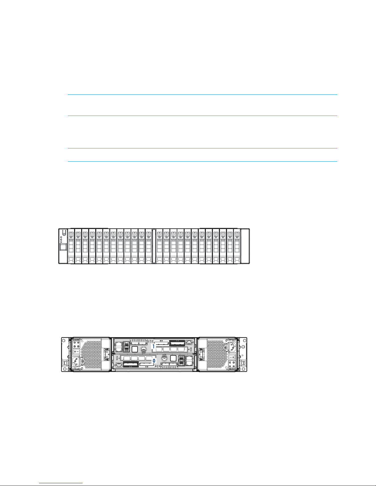
◦ The HP 3PAR StoreServ 7450 (two-node) Storage enclosures hold up to 24, 2.5 inch
small form-factor (SFF) Serial Attached SCSI (SAS) disk drives arranged vertically in a
single row. The back of the enclosure includes two 764 W power cooling modules (PCM)
and two controller nodes.
◦ The HP 3PAR StoreServ 7450 (four-node) Storage enclosure holds up to 48, 2.5 inch SFF
SAS disk drives arranged in two vertical rows. The back of the enclosure includes four
764 W PCMs and four controller nodes.
• Drive enclosures hold an array of disk drives. These are intelligent, compact, extremely dense
storage units, where each is capable of holding a large numbers of disk drives in a small rack
space (EIA-standard rack units).
◦ The HP M6710 Drive Enclosure (2U24) holds up to 24, 2.5 inch small form-factor (SFF)
SAS Solid State Disks (SSD) disk drives, installed vertically in a single row at the front of
the enclosure. The back of the enclosure contains two 580 W PCMs and two I/O modules.
◦ The HP M6720 Drive Enclosure (4U24) holds up to 24, 3.5 inch large form-factor (LFF)
SAS SSD disk drives, installed horizontally with four columns of six disk drives. The back
of the enclosure contains two 580 W PCMs and two I/O modules.
• I/O Modules connect the controller nodes to the drives using SAS cables, enabling the transfer
of data between the nodes, the drives, PCMs, and enclosures. The I/O modules are located
at the rear of the drive enclosure and are numbered 0 to 1 from bottom to top. There are two
I/O modules per enclosure.
• The HP 3PAR StoreServ 7450 Storage system can include an HP 3PAR Service Processor (SP)
or can use a Virtual Service Processor (VSP). If your configuration includes an SP, it will be
located at the bottom of the rack under the enclosures and above the power distribution units
(PDU).
HP 3PAR StoreServ 7450 Storage System Components 7
Page 8
• Power Cooling Module is an integrated power supply, battery, and cooling fan. There are
two types of PCMs:
◦ The 580 W is used in the drive enclosures and does not include a battery.
◦ The 764 W (includes a replaceable battery) is used in the node enclosures. The PCMs
are located at the rear of the system, on either side of an enclosure.
There are two PCMs per enclosure that are numbered from 0 to 1, from bottom to top and
left to right.
NOTE: In the HP M6720 Drive Enclosure, there are two PCMs that are diagonally from one
another and the remaining PCM slots are filled with blank panels.
• The Power Distribution Units (PDU) are housed in the HP G3 rack. There are two Power
Distribution Units (PDUs) that are mounted horizontally at the bottom of the rack and are
numbered 0 to 1 from bottom to top.
NOTE: Depending on the configuration, PDUs can also be mounted vertically.
The various drive enclosure and controller nodes of the HP 3PAR StoreServ 7450 Storage system
are shown.
Figure 1 Front View of HP 3PAR StoreServ 7450
Figure 2 Rear View of HP 3PAR StoreServ 7450
8 System Components and Specifications
Page 9
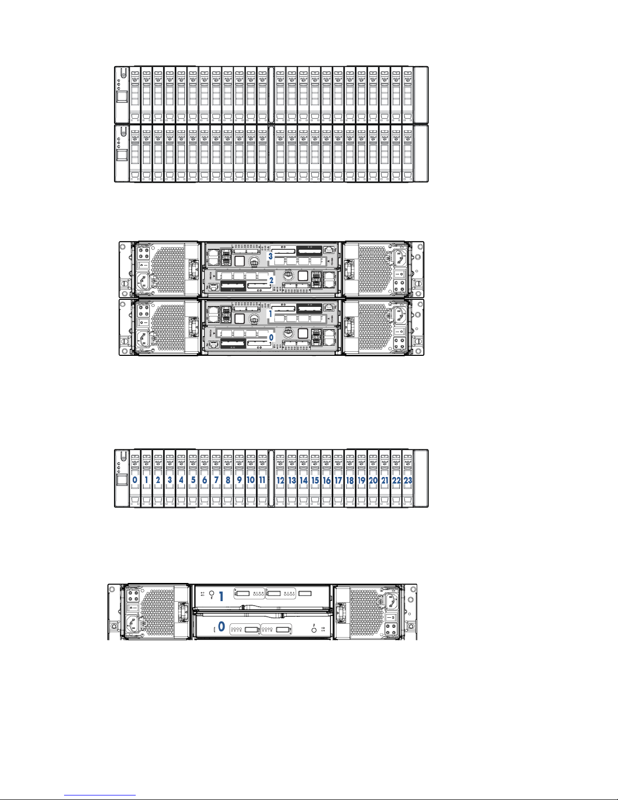
Figure 3 Front View of HP 3PAR StoreServ 7450 (Four-Node System)
Figure 4 Rear View of HP 3PAR StoreServ 7450 (Four-Node System)
Figure 5 Front View of HP M6710 Drive Enclosure (2U24)
Figure 6 Rear View of HP M6710 Drive Enclosure (2U24)
HP 3PAR StoreServ 7450 Storage System Components 9
Page 10
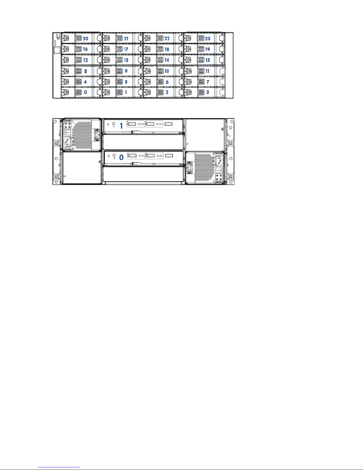
Figure 7 Front View of HP M6720 Drive Enclosure (4U24)
Figure 8 Rear View of HP M6720 Drive Enclosure (4U24)
StoreServ Storage Security Feature
HP 3PAR Data Encryption security feature allows you to encrypt all specifically formatted hard
drives on the storage system with an authentication key and the use of Self Encrypting Drives (SEDs).
Enhancing Security with Data Encryption
When a Data Encryption license is registered, you must manually enable the encryption feature
on the system. When the encryption feature is enabled successfully, all the drives in the system
become automatically set in an encrypted state. You can review the encryption status of individual
hard disk drives within the system Summary tab of the HP 3PAR Management Console.
This feature allows you to perform the following encryption-related tasks:
• Check encryption status
• Enable encryption
• Back up an authentication key
• Restore an authentication key
• Generate a new key
• Recover a key
For more information about enabling the feature, see the HP 3PAR Management Console 4.4 or
later User Guide.
Storage System Specifications
The 7450 can be configured with two nodes or four nodes. The maximum number of supported
drive enclosures varies according to the number and type of controller nodes used by the system.
Physical Specifications
The following table lists system specifications. Specifications are subject to change without notice.
10 System Components and Specifications
Page 11

Table 1 HP 3PAR StoreServ 7450 Storage Components
7450 Drive/Node Integrated Enclosure
24 Small Form-Factor (SFF) drive slotsConfiguration
2 Controller Nodes
PCIe slots (one per node) Fibre Channel HBA or iSCSI CNA
2 host FC ports
2 disk expansion SAS ports
1 1Gb Ethernet RCIP port
1 1Gb Ethernet management port
2 interconnect link ports
1 console port
3.46” (87.9mm) x 19”(483mm) x 26.6” (674.9mm)Dimensions (width x height x depth)
48.7lbs/22.1kg (no HDD); 65.5lbs/29.7kg (max)Weight
100-240 VAC 50-60HzPower
1+1 Redundant Hot Swap PCM with integrated battery
and cooling fan
112 CFMAir Flow
Front: 30” , Sides: None, Rear: 24”Service Clearances
Front: NoneCabling
Rear: Data/Power
M6710 / M6720 Drive Enclosures
2 I/O modulesConfiguration
4 SAS Ports
8 Ports
3.46” (87.9mm) x 19” (483mm) x 24.8” (630mm)M6710 Dimensions (width x height x depth)
6.89” (175mm) x 19” (483mm) x 24.9” (631.3mm)M6720 Dimensions (width x height x depth)
100-240 VAC 50-60HzPower
1+1 Redundant Hot Swap PCM with integrated cooling
fan
105 CFMM6710 Airflow
109 CFMM6720 Airflow
Front: 30” , Sides: None, Rear: 24”Service Clearances
Front: NoneCabling
Rear: Data/Power
Capacity Specifications
The following table lists system capacity and configuration details.
Storage System Specifications 11
Page 12

NOTE: SSDs have a limited number of writes that can occur before reaching the SSD's write
endurance limit. This limit is generally high enough so wear out will not occur during the expected
service life of an HP 3PAR StoreServ under the great majority of configurations, I/O patterns, and
workloads. HP 3PAR StoreServ tracks all writes to SSDs and can report the percent of the total
write endurance limit that has been used. This allows any SSD approaching the write endurance
limit to be proactively replaced before they are automatically spared out. An SSD has reached the
maximum usage limit once it exceeds its write endurance limit. Following the product warranty
period, SSDs that have exceeded the maximum usage limit will not be repaired or replaced under
HP support contracts.
Table 2 Capacity Specifications
7450 (Four Nodes)7450 (Two Nodes)Feature
42Number of controller nodes
32GB16GBControl cache
32GB16GBData cache
8–244–12Host ports
0-80-410 Gb/s iSCSI host ports
8–244–12Fibre Channel host ports
1
12–4806–240Number of drives
1
2.4TB to 864TB1.2TB to 432TBRaw capacity (approximately)
1
RAID 0, 1, 5, 6RAID 0, 1, 5, 6RAID levels
2:1 - 8:12:1 - 8:1RAID 5 data to parity ratios
Minimum physical drives to create
RAID 5 volume: 8
4:2; 6:2; 8:2; 10:2; 14:24:2; 6:2; 8:2; 10:2; 14:2RAID 6 data to parity ratios
Base RAID sets: 12 drives
Minimum physical drives to create
RAID 6 volume: 12
100 GB SSD, 200 GB SSD, 400 GB
SSD, 480 GB SSD, 920 GB SSD
100 GB SSD, 200 GB SSD, 400 GB
SSD, 480 GB SSD, 920 GB SSD
Drive capacities (in approximate GB)
1
Number of drive enclosures
2
0–180–9HP M6720 (4U24)/DC1
0–180–9HP M6710 (2U24)/DC2
1
Levels, ratios, and capacities are all mixable within the same storage system. 1 GB=1,000,000,000 bytes.
2
A single drive enclosure holds up to 24 drives in both 4U and 2U chassis within an EIA-standard rack.
12 System Components and Specifications
Page 13

Power and Heat Specifications
The following table lists the electrical power requirements.
Table 3 Power Requirements
Transactional (watts/BTU/hr)Idle (watts/BTU/hr)Component
398 W / 1357236 W / 803Node Pair, no drives, no add-on
host adapters
32.6 / 11124 W / 81.724-port 8 Gb/s Fibre Channel
Adapter
40 W / 136.434 W / 115.772-port 10 Gb/s iSCSI/FCoE
Adapter
150 / 512 (average)150 / 512 (average)HP M6710 2.5 inch 2U SAS Drive
Enclosure, no drives
164 / 559 (average)164 / 559 (average)HP M6720 3.5 inch 4U SAS Drive
Enclosure, no drives
3.9 / 13.31.4 / 4.8100 GB SLC SSD
3.9 / 13.31.4 / 4.8200 GB SLC SSD
7.5 / 12.62.2 / 3.7400 GB SLC SSD
5.5 / 18.72.2 / 7.49480 GB SLC SSD
5.2 / 17.82.0 / 6.7920 GB SLC SSD
7.1 / 24.43.2 / 11480 GB cMLC SSD
8.9 / 30.53.5/ 11.91920 GB cMLC SSD
NOTE: Refer to “Power Requirements” (page 22) for complete details.
Environmental Specifications
The operating site must comply with the following environmental specifications.
Table 4 Environmental Specifications
10,000ft/ 3,024m OperationalAltitude
40,000ft/ 12,192m Shipping
Operating: 41–104° F (5–40° C) - Reduce rating by 1° F for each 1000 ft altitude (1.8°
C/1,000 m)
Temperature
Non–operating: 32–203° F (0–95° C)
32–140° F (0–60° C)Shipping Temperature
10–90% non-condensingHumidity
10–90% non-condensingShipping Humidity
Operating: 0.25 G, Sine, 5-500 Hz; 0.15 Grms Random, 5-100 HzVibration
Non-operating: 0.5G, Sine, 5-500 Hz
Operating: 2 G, 11ms, half-sineShock
Non-operating: 10 G, 11ms, half-sine
For more information, refer to “Structural/Environmental Considerations” (page 18) for details.
Power and Heat Specifications 13
Page 14

Cable Specifications
The following table lists the types of cables commonly required for the installation of a storage
system.
Table 5 Required Cables
Connector TypeCable Type
RJ-45Ethernet (Category 5) 3 cables minimum with 3 static IPs:
• IP=SP
• IP=StorageServ
• IP For service (node rescue example)
LC-LCMulti-mode Fibre Channel Requires 50 micron OM3 cables
for 8–10Gb/s speeds.
Mini SAS SFF8088SAS cables for drive cage connections: 1M, 2M, and 6M
The following table lists the typical Fibre Channel cable lengths required for a given type of
connection.
Table 6 Fibre Channel Cable Usage Guidelines
Used For:Cable Length
Connecting Drive enclosures and controller nodes in the
same rack.
6m
Cabling between racks. Always round up to the nearest
size.
10m
25m
50m
100m
The following table lists the maximum supported Fibre Channel cable length based on the cable
size and port speed.
Table 7 Cable Limitations for Fibre Channel Host Connectivity
Cable Length LimitSpeedCable Size
300 meters4–, 8–, or 10 Gb/sOM3 and OM4
NOTE: Refer to “Network, Cabling, and Connectivity” (page 25) for more details on cable
requirements and configurations.
14 System Components and Specifications
Page 15

2 General Site Planning
Successful installation of the HP 3PAR StoreServ 7450 Storage system requires careful planning
and supervision in collaboration with authorized HP representatives. Proper planning will help
provide for a more efficient installation and greater reliability, availability, and serviceability. The
chapter includes general recommendations for physical planning and site preparation for the
storage system installation.
Customer Responsibilities
The customer must provide any hardware required to host the remote support software when
deploying a Virtual Service Processor. For scheduled service calls, the customer shall make the
Virtual Service Processor available to HP for remedial activities at the agreed-upon time. The
customer is responsible for maintaining the appropriate HP 3PAR Remote Support Technology with
a secure connection to HP and any passwords required to access the local network and Virtual
Service Processor. The customer is responsible for providing all necessary resources in accordance
with the HP 3PAR Service Processor Release Notes in order to enable the delivery of the service
and options. Please contact a local HP representative for further details on requirements,
specifications, and exclusions.
Pre-Installation Planning
When planning and preparing for the installation of a storage system, you assume the following
responsibilities:
• Providing suitable space for unpacking, installing, and operating the storage system
• Maintaining the proper environmental conditions for the storage system
• Providing adequate power facilities for the storage system
• Supplying the network connections and external cabling required by the storage system
• Enabling the appropriate HP 3PAR remote support strategy
NOTE: Electronic equipment has special packing for shipping and receives special handling
during transportation. HP is responsible for the manufacturing environment and packaging for
shipping.
For optimal performance at a specific location, storage systems require controlled environmental
conditions that can best be facilitated through raised flooring and under-floor air conditioning. It
is the customer's responsibility to monitor this environment to ensure continued conformance with
the recommended environmental specifications. Refer to “Structural/Environmental Considerations”
(page 18) for specific information concerning server room environments.
Adequate power is necessary for the reliable functioning of electronic equipment and for the safety
of the customer's installation. The customer is responsible for procuring, installing, and maintaining
adequate power to the equipment. Refer to “Power Requirements” (page 22) for input electrical
power and grounding requirements.
All pre-installation activities should be scheduled and completed before the equipment is delivered.
The pre-installation process includes the following:
• Hardware configuration planning, such as system component layout and drive allocation
• Networking and cabling topics, such as storage system and SP network topologies, internal
system cabling configurations, and cabling of connected host computers
Customer Responsibilities 15
Page 16

The following are suggested site planning tasks to be completed prior to the delivery and installation
of the selected storage system.
• Prepare a preliminary layout of the subsystem installation.
• Review the power and the heating, ventilation, and air-conditioning (HVAC) requirements.
• Order any additional support equipment indicated by the power and HVAC review.
• Work with the appropriate HP representative to ensure that all system units in the specified
configuration and all cables of the required length have been ordered.
• Make a final layout of the installation and review the layout with your HP representative.
• Select key personnel and arrange for training with your HP representative.
• Verify the electrical service wiring has been installed at the predetermined location before
installing the storage system. Refer to the respective product specifications for detailed
requirements.
• Verify any additional support equipment is properly installed and operational.
Prior to installation, review the packaging to make sure the goods have not been tampered with.
When unpacking the equipment, verify the delivered shipment of all the equipment is correct. Refer
to the packing slip and the SKUs with the shipment. Complete the installation checklist. See “Storage
System Installation Checklist” (page 36). Also, prepare the following checkpoints with your local
Sales Representative or Systems Engineer:
• Contact information for customer personnel and for HP technical sales, support, and service
personnel
• Implementation project plan
• Configuration information for the storage system to be installed, including system configuration
diagrams
• Shipping and delivery details and requirements
• Management workstation, SP, and network information
• Description of the environment
• Volume and RAID level planning information
• Additional notes and comments about installation
• Current support matrix
• System technical specifications
• Systems Acceptance Certificate
Storage System Rack Shipping Containers
A separate shipping container holds each storage system rack. The drive and node enclosure
shipping containers hold a maximum of 24 drives. Examine the delivered package for obvious
damage or signs of tampering and notify both HP and the carrier of any issues.
Shipping container measurements are as follows:
• Rack crate container: 85.35 x 50.87 x 35.43 inch (216.80 x 129.20 x 90 cm)
Approximate shipping weight: 1606 lb (728 kg)
• Drive enclosure container: Height 13 inch (33.1 cm) x Width 11 inch (28 cm) x Depth 27
inch (68.6 cm)
Approximate shipping weight: 33.8 lb (15.4 kg)
16 General Site Planning
Page 17

• Disk drive magazine container: Height 38 inch (96.5 cm) x Width 29 inch (73.6 cm) x Depth
34 inch (86.4 cm)
Approximate shipping weight: 392 lb (177.8 kg)
• Node enclosure container: Height 30 inch (76.2 cm) x Width 35 inch (88.9 cm) x Depth 45
inch (114.3 cm)
Approximate shipping weight: 618 lb (280.3 kg)
When the equipment arrives, you must make sure that there is enough room to unload and unpack
the storage system.
The specific amount of space you will need to unpack the storage system is based on the dimensions
of the container, the ramp, and the room required to access the storage system so that it can be
moved to its placement destination.
NOTE: See “Structural/Environmental Considerations” (page 18) for more information on placing
the storage systems and reserving room for service access.
Acclimatization
Storage systems are shipped or stored at extreme temperatures and may require time to adjust to
operating temperatures before startup. The maximum acceptable rate of temperature change for
a non-operating system is 36° F/hour (20° C/hour). The storage system requires time to acclimatize
to new environmental conditions before being powered on. During that time, it is possible to
proceed with the physical installation of the storage system. However, the storage system may
need at least 24 hours to acclimatize to a new environment prior to completing the full system
installation. If condensation is present even after the 24-hour acclimatization period, it is necessary
to wait until all condensation has evaporated before completing the power-on sequence.
Acclimatization 17
Page 18

3 Structural/Environmental Considerations
Consider the following when choosing or designing your facilities for the storage system:
• Equipment location and layout that allows efficient use, easy maintenance, and future
expansion.
• Facility construction that provides a suitable operating environment, sufficient power, and
adequate protection from fire, contamination, or other hazards.
• Suitable temperatures and appropriate air quality that is free from environmental contaminants.
The customer is responsible for maintaining the room environment according to the recommended
specifications. Environmental conditions for the room and under the floor must be maintained within
the acceptable limits to prevent any adverse impact on performance and reliability. The installation
environment should be monitored on a regular basis to ensure continued conformance to
recommended environmental specifications. The customer may request assistance from an HP 3PAR
representative for help with analyzing the site location and environment to make appropriate
recommendations.
For information on rack requirements and considerations, see the Best practices for HP Intelligent
Series Rack Family white paper.
Establishing the Proper Foundation
Weight and Pressure Loads
Depending on the configuration, a storage system weighs up to 2000 lb (907 kg). The following
table lists the maximum weights and pressure loads per leveling foot for storage system racks. Use
these values to approximate the structural support required by a storage system rack.
Table 8 Weight and Pressure Load Specifications
SKU
Max Ship Weight (lb)
w /Pack
Max Racked Weight
(lb) Unit + MountsDimensions (inches)Rack
QR482A89 lb65 lb37.65x23.63x11.002 Node (QR482A,
QR484A, QR483A)
QR483A71 lb51 lb35.88x23.63x11.002U Drive Enclosure
(QR490A)
QR484A160 lb129 lb36.77x23.63x14.504 Node (QR485A)
QR485A116 lb88.5 lb36.77x23.63x14.504U Drive Enclosure
(QR491A)
QR490A1.3 lb0.7 lb12.88x8.68x5.81Large Form-Factor
HDD
QR491A2.7 lb1.9 lb12.75x7.25x5.12Small Form-Factor
HDD
NOTE: The example uses nominal numbers to simplify calculations.
Anchoring Dimensions
Some installations may require the storage systems to be anchored to the floor for better stability,
especially in active seismic locations. The HP Tie Down Option Kit enables you to anchor an
Intelligent Series Rack to the floor in geographical areas that are prone to seismic activity, thereby
meeting international building code guidelines. This product provides a solution to help avoid
damage or serious injury in the event of building or floor movement.
18 Structural/Environmental Considerations
Page 19

NOTE: For information on options available for the Intelligent Series Rack, refer to the Rack
Options Catalog at www.hp.com/go/rackandpower.
For information on rack requirements and considerations, see the Best practices for HP Intelligent
Series Rack Family white paper.
Meeting Environmental Conditions
HP recommends that you maintain a controlled environment with a high degree of cleanliness,
close control of temperature and humidity, and infrequent access by personnel.
CAUTION: The storage system operating environment must be free from continuous vibration
and from dust and other environmental contaminants.
Maintaining the Optimal Temperature
The level of cooling required for the storage systems is quite different from the air-conditioning
used in offices. Air conditioning systems for comfort are designed for the lower heat and higher
moisture generated by the human body. In contrast, equipment has high heat output that is
moisture-free (sensible heat). In comfort systems, sensible heat normally produces 60–70% of the
load, whereas the dry heat of electronic equipment produces a sensible heat ratio of over 95%.
Prior to installation, verify the operating site is equipped with a cooling system that can support
all thermal emissions.
Proper site layout is critical to ensure the ambient temperature near the intake of the system does
not rise beyond the system specifications. Exceeding the maximum ambient temperature for any
period negatively affects the reliability and performance of the system. Continued operation for
extended periods under such conditions might actually cause the system to shut down.
CAUTION: Heated air from nearby equipment should not exhaust into the front of the storage
system.
Use the following average and maximum thermal emissions of storage system components to
estimate the cooling requirements for a storage system based on a specific system configuration.
Table 9 Thermal Emissions of Components
Maximum Thermal EmissionsAverage Thermal EmissionsComponent (Fully Populated)
3,004 BTU/hr (757 Kcal/hr)2,164 BTU/hr (545.3 Kcal/hr)Controller node (pair)
1
4,973 BTU/hr (1,253.2 Kcal/hr)3,657 BTU/hr (921.6 Kcal/hr)Drive enclosure (single)
9,946 BTU/hr (2,506.4 Kcal/hr)7,314 BTU/hr (1,843.2 Kcal/hr)Drive enclosure (pair)
2
1
Controller nodes can only be installed in pairs.
2
Storage systems require a minimum of two drive enclosure. However, additional drive enclosure can be installed
individually.
Storage systems can tolerate temperature and humidity fluctuations if the specified guidelines are
understood and followed. Exposure to conditions outside the specified ranges may damage the
system or its components.
Before a system is powered on, the air entering the subsystem must be clean and within the ranges
specified for temperature and humidity. The room humidity must be kept sufficiently low to prevent
condensation on or within the subsystem, and must never exceed the limit specified in the subsystem
environmental requirements tables, including transient humidity. The system must never be exposed
to conditions that could cause internal condensation to occur within the subsystem.
The air conditioning units should have controls monitoring thermal conditions underneath the floor.
Humidification is normally required to replace moisture removed during the cooling process. The
Meeting Environmental Conditions 19
Page 20

relative humidity for a subsystem equipment room should be set at 40%. This level is sufficient to
suppress electromagnetic charge buildup, and low enough to avoid the risk of corrosion and
condensation. To avoid air contamination from the humidifier, water treatment may be necessary
in areas with high mineral content.
Air Supply and Flow
The air flow capacity of the facility where the storage systems are installed needs to be sufficient
to remove the heat generated by the equipment. In addition, the air handlers must provide the
airflow volume required by the units being cooled. To ensure this airflow, the facility must have a
positive air pressure underneath the floor (if the facility has raised floors). When conditions within
the computer room are changed (new units are added, the computer system is moved, and so on),
airflow checks should be made.
The amount of outside (composition) air should be kept to the minimum needed to create a slight
positive pressure within the room, and it should not exceed industry recommendations of 0.3 cubic
meters/minute (10 cubic feet/minute) per person stationed in the equipment room. While
recommendations for outside air in comfort air conditioning are 10–15% of the airflow, the computer
room environment is cleaner and operates more efficiently if outside air is kept below 1 percent
of the airflow. Cooling/heating and humidification needs are reduced, and a minimum of
contaminated building air is introduced into the installation area.
Air Cleanliness
Air contaminants can cause equipment malfunction and can damage storage systems. It is essential
that steps be taken to prevent air contaminants, such as metal particles, solvent vapors, corrosive
gases, soot, airborne fibers, or salt, from entering or being generated within the server room
environment.
A high-efficiency air filter should be employed on each air inlet for outside air to stop dust at the
point of entry to the installation site. Special additional filtering is necessary where the environment
is exposed to salt air, corrosive gases, or unusual dust/dirt conditions. Electronic equipment is
sensitive to air contaminants such as the following:
• Excessive amounts of soot particles
• Condensate particulates such as carbonates
• Concrete particulates from unsealed concrete
• Metal flakes or filings, such as those produced by sawing, filing, or drilling
• Floor-cleaning solutions with high ammonia content.
• Deteriorating/decomposing building materials, including floor tiles, fabrics, sheetrock,
insulation, and acoustical tiles
• Pollutants generated by any servicing performed in and around the computer room
• Paper chaff, dust, and toners from printers within the computer room
• Processing chemicals from reproduction equipment such as microfiche processors.
In electronic equipment, contaminants cause connector contact and motor-bearing degradation.
They also cause electrical leakage, shorting paths between integrated circuit leads and between
printed wiring traces on printed circuit boards.
Air supplied to and circulated within the server room and plenums underneath the floor should
ideally pass through mechanical or electrostatic filters. HVAC ducts and plenums and sub-floor
areas, including cable raceway openings (where used), should be kept clean. All unused cables,
hardware, and debris should be removed from the area underneath the floor to avoid becoming
dust/dirt traps or potential sources of rust.
During major changes in the server room environment, special considerations must be taken into
account whenever any drilling, sawing, welding, brazing, and so on, is performed.
20 Structural/Environmental Considerations
Page 21

Precautions must be taken to prevent material particles (concrete or metal particles for example.)
from becoming airborne. Storage systems should be powered down during construction that
requires any drilling, sawing, welding, brazing, and so on. In addition, all debris must be removed
before powering up the systems. Maximum concentrations of corrosive gases and solvent vapors
must also be considered.
Meeting Environmental Conditions 21
Page 22

4 Power Requirements
The following describes all power domains within a HP 3PAR StoreServ 7450 Storage systems.
Electrical Requirements and Limitations
Before physically installing a storage system, verify that the operating site has the necessary electrical
circuitry. Each storage system requires four (200 - 240) Volt, 30 Amp outlets, or two outlets if only
the bottom half of the rack is occupied. For proper redundant power protection, power should be
supplied from two or more power sources. Use the approximate current requirements for storage
system components listed in “Power and Heat Specifications” (page 13) to estimate the current,
power, and heat requirements for a specific system configuration.
Power Quality
The quality of the input power is critical to the performance and reliability of the system. Variations
in the input power can cause a power failure or malfunction. Many of the causes of transient signals
and noise on commercial power lines are difficult to locate or are beyond the customer’s control.
To reduce the impact of the irregularities, some form of power conditioning may be needed. Consult
your electrician for assistance.
Voltage and Frequency Tolerance
Steady state voltage must be maintained within 10% of the normal rated voltage, measured (under
load) at the power input terminal of the specified server. The frequency must be maintained at
(50-60 HZ), 1 phase 50/60 +2%, -4%.
When there is a possibility of brownouts or other marginal voltage conditions, installing a voltage
monitor is advisable.
Systems are tested to comply with the IEC/EN 61000–4–5 standard.
HP recommends installing a lightning protection device on the server room power source when
the following conditions exist:
• The primary power is supplied by an overhead power service.
• The utility company installs lightning protectors on the primary power source.
• The area is subject to electrical storms or equivalent types of power surges.
Electrostatic Discharge
Storage systems are susceptible to failure due to Electrostatic Discharge (ESD). Electrostatic charges
can accumulate on people and furniture because of direct contact with floor coverings or movement
while in contact with furniture coverings. Discharge of static electricity to a metal surface on server
racks can interfere with the system operation and cause discomfort to anyone who comes in contact
with it.
Some factors contributing to electrostatic discharge are the following:
• High-resistance floor covering
• Carpeting without antistatic properties
• Low humidity (less than 20%)
The system is tested to comply with the IEC/EN 61000–4–2 standard.
Branch Circuits
The individual panel branch circuits should be protected by suitable circuit breakers properly rated
according to manufacturer specifications and applicable codes. Each circuit breaker should be
22 Power Requirements
Page 23

labeled to identify the branch circuit it is controlling. The receptacle should also be labeled. Plan
on a circuit breaker maximum of 30 A per PDU (de-rated to 24 A).
Emergency Power Control
As a safety precaution, you might consider providing emergency power-off controls for disconnecting
the main service wiring that supplies storage systems. Install these controls at a convenient place
for the operators and next to the main exit doors of the room after checking local electrical codes
for further guidelines.
Power Distribution Units
In HP-integrated storage systems, four PDUs are mounted horizontally below the enclosures at the
bottom rear of the rack. Numbers for PDUs are assigned beginning with 0, from bottom to top.
NOTE: If a storage system rack does not have components installed in the top portion of the rack,
do not connect and use the two upper PDUs (PDU 2 and PDU 3) to power the system. Redundant
power is still supplied to the lower bays in the rack through PDU 0 and PDU 1.
Storage system PDUs are equipped with NEMA® L6–30 or IEC 60309 connectors, depending on
the region. International PDUs are equipped with IEC 60309, 2P+E (3 wire, 2 Pole + Earth Ground)
connectors. The appropriate receptacles or adapters are necessary at the operating site to
accommodate these connectors.
Each PDU is equipped with two power banks and separate circuit breakers, used exclusively for
storage system components.
WARNING! To avoid possible injury, damage to storage system equipment, and potential loss
of data, do not use the surplus power outlets in the storage system PDUs. Never use outlets in the
PDUs to power components that do not belong to the storage system or to power storage system
components that reside in other racks.
Power Cord Connections
Storage systems arrive with all internal power cords configured. Each PDU AC cord connects to
the wall outlet and supplies power to the node and drive enclosure power supplies. The power
can be routed from the top or bottom of the rack.
Redundant Power
The storage system supports redundant power through the use of PDUs and PCMs.
WARNING! To avoid possible injury, damage to storage system equipment, and potential loss
of data, do not use the surplus power outlets in the storage system PDUs. Never use outlets in the
PDUs to power components that do not belong to the storage system or to power storage system
components that reside in other racks.
To support redundant power:
• The PCMs in each enclosure must connect to separate PDUs.
• Each PDU in the system must connect to an independent AC circuit.
Power Cooling Modules
The storage system includes an enclosure that has two PCMs, an integrated power supply, and a
cooling fan and battery, that are located at the rear of the system on either side of an enclosure.
The PCM converts current from an AC line to appropriate DC levels and supplies power to the
controller node.
Emergency Power Control 23
Page 24

There are two types of PCMs:
• 580 W PCM - Used in HP M6720 and HP M6710 drive enclosures
• 764 W PCM (includes a replaceable battery pack) - Used in controller node enclosures
The following table provides the technical specifications of the replaceable battery located inside
the 764 W PCM.
Table 10 Battery Pack Technical Specifications
DescriptionSpecifications
41° to 104° F (5° to 40° C) - Reduce rating by 1° F for
each 1000 ft altitude (1.8° C/1,000 m)
Operating Temperature
10,000 ft / 3,048 mOperating Altitude (max)
32° to 140° F (0° to 60° C)Shipping Temperature
40,000ft / 12,192 mShipping Altitude (max)
Over-Voltage, Under-Voltage, Over-Current,
Over-Temperature
Built-In Protection
49.5Wh (5.0Ah)Capacity
The battery is designed for an expected operational life of
5 years.
Design Life
2 years minimumShelf Life
Under normal operating conditions, each battery will
undergo a Maintenance Discharge Cycle once every three
Maintenance Discharge Cycles
months. System software ensures that only one battery at
a time is discharged. Maintenance Discharge Cycles test
the current charge capacity, and ensure the longest battery
life.
Minimum of 200 cycles. Expected operational life of
greater than 500 cycles
Charge/Discharge Cycles
The Battery Pack has no calendar-based Expiration or End
of Life date. End of Life is determined by reaching a
Expiration/End of Life
minimum charge capacity. This event will be reported by
the HP 3PAR software.
A battery may be replaced by removing the PCM indicating
a battery fault, removing and replacing the Battery from
the PCM, and replacing the PCM within the enclosure.
Replacement
24 Power Requirements
Page 25

5 Network, Cabling, and Connectivity
This chapter provides information about how to determine the best network configuration, including
the necessary connections and cable routing options, when installing the storage system at a
determined site.
NOTE: The following information assumes that your are working with an established network,
and explains how to connect a storage system to a network.
TCP/IP Port Assignments
The following table describes the TCP/IP port assignments for communication between various
components.
Table 11 TCP/IP Port Usage Table
Flow of TrafficUsagePort
HP 3PAR Service Processor SSH
Client --> HP 3PAR StoreServ 7450
Used by the following components for
storage system monitoring and
configuration through SSH connections:
22: The Secure Shell (SSH) Protocol
Storage
• HP 3PAR Service Processor
3rd Party SSH Client <--> HP 3PAR
• HP 3PAR OS CLI Client
Service Processor
• HP 3PAR Connection Portal
3rd Party SSH Client <--> HP 3PAR
CLI Client
WWW --> HP 3PAR Service
Processor
Used by the following component to
communicate through the HTTP protocol:
HP 3PAR Service Processor
80: World Wide Web HTTP
3rd Party SNMP Manager <--> HP
3PAR SNMP agent
Used by the following component for
storage system monitoring and
configuration by third-party SNMP
Manager applications:
161: SNMP
HP 3PAR SNMP Agent
3rd Party SNMP Manager <-- HP
3PAR SNMP agent
Used by the following component to send
unsolicited alerts as SNMPv2c traps for
3rd party SNMP Manager applications:
162: SNMPTRAP
HP 3PAR SNMP Agent
3rd Party CIM Client <--> HP 3PAR
CIM Server
Used by the following components to
provide CIM Server location information:
HP 3PAR CIM API
427: Service Location Protocol (SLP)
HP 3PAR CIM Server
Service Processor <--> HP 3PAR Event
Service
Used by the following components to
pass unsolicited events from the storage
system:
5781: 3PAR Event Reporting Service
HP 3PAR Service Processor
RM VASA event handling
HP 3PAR IMC <--> HP 3PAR CLI
Server
Used by the following components for
storage system monitoring and
5782: 3PAR Management Service
(unsecured)
HP 3PAR CLI <--> HP 3PAR CLI Serverconfiguration over an unsecured
channel:
Recovery Manager <--> HP 3PAR CLI
• HP 3PAR OS Management Console
Server
• HP 3PAR OS CLI
HP 3PAR System Reporter <--> HP
TCP/IP Port Assignments 25
Page 26

Table 11 TCP/IP Port Usage Table (continued)
Flow of TrafficUsagePort
3PAR CLI Server
HP 3PAR Service Processor --> HP
3PAR CLI Server
• HP 3PAR Recovery Manager
• HP 3PAR System Reporter
• HP 3PAR Service Processor
HP 3PAR IMC <--> HP 3PAR CLI
Used by the following components for
storage system monitoring and
configuration over a secured channel:
5783: 3PAR Management Service
with SSL (secured)
Server
HP 3PAR CLI <--> HP 3PAR CLI Server
• HP 3PAR OS Management Console
• HP 3PAR OS CLI
Recovery Manager <--> HP 3PAR CLI
Server
• HP 3PAR Recovery Manager
HP 3PAR System Reporter <--> HP
3PAR CLI Server
• HP 3PAR System Reporter
HP 3PAR Remote Copy Software on
Used by the Remote Copy Software to
receive remote replication storage data
5785: 3PAR InForm Remote Copy
the HP 3PAR StoreServ 7450sent by the Remote Copy service from
another HP 3PAR Storage Array. Storage <-- 3PAR Remote Copy on
HP 3PAR Remote Copy Software
HP 3PAR StoreServ 7450 Storage
(A dynamic port is allocated for
Unsecured port used by the Remote
Copy application to transport data (it
sending data from the Remote Copy
Software on the HP 3PAR Storage
System.)
does not exist on the management LAN
and is only visible/active on RCIP
network segments)
3rd Party CIM Client <--> HP 3PAR
CIM Server
Used by the following component for
storage system monitoring and
configuration over an unsecured
channel:
5988: WBEM CIM-XML (HTTP)
(unsecured)
HP 3PAR CIM Server
3rd Party CIM Client <--> HP 3PAR
CIM Server
Used by the following component for
storage system monitoring and
configuration over a secured channel:
5989: WBEMCIM-XML (HTTPS)
(secured)
HP 3PAR CIM Server
3rd Party WSAPI Client <-> HP 3PAR
CLI Client
Used by WSAPI client to perform HP
3PAR StoreServ 7450 administration
8008: Unsecured (HTTP) WSAPI port
3rd Party WSAPI Client <-> HP 3PAR
CLI Client
Used by WSAPI client to perform HP
3PAR StoreServ 7450 administration
8080: Secured (HTTPS) WSAPI port
Controller Node Connections
The controller nodes provide the ports that are required to connect to external drives, systems, and
other devices. A controller node contains one PCIe slot that accepts the dual-port or quad-port
Fibre Channel adapter, dual-port or quad-port NIC, or the dual port 10 Gb/s iSCSI adapter. The
number of ports available for the host connection will vary based on the configuration.
NOTE: Ethernet Port (MGMT) is also used for the management interface connection.
Fibre Channel SFP adapters are used to connect to the customer FC switch and/or hosts and can
also be used for Remote Copy operations. Depending on whether your system includes two or four
nodes and the type of PCI adapter installed (FC or CNA), a system can support a maximum of
4–24 SFPs.
26 Network, Cabling, and Connectivity
Page 27

Required Cables
The quantities and lengths of the cables required for storage system installation vary according to
the specific storage system and network configuration. Fibre Channel cables are used externally
to connect the controller node to the customer switch or host (in the case of a directly connected
host). The SAS cables are used to connect the controller node to the drive enclosures.
Table 12 Required Cables
Connector TypeOutside DiameterCable Type
Mini SAS SFF80886.60 – 7.75 mm, depending on the
length
SAS
RJ-45StandardEthernet (Category 5) 3 cables minimum
with 3 static IPs
HP recommends that you have at least
one Ethernet connection per node pair.
PCI Express6.7 mm7450 4 Node, Link Cable
LC-LC1.6 mmMultimode Fibre Channel
External Cable Connections
The following shows specific guidelines for connecting the controller nodes to the network and to
host computers. Refer to “Supported Network Topologies” (page 28) for descriptions of the supported
network topologies.
Table 13 External Controller Node Connections
Recommended ConfigurationMinimum ConfigurationConnection Type
See “Supported Network Topologies”
(page 28)
Connection from the Ethernet switch
or hub to two controller nodes
Ethernet
Separate connections from host
computers to each node, via a switch,
with connections distributed evenly
across all nodes
1
Connection from a host computer to
one controller node
Fibre Channel
Varies according to system and network
configuration
NoneMaintenance
1
To provide redundancy and to permit online software upgrades, both controller nodes in a node pair (for example,
nodes 0 and 1 and nodes 2 and 3) must maintain connections to each host server.
• Each controller node supports one Ethernet connection to a switch or hub. Separate connections
from the Ethernet switch or hub to at least two controller nodes are required to support
redundancy. With redundancy, one IP address is shared between the two connections and
only one network connection is active at a time. If the active network connection fails, the IP
address is automatically moved to the surviving network connection.
• At a minimum, the storage system requires one Fibre Channel (or iSCSI) connection from a
host computer to a controller node. However, HP recommends separate connections from
each host computer to each of the controller nodes in the storage system, with connections
distributed evenly across all nodes.
The following shows the maximum supported Fibre Channel cable length based on the cable size
and port speed:
Required Cables 27
Page 28

Table 14 Cable Limitations for Fibre Channel Host Connectivity
Cable Length LimitSpeedCable Size
100 meters2 Gb/s62.5 micron
70 meters4 Gb/s62.5 micron
21 meters8 Gb/s62.5 micron
300 meters2 Gb/s50 micron
150 meters4 Gb/s50 micron
50 meters8 Gb/s50 micron
35 meters16 Gb/s50 micron
Internal Cable Connections
NOTE: For important exceptions to the cabling rules and guidelines described in this section,
see the HP 3PAR OS Administrator’s Guide.
The following table lists the typical SAS cable lengths required for a given type of connection.
Table 15 SAS and Link Cable Usage Guidelines
Used For:Cable Length
Drive enclosure to drive enclosure and drive enclosure to
node
1m
Drive enclosure to drive enclosure and drive enclosure to
node
2m
Cabling between racks6m
7450 4-way node interconnect7450, 4-Node, Interconnect Cable:
520 mm
Cable Routing Options
For 10 Gigabit Ethernet (10GbE), iSCSI, and Fibre Channel cables that connect the storage system
to the customer network or hosts, approximately 7 feet (2 meters) of each cable must be reserved
for internal routing within the storage system rack.
Network Access
External Ethernet, iSCSI, FCoE, or Fibre Channel cable connections are completed at the time of
installation. These external connections are necessary to do the following:
• Establish connections from the controller nodes to the host computer or computers
• Connect the storage system to the network, enabling storage system management through the
HP 3PAR Management Console and HP 3PAR Command Line Interface (CLI)
• Allow communication to the storage system from the SP
Supported Network Topologies
Several different network topologies can connect the storage system to the local area network,
depending on operating site policies and requirements. Currently, the two supported topologies
are shared and private.
28 Network, Cabling, and Connectivity
Page 29

Shared
With a shared network topology, the storage system and SP share the internal customer network.
A shared topology requires all of the following:
• A static IP address and system name for the storage system
• A minimum two Ethernet connections from a switch or hub to the storage system controller
nodes, if there are more than two nodes
• A static IP address for the SP
• One Ethernet connection from a switch or hub to the SP
Private
With a private network topology, both the storage system and SP reside on the same private
network segment of the customer local area network. All management workstations used to
administer the system must also reside on the same private network segment. A private topology
requires all of the following:
• A static IP address for the storage system
• Two Ethernet connections from the storage system to a private network segment
• A minimum two Ethernet connection from the SP to the private network segment, if there are
more than two nodes
• A static IP address for the SP
• At least one management station on the private network segment
Service Processor Connectivity
The SP is used to provide remote error detection and reporting, and to support diagnostic and
maintenance activities involving the storage system.
HP uses the data collected by the SP to maintain, troubleshoot, and upgrade any HP 3PAR storage
equipment on the customer site. To perform these activities, the SP must communicate with HP
Central or a local service provider. The connection between the SP and HP Central or a local
service provider can be made by using the customer network and the Internet. Connections using
the customer network pass through a customer’s firewall. When a designated management
workstation resides on the same network as the SP and is configured to access the SP, a customer
has the option to block external communications at any time. The SP needs to be on the same
subnet as the storage system.
Table 16 Service Processor Connectivity Options
NotesSoftware Update MethodConnection Type Data Transfer /
Remote Ops
This is the preferred method of SP
connectivity.
Remote update capabilityNetwork / Network
Service Processor Connectivity 29
Page 30

6 Third-Party/Existing Rack Mounting
Some installations may use third-party or existing racks to house the HP 3PAR StoreServ 7450
Storage components. Install system components only into a standard 19-inch rack. The rack must
also be equipped with the appropriate PDUs or power receptacles and have access to an adequate
power source that provides the recommended level of redundancy.
For site administers who choose to mount storage system components, the following kits are
available:
• 7450 Node Enclosure
• Drive Enclosure
• Service Processor
NOTE: For physical dimensions and power/heat specifications for storage system components,
see “Power and Heat Specifications” (page 13). For general information on placement and
recommended conditions, see “Structural/Environmental Considerations” (page 18).
Service Installation Prerequisites
Location of Rack
• Place the rack in its final location.
• Make sure the operational power, with the correct connectors, exists in the proposed location
of the rack. The system will operate in 100-240VAC 50/60Hz and requires 200-240 VAC
PDUs or power strips. Each drive enclosure requires two C13/C14 connections. The SP
requires one C13/C14 connection.
• 36 inch (91.4 cm) of service clearance is required directly in front of the rack. This is required
due to the depth of the enclosure and potential to damage to other equipment that is in front
of the rack/enclosure.
• 30 inch (76.2 cm) of service clearance is required on both sides of the front of the rack. This
is required because two people must lift the enclosure and set into the rack. The allocated
space is necessary on each side for the person to stand and maneuver the enclosure.
• 30 inch (76.2 cm) of unobstructed clearance is required directly behind the enclosure to
service the nodes (for example, do not attach PDUs, power-strips, power cord routing, and
other things to the back of the rack). There must be unobstructed clearance directly behind
the node enclosure in order to remove or install a controller node.
Rack Requirements
• The rack is operational and has enough space for the installation. HP installation and upgrade
services does not include building a new rack, re-racking, or moving existing components.
The required contiguous rack space is defined by the quantity of 7450 Storage and drive
enclosures in the system. There must be 2U of rack space for each HP 3PAR 7450 Storage
enclosure and 2U SAS drive enclosure, 4U of rack space for the 4U SAS drive enclosure, and
1U for a service processor. HP also recommends having an open rack space above and below
the installed storage system components for drive enclosure upgrades.
• Only use a 4-post rack for an installation. Using any other types of racks is prohibited . The
vertical RETMA rails must have square holes.
30 Third-Party/Existing Rack Mounting
Page 31

• Customer cabling (power, FC, SAS, and Ethernet) must be routed in an organized path so it
does not restrict the removal of controller nodes or obstruct the servicing area.
• The rail kits for the 7000 series node and drive enclosures have a supported depth range of
24.5 inch to 32 inches (measurement between the inside of the retma rails from front to back).
Shipment of the units installed in the third party racks is NOT supported.
Enclosure Installation
• Two people are required to lift the enclosure during any servicing purposes.
Service Limitations (Also applicable to third party rack installations)
HP will not perform the following tasks:
• Assemble the rack from components
• Configure the rack hardware
• Position the rack
• Perform any extensive racking, re-racking, or cabling activities, including cabling activities
involving conduits, raceways, patch panels, and movement or configuration of computer room
floor panels.
• Complete a full site inspection, such as a comprehensive analysis of power, cooling and
humidity, airborne contaminants, vibration, and sufficient structural capability of the raised
floor in the data center to accommodate the weight of the array to be installed.
Dimensional Requirements
Refer to “Physical Specifications” (page 10) for physical specifications of the enclosures.
If you are installing any HP equipment in a four-post rack, the rack must comply with the minimum
and maximum specifications. A clear path between the front and rear vertical (RETMA) rails must
be established. There must not be any obstructions to the area when installing the rails and
enclosures.
Rack Space Considerations
HP highly recommends installing enclosures in contiguous rack space because it ensures the copper
SAS reaches the connecting ports, and provides consistency for servicing and installation. When
additional drive enclosure are added in the future, it is recommended to place them with the initial
enclosure, but it is not required.
Your site configuration should also specify an area of contiguous space within the rack for installing
HP equipment, such as the top, bottom or middle part of the rack. HP recommends considering an
area closest to the location of the sourced host cables when you are determining an installation
area.
Build the rack from bottom to top.
Maintaining Minimum Clearances
Proper clearances should be maintained for all mounted installations to allow for proper ventilation,
cabling and access for maintenance.
Table 17 Minimum Clearances
Front: 36 inch (91.4 cm)Service
Rear: 30 inch (76.2 cm) x 19 inch (50.8 cm) unobstructed clearance directly behind the enclosure.
Sides: n/a
Front: 12 inch (30.5 cm)Ventilation
Dimensional Requirements 31
Page 32

Table 17 Minimum Clearances (continued)
Rear: 12 inch (30.5 cm)
Sides: n/a
Neither vented floor tiles nor raised flooring are required.
Doors: rack doors must be at least 1.5 inch (3.81 cm) away from the front and rear of the enclosures
and be perforated with a minimum 50% open pattern across the entire surface.
Front: n/aCabling
Rear: 30 inch (76.2 cm) total clearance
Sides: n/a
Rack Mounting Kits
Table 18 Mounting Kits
Service ProcessorNode and Drive Enclosure
683811-001 Processor 1U
Mounting Kit
692982-001 for (M6720) 4U24 HDD chassis assembly
692981-001 for (M6710) 2U controller chassis assembly and 2U24 HDD chassis
assembly
Four-Post Shelf Kit
The four-post shelf kits allow the drive enclosure and components to be mounted in a variety of
four-post racks. Each enclosure or component requires its own mounting kit.
NOTE: Do not stack the enclosure on top of another one.
Four-post shelves are mounted to the front and rear rails of a four-post rack. Each side requires
two shelf halves and the corresponding mounting hardware. The shelf halves are expandable to
fit racks of different depths. Front shelf halves have left and right pieces, while the rear shelf half
can be used on either side of the rack. When the installation is complete on both the left and right
sides, the equipment can be placed on the shelves and secured to the RETMA rails.
Redundant Power Requirements
Each storage system component is supplied with redundant PCMs. The controller nodes and drive
enclosure are designed to continue operating even when AC power is lost to one of the PCMs.
For this feature to operate properly, each power supply line cord within an enclosure must be
attached to an independent electrical source, each controlled and protected by its own circuit
breaker. Multiple outlets in a power distribution unit or power strip do not constitute an independent
electrical source.
Additionally, each line cord must be plugged into an outlet that is capable of supporting the entire
load of its enclosure.
CAUTION: The PDUs are not provided with the installation kit. Verify the PDUs meet the minimum
power requirements before powering on the system. Special consideration must be given to this
requirement. Failure to do so may result in the overloading of the branch circuit if a power supply
fails, and shuts down the storage system, and cause similar failures in all the equipment connected
to the branch circuit.
CAUTION: AC line cords should be securely attached to the customer PDUs and outlets with
cord-retention mechanisms to prevent accidental disconnection during service activities. HP provides
cord retention mechanisms on HP power supplies but does not supply retention devices for
connection to the customer PDUs or outlets.
32 Third-Party/Existing Rack Mounting
Page 33

NOTE: See “Power Requirements” (page 22) for complete details about power requirements.
Redundant Power Requirements 33
Page 34

7 Support and Other Resources
Contacting HP
For worldwide technical support information, see the HP support website:
http://www.hp.com/support
Before contacting HP, collect the following information:
• Product model names and numbers
• Technical support registration number (if applicable)
• Product serial numbers
• Error messages
• Operating system type and revision level
• Detailed questions
Specify the type of support you are requesting:
Support requestHP 3PAR storage system
StoreServ 7000 StorageHP 3PAR StoreServ 7000 Storage
StoreServ 8000 StorageHP 3PAR StoreServ 8000 Storage
3PAR or 3PAR StorageHP 3PAR StoreServ 10000 Storage
StoreServ 20000 StorageHP 3PAR StoreServ 20000 Storage
HP 3PAR documentation
See:For information about:
The Single Point of Connectivity Knowledge for HP
Storage Products (SPOCK) website:
Supported hardware and software platforms
SPOCK (http://www.hp.com/storage/spock)
The HP Storage Information Library:Locating HP 3PAR documents
Storage Information Library
(http://www.hp.com/go/storage/docs/)
By default, HP 3PAR Storage is selected under Products
and Solutions.
The HP Customer Self Repair Services Media Library:Customer Self Repair procedures (media)
Customer Self Repair Services Media Library
(http://h20464.www2.hp.com/index.html)
Under Product category, select Storage. Under Product
family, select 3PAR StoreServ Storage for HP 3PAR
StoreServ 7000, 8000, 10000, and 20000 Storage
systems.
HP Support Center:All HP products
HP Support Center
(http://h20564.www2.hpe.com/portal/site/hpsc)
34 Support and Other Resources
Page 35

Typographic conventions
Table 19 Document conventions
ElementConvention
Bold text
• Keys that you press
• Text you typed into a GUI element, such as a text box
• GUI elements that you click or select, such as menu items, buttons,
and so on
Monospace text
• File and directory names
• System output
• Code
• Commands, their arguments, and argument values
<Monospace text in angle brackets>
• Code variables
• Command variables
Bold monospace text
• Commands you enter into a command line interface
• System output emphasized for scannability
WARNING! Indicates that failure to follow directions could result in bodily harm or death, or in
irreversible damage to data or to the operating system.
CAUTION: Indicates that failure to follow directions could result in damage to equipment or data.
NOTE: Provides additional information.
Required
Indicates that a procedure must be followed as directed in order to achieve a functional and
supported implementation based on testing at HP.
Documentation feedback
HP is committed to providing documentation that meets your needs. To help us improve the
documentation, send any errors, suggestions, or comments to Documentation Feedback
(docsfeedback@hp.com). Include the document title and part number, version number, or the URL
when submitting your feedback.
Typographic conventions 35
Page 36

A Storage System Installation Checklist
Use this chapter to complete all the requirements before you begin installing the storage system
hardware and software.
Storage System Hardware Installation Checklist
Before you start, verify the environmental conditions, recommended rack space access, and electrical
requirements listed in the previous chapters are satisfied and you have all of the following items:
• Standard AC power
• Host computer with access to software, BIOS, drives, and HP 3PAR OS
• Fibre Channel (FC) HBA, FC host cable, and power cord
• Other cables
• Network access
• SP connectivity
• Tools
• Rail mounting kits
• System components or storage system
Storage System Software Installation Checklist
Before you begin installing the storage system software, make sure you have all of the following
items:
• All components are installed
• The storage system setup is verified, the storage system is powered on, and the LEDs are
functioning properly
• Either the SP is installed and powered on, and you have assigned an IP addresses, or the VSP
is installed and connected, and you have determined the temporary IP address
• The SP connection is established
Table 20 SP and Storage System Software Installation Checklist
HP 3PAR Service Processor
SP ID. The SP ID is the 3PAR 7-Digit Storage serial number with the prefix SP000.
The serial number is located in two places on the SP: on the top front of the server
and in a pull-out placard in the front of the server.
NOTE: The serial number is located on the back of your HP 3PAR storage system
next to the power switch for the node enclosure PCM, and begins with 16 (for
example, 1624635).
Service Processor Host Name
Permanent IP address (IPv4 only)
Subnet mask
Gateway IP address
DNS settings:
Domain name
DNS servers
Maximum supported speed and duplex setting:
Autonegotiate or
36 Storage System Installation Checklist
Page 37

Table 20 SP and Storage System Software Installation Checklist (continued)
Custom duplex (half or full) and
Custom speed (10, 100, or 1000 MB/s)
Proxy server settings for Remote Support (if applicable):
Protocol
Address and port
Authentication information (optional)
Date and time:
Enter manually
Use NTP server information
Time zone region
New password to assign setupusr (for use with the system setup wizards)
NOTE: All passwords for the setupusr username must be between 7 and 32
characters in length and can consist of alphanumeric characters and the following
special characters: period (.), plus (+), dash (-), equal (=), and forward slash (/).
New password to assign 3parcust (to access SPOCC)
NOTE: All passwords for the 3parcust username must be between 7 and 32
characters in length and can consist of alphanumeric characters and the following
special characters: period (.), plus (+), dash (-), equal (=), and forward slash (/).
HP 3PAR Storage System
Serial number
NOTE: The serial number is located on the back of your HP 3PAR storage system
next to the power switch for the node enclosure PCM. It begins with 16 (for example,
1624635).
StoreServ system name
IP address (IPv4 only)
Subnet mask
Gateway IP address
If applicable,
• Domain Name
• DNS Server
Enable remote support:
• Protocol
• Address
• Port
Customer contact:
• Installation site information
• Customer information
Date and time:
Copy from SP
Enter manually
Use NTP server information
Time zone region
Storage System Software Installation Checklist 37
Page 38

Table 20 SP and Storage System Software Installation Checklist (continued)
New password to assign 3paradm (to access the storage system)
NOTE: Passwords for the 3paradm username can include all printable characters
and be between 6-8 characters in length.
HP 3PAR SmartStart
Performing host configurations after using SmartStart for installation setup requires
available server to run Microsoft Windows 2008 R2 x64 Edition or 2012.
38 Storage System Installation Checklist
Page 39

B File Persona Pre-Installation Checklists
Use this appendix to capture the requirements before you begin installing the file. This assumes
that the “Storage System Installation Checklist” (page 36) appendix has been used to capture the
system hardware and software requirements.
Once the system has been installed, the File Persona installation procedure involves the following
tasks:
• File Persona Hardware installation—Install network cables to connect the File Persona NICs
to the network switch infrastructure
• File Persona Node installation—Enable File Persona on 3PAR controller node pairs and define
the File Persona node networking and naming services
• File Persona Virtual File Server installation—Define Virtual File Servers and IP addresses to
present shares
• File Persona Share installation—Define and present shares
• File Persona Data Management—Backup, snapshots, and replication
File Persona Hardware Installation
Table 21 File Persona hardware installation checklist
Answer/ValueItem
For which node pairs will the File Persona be enabled?
File Persona is enabled in node pairs:
• Node 0 and node 1
• Node 2 and node 3
For File Persona, what type of network cards have been ordered for Slot 2
of each controller node?
File Persona supports two types of network cards:
• 2-port 10 GbE (Model: 560SFP+)
• 4-port 1 GbE (Model: NC365T)
How many connections will be made from each network card to the network
switch?
File Persona requires at least one network connection from each 3PAR
controller where File Persona is to be enabled.
Which bond mode will be used?
File Persona supports the following bond modes:
• 2-port 10 GbE: Mode 1 (Active/Passive)
• 4-port 1 GbE: Mode 1 (Active/Passive) or Mode 6 (Adaptive load
balancing)
All controller nodes will use the same bond mode.
Has the switch infrastructure been configured to support the File Persona
controller nodes connection?
Answer: Yes or No
Has File Persona been licensed?
Answer: Yes or No
Has the File Persona license been installed?
Answer: Yes or No
File Persona Hardware Installation 39
Page 40

File Persona Node Installation
The following checklist captures the information necessary to activate and install File Persona and
includes File Persona node networking and services such as naming, authentication, anti-virus and
backup. Each File Persona node is assigned an IP address that is used to connect to services such
as Active Directory and DNS. These IP addresses are not used for share access.
NOTE: File Persona nodes take their time from the 3PAR controllers. Ensure that the 3PAR
controllers are synchronized to an authoritative time source. If using Active Directory with File
Persona, ensure that the system and the Active Directory domain controllers synchronize their time
with the same source.
Table 22 File Persona Node Networking Checklist
Answer/ValueItem
IP address for File Persona Node 0
An IPv4 address is required for each node that will have File Persona
enabled.
IP address for File Persona Node 1
IP address for File Persona Node 2
IP address for File Persona Node 3
Network Settings: VLAN Tag for File Persona Nodes
Use of VLAN tags is optional. 0 is the default tag.
Network Settings: Subnet Mask for File Persona Nodes
The subnet mask is applicable to all File Persona nodes.
Network Settings: Gateway
File Persona supports a single default gateway which is used both for access
to network services such as DNS and during the presentation of shares to
clients.
Network Settings: MTU size
The default MTU size is 1500. Only change from the default if all
components in the network switch infrastructure support the custom frame
size.
List the DNS servers to be used by File Persona.
File Persona supports up to 3 DNS servers.
List the DNS Search Suffixes.
Authentication Settings
File Persona supports resolution of user credentials through Active Directory, LDAP or local users
and groups. Use the following table to capture the configuration information for the selected
Authentication providers.
40 File Persona Pre-Installation Checklists
Page 41

Table 23 Authentication Settings
Answer/ValueItem
Which external Authentication providers will be used?
• Active Directory:
In addition to local users and groups, File Persona supports Active Directory
and LDAP
• LDAP:
Active Directory? Answer: Yes or No
LDAP? Answer Yes or No
List the order in which Authentication providers should be used to resolve
user credentials.
• 1st:
• 2nd:
Answer example: If File Persona was used to present SMB shares to Windows
clients, the following would be the order: 1st: Active Directory, 2nd: Local
Users and Groups, and 3rd: Not Used
• 3rd:
Active Directory: Domain Name
Record the Active Directory Domain Name that the system will join for
Authentication services. All File Persona nodes will join the same Domain.
By default, an account will be created in the Computers OU for each node
using the naming format <3PAR Serial number>-<node number>.
Active Directory: User name and password
Identify an Active Directory user that has sufficient privileges to allow the File
Persona nodes to join the Active Directory Domain.
Active Directory: File Persona Share Administrator
Optional: If an account with domain administrator privileges cannot be used
to manage the File Persona share(s) permissions. Then an account must be
defined which can be used to manage File Persona share(s) permissions to
the “BUILTIN\Administrators” group with the HP 3PAR CLI command
setfsgroup –memberlist +<domain account> Administrators.
LDAP: Server Host
LDAP: Bind DN
LDAP: Base of search
LDAP: NetBios name
LDAP: Password (optional)
Password associated with the bind DN
LDAP: Schema
Answer: Posix or Samba
Posix is the default.
LDAP: Provide a Certificate (optional)
Answer: Yes or No
Use of an LDAP certificate is optional
LDAP: Certificate Protocol
Answer: TLS or SSL
Only needed if using an LDAP certificate
LDAP: Certificate common name
LDAP: Certificate file
Identify the file containing the the LDAP certificate
File Persona Node Installation 41
Page 42

Identity Mapping
File Persona supports RFC2307 for Active Directory. When RFC2307 is enabled, the Active
Directory (AD) service provides the GIDs and UIDs.
WARNING! Do not enable Identity Mapping (RFC2307) unless absolutely sure that it is required.
The default setting is disabled, the HP 3PAR StoreServ formulates the UIDs and GIDs for all AD
users and groups based on the Security Identifier (SID). When RFC2307 is enabled, you must
specify a unique UID for every user and a unique GID for every group in AD. If RFC2307 is enabled
and the user does not have a configured UID or GID in AD, the user is not given write access even
if they are granted access through an Access Control List (ACL).
Table 24 Identity Mapping
Answer/ValueItem
Enable Identity Mapping (RFC2307) for the Active Directory provider
Answer: Enable or Disable
(Disable is the Default and recommended value)
If enabled, File Persona expects UIDs and GIDs to be found in Active Directory
and not formulated using the SID as is the default behavior. This allows user
to customize UIDs and GIDs. If rfc2307is enabled when the user does not
have a configured UID/GID in Active Directory, write access is prevented,
even if granted through an ACL.
Local Groups and Users
If Local users and Groups are to be used for user authentication, complete the following tables.
Valid UID and GID are in the range 1000 to 65535.
Table 25 Local Groups and Users
Group MembersGID (Optional)Local Group Name
Table 26 Local and Primary Groups
Enable User on
Creation?Additional GroupsPrimary GroupUID (Optional)Local User Name
NOTE: The maximum number of Local User accounts supported using the local authentication
provider is 200. However, the optimal number of user accounts recommended by Hewlett-Packard
is 50 or less. In environments requiring 50 or more user accounts, Hewlett-Packard recommends
the use of a directory service {E.G. Active Directory or Lightweight Directory Access Protocol} to
manage File Persona file system permissions.
42 File Persona Pre-Installation Checklists
Page 43

Anti-Virus Settings
If the anti-virus service is to be used with File Persona shares, list the antivirus servers below.
Table 27 Anti-Virus Settings
VendorAntivirus Scan Engine PortAntivirus Scan Engine IP Address
Protocol Settings
Use the following tables to configure the NFSv4 and Object.
Table 28 NFSv4
Answer/ValueItem
NFSv4 idmap domain
NFSv4 domain name and Active Directory names are not synonymous.
Specifies NFSv4 domain name for ID mapping. For NFSv4 to work correctly,
the NFSv4 client and the NFSv4 server need to be in the same NFSv4
domain.
Table 29 Object
Answer/ValueItem
Allow persistent connections
Answer:: True or False
The default value is "true".
Connection timeout (seconds)
Specifies the timeout value in seconds for the persistent connections for the
default Object profile. The valid range is from 1 to 2592000.
The default value is 5 seconds.
Maximum simultaneous connections
Specifies the maximum number of simultaneous connections for the default
Object profile. The valid range is from 1 to 128.
The default value is 50 connections.
Read block size
Specifies the socket read block size for the default Object profile. The valid
range is from 8 K to 2048 M bytes.
The default value is 8 K.
Write block size
Specifies the file write block size for the default Object profile.
The valid range is from 8 K to 2047 M bytes.
The default value is 8 K.
File Persona Node Installation 43
Page 44

File Persona Virtual File Server Installation
A Virtual File Server (VFS) presents virtual IP addresses to allow clients to access shares. Policies
for user and group quota management and antivirus policies are managed at the VFS level. A VFS
comprises one or more IP addresses and a minimum of 1TiB of storage.
Each VFS leverages a File Provisioning Group (FPG), an instance of the HP Adaptive File System
(AFS), to control how files are stored and retrieved. The FPG has a minimum size of 1TiB and is
assigned storage from a HP 3PAR Common Provisioning Group (CPG). There is a 1:1 mapping
between a VFS and an FPG.
Replicate the following table for each VFS.
NOTE: Anti-Virus Policies, Quotas and Snapshots can be defined against a VFS post installation.
Table 30 File Persona Virtual File Server Installation
Answer/ValueItem
Name
Name of the VFS.
Comment
Optional description of the VFS
Storage Allocation: Size
The minimum size allowed for a FPG is 1 TB. Maximum FPG size is 32TB.
Each pair of nodes can manage a maximum of 64 TB.
Storage Allocation: CPG
Identify the CPG to be used to provide storage for this VFS. File Persona will
automatically create an FPG when you create the VFS and specify the CPG.
NOTE: DO NOT use the fs_cpg Common Provisioning Group (CPG) when
provisioning File Provisioning Groups (FPGs). The fs_cpg is the default CPG
for the File Persona Software Suite and should not be used.
Networking: IP Address, Subnet mask, VLAN TAG
List the IP address(es) to be assigned to the VFS. The VLAN TAG is optional
and defaults to 0.
Each VFS supports up to 4 IP addresses.
Primary Node
Answer: 1, 2, 3, or 4
Optional: File Persona will automatically assign a Primary Node for the FPG
associated with the VFS. This can be manually assigned if necessary
File Persona File Share Installation
File Shares provide data access to clients via SMB, NFS, and the Object Access API, based on
the share permissions applied to them. File Shares are presented from a File Store. File Stores are
the slice of a Virtual File Server and File Provisioning Group at which snapshots are taken, capacity
Quota Management can be performed, and Antivirus Scan Services policies customized. There
are up to 256 File Stores supported on a node pair, 16 File Stores per VFS.
The following sections detail the information to capture for each share type, SMB, NFS and Object.
44 File Persona Pre-Installation Checklists
Page 45

SMB Shares
The following table can be used to capture the configuration information for an SMB share. Replicate
the following table for each Share.
IMPORTANT: In most cases, it will be necessary to customize an SMB share’s NTFS level
permissions before putting it into production use. SMB share level permissions can be managed
using SSMC, but NTFS level permissions must be managed from an SMB client. From an SMB
client, any account with Domain Administrator privileges can manage NTFS level permissions on
a mapped share using standard Windows tools such as Windows Explorer. If you want to grant
other domain users or groups the rights to manage share permissions, add them to the File Persona
“BUILTIN\Administrators” group with the HP 3PAR CLI setfsgroup –memberlist +<domain
account> Administrators command.
Table 31 SMB Shares
Answer/ValueItem
Share Name
Name of the SMB Share.
Comment
Optional description of the Share.
Share Path: Virtual File Server
Identify the VFS used to present the share.
Share Path: File Store
Name of the File Store to use for the Share.
Share Path: Subdirectory
Additional path within the File Store to be used for this share.
Client Filter: Allow list
Optional: List the clients allowed to access the Share.
Client Filter: Deny list
Optional: List the clients denied access to the Share.
Permissions: User/Group, Type, Setting
By default, the Share will be created without any access permissions.
Type options: Allow or Deny.
Setting options: Read Only, Change, or Full Control.
Example answer: Everyone, Allow, Read Only
Settings: Access Based Enumeration
Answer: Enable or Disable
Access Based Enumeration is disabled by default.
Settings: Continuous Availability
Answer: Enable or Disable
Specifies if SMB3 continuous availability features should be enabled for this
share, enabled by default.
Settings: Offline File Support
Answer: off, manual, optimized, or auto
Specifies client-side caching for offline files. The default is manual.
File Persona File Share Installation 45
Page 46

NFS Shares
The following table can be used to capture the configuration information for an NFS share. Replicate
the following table for each NFS share.
NOTE: The following will be the export path for an NFS share:
<VFS IP>:/<FPG>/<VFS>/<File Store>/<subdirectory>
Table 32 NFS Shares
Answer/ValueItem
Share Name Name of the NFS Share.
Comment
Optional description of the Share.
Share Path: Virtual File Server
Identify the VFS used to present the share.
Share Path: File Store
Name of the File Store to use for the Share.
Share Path: Subdirectory
Additional path within the File Store to be used for this share.
Settings: Client Filter List
Specifies the clients that can access the share.
If this is not specified, the default is "*".
Share Permission
Answer: Read Only or Read Write
Share Privilege
Answer: root_squash or no_root_squash
Additional Share options
List additional share options to be defined.
46 File Persona Pre-Installation Checklists
Page 47

Object Shares
The following table can be used to capture the configuration information for an Object Share.
Replicate the table for each Object Share.
Table 33 Object Shares
Answer/ValueItem
Share Name
Name of the Object Share.
Comment
Optional description of the share.
Share Path: Virtual File Server
Identify the VFS used to present the share.
Share Path: File Store
Name of the File Store to use for the share.
Share Path: Subdirectory
Additional path within the File Store to be used for this share.
SSL
Answer: Enabled or Disabled
Path
This value is appended to http(s)://<vfs_ip>:<port>/v1/ to form
the full URL path for the Object Share.
Cross Protocol Share Access
File Persona supports scenarios where one protocol is configured to be the writing protocol and
others are configured as read-only, using Active Directory for authentication with RFC2307 user
mapping enabled.
The specific supported options within a given File Store are as follows:
• Share a folder over SMB protocol as read/write and with NFS as read-only
• Share a folder over NFS protocol as read/write and with SMB as read-only
• Share a folder for Object Access as read/write and with SMB and NFS as read-only
Describe the Cross Protocol share access requirements.
Table 34 Cross Protocol Share Access
File Persona File Share Installation 47
Page 48

File Persona Data Management
Backup
File Persona supports network share based backup over SMB or NFS protocols and NDMP over
iSCSI based backup.
Table 35 Backup
Answer/ValueItem
NDMP Target VTL devices
List the IP address of each NDMP iSCSI VTL target
NDMP DMA IP address
List the IP address of the DMA machines
NDMP DMA Username and Password
Define the username and password to be verified while connecting from the
DMA
File Store Snapshots
File based snapshots policies are assigned to File Stores. Describe the snapshot requirements for
each File Store including any scheduling of snapshots required.
Table 36 File Store Snapshots
Replication
HP 3PAR Remote Copy feature can be used with the HP 3PAR File Persona Suite to replicate the
HP 3PAR File Persona File Provisioning Groups (FPG) to another HP 3PAR running File Persona.
Consideration should be given to the Remote Copy replication link definition to ensure that there
is adequate bandwidth available to ensure that replication can cope with the anticipated file usage.
Describe the replication requirements for File Persona:
Table 37 Replication
48 File Persona Pre-Installation Checklists
Page 49

C Regulatory Compliance Notices
Regulatory Compliance Identification Numbers
For the purpose of regulatory compliance certifications and identification, this product has been
assigned a unique regulatory model number. The regulatory model number can be found on the
product nameplate label, along with all required approval markings and information. When
requesting compliance information for this product, always refer to this regulatory model number.
The regulatory model number is not the marketing name or model number of the product.
Product specific information:
HP StoreServ 7450
Regulatory model number: 3PARA-SV1009 (Controller), 3PARA- ST1111 (M6710), 3PARA-ST1112
(M6720)
FCC and CISPR classification: A
These products contain laser components. See Class 1 laser statement in the Laser compliance
notices section.
Federal Communications Commission Notice
Part 15 of the Federal Communications Commission (FCC) Rules and Regulations has established
Radio Frequency (RF) emission limits to provide an interference-free radio frequency spectrum.
Many electronic devices, including computers, generate RF energy incidental to their intended
function and are, therefore, covered by these rules. These rules place computers and related
peripheral devices into two classes, A and B, depending upon their intended installation. Class A
devices are those that may reasonably be expected to be installed in a business or commercial
environment. Class B devices are those that may reasonably be expected to be installed in a
residential environment (for example, personal computers). The FCC requires devices in both classes
to bear a label indicating the interference potential of the device as well as additional operating
instructions for the user.
Class A Equipment
This equipment has been tested and found to comply with the limits for a Class A digital device,
pursuant to Part 15 of the FCC rules. These limits are designed to provide reasonable protection
against harmful interference when the equipment is operated in a commercial environment. This
equipment generates, uses, and can radiate radio frequency energy and, if not installed and used
in accordance with the instructions, may cause harmful interference to radio communications.
Operation of this equipment in a residential area is likely to cause harmful interference, in which
case the user will be required to correct the interference at personal expense.
Declaration of Conformity for Products Marked with the FCC Logo, United States
Only
This device complies with Part 15 of the FCC Rules. Operation is subject to the following two
conditions: (1) this device may not cause harmful interference, and (2) this device must accept any
interference received, including interference that may cause undesired operation.
For questions regarding this FCC declaration, contact us by mail or telephone:
• Hewlett-Packard Company P.O. Box 692000, Mail Stop 510101 Houston, Texas 77269-2000
Or
• Call 1-281-514-3333
Modification
The FCC requires the user to be notified that any changes or modifications made to this device
that are not expressly approved by Hewlett-Packard Company may void the user's authority to
operate the equipment.
Regulatory Compliance Identification Numbers 49
Page 50

Canadian Notice (Avis Canadien)
Class A Equipment
This Class A digital apparatus meets all requirements of the Canadian Interference-Causing
Equipment Regulations.
Cet appareil numérique de la class A respecte toutes les exigences du Règlement sur le matériel
brouilleur du Canada.
European Union Notice
This compliance is indicated by the following conformity marking placed on the product:
This product complies with the following EU directives:
• Low Voltage Directive 2006/95/EC
• EMC Directive 2004/108/EC
• RoHS Directive 2011/65/EU
Compliance with these directives implies conformity to applicable harmonized European standards
(European Norms) which are listed on the EU Declaration of Conformity issued by Hewlett-Packard
for this product or product family.
Certificates can be obtained from http://www.hp.com/eu/certificates.
Hewlett-Packard GmbH, HQ-TRE, Herrenberger Strasse 140, 71034 Boeblingen, Germany
Japanese Notices
Japanese VCCI-A Notice
Japanese Power Cord Statement
50 Regulatory Compliance Notices
Page 51

Korean Notices
Class A Equipment
Taiwanese Notices
BSMI Class A Notice
Taiwan Battery Recycle Statement
Turkish Recycling Notice
Türkiye Cumhuriyeti: EEE Yönetmeliğine Uygundur
Vietnamese Information Technology and Communications Compliance
Marking
Korean Notices 51
Page 52

Laser Compliance Notices
English Laser Notice
This device may contain a laser that is classified as a Class 1 Laser Product in accordance with
U.S. FDA regulations and the IEC 60825-1. The product does not emit hazardous laser radiation.
WARNING! Use of controls or adjustments or performance of procedures other than those
specified herein or in the laser product's installation guide may result in hazardous radiation
exposure. To reduce the risk of exposure to hazardous radiation:
• Do not try to open the module enclosure. There are no user-serviceable components inside.
• Do not operate controls, make adjustments, or perform procedures to the laser device other
than those specified herein.
• Allow only HP Authorized Service technicians to repair the unit.
The Center for Devices and Radiological Health (CDRH) of the U.S. Food and Drug Administration
implemented regulations for laser products on August 2, 1976. These regulations apply to laser
products manufactured from August 1, 1976. Compliance is mandatory for products marketed in
the United States.
Dutch Laser Notice
French Laser Notice
52 Regulatory Compliance Notices
Page 53

German Laser Notice
Italian Laser Notice
Japanese Laser Notice
Laser Compliance Notices 53
Page 54

Spanish Laser Notice
Recycling Notices
English Recycling Notice
Disposal of waste equipment by users in private household in the European Union
This symbol means do not dispose of your product with your other household waste. Instead, you should
protect human health and the environment by handing over your waste equipment to a designated
collection point for the recycling of waste electrical and electronic equipment. For more information,
please contact your household waste disposal service
54 Regulatory Compliance Notices
Page 55

Bulgarian Recycling Notice
Изхвърляне на отпадъчно оборудване от потребители в частни домакинства в Европейския
съюз
Този символ върху продукта или опаковката му показва, че продуктът не трябва да се изхвърля заедно
с другите битови отпадъци. Вместо това, трябва да предпазите човешкото здраве и околната среда,
като предадете отпадъчното оборудване в предназначен за събирането му пункт за рециклиране на
неизползваемо електрическо и електронно борудване. За допълнителна информация се свържете с
фирмата по чистота, чиито услуги използвате.
Czech Recycling Notice
Likvidace zařízení v domácnostech v Evropské unii
Tento symbol znamená, že nesmíte tento produkt likvidovat spolu s jiným domovním odpadem. Místo
toho byste měli chránit lidské zdraví a životní prostředí tím, že jej předáte na k tomu určené sběrné
pracoviště, kde se zabývají recyklací elektrického a elektronického vybavení. Pro více informací kontaktujte
společnost zabývající se sběrem a svozem domovního odpadu.
Danish Recycling Notice
Bortskaffelse af brugt udstyr hos brugere i private hjem i EU
Dette symbol betyder, at produktet ikke må bortskaffes sammen med andet husholdningsaffald. Du skal
i stedet den menneskelige sundhed og miljøet ved at afl evere dit brugte udstyr på et dertil beregnet
indsamlingssted for af brugt, elektrisk og elektronisk udstyr. Kontakt nærmeste renovationsafdeling for
yderligere oplysninger.
Dutch Recycling Notice
Inzameling van afgedankte apparatuur van particuliere huishoudens in de Europese Unie
Dit symbool betekent dat het product niet mag worden gedeponeerd bij het overige huishoudelijke afval.
Bescherm de gezondheid en het milieu door afgedankte apparatuur in te leveren bij een hiervoor bestemd
inzamelpunt voor recycling van afgedankte elektrische en elektronische apparatuur. Neem voor meer
informatie contact op met uw gemeentereinigingsdienst.
Recycling Notices 55
Page 56

Estonian Recycling Notice
Äravisatavate seadmete likvideerimine Euroopa Liidu eramajapidamistes
See märk näitab, et seadet ei tohi visata olmeprügi hulka. Inimeste tervise ja keskkonna säästmise nimel
tuleb äravisatav toode tuua elektriliste ja elektrooniliste seadmete käitlemisega egelevasse kogumispunkti.
Küsimuste korral pöörduge kohaliku prügikäitlusettevõtte poole.
Finnish Recycling Notice
Kotitalousjätteiden hävittäminen Euroopan unionin alueella
Tämä symboli merkitsee, että laitetta ei saa hävittää muiden kotitalousjätteiden mukana. Sen sijaan sinun
on suojattava ihmisten terveyttä ja ympäristöä toimittamalla käytöstä poistettu laite sähkö- tai
elektroniikkajätteen kierrätyspisteeseen. Lisätietoja saat jätehuoltoyhtiöltä.
French Recycling Notice
Mise au rebut d'équipement par les utilisateurs privés dans l'Union Européenne
Ce symbole indique que vous ne devez pas jeter votre produit avec les ordures ménagères. Il est de
votre responsabilité de protéger la santé et l'environnement et de vous débarrasser de votre équipement
en le remettant à une déchetterie effectuant le recyclage des équipements électriques et électroniques.
Pour de plus amples informations, prenez contact avec votre service d'élimination des ordures ménagères.
German Recycling Notice
Entsorgung von Altgeräten von Benutzern in privaten Haushalten in der EU
Dieses Symbol besagt, dass dieses Produkt nicht mit dem Haushaltsmüll entsorgt werden darf. Zum
Schutze der Gesundheit und der Umwelt sollten Sie stattdessen Ihre Altgeräte zur Entsorgung einer dafür
vorgesehenen Recyclingstelle für elektrische und elektronische Geräte übergeben. Weitere Informationen
erhalten Sie von Ihrem Entsorgungsunternehmen für Hausmüll.
56 Regulatory Compliance Notices
Page 57

Greek Recycling Notice
Απόρριψη άχρηοτου εξοπλισμού από ιδιώτες χρήστες στην Ευρωπαϊκή Ένωση
Αυτό το σύμβολο σημαίνει ότι δεν πρέπει να απορρίψετε το προϊόν με τα λοιπά οικιακά απορρίμματα.
Αντίθετα, πρέπει να προστατέψετε την ανθρώπινη υγεία και το περιβάλλον παραδίδοντας τον άχρηστο
εξοπλισμό σας σε εξουσιοδοτημένο σημείο συλλογής για την ανακύκλωση άχρηστου ηλεκτρικού και
ηλεκτρονικού εξοπλισμού. Για περισσότερες πληροφορίες, επικοινωνήστε με την υπηρεσία απόρριψης
απορριμμάτων της περιοχής σας.
Hungarian Recycling Notice
A hulladék anyagok megsemmisítése az Európai Unió háztartásaiban
Ez a szimbólum azt jelzi, hogy a készüléket nem szabad a háztartási hulladékkal együtt kidobni. Ehelyett
a leselejtezett berendezéseknek az elektromos vagy elektronikus hulladék átvételére kijelölt helyen történő
beszolgáltatásával megóvja az emberi egészséget és a környezetet.További információt a helyi
köztisztasági vállalattól kaphat.
Italian Recycling Notice
Smaltimento di apparecchiature usate da parte di utenti privati nell'Unione Europea
Questo simbolo avvisa di non smaltire il prodotto con i normali rifi uti domestici. Rispettare la salute
umana e l'ambiente conferendo l'apparecchiatura dismessa a un centro di raccolta designato per il
riciclo di apparecchiature elettroniche ed elettriche. Per ulteriori informazioni, rivolgersi al servizio per
lo smaltimento dei rifi uti domestici.
Latvian Recycling Notice
Europos Sąjungos namų ūkio vartotojų įrangos atliekų šalinimas
Šis simbolis nurodo, kad gaminio negalima išmesti kartu su kitomis buitinėmis atliekomis. Kad
apsaugotumėte žmonių sveikatą ir aplinką, pasenusią nenaudojamą įrangą turite nuvežti į elektrinių ir
elektroninių atliekų surinkimo punktą. Daugiau informacijos teiraukitės buitinių atliekų surinkimo tarnybos.
Recycling Notices 57
Page 58

Lithuanian Recycling Notice
Nolietotu iekārtu iznīcināšanas noteikumi lietotājiem Eiropas Savienības privātajās mājsaimniecībās
Šis simbols norāda, ka ierīci nedrīkst utilizēt kopā ar citiem mājsaimniecības atkritumiem. Jums jārūpējas
par cilvēku veselības un vides aizsardzību, nododot lietoto aprīkojumu otrreizējai pārstrādei īpašā lietotu
elektrisko un elektronisko ierīču savākšanas punktā. Lai iegūtu plašāku informāciju, lūdzu, sazinieties ar
savu mājsaimniecības atkritumu likvidēšanas dienestu.
Polish Recycling Notice
Utylizacja zużytego sprzętu przez użytkowników w prywatnych gospodarstwach domowych w
krajach Unii Europejskiej
Ten symbol oznacza, że nie wolno wyrzucać produktu wraz z innymi domowymi odpadkami.
Obowiązkiem użytkownika jest ochrona zdrowa ludzkiego i środowiska przez przekazanie zużytego
sprzętu do wyznaczonego punktu zajmującego się recyklingiem odpadów powstałych ze sprzętu
elektrycznego i elektronicznego. Więcej informacji można uzyskać od lokalnej firmy zajmującej wywozem
nieczystości.
Portuguese Recycling Notice
Descarte de equipamentos usados por utilizadores domésticos na União Europeia
Este símbolo indica que não deve descartar o seu produto juntamente com os outros lixos domiciliares.
Ao invés disso, deve proteger a saúde humana e o meio ambiente levando o seu equipamento para
descarte em um ponto de recolha destinado à reciclagem de resíduos de equipamentos eléctricos e
electrónicos. Para obter mais informações, contacte o seu serviço de tratamento de resíduos domésticos.
Romanian Recycling Notice
Casarea echipamentului uzat de către utilizatorii casnici din Uniunea Europeană
Acest simbol înseamnă să nu se arunce produsul cu alte deşeuri menajere. În schimb, trebuie să protejaţi
sănătatea umană şi mediul predând echipamentul uzat la un punct de colectare desemnat pentru reciclarea
echipamentelor electrice şi electronice uzate. Pentru informaţii suplimentare, vă rugăm să contactaţi
serviciul de eliminare a deşeurilor menajere local.
58 Regulatory Compliance Notices
Page 59

Slovak Recycling Notice
Likvidácia vyradených zariadení používateľmi v domácnostiach v Európskej únii
Tento symbol znamená, že tento produkt sa nemá likvidovať s ostatným domovým odpadom. Namiesto
toho by ste mali chrániť ľudské zdravie a životné prostredie odovzdaním odpadového zariadenia na
zbernom mieste, ktoré je určené na recykláciu odpadových elektrických a elektronických zariadení.
Ďalšie informácie získate od spoločnosti zaoberajúcej sa likvidáciou domového odpadu.
Spanish Recycling Notice
Eliminación de los equipos que ya no se utilizan en entornos domésticos de la Unión Europea
Este símbolo indica que este producto no debe eliminarse con los residuos domésticos. En lugar de ello,
debe evitar causar daños a la salud de las personas y al medio ambiente llevando los equipos que no
utilice a un punto de recogida designado para el reciclaje de equipos eléctricos y electrónicos que ya
no se utilizan. Para obtener más información, póngase en contacto con el servicio de recogida de
residuos domésticos.
Swedish Recycling Notice
Hantering av elektroniskt avfall för hemanvändare inom EU
Den här symbolen innebär att du inte ska kasta din produkt i hushållsavfallet. Värna i stället om natur
och miljö genom att lämna in uttjänt utrustning på anvisad insamlingsplats. Allt elektriskt och elektroniskt
avfall går sedan vidare till återvinning. Kontakta ditt återvinningsföretag för mer information.
Battery Replacement Notices
Dutch Battery Notice
Battery Replacement Notices 59
Page 60

French Battery Notice
German Battery Notice
60 Regulatory Compliance Notices
Page 61

Italian Battery Notice
Japanese Battery Notice
Battery Replacement Notices 61
Page 62

Spanish Battery Notice
62 Regulatory Compliance Notices
 Loading...