

Page 1
HP 2920-24G, 2920-48G, 2920-24G PoE+, and 2920-48G PoE+ Switches
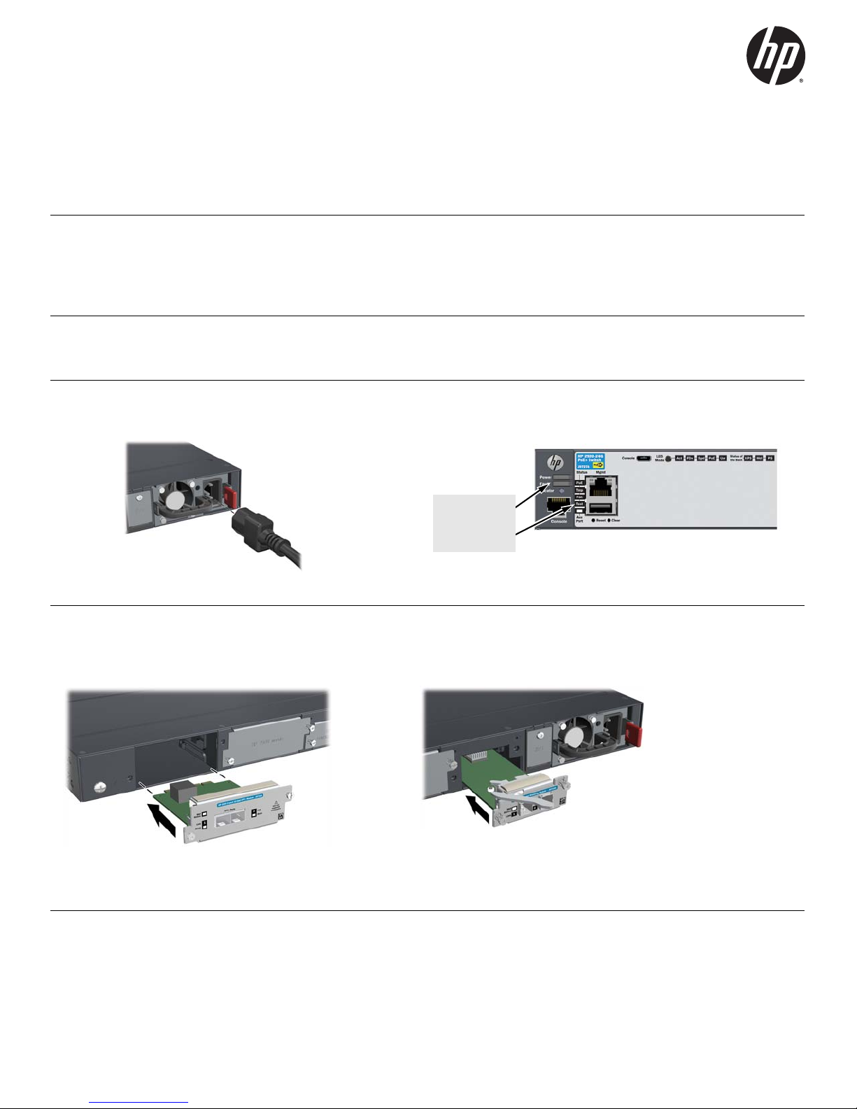
After Self-Test:
Power LED = On
Fault LED = Off
Test LED = Off
Quick Setup Guide
For more detailed instructions and information to set up your switch, view or download the Installation and Getting Started
Guide for your switch at www.hp.com/networking/support.
1. Unpack and check included parts. ■ Documentation kit
■ Switch
■ Console port serial cable (DB-9 to RJ-45)
■ Accessory kit (installation hardware)
■ AC power cord
2. Prepare for installation. To avoid personal injury or product damage, review the “Safety Precautions” on
page 4.
3. Power on the switch and verify that Self-Test completes normally. The switch does not contain a power switch. It
is powered on by connecting power through the AC power cord. After verification, unplug the switch.
4. (Optional) Install Modules. On the back of the switch are slots for 10 Gbps network connectivity and for high-speed
stacking. See the switch Installation and Getting Started Guide for more information on the use of these modules and
supported stacking topologies.
HP 2920 10GbE Module HP 2920 Stacking Module
1
Page 2
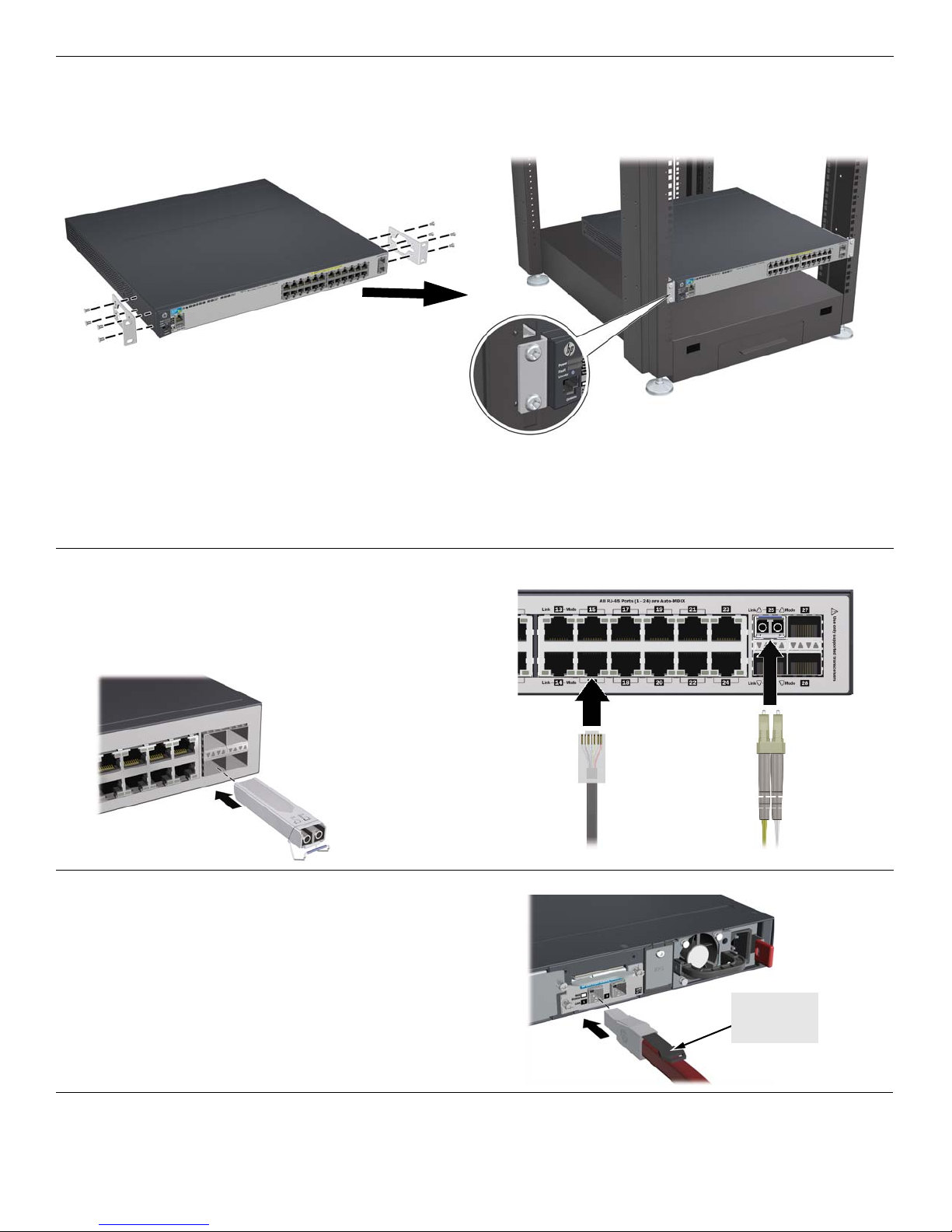
5. Install the Switch Hardware. Unplug the AC power from the switch before installing the switch hardware.
Make sure that
the pull tab is on
the top
■ Rack Mounting: Use a #1 Phillips (cross-head) screwdriver to attach the accessory kit brackets to the switch using
the eight 8-mm M4 screws. Then use the four number 12-24 screws to secure the brackets to the rack.
Note: A rail kit is available for mounting the switch in 4-post racks. For more information, see the Installation and
Getting Started Guide for your switch.
■ Table or Desktop Mounting: Attach the four self-adhesive pads (included in the accessory kit) to the bottom
corners of the switch.
6. Connect Network Cables.
Note: For transceiver connections, install and use only HP
SFP transceivers supported by the switch.
See “SFP Installation Notes” on page 3.
7. Connect stacking cables. If you are stacking multiple HP 2920
switches together, then connect them into a supported stacking
topology using HP 2920 Stacking Modules and stacking cables. For
more information on supported stacking topologies, see the
Installation and Getting Started Guide for your switch.
Caution: Make sure to connect the stacking cable with the
pull tab on the top. Insert the cable until it clicks into place.
To disconnect the cable, pull on the pull tab.
8. Power On the Switch. As shown in step 3.
2
Page 3
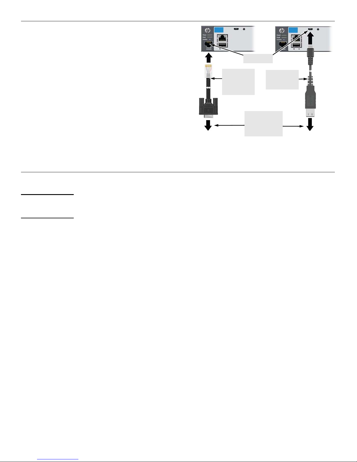
9. (Optional) Configure the Switch for Management.
RJ-45 to DB9
Console cable
supplied with
the switch
To PC running a
terminal emulator
program, or a
VT-100 terminal
Console port
Optional USB
Console cable
(not supplied) *
By factory default, the switch will automatically obtain its IP
network configuration from a DHCP or BootP server. Subsequently,
you can determine the IP address assigned to the switch by
inspecting your DHCP/BootP server, or by using LLDP from a
connected device.
You can also manage and configure the switch through a console
port connection. Connect a VT-100 terminal or PC (with suitable
terminal emulation software) to the switch using the serial cable
(DB-9 and RJ-45 connectors) supplied with the switch.
* Note: You can also connect a console to the switch via the USB
console port (cable not provided). For more information on using
the USB console port, see the switch Installation and Getting
Started Guide for your switch.
For information on configuration and remote management, see the
Management and Configuration Guide for your switch. The
manuals are available at www.hp.com/networking/support.
SFP Installation Notes
Note Use only genuine HP SFP transceivers supported by your switch.
When selecting a fiber SFP device, make sure it can function at a temperature that is not less than the recommended
maximum operational temperature of the switch. Use only an approved Laser Class 1 SFP transceivers.
Use only genuine HP SFPs. Non-HP SFP transceivers are not supported. Use of genuine HP products ensures that your network
maintains optimal performance and reliability. Should you require additional transceivers, please contact an HP sales representative or an
authorized reseller.
Hot Swapping SFP transceivers. Supported SFP transceivers that you can install in your HP switch can be “hot swapped” – removed
and installed while the switch is receiving power. You should disconnect the network cables from the SFP transceivers before hot-swapping
them, though.
When you replace an SFP transceiver with another of a different type, the switch may retain selected port-specific configuration settings
that were configured for the replaced unit. Be sure to validate or reconfigure port settings as required.
SFP Connections to Devices with Fixed Speed/Duplex Configurations. When connecting a device to your switch port that contains
an SFP transceiver, the speed and duplex settings of the switch port and the connected device must match. Otherwise, the device may not
link properly — you may not get a link. For some older network devices, including some older HP devices, the default speed/duplex settings
may be predefined (for example, to 1000 Mbps/Full Duplex), or otherwise set differently from the default configuration of your switch port.
Because of these default speed/duplex considerations, you should make sure that devices connected to your SFP ports are properly
configured. At a minimum, make sure the configurations match.
3
Page 4

Safety Precautions
Printed in China
December 2012
5998-3573
*5998-3573*
© Copyright 2012 Hewlett-Packard Company, L.P.
The information contained herein is subject to change
without notice.
To avoid personal injury or product damage when installing your switch, read the installation precautions and guidelines below.
Installation Precautions
Warnings
■ The rack or cabinet should be adequately secured to prevent it from becoming unstable, tilting or falling.
■ Devices installed in a rack or cabinet should be mounted as low as possible, with the heaviest devices at
the bottom and progressively lighter devices above.
Cautions
■ Ensure the power source circuits are properly grounded, then use the power cord supplied with the switch to connect
to the AC power source.
■ If your installation requires a different power cord than the one supplied with the switch and/or power supply, be
sure the cord is adequately sized for the switch’s current requirements. In addition, be sure to use a power cord
displaying the mark of the safety agency that defines the regulations for power cords in your country/region. The
mark is your assurance that the power cord can be used safely with the switch and power supply.
■ When installing the switch, the AC outlet should be near the switch and should be easily accessible in case the switch
must be powered off.
■ Ensure the switch does not overload the power circuits, wiring, and over-current protection. To determine the
possibility of overloading the supply circuits, add together the ampere ratings of all devices installed on the same
circuit as the switch and compare the total with the rating limit for the circuit. The maximum ampere ratings are
usually printed on the devices near the AC power connectors.
■ Do not install the switch in an environment where the operating ambient temperature exceeds its specification.
■ Ensure the air flow around the switch is not restricted. Leave at least 7.6 cm (3 inches) for cooling. For the air flow
direction, see the Installation and Getting Started Guide for your product, located on the HP Networking web site
at www.hp.com/networking/support.
For additional Safety and Regulatory information, refer to the Safety and Regulatory documentation included with your switch.
 Loading...