

Page 1
HP 2566C/HP 2567C
Operator's Manual
HEWLETT
"HM PACKARD
Page 2

HP2566C/HP2567C
OPERATORS MANUAL
HEWLETT
PACKARD
HP Part No. 02566-90990
Printed in USA April 1990
1st edition
Page 3

NOTICE
HEWLETT-PACKARD MAKES NO WARRANTY OF ANY
KIND WITH REGARD TO THIS MATERIAL, INCLUDING,
BUT NOT LIMITED TO, THE IMPLIED WARRANTIES OF
MERCHANTABILITY AND FITNESS FOR A PARTICULAR
PURPOSE. Hewlett-Packard shall not be liable for errors contained
herein or for incidental or consequential damages in connection with the
furnishing, performance or use of this material.
Hewlett-Packard assumes no responsibility for the use or reliability of its
software on equipment that is not furnished by Hewlett-Packard.
This document contains proprietary information which is protected
by copyright. All rights are reserved. No part of this document
may be photocopied or reproduced without prior written consent of
Hewlett-Packard Company.
PUBLICATION
HISTORY
Changes in text to document updates subsequent to the initial release
are supplied in new editions of the manual. The printing histoiy
(edition) of the manual is shown on the title page. The last edition date
itemized reflects the machine configuration documented in the manual.
FOR U.Sj\. ONLY
The Federal Communications (in 47 CFR 15.818) has specified that the
following notice be brought to the attention of the user of the product.
FEDERAL COMMUNICATIONS COMMISSION RADIO
FREQUENCY INTERFERENCE STATEMENT
Warning: This equipment generates, uses, and can radiate radio
frequency energy and if not installed and used in accordance with the
instructions manual, may cause interference to radion communications.
It has been tested and found to comply with the limits for Class A
computing devices pursuant to Subpart J of Part 15 of FCC Rules, which
are designed to provide reasonable protection against such interference
when operated in a commercial environment. Operation of this
equipment in a residential area is likely to cause interference in which
case the user at his own expense will be required to take whatever
measures may be required to correct the interference.
©Hewlett-Packard Company 1990
Page 4

Contents
Inside This Manual
1. GENERAL INFORMATION
Introduction............................................................................................................................... 1-1
Product Description................................................................................................................. 1-2
Supplies and Accessories ........................................................................................................ 1-5
Service..................................................................................................................................... 1-6
Operator Safety ....................................................................................................................... 1-6
2. GETTING THE MOST FROM YOUR PRINTER AND PAPER
Printer Location......................................................................................................................... 2-1
Printer Installation..................................................................................................................... 2-1
Power......................................................................................................................................... 2-4
Paper Requirements................................................................................................................... 2-4
Paper Storage and Handling...................................................................................................... 2-5
3. PREPARING THE PRINTER FOR OPERATION
Ribbon Removal and Replacement........................................................................................... 3-1
Paper Loading and Adjustment ............................................................................................. 3-10
Adjusting Vertical Paper Tension.......................................................................................... 3-15
Adjusting Forms Position...................................................................................................... 3-17
Adjusting Forms Thickness................................................................................................... 3-21
Overall Print Quality.............................................................................................................. 3-24
Adjusting Forms Length ....................................................................................................... 3-25
Adjusting Top of Form.......................................................................................................... 3-30
4. USING THE POWERED PAPER STACKER
Unloading the Paper Stack ....................................................................................................... 4-7
5. PRINTER CONFIGURATION
Setting Configuration Functions
Interface Configuration............................................................................................................. 5-5
HP-IB Selection......................................................................................................................... 5-6
Test............................................................................................................................................ 5-7
...............................................................................................
Contents-1
5-1
Page 5

6. USING THE PRINTER
Printer Modes............................................................................................................................ 6-1
Printer Status Mode................................................................................................................... 6-2
Operator Controls and Indicators............................................................................................. 6-3
Power-On Parameters and Power-Fail Recovery
..................................................................
Graphics Printing .................................................................................................................. 6-12
Vertical Forms Control.......................................................................................................... 6-13
Optimizing Print Quality....................................................................................................... 6-14
Preventive Maintenance......................................................................................................... 6-16
7. IN CASE OF DIFFICULTY
General Problems .................................................................................................................... 7-2
Printer Errors............................................................................................................................ 7-4
Calling for Help..................................................................................................................... 7-8
A. PRINTER SPECIFICATIONS
Certification.............................................................................................................................. A-1
Printer Overview....................................................................................................................... A-1
Physical Specifications .......................................................................................................... A-3
Electrical Characteristics ........................................................................................................ A-3
Performance Specifications .................................................................................................... A-5
Environmental Specifications ................................................................................................ A-7
6-11
B. PAPER SPECIFICATIONS
Certification.............................................................................................................................. B-1
Standard Forms Specifications................................................................................................. B-1
Speciality Forms Specifications................................................................................................ B-3
C. RIBBON SPECIFICATIONS
Index
Self-Test Printout
User Comment Sheet
Hewlett-Packard Sales and Service Offices
Contents-2
Page 6

Figures
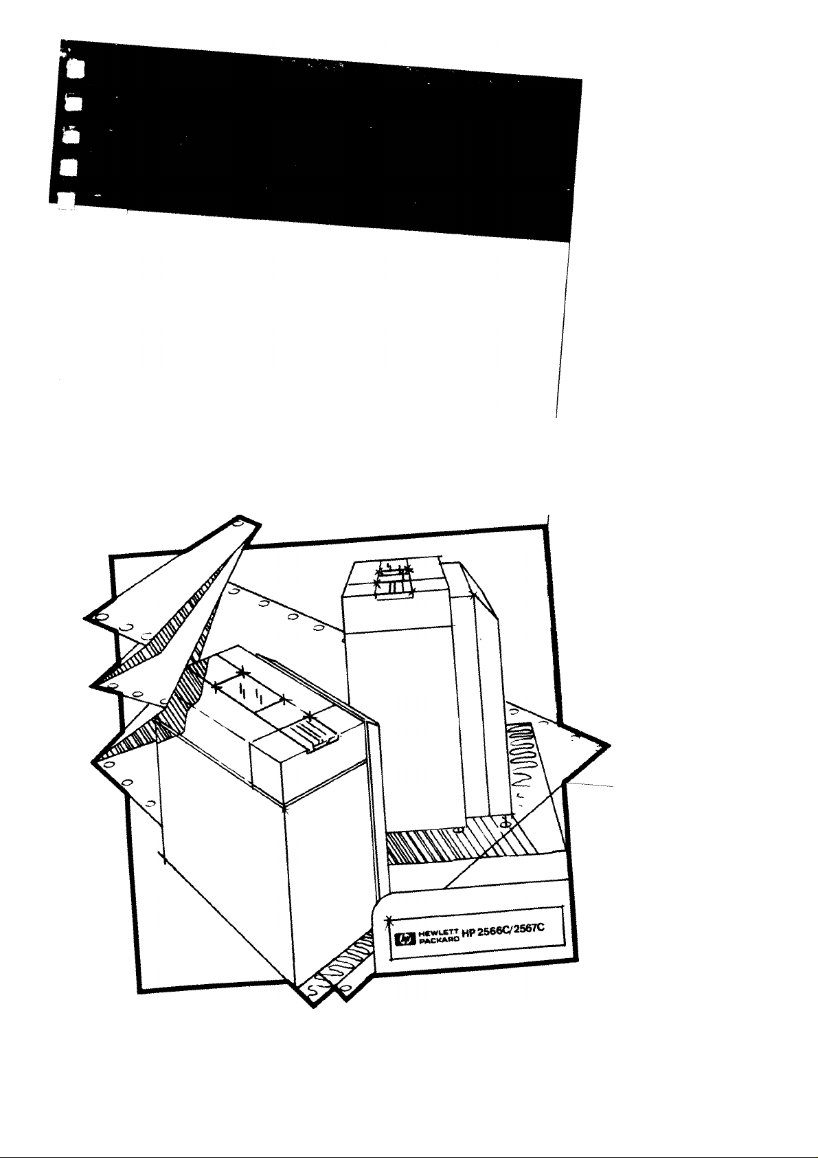
1- 1. HP2566C/HP2567C Printer with powered paper stacker
2- 1. Shipping Lock Bracket Locations..................................................................................... 2-2
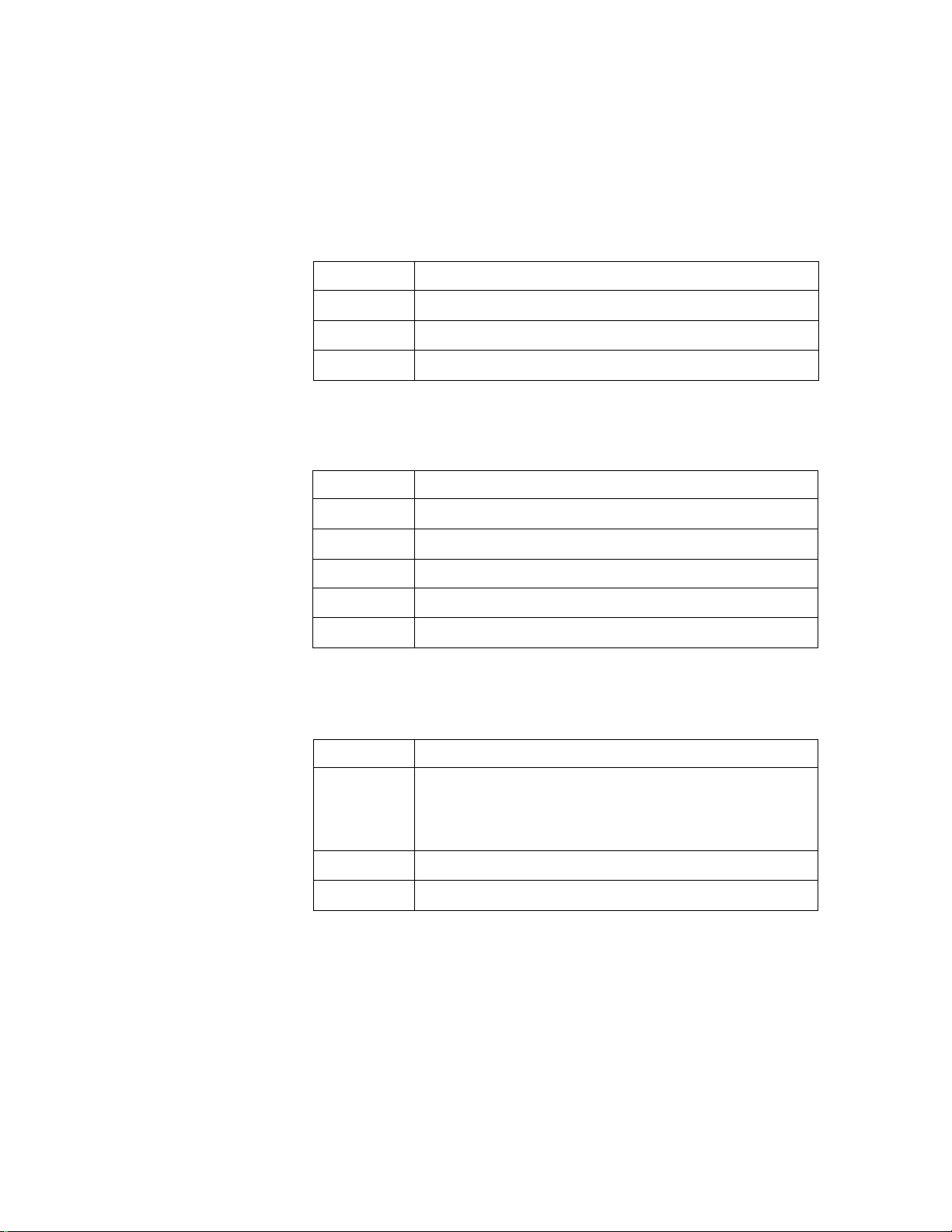
3- 1. Opening the Ribbon Cover................................................................................................ 3-2
3-2. Removing Upper Ribbon Spool............................................................................................ 3-3
3-3. Opening the Swing-Gate ...................................................................................................... 3-3
3-4. Accessing Lower Ribbon Spool........................................................................................... 3-4
3-5. Removing Lower Ribbon Spool........................................................................................... 3-4
3-6. Removing the Ribbon........................................................................................................... 3-5
3-7. Correct Ribbon Winding Direction
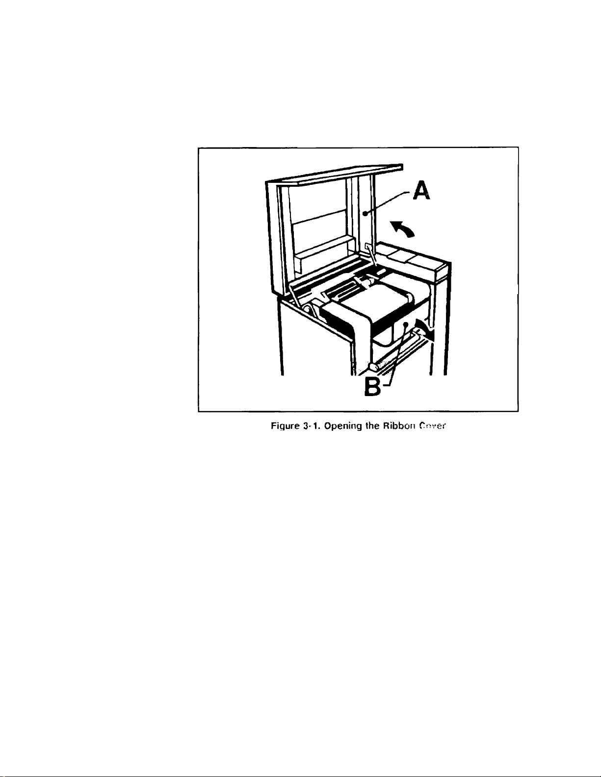
3-8. Lowering Ribbon Shield and Opening Ribbon Access Cover
3- 9. Installing Lower Ribbon Spool......................................................................................... 3-7
3-10. Closing Lower Ribbon Cover and Paper Shield................................................................... 3-8
3-11. Installing Upper Ribbon Spool............................................................................................. 3-9
3-12. Closing the Printer................................................................................................................ 3-9
3-13. Opening the Printer ............................................................................................................ 3-10
3-14. Opening the Swing-Gate ................................................................................................... 3-11
3-15. Opening the Platen.............................................................................................................. 3-12
3-16. Opening the Tractors.......................................................................................................... 3-13
3-17. Positioning the Paper.......................................................................................................... 3-14
3-18. Adjusting Vertical Paper Tension....................................................................................... 3-15
3-19. Tractor Controls.................................................................................................................. 3-17
3-20. Adjusting Forms Position................................................................................................... 3-18
3-21. Tractor Strip Distortion....................................................................................................... 3-20
3-22. Setting the Forms Thickness Lever at Maximum Thickness
3-23. Dot Slalom.......................................................................................................................... 3-22
3-24. Character Scrunch............................................................................................................... 3-24
3-25. Parts of the Form ............................................................................................................... 3-25
3-26. Adjusting Paper Over the Platen......................................................................................... 3-30
3-27. Lowering the Paper Shield................................................................................................. 3-31
3-28. Positioning Paper to the First Column of Print
3-29. Top of Form Alignment Guide Labels............................................................................... 3-33
3-30. Top of Form Index Label.................................................................................................... 3-34
3-31. Positioning Alignment Guide Labels
3-32. Recording Information on Index Label
4- 1. Sliding Out the Paper Tray................................................................................................ 4-1
4-2. Positioning the Backstop ..................................................................................................... 4-2
4-3. Pushing In the Paper Tray .................................................................................................... 4-3
4-4. Adjusting Door Chains......................................................................................................... 4-4
4-5. Starting the Paper Stack ....................................................................................................... 4-5
4- 6. Aligning the Paper Stack................................................................................................... 4-6
5- 1. Character Set Self-Test Example
6- 1. Display Modes.................................................................................................................. 6-1
......................................................................................
.................................................................
.................................................................................
.............................................................................
......................................................................................
.................................................
.............................................
.............................................
1-1
3-5
3-6
3-21
3-31
3-35
3-36
5-3
Contents-3
Page 7

6-2. Parts of the Printer................................................................................................................ 6-3
6-3. Operator Control Panel......................................................................................................... 6-4
6-4. Forms Loading Controls....................................................................................................... 6-9
6-5. Forms Thickness Adjustment Lever .................................................................................. 6-10
6- 6. Dot Slalom....................................................................................................................... 6-15
7- 1. Character Scrunch.............................................................................................................. 7-4
A-1. Dot-Matrix and Full-Font Print Gap Comparison
B-1. Maximum Height of Form Defects...................................................................................... B-3
B-2. Maximum Thickness Variation for All Areas of a Special Form
B-3. Maximum Thickness Variation for the Thin Areas of a Special Form................................. B-4
B-4. Maximum Allowable Form Perforation Projection......................................................... B-5
.........................................................
........................................
Tables
1-1. Character Sets....................................................................................................................... 1-5
1-2. Power Supplies..................................................................................................................... 1-6
1-3. Interface Subsystems............................................................................................................ 1-6
1-4. Convenience Options............................................................................................................ 1-6
1-5. Recommended Printer Paper................................................................................................ 1-7
4-1. Recommended Backstop Positions....................................................................................... 4-2
4- 2. Recommended Door Chain Positions................................................................................ 4-4
5- 1. Configuration Function Numbers ..................................................................................... 5-2
5- 2. Sub-Test Numbers............................................................................................................. 5-8
6- 1. Status Codes...................................................................................................................... 6-2
6- 2. VFC Channel Definitions................................................................................................ 6-13
7- 1. Run-time Errors................................................................................................................. 7-6
7-2. Self-Test Error Numbers...................................................................................................... 7-7
A-1. Print Speed and Matrix Sizes - HP2566C...................................................................... A-5
A-2. Print Speed and Matrix Sizes - HP2567C...................................................................... A-6
A-3. Dot Density.................................................................................................................... A-7
A-2
B-4
Contents-4
Page 8

What Is In This
Manual
The information in this manual is divided into the following chapters:
Chapter 1:
General Information
Chapter 2:
Getting the Most From
Your Printer and Paper
Chapter 3:
Preparing the Printer for
Operation
Chapter 4:
Setting-Up the powered
paper stacker
Chapter 5:
Configuring Printer
Features
This chapter provides a list of related documentation that may be
useful to you. This is followed by a functional description of the
HP2566C/HP2567C printer, a list of options and supplies, and a word
about service and operator safety.
To determine the best location for your printer and what kind of paper
to use, read Chapter 2.
Chapter 3 helps you begin using the printer. It explains how to load the
ribbon and paper, adjust your printer for different sizes and thicknesses
of paper, and set Top of Form.
Once your paper is loaded correctly in the printer, follow the instructions
in this chapter to set-up your powered paper stacker for optimum paper
stacking performance.
This chapter explains how to program your printer to perform various
tasks. It also describes how to set the HP-IB interface address and run
sub-tests.
Chapter 6:
Using the Printer
Chapter 7:
In Case Of Difficulty
Appendix A:
Printer Specifications
Appendix B:
Paper Specifications
Appendix C:
Ribbon Specifications
Chapter 6 discusses the use of the Operator Control Panel and explains
each control key in detail. After this there are sections on power fail
recovery and reset. Vertical Forms Control (VFC), and optimizing print
quality.
This chapter tells you what to do in case of printer fault conditions. All
printer errors are explained; even those that do not show up in the
display window.
Appendix A gives detailed printer specifications, including physical
characteristics, environmental requirements, electrical hook-up, power
consumption, and performance data.
This appendix describes paper requirements and provides information on
specialty forms.
This section lists specifications for the printer ribbon.
Page 9

lnd6X Use the index to locate primaiy sources of information.
Self-Test Printout
User Comment Sheet
Sales and Service
Offices
This is a simulated copy of a standard self-test run on an
HP2566C/HP2567C printer. You might find it useful for comparison
purposes.
A postage-paid form is available for you to give us feedback about this
manual. Please use it to relay any comments or suggestions you may
have for us.
In the back of this manual there is a listing of all of Hewlett-Packard’s
Sales and Service offices throughout the world. If you have any
questions or need information, contact the nearest office.
Page 10

GENERAL INFORMATION
1
Introduction
This manual contains information necessaty to operate the
HP2566C/HP2567C line printer. Read it before using your printer so
that you will be familiar with all its capabilities and features.
Figure 1-1, HP2566C/HP2567C Printer with powered paper stacker
GENERAL INFORMATION 1-1
Page 11

Product Description
The HP2566C/HP2567C printer is a highly reliable, heavy-duty line
printer designed for use in many printing applications. The HP2566C
model prints 1200 upper case draft lines-per-minute; the HP2567C
model prints 1600 upper case draft lines-per-minute. These printers
have several attractive features, including:
V Multiple character sets requiring no mechanical font change
■ Bar code printing capability
■ 16-channel vertical forms control (VFC)
■ Several print pitches (10, 12, 13.3, 15 and 16.7 characters-per-inch)
m Raster graphics capability (standard and high density selectable)
■ Paper jam detection
g Easy forms alignment
■ Interfacing flexibility
■ Restart/recoveiy ability following printer interrupts and power failure
(Hewlett-Packard ciper protocol only)
a powered paper stacker to stack printer paper
■ High speed draft quality character set
Related Manuals
Options The HP2566C/HP2567C line printer is available in several
HP2566/67B Service and Parts Manual (02566-90915)
HP256X Printer Family Technical Reference Manual (02564-90905)
HPLabel Card Manual (26062-90902)
HP-IB Interface Manual (26067-90901)
Parallel-Differential Interface Manual (26067-90905)
Centronics Parallel Interface Manual (26067-90906)
RS232/422 Interface Manual (26067-90921)
conftgurations to match your individual application needs. These
conftgurations are stated as options and are identified by a three digit
suffix to the model number. For example, HP2566C #001. The option
numbers are marked on an identiftcation tag which is located near the
main power ON/OFF (1/0) switch on the back of the printer.
The standard model HP2566C/HP2567C printer includes a 16-channel
Vertical Forms Control, normal and compressed printing features,
raster graphics capabilities, paper jam detection, a RomanS symbol set
(Standard ASCII plus Roman Extension), compressed and double-size
characters, and high speed draft characters.
It is configured for 120 VAC, 50/60 Hz. operation, and comes equipped
with a power cord and one ribbon.
1-2 GENERAL INFORMATION
Page 12

The following tables show the available options for the
HP2566C/HP2567C printer:
Table 1-1. Character Sets
Options #
001
002
004
005
006
008
009
012
013
026
027
028
029
030
Description
Line Draw, Math, and Block character sets
Katakana8 character set (replaces Roman8 standard
character set)
High DeJisity Romans character set
High Density Italics Roman8 character set
High Density Katakana8 character set
Bar Code Printing Capability
Adds 12, 13.3 cpi with Roman8 character set
Adds 12, 15 cpi with Roman8 character set (Line
Draw, Math and Block character sets)
Adds 13.3, 15 cpi with Roman8 character set
Cyrillic standard density (ECMA 113/86 character set)
Cyrillic high density (ECMA 113/86 character set)
Cyrillic standard density (ECMA 113/88 character set)
Cyrillic high density (ECMA 113/88 character set)
Arabics, Line draw character set
031
Arabics, (high density) character set
032 TurkishS, ASCII, Line draw cliaracter set
033
TurkishS, (high density) character set
034 Greeks, ASCII, Line draw character set
035 Greeks, (high density) character set
036
Hebrews, ASCII, Line draw character set
037 Hebrews, (high density) character set
038
039
043
Hebrew7, Line draw character set
Hebrew7, (high density) character set
East European standard density (ECMA 94/Latin2
character set)
044 East European high density (ECMA 94/Latin2
character set)
GENERAL INFORMATION 1-3
Page 13
Note
The standard printer will accept one additional normal density character
set ROM and three additional high density character set ROM’s. Contact
your Hewlett-Packard Sales or Service Representative for details.
Table 1-2. Power Supplies
Option #
015
016
017
220 VAC, 50/60 Hz Operation
100 VAC, 60/60 Hz Operation
240 VAC, 50/60 Hz Operation
Table 1-3. Interface Subsystems
Description
Option # Description
046
049
050
053
054
HP-IB interface (standard), 4 metre cable included
RS232C interface subsystem
RS422A interface suhsj^stem
Centronics Parallel interface subsystem
Dataproducts Long-Line interface subsystem
Table 1-4. Convenience Options
1-4 GENERAL INFORMATION
Option # Description
024
HP Label Card graphics enabling the printer to
print varying sizes of characters, graphics,
bar codes and lines using QMS(R)*
Magnum(R.)* language.
060
715
Delete powered paper stacker
Service Documentation (02566-90915)
"QMS and MAGNUM are registered trademarks of QMS, Inc.
Page 14

Supplies and
Accessories
The supplies and accessories recommended for use with your printer
are listed below. These are available from Hewlett-Packard’s Direct
Marketing Division (DMK) with direct phone service available to
Hewlett-Packard customers within the continental United States. Orders
may be taken from 9 am to 5 pm in all United State time zones.
To place an order call:
TOLL FREE - 800-538-8787
IN CALIFORNIA - (408) 738-4133 (Direct or Collect)
Outside the United States, however, orders may be placed with the
local Hewlett-Packard Sales and Service office listed in the back of this
manual.
Ribbon One replacement ribbon (towel-type), part number 9282-0545. (See
Appendix C, Ribbon Specifications.)
Paper
Table 1-5. Recommended Printer Paper
----
■■ 1 ■ ^1-----------------------------------------------------
Part #
92157A One-part, white, 9.5 x 8.5 in.
92157B One-part, white,9.5 x 8.5 in,
9280-0218
9280-0705 One-part, white, 8.5 x 7.5 in,
9320-1515 One-part, blue bar, 14.9 x 11 in.
See Appendix B for information on paper specifications.
L Description J Quantity
(241 X 216 mm), 18 lb.
(241 X 216 mm), 15 lb.,
3-hole punched
One-part, green bar, 9,9 x 11 in.
(251 X 279 mm), 15 lb.,
80-column
(216 X 191 mm), 15 lb.,
72 column
(378 X 279 mm), 18 lb.,
132-coiumn
2400 sheets/box
3200 sheets/box
3200 slieets/box
3200 sheets/box
2400 sheets/box
GENERAL INFORMATION 1-5
Page 15

Service
Operator Safety
Hewlett-Packard offers maintenance agreements, “time and material”
service, and other service agreements for the HP2566C/HP2567C
printer. If you need service or have questions regarding the servicing
of your printer, contact the Hewlett-Packard Sales and Service office
nearest you. A list of these offices is provided at the back of this manual.
Warning
For operator safety, close the top cover and printer cabinet door when
the printer is powered on and during operation. Keep hands, long hair,
necklaces, and articles of clothing such as long sleeves out of the
printer when operating conditions exist. DO NOT attempt to perform
troubleshooting or maintenance procedures beyond those described in
Chapter 7.
1-6 GENERAL INFORMATION
Page 16

2
GETTING THE MOST FROM YOUR PRINTER AND PAPER
Printer Location
Note
Printer Installation
The HP2566C/HP2567C printer should be located in a clean, traffic-free
environment, preferably an area not subjected to excessive mechanical
shocks, vibrations or Avide ranges of temperature. Air conditioning is
not required to ensure reliable operation of the printer; however, the
environmental specifications as outlined in Appendix A should not be
exceeded.
Make sure the printer sits level. The output paper stack will not stack
correctly if the printer does not sit evenly on the floor.
The location of your printer must provide adequate operator access to
both the front and rear of the printer. The area around the printer
should be kept clean and dust free so that the air used to cool the
printer will not contain excessive dust particles.
If the printer must be operated in either high or low humidity, read
Appendix B for ways to optimize paper handling.
Hewlett-Packard provides the original installation and testing of the
printer at your site. However, if you need to move the printer to a new
location, follow these procedures:
Moving the Printer l- Record printer configurations.
Before moving the printer, record key configuration values retained in
memory. This will allow quick restoration in the event of a batteiy
failure. Recording all configuration settings listed in Table 5-1 is
recommended, however configuration functions 20-29 are the most
critical. These could affect system performance and stability and must
be verified before connecting the printer to the operating system.
Refer to Chapter 5, “Configuring Printer Features” for information
on configuration settings. To find out which printer configuration
parameters are saved in memory when power is turned off, refer to
“Power-On Parameters and Power-Fail Recoveiy” on page 6-11.
GETTING THE MOST FROM YOUR PRINTER AND PAPER 2-1
Page 17

2. Turn the printer "OFF."
With the printer “off-line,” switch the main power ON/OFF (1/0)
switch located on the back of the printer to the “OFF” (0) position.
Unplug the power cable from both the AC outlet and the printer.
3. Disconnect the interface cable.
Unplug the printer’s interface cable from the rear of the printer.
4. Raise the levelers.
Turn the printer’s four leveling feet counter-clockwise and raise them
into the full UP position.
5. Install the shipping brackets (behind the casting).
The printer is shipped with four metal shipping lock brackets as
shown in their locations in Figure 2-1. The brackets should have
been removed when the printer was unpacked and saved for printer
relocation. Re-install them, behind the casting, for any m^jor
relocation of the printer as they provide protection from vibration
damage. New shipping brackets may be ordered through your
Hewlett-Packard Service Representative. Specify two each of part
numbers 02566-00231 and 02566-00236 (front and rear brackets)
and four each of part numbers 3020-0004 and 3020-0025 (bolts and
washers).
REAR
■SHtPPING-
Figure 2-1. Shipping Lock Bracket Locations
2-2 GETTING THE MOST FROM YOUR PRINTER AND PAPER
Page 18

(_ auiion
f
Before moving the printer, make sure that the leveling feet are fully
raised. Roll the printer from the side to minimize the possibility of
tipping.
6. Move the printer.
Move the printer from the side to its new location. The printer is
more stable when rolled in this way.
At New Location
Note
1. Remove shipping brackets (if installed).
Refer to Figure 2-1 for locations.
2. Connect the power cord.
Connect the power cord to the AC power input jack on the back of
the printer and plug the other end into the AC outlet.
3. Lower the leveler feet.
Turn the printer’s leveling feet clockwise until all four wheels are just
off the floor. Next, level the printer.
For optimum performance of the powered paper stacker, make sure the
printer sits level on the floor. The output paper stack will not stack
correctly if the printer is not level.
4. Connect the interface cable.
Connect the interface cable from the computer system to the interface
connector on the back of the printer. If you have an HP-IB interface,
use the supplied shielded cable. Failure to use the appropriate cable
could cause electrostatic discharge (ESD) problems.
5. Load the ribbon and paper.
Follow the directions starting on page 3-5 to load the ribbon and
paper.
6. Switch the printer "ON."
Switch the main power ON/OFF (1/0) switch located on the back of
the printer to the “ON” (1) position.
7. Verify the configuration parameters.
Verify printer configuration as recorded in step 1 of “Moving the
Printer” on page 2-1.
GETTING THE MOST FROM YOUR PRINTER AND PAPER 2-3
Page 19

8. Run a self-test.
Put the printer “off-line” and press the (test) key on the Operator
Control Panel. Run the standard self-test (refer to page 5-7 for
self-test information) and press the
to print out. Compare this printout with the self-test printout at
the back of this manual. (Note that the self-test in this manual is a
simulated copy of an standard printout and will not be exactly like
the one you printed. Yours will vary depending on which character
set options are instedled in your printer.) If no error numbers are
flashing in the display window, and the print quality of the characters
on the self-test is good, the printer is ready for operation.
(enter 1 key. The self-test begins
Powe.'
iJote
V
Paper Requirements
The HP2566C printer has a maximum power requirement of 550W;
the HP2567C requires 650W. One of the following power sources
must be available for operating the printer: 100, 120, 220, or 240 VAC
(-i-5%-10%). Your printer has been shipped to match the power source
specified in your order. If it becomes necessary to change to a different
power source, contact your Hewlett-Packard Service Representative.
Changing to a different power source is not covered under warranty or
Hewlett-Packard Service Agreements.
See Appendix A or more power requirement information.
Selecting the right printer paper is one of the most impoi-tant factors in
obtaining good paper stacking performance. The paper that you choose
needs to acclimate to your location and the type of printing you are
doing. The powered paper stacker is only successful if the paper falls
and folds correctly onto the paper tray. Because some variables in paper
may significantly affect print quality or the way the paper handles, it is
very important to understand the many aspects that can alter paper
performance.
The printer uses continuous fan-fold, edge-perforated paper varying in
width from 3 inches (7.6 cm) to 18 inches (45.72 cm). Although the
printer accepts paper as wide as 18 inches (45.72 cm), the farthest right
it can print is 15.2 inches (38.6 cm). It vrill handle paper weights in the
range of 15 to 100 pound (57 to 380 gra/sq metre) and multi-part carbon
forms up to six parts may be used, with a maximum pack thickness of
.024 inches (.61 mm).
2-4 GETTING THE MOST FROM YOUR PRINTER AND PAPER
Page 20

Note
Note I For best paper performance, use a higher weight paper in high humidity
Hewlett-Packard does not recommend the use of untested carbonless
multi-part forms. This is due to the varying manufacturing quality and
storage considerations associated with this type of paper.
If paper will be printed in humidity extremes (greater than 80% or less
than 20%) it should be thoroughly tested first. Paper to be used in high
humidity areas should be tested for satisfactory feeding and handling.
Paper to be used in low humidity areas should be tested for static
build-up to determine potential paper stacking problems.
In general, before you purchase large quantities of paper, test it for
satisfactoiy feeding, print quality, and stacking ability. Any special
application paper, such as multi-part forms, labels, etc., should also be
thoroughly tested prior to volume purchase.
environments.
^ Op T S oraqe and
Handii
Packaging To avoid damage during handling, top and bottom fillers should be used
Storing Do not store cartons directly on the floor, and do not stack more than six
Refer to Appendix B for additional information on paper.
The performance of the printer is dependent on the condition of the
paper it uses. Here are some recommendations for packaging, storing,
and handling your paper.
in continuous paper cartons to hold the stack firmly in place. Because
the physical condition of the paper affects printer reliability, correct
packaging ensures that the paper remains flat and is not damaged along
the edges.
high. Each carton should be set upright squarely on the one underneath.
Placing additional weight on top of the stack of cartons can damage the
paper.
GETTING THE MOST FROM YOUR PRINTER AND PAPER 2-5
Page 21

Environmental
Conditions
Since performance is affected by environmental conditions, paper should
be protected from extremes in temperature and humidity.
Paper should be stored in an environment similar to the printer’s
controlled environment for four days prior to use. This conditioning
allows moisture content in the paper to stabilize. Your printer is
intended for operation in a controlled environment where temperatures
range from 50° to 122° F (10° to 50° C) and the relative humidity is
30% to 80% non-condensing. For best results, however, the cartons
should be stored and used at 65° to 75° F (18° to 24° C), with a relative
humidity of 30% to 45% (also the best environment for your printer).
In the event the printer is in an environment subject to extremes of
relative humidity or temperature, it may be necessary to store the forms
in a controlled environment and withdraw them on an as-needed basis.
Shipping When paper is shipped through different environments, the entire stack
of cartons on the pallet should be plastic wrapped. When shipping across
large bodies of water, individual cartons should be wrapped as well.
Paper Specifications Refer to Appendix B for information.
2-6 GETTING THE MOST FROM YOUR PRINTER AND PAPER
Page 22

PREPARING THE PRINTER FOR OPERATION
This chapter will help you begin using your HP2566C/HP2567C printer.
It explains how to load the ribbon and paper, adjust your printer for
different sizes and thicknesses of paper, and set Top of Form.
Follow these instructions to install the ribbon. At this point, the
printer’s power can either be “ON” or “OFF.”
3
Ribbon Removal and
Replacement
Note
Tools are not required to remove or replace the ribbon. The printer
uses a towel-type ribbon (9282-0545) which is easily installed. Refer to
Appendix C, “Ribbon Specifications,” to verify that the ribbon being
replaced meets the recommended specification listed in this document.
Be careful not to touch the ribbon as you will get ink on your hands and
clothing. A pair of plastic gloves and a moist towelette are normally
included in each Hewlett-Packard ribbon package to help protect yourself
from the ink.
PREPARING THE PRINTER FOR OPERATION 3-1
Page 23
Removing the Ribbon:
1. Open the upper ribbon access cover.
Raise the printer’s top cover (Figure 3-1, A), and open the upper
ribbon access cover (Figure 3-1, B) by gently pulling it toward you.
3-2 PREPARING THE PRINTER FOR OPERATION
Page 24

2. Remove the ribbon spool.
Put on the plastic gloves. Remove the old ribbon spool from the drive
hubs by sliding it to the left (Figure 3-2, A). Roll up the slack and
place the spool in the retainer cups (Figure 3-2, B) at the rear of the
swing-gate. Close the upper ribbon access cover.
3. Open the swing-gate.
Open the swing-gate by pushing down on the release lever (Figure
3-3, A) and lifting up the handle (Figure 3-3, B) until it latches at the
top.
PREPARING THE PRINTER FOR OPERATION 3-3
Page 25

4. Lower the paper shield.
Pull downward on the paper shield to move it out of the way (Figure
3-4, A) and then open the lower ribbon access cover (Figure 3-4, B).
5. Remove the lower ribbon spool.
Remove the lower ribbon spool from its drive hubs by sliding it to the
left (Figure 3-5).
3-4 PREPARING THE PRINTER FOR OPERATION
Page 26

6. Discard the old ribbon.
Remove the upper ribbon spool from the retainer cups. Throw away
the used ribbon (Figure 3-6).
Replacing the Ribbon
When you replace a ribbon, the ribbon spools must be mounted correctly
so they wind in the right direction (Figure 3-7). If the ribbon is on
backwards it will not function properly. Also, make sure that both spools
fit solidly into the drive hubs (rotate the spool until it snaps onto the
drive hubs). If it does not fit correctly, the ribbon spool will be broken
by the drive hub.
PREPARING THE PRINTER FOR OPERATION 3-5
Page 27
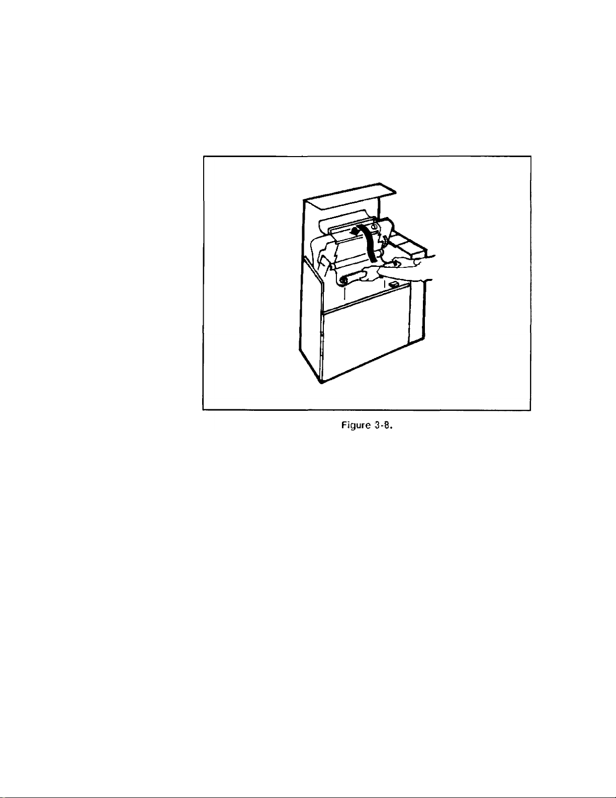
1. Place spool on retainer cups.
Open the swing-gate completely until it latches at the top. Lower the
ribbon shield and open the ribbon access cover (refer to Figure 3-4,
B). Put on the plastic gloves supplied in the ribbon box and place one
of the ribbon spools on the retainer cups as shown in Figure 3-8.
Lowering Ribbon Shield and Opening Ribbon Access Cover
3-6 PREPARING THE PRINTER FOR OPERATION
Page 28

2. Install lower ribbon spool.
Route the ribbon up and over the ribbon sensing bar (Figure 3-9,
A). Install on the lower ribbon drive hubs by sliding toward the left
(Figure 3-9, B).
PREPARING THE PRINTER FOR OPERATION 3-7
Page 29

3. Close lower access cover and ribbon shield.
Pull the lower ribbon access cover toward you to close. Lift the paper
shield up to close (Figure 3-10).
Figure 3-10. Closing Lower Ribbon Cover and Paper Shield
4. Close swing-gate and open upper access cover.
Push the swing-gate handle down to close. Open the upper ribbon
access cover by gently pulling it toward you.
3-8 PREPARING THE PRINTER FOR OPERATION
Page 30

5. Install upper ribbon spool.
Lift the ribbon spool from the retainer cups (Figure 3-11, A). Install
on the upper ribbon drive hubs by sliding toward the left (Figure
3-11, B).
6. Close the printer.
Raise the upper ribbon access cover up into the closed position and
close the printer’s top cover (Figure 3-12).
PREPARING THE PRINTER FOR OPERATION 3-9
Page 31

Paper Loading and
Adjustment
The rest of this chapter explains how to load, adjust, and position your
paper in the printer. The instructions are written in sequence, and, if
followed in order, detail the correct procedure to set up your printer for
operation.
Note
IF
When the printer runs out of paper, it completes printing the last page
and goes “off-line.” At this point, the paper is at the Top of Form
position.
1. Operator Information Label.
An Operator Information Label is located on the inside of the printer
for ea^ reference to error and configuration modes, setting forms
position and Top of Form, and other printer functions.
2. Turn the printer "ON.”
On the back panel of the printer, flip the power switch to the “ON”
(1) position. The printer must be “ON” to perform set-up functions.
Raise the printer’s top cover and open the cabinet’s front door (Figure
3-13).
3-10 PREPARING THE PRINTER FOR OPERATION
Page 32

3. Open the swing-gate.
Push down on the swing gate release lever (Figure 3-14, A) and
lift up the swing-gate by the handle (Figure 3-14, B) until the gate
latches at the top.
PREPARING THE PRINTER FOR OPERATION 3-11
Page 33

4. Open the platen.
Pull out the spring plunger knob and move the paper thickness
adjustment lever to the maximum thickness setting, “N” (Figure
3-15). This will prepare the printer for the final forms thickness
adjustment later in this chapter.
Figure 3-15. Opening Ihe Platen
3-12 PREPARING THE PRINTER FOR OPERATION
Page 34

5. Open the tractors.
Flip open the tractor lids.
PREPARING THE PRINTER FOR OPERATION 3-13
Page 35

6. Position the paper.
Position the paper supply on the floor of the cabinet so that it is all
the way forward, towards the door. Then, center it under the tractors
(Figure 3-17). DO NOT RUN PAPER FROM A BOX PLACED
OUTSIDE THE PRINTER CABINET.
Note
Paper jams can occur because the sides of the box are too close to the
paper stack. Pull the sides of the box away from the stack to let the
paper move freely through the printer.
7. Continue loading paper.
Proceed to “Adjusting Vertical Paper Tension” on page 3-15.
3-14 PREPARING THE PRINTER FOR OPERATION
Page 36

Adjusting Vertical
Paper Tension
Note -,l Make sure you adjust vertical paper tension each time you load paper.
A slight paper tension aids print quality and is impoitant for proper
operation of your printer. If the paper tension is too loose, marginal
print quality occurs. If the paper tension is too tight, paper will come
out of the tractors causing a paper jam. After you make a preliminary
tension adjustment, proceed to page 3-17 to adjust the forms position
and make the rinal adjustment.
1. Position the vertical tension lever.
Pull out the spring plunger knob and place the vertical tension lever
in the “A” position (Figure 3-18, A). Place the paper in the two left
tractorti and close the tractors.
Figure 3-18. Adjusting Vertical Paper Tension
PREPARING THE PRINTER FOR OPERATION 3-15
Page 37

2. Preliminary adjustment of vertical paper tension.
Pull out the spring plunger knob again (Figure 3-18, A) and move the
lever downward until the paper is slightly taut against the platen.
(The platen is located in the curved black surface lying between the
upper and lower tractors.) To test the tension, place your hand on the
paper over the black surface and gently push the paper up and down
(Figure 3-18, B). If the paper moves freely, the vertical tension is too
loose. When the tension is correct, you will notice only slight vertical
looseness and no paper feed hole distortion.
3-16 PREPARING THE PRINTER FOR OPERATION
Page 38

Adjusting Forms
Position
Use this procedure when you change the position of the form in the
printer, or want to set the horizontal paper tension. These insti-uctions
prepare your printer for the next step, “Adjusting Forms Thickness” on
page 3-21.
Notti
I
Too little or too much horizontal tension can cause paper jams in the
cp printer.
1. Adjust the left paper path.
With the swing-gate latched in the full open position, set the tractor
control knob to FORMS ALIGNMENT POSITION (Figure 3-19, A).
Press either of the tractor control keys (Figure 3-19, B) left or right
until the left tractors (Figure 3-19, C,D) are in the desired position
for printing the left page margin. Holding the center key down while
pressing the left or right key will increase the speed that the tractors
move.
Figure 3-19. '^ractor Conti ols
PREPARING THE PRINTER FOR OPERATION 3-17
Page 39

2. Ai^ust the right tractor.
Set the tractor control knob to the FORMS WIDTH ADJUST
POSITION (Figure 3-20, A). Only the right tractors should move; the
left tractors should remain stationary. Press the right tractor control
key to increase the forms width position (Figure 3-20, B). To decrease
the forms width position, press the left tractor control key until the
tractors are narrower than the form (Figure 3-20, B, HORIZONTAL
ADJ.).
3-18 PREPARING THE PRINTER FOR OPERATION
Page 40

3. Close the right tractors.
Insert the paper into the two right tractors and close the tractors.
Adjust the horizontal tension.
With the tractor control knob still in the FORMS WIDTH ADJUST
POSITION, fine adjust the tractor positioning by touching the right
tractor control key (Figure 3-20, B) until there is a slight horizontal
tension on the paper. When the tension is correct, reset the tractor
control knob to the PRINT AND FORMS ALIGNMENT POSITION
(Figure 3-20, C).
Note Be sure the tractor control knob is reset to the PRINT AND FORMS
^ ALIGNMENT POSITION before printing or you may have form feed
problems.
5. Final vertical paper tension adjustment.
Make sure the tractors line up vertically with the holes in the paper.
If they do not, align them by pulling out the spring plunger knob and
moving the vertical paper tension lever up or down (Figure 3-18, A).
Close the tractors. (For detailed adjustment instructions refer back to
step 2, “Preliminary Adjustment of Vertical Paper Tension,” on page
3-16.)
6. Test paper motion.
Press and hold the (line feed 1 key for several seconds to advance
paper into the powered paper stacker. Press the (form feed) key two
or three times to make sure that the paper moves freely over the
platen.
PREPARING THE PRINTER FOR OPERATION 3-19
Page 41

7. Inspect paper tractor holes.
Inspect the holes in the paper’s tractor strips that have just passed
through the tractors. They should have a slight teardrop shape
(Figure 3-21, A). If the holes show an extreme distortion (Figure
3-21, B) or the paper jams, pull out the spring plunger knob (refer to
Figure 3-18) and move the vertical paper tension lever one position
toward “A.” Press the [form feed 1 key again and re-examine the
tractor holes.
8. Proceed to "A4justing Forms Thickness."
Follow the instructions on page 3-21 to adjust the thickness setting
for your form.
3-20 PREPARING THE PRINTER FOR OPERATION
Page 42

Adjusting Forms
Thickness
The forms thickness adjustment allows the printer to accommodate
various thicknesses of paper, such as when changing from single to
multi-part forms, or when using different weights of paper. The result
of setting forms thickness correctly is optimum print quality. These
procedures explain how to correctly set forms thickness and run a
sub-test to determine best print quality.
1. Position the forms thickness lever.
If the lever is not already positioned at maximum thickness setting,
“N” (as per instruction 4 on page 3-12), pull out the spring plunger
knob and set it at this time (Figure 3-22).
'"igure 3-22. Setting the Forms Thickness Lever at Maximum Thickness
PREPARING THE PRINTER FOR OPERATION 3-21
Page 43

2. Adjust the setting for print quality.
Move the lever one or two positions at a time toward the minimum
thickness setting, “A,” and then run sub-test 15 until you find
optimum print quality.
3. Run sub-test 15:
a. Enter the TEST mode.
Push the [testI key to enter the TEST mode (two decimal points
will light up). Use either [fine adj.) key to find sub-test 15 (a
pattern of horizontal and vertical lines). Press [enter ) to start the
test.
b. Examine the print.
Use the [form feed) key to eject the page out of the powered
paper stacker. Examine the vertical lines. They should be straight.
If they are somewhat jagged, with the individual dots offset to the
right and left, this is called “dot slalom” (Figure 3-23). It signifies
that the print gap is too large (the higher the letter on the knob,
the wider the print gap). To decrease the gap, turn the forms
thickness knob one position towards the smaller letters. If the ink
is smudging on the paper, the print gap is too small; increase the
setting by turning the knob one position toward the larger letters.
ONE PACE OF PRINT
3-22 PREPARING THE PRINTER FOR OPERATION
y V
GOOD SAD
COLUMN DOT POSITIONS
Figure 3-23. Dot Slalom
Page 44

c. Return to step "1."
Continue to a(^ust the thickness setting and run sub-test 15 until
the vertical lines are straight and the best print quality is obtained.
If you are having print quality problems, see “Optimizing Print
Quality” on page 6-14 for information.
Note
When printing in draft mode, tighten the paper thickness adjustment
lever up one additional position.
4. Check overall print quality.
At this point, your printer is set-up to obtain best print quality.
Follow the instructions on page 3-24 to run sub-test 9 and examine
the printed characters.
PREPARING THE PRINTER FOR OPERATION 3-23
Page 45

Overall Print Quality
Run sub-test 9 to check the overall print quality of your printer. Inspect
the upper case characters on the printout for “character scrunch.”
1. Select sub-test 9.
Press the fTEST) key to enter the TEST mode (two decimal points will
light up). Use either [fine adj. ) key to find sub-test 9. Press [enter )
to start the test.
2. Examine the characters.
Use the [form feed 1 key to eject the page. Examine the printed
characters. They should look even and well formed. If they appear
“squatty” or “scrunched,” this is called “character scrunch,” and
indicates that the paper tension is too loose (Figure 3-24).
1
•
•
A
UNEQUAL
SPACING
___
J
•
----------------------
SPACING
'
A
PAPER TENSION
rA TOO LOOSE
Figure 3-24, Character Scrunch
D PAPER TENSION
D CORRECT
3. Adjust vertical paper tension.
To correct “character scrunch,” move the vertical paper tension lever
toward “N” one position at a time. Continue to run sub-test 9 and
adjust the setting until optimum print quality is achieved.
4. Proceed to "Adjusting Forms Length."
Turn to page 3-25 for instructions on “Adjusting Forms Length.’
3-24 PREPARING THE PRINTER FOR OPERATION
Page 46

Forms length is the amount of text lines your printer can print per page.
It can be set two ways: | inch increments or text lines-per-page. Both
methods are explained below. If you are setting forms length for the
first time, or changing forms length to a new paper size, follow these
instructions.
If you do not need to adjust the forms length, continue to the next
section, “Adjusting Top of Form,” on page 3-30.
Figure 3-25 defines areas on the form you need to consider when setting
forms length.
igure 3-25. P?rts oi the Form
PREPARING THE PRINTER FOR OPERATION 3-25
No Perf
Skip
Page 47

Adjust Physical Forms
Length in ^ Inch
Increments.
The forms length can be set in | inch increments from 2 to 16 inches. If
you want to set forms length in increments other than ^ inch, turn to
page 3-27 to acUust forms length in physical text lines-per-page.
Use the keys on the control panel to set the forms length:
1. Enter the connguration mode.
Press and hold down the f CONFIG. 1 key. At the same time, press the
[fine adj. 1 keys to move to function 7 (the decimal points indicate
the CONFIGURATION mode). Release the [CONFIG.] key. A “1” or
a “0” lights up in the display window. You want setting “0.” Press
either [fine adj. ] key to move to “0” (if “0” is already displayed, press
[ENTER P.
2. Press [enter]
This programs the printer to set forms length in | inch increments.
3. Press [page l. adj.]
Note
The current page length setting is displayed in inches. A decimal
point allows the number to be a fraction. For example, a setting of
8.5 is actually 8 ^ inches. A setting of 11.0 is 11 inches.
If you do not want to change the page length, press the [page l. adj. )
key a second time to return to the STATUS mode, or press [on line) to
return the printer to the host.
4. Change the page length setting.
Use the [fine adj. 1 keys to move to the desired page length.
5. Press [enter]
The printer returns to the STATUS mode (a “0” appears in the
display window) indicating that the desired page length is entered.
6. Proceed to "A4)usting Top of Form."
Turn to page 3-30 to adjust the Top of Form position.
3-26 PREPARING THE PRINTER FOR OPERATION
Page 48

Adjust Forms Length in
Physical Text
Lines-Per-Page.
The forms length can be set in number of printable text lines-per-page.
The printer can be set at 6 LPI (lines-per-inch), to print 12 to 96 lines of
physical text per page, or 8 LPI, to print 16 to 128 lines of physical text
per page. It can also be set to operate with perforation skip “ON” or
“OFF.” To adjust forms length in physical text lines-per-page, you must
set perforation skip, LPI, and forms length in this order.
Set Perforation Skip.
Perf (perforation) skip provides a 1 inch vertical margin that, when
properly positioned via the Top of Form setting, prevents printing on the
perforated line.
Example:
When printing an 11 inch form at 6 LPI with perf skip “OFF,” 66 lines
will be printed with no margin allowed for the perforation. When perf
skip is “ON,” the text length is limited to 60 lines, thus allowing for a
1 inch vertical margin. If Top of Form is set to begin printing 1 inch
below the perf, the next perf will be centered within the 1 inch margin.
At 8 LPI, the maximum text length would be reduced from 88 to 80
lines (refer to Figure 3-25).
Turn perf skip "ON."
The perf skip default setting for your printer is “OFF.” To turn perf skip
“ON,” follow these instructions:
1. Enter connguration function 60.
Press and hold down the (config.) key. At the same time, press
either (fine adj. ] key to move to function 60 (the decimal points
indicate the CONFIGURATION mode). Release the (config.) key. A
“0” lights up in the display window.
2. Change to "1."
Use either (fine adj. ] key to move to “1.”
3. Press (enter 1
This turns perf skip “ON.”
Turn perf skip "OFF."
Follow steps 1, 2, and 3 above, but enter “0” instead of “1.’
PREPARING THE PRINTER FOR OPERATION 3-27
Page 49

With perf skip “OFF,” the printer will print whatever number you enter
for physical text lines-per-page. If the number exceeds the maximum
physical lines the printer can print per page, it will print in the perf skip
region.
For more information on perf skip, refer to the section on “Perforation
Skip Mode” in the HP256X Printer Family Technical Reference Manual,
02564-90905.
Note Perf skip mode is only applicable when using line feed instruction
“ applications fline count). If the application uses calls to Vertical Forms
Control (VFC) channels, the VFC definition Of vertical margin is used
and the state of the perf skip mode has no effect.
Set LPI (lines-per-inch).
Once you have determined the perf skip mode, the next step is to set
LPI.
1. Press (L.P.I. ADJ.l
The present LPI setting shows up in the display window (the decimal
points indicate the CONFIGURATION mode).
2. Change the LPI setting.
If you want to change the value, use either [fine adj. ) key to move to
the desired LPI setting (both keys toggle between 6 and 8). If you
do not want to change the value, press the fu.P.i. adj.) key again to
return to the STATUS mode (a “0” appears in the display window)
and proceed to set the forms Ic/igth.
3. Press [enter]
The printer returns to the STATUS mode (a “0” appears in the
display window) indicating that the desired setting is entered.
3-28 PREPARING THE PRINTER FOR OPERATION
Page 50

Set forms length.
After determining the LPI setting, use the keys on the control panel to
set the forms length:
Nok
I-;?:
If you set forms length in programmable Vertical Forms Control (VFC),
make sure the same setting is entered in the front panel. Otherwise, the
printer will continue to print when paper-out occurs.
1. Elnter the configuration mode.
Press and hold down the fcoNFiG.) key. At the same time, press
either (fine adj.1 key to move to function 7 (the decimal points
indicate the CONFIGURATION mode). Release the fcoNFiG.) key.
A “1” or a “0” lights up in the display window. You want setting
“1.” Press either (fine adj. 1 key to move to “1” (if “1” is already
displayed, press [enter]).
2. Press [enter]
This programs the printer to set forms length in lines-per-page.
3. Press [page l. adj ]
The current number of text lines-per-page is displayed.
iMOtf
I If you do not want to change the text lines-per-page, press the
[page l. adj.] key a second time to return to the STATUS mode, or press
[on line] to return the printer to the host.
4. Change the setting.
Use either [fine adj. ] key to move to the desired number of text
lines-per-page.
5. Press [enter]
The printer returns to the STATUS mode (a “0” appears in the
display window), indicating that the desired page length is entered.
6. Proceed to "Ac^usting Top of Form."
Turn to page 3-30 for instructions on “Adjusting Top of Form.’
PREPARING THE PRINTER FOR OPERATION 3-29
Page 51

Adjusting Top of
Form
Noie -.1 In order to set Top of Form, the swing-gate must be open and latched at
The Top of Form (TOF) position is an arbitrary indicator of the first
line of print. Once the Top of Form is set, any succeeding (form feed)
advances paper one page length until the same position on the next page
is reached. This enables you to move swiftly to the first print line on the
succeeding page.
Adjust Top of Form using the keys on the Operator Control Panel.
^ the top. The number 10 will flash in the display window indicating that
the swing-gate is open; however, disregard this message for now.
1. Adjust the paper.
Use the fuNE feed 1 or [fine adj.1 keys to adjust the paper so the
paper perforation is directly over the metal platen strip (Figure 3-26).
Pialen MetalStrip
3-30 PREPARING THE PRINTER FOR OPERATION
Figure 3-26. Adjusting Paper Over the Platen
Page 52

2. Lower the paper shield.
3. Ac^ust horizontal forms alignment.
The numbers on the paper shield (Figure 3-28) are indicators to
determine your first column of print. Set the tractor control knob to
the FORMS ALIGNMENT POSITION (Figure 3-19, A) and move the
left tractor control key (Figure 3-19, B) to position the paper to the
first column of print.
Figure 3-28. Positioning Paper to the First Column of Prin:
PREPARING THE PRINTER FOR OPERATION 3-31
Page 53

4. Press fSET T.O.F. 1
Three decimai points in the display window illuminate to indicate the
SET T.O.F. mode.
5. Press [enter 1
This sets the new Top of Form position and returns the printer to the
printer ready STATUS mode.
6. Close the swing-gate.
7. Verify the Top of Form position.
Use the (testI key and (print i line) key to determine if the Top of
Form setting is correct. If not, repeat step 1 on page 30 to adjust your
paper to the desired position.
If a paper-out error was in effect before the (set t.o.f. ) key was pressed,
setting the Top of Form clears the error.
3-32 PREPARING THE PRINTER FOR OPERATION
Page 54

Top of Form Alignment Guide Labels
These labels provide easy alignment of frequently used forms. They are
provided with each printer; however, additional sheets (02566-00223)
may be purchased through your Hewlett-Packard Sales offices.
ALIGNMENT GUIDE LABELS
____1__
I I I M I M I M
INDEX
TOF
"index
ig ir 3-29. "op I j in / itir (
PREPARING THE PRINTER FOR OPERATION 3-33
Page 55

Installing the Top of Form Alignment Guide Labels
1. Position the index label.
Peel off the index label from the plastic sheet (Figure 3-30) and
adhere it to the left hand print mechanism cover above the “Forms
Loading/Ribbon Replacement” label.
INDEX
A
B
c
D
E
F
G
H
1
J
K
L
M
N
RECORD "TOF*
INFORMATION
■ FOR FORMS
SEING USED.
Fióte
It is recommended that alignment guide labels be placed only on the
upper viewing surface so that paper position can be viewed with the top
cover closed. Do not place labels on the platen surface, under the paper.
3-34 PREPARING THE PRINTER FOR OPERATION
Figure 3-30. Top of Form Index Label
Page 56

2. Position the alignment guide labels.
After your form is in position, place an alignment guide label (A, B,
etc.) next to the perforation on the rear paper guide (Figure 3-31).
Make sure the label is positioned so it can be seen when using
various paper sizes.
Figure 3-31. Positioning Alignment Guide Labels
PREPARING THE PRINTER FOR OPERATION 3-35
Page 57

3. Record information.
Write down form placement information on the index label (Figure
3-32).
INDEX
A
BANK CHECKS C
9.5 X 11 INVENTORY D
B
CARD LABELS A
C
INVOICE FORMS E
D
E
F
G
■ BEING USED-
H
RFCORO -TDF*
information
~ FOR FORMS
1
_J_
K
L
M
IT
Fiaure J-3Ì'.
Noie If form alignment information changes, record the new form placement
on the index label.
3-36 PREPARING THE PRINTER FOR OPERATION
di ' = I iloi
Page 58

USING THE POWERED PAPER STACKER
For optimum performance of your powered paper stacker, follow these
instructions to correctly use the stacker and position your paper.
NotP „,i An Operator Information Label is located on the inside panel of the
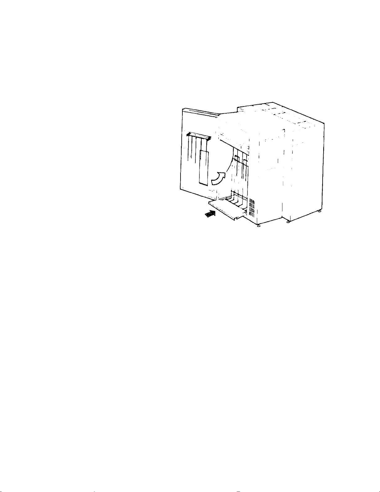
y powered paper stacker to provide brief instructions on how to use your
stacking aid.
1. Open the stacker door.
Slide out the paper tray and place the chains behind the backstop
(Figure 4-1).
4
figure i. Sliding Oul Ihe P<iper Tray
USING THE POWERED PAPER STACKER 4-1
Page 59

2. Position the backstop.
The two labels on the paper tray show you where to position the
backstop for different paper sizes. Refer to Table 4-1 for the correct
placement for your paper size and then install the backstop at the
desired location on the paper tray (Figure 4-2).
Figure 4-2. Positioning the Backstop
4-2 USING THE POWERED PAPER STACKER
Table 4-1. Recommended Backstop Positions
Form Size (width x length)
14 g X 12 inches
14 1 X 11 inches
Single Part Multi-Part
E D
E E
9 g X 11 inches E
8 1x11 inches (3 hole) E
11 X 8 1 inches G F
8 1 X 7 1 inches I H
E
E
Page 60
3. Push in the paper tray.
Make sure the chains hang in front of the backstop (Figure 4-3).
Figure 4-3. Pushing In the Paper Tray
USING THE POWERED PAPER STACKER 4-3
Page 61

4. Adjust the door chains.
Refer to Table 4-2 for the recommended position of the door chains
for your paper size. (The Operator Information Label, inside the
stacker, also diagrams door chain positions.) To install the chain
assembly on the stacker door, turn the metal bar sideways to fit into
the bracket; then, insert the chain assembly into the desired slot
(Figure 4-4).
4-4 USING THE POWERED PAPER STACKER
Figui v ' Arliiiiiiirin uoor Ciiaiiis
lule 2. Rerr ;irui ndet De ■ '<
Form Size (width x length)
14 1 .\ 12 inches
14 1 X 11 inches
Single Part Multi-Part
B
C
9 1 X 11 inches B A
8 i X 11 inches (3 hole)
11 X 8 i inches
8 j X 7 1 inches
B
F D
F
A
A
A
E
Page 62

5. Advance paper into the stacker.
Start your job to advance at least 10 sheets of paper onto the paper
tray (make sure the first form feeds smoothly into the stacker without
jamming).
6. Start the paper stack.
Make sure each form folds on the tray the same way as it came out of
the input box (Figure 4-5).
•-! jn. 1-5. SI.:- ini
Sia: k
The performance of the stacker depends on the paper folding correctly.
It is extremely important for the paper to fold the same way it was
manufactured.
USING THE POWERED PAPER STACKER 4-5
Page 63

7. Align the paper stack.
Center the stack directly under the falling paper and then push it
against the backstop (Figure 4-6). The backstop guides the paper into
position and helps it fold correctly.
8. Cluso the stacker door.
Continue to peige 4-7, “Unloading the Paper Stack,” for information
on how to remove paper from the stacker.
4-6 USING THE POWERED PAPER STACKER
Figure 4-6. Aligning the Paper Stack
Page 64

Unloading the Paper
Stack
When you run out of paper in the printen
1. Advance paper into the stacker.
Put the printer “off-line” and press [form feed 1 to advance the last
sheets of paper into the stacker.
2. Remove the stack.
Slide the paper tray out and pick up the stack.
3. Close the stacker.
Push the tray back in and close the door.
When you Hnish one job and want to start anothen
1. Put the printer "off-line."
Push the fON line) button to take the printer “off-line.”
2. Pull out the paper tray.
3. Remove your job.
Tear off the last sheet from your job and remove it from the paper
tray.
4. Prepare the stacker for the next job.
Adjust the backstop and door chains for your next forms length.
5. Push the paper tray back in.
6. Push the [on line) key to put the printer turn the printer "ON."
7. Start your new job.
Return to the stacker and make sure the forms are folding and
stacking correctly.
8. Close the stacker door.
USING THE POWERED PAPER STACKER 4-7
Page 65

4-8 USING THE POWERED PAPER STACKER
Page 66

The HP2566C/HP2567C printer needs to be configured to perform
various functions. Follow the procedure below, to configure your printer
using the buttons on the Operator Control Panel.
Table 5-1 lists the configurable printer functions and their associated
numbers. Each function has two or more possible parameters that can
be selected as desired. Some of the functions can be set remotely via
escape (ESC) sequences. See the HP256X Printer Family Technical
Reference Manual, 02564-90905, for information about remote
configuration. Also, use the Operator Information label, inside your
printer, as a quick reference guide for the CONFIGURATION modes.
Follow steps 1 - 4 to atyust and set CONFIGURATION modes from the
Operator Control Panel.
5
1. Enter the CONFIGURATION mode.
Make sure the printer is “off-line.” Press and hold down the
(CONFIG. 1 key. At the same time, press either (fine adj. ) key to move
to the desired function number (two decimal points indicate the
CONFIGURATION mode).
2. Release the (config.1 key.
The parameter value for the desired function number shows up in
the display window.
If you do not want to change the parameter, press the (config. ) key a
second time, or press the [enter) key, or press the (on line] key. All
these retain the original configuration for that function.
3. Set the parameter.
Use the (fine adj ) keys to move to the desired parameter.
PRINTER CONFIGURATION 5-1
Page 67

Some configuration parameters can only be modified by a
^ Hewlett-Packard Service Representative. In these cases, the (fine adj, )
keys have no effect.
4. Press [ENTER 1
This sets the new parameter and the printer returns to the STATUS
mode.
Table 5-1. Configuration Function Numbers
Parameter
Function #
Description
Range
Comments
1
2
Select Primary Character Set 0-95 See pg. 5-3
Select Secondary Character Set 0-95
7 Select Page Length
Representation
20-29* Configure Interface
50
51
Disconnect Modem
Difficult Forms Mode
52 Horizontal Graphics Density
60 Perforation Skip 0,1
61 Display Functions
80 Enable/Disable Label Card
81 Printronix P-Series Line Feed
Emulation
85-89
Configure Label Card
See pg. 5-3
0,1
See pg, 5-4
00-FF See pg. 5-5
0.1
0,1
60,70
See pg. 5-4
See pg. 5-4
See pg. 5-4
See pg. 5-5
0,1
0,1
See pg. 5-5
See HP Label
Card Manual
26062-90902
0,1
See HP Label
Card Manual
00,FF
See HP Label
Card Manual
5-2 PRINTER CONFIGURATION
• Functions 20-29 are dependent on which interface is installed (see your
Interface manual)
Page 68

Character Set Selection
To be compatible with both 7-bit and 8-bit hosts, your
HP2566C/HP2567C has 7-bit and 8-bit character sets. The standard
7-bit sets are ASCII and Roman Extension. The standard 8-bit set is
Romans, combining ASCII plus Roman Extension characters. The
printer may contain up to 16 character sets. Your printer contains the
sets which were speciHed in your purchase order. Two character sets
(primary and secondary) may be selected at any one time and are chosen
either through the CONFIGURATION mode from the Operator Control
Panel or remotely via escape sequences.
Primary Character Set: FUNCTION 1
Select the primary character set by accessing function number “1” of
the CONFIGURATION mode and selecting the parameter associated
with the desired primary character set. The character sets and their
associated parameters are listed on your self-test print out. Figure 5-1
shows an example of the top portion of a self-test printout. The arrows
in the figure point out the assigned character set parameter value.
Note that the assigned values vary from printer to printer. Check your
printer’s self-test to find the character set values.
Secondary Character Set: FUNCTION 2
Select a secondary character set from the printer’s self-test. Access
function number “2” of the CONFIGURATION mode and enter the
parameter associated with that set (Figure 5-1).
CONTROL RONRD tCRC E7(l6t ST I 3
HR-ie INTCRRACE £33R
IL gp. ..«,» ? I n
► IT
►ai
Id Û CPI—HICH DCriStTT
►a« [)»■
► as !"**«■ {)*•
► a* iWVriim'i'.Vp'iWW'iSl.lWW.VWil'l ''Pi*<' Ci
"igurr 5-1. Chsrarirr Sc! SofJ ’"Dît rsmrip''
PRINT TINE OOOOOi HOURS
HP-19 DEVICE ADDRESS < 4.
AtttPt i t(iUd(itiD«>3i{
tsos
FREHCH=4S| eERHAN-A*. SUEDI 3H/FIHHI EH-SO , DAN ISH/MOHUEO 1 Alf-S
I *•!);» ’ H.» .- ./BieiASSTOS; , <■ > ?#ABCDEFCHt JKLHH0P0R3TUVUXT11\3
AACUII' - - 'tict'T r Cera I ittf «) if AAA* saataa At 1(01 **A iodé: DOARU
■ n.xju* -ajLn I m pu« \ < r.J r ^ ut
/1 |R!«r«3Hrr>*E>< ■ ■DAaJtIlal#A<9L«LaauavArv*rTtA*X<'C*->ri-l<oA*
at i e n ■ -
fS O S rflCMi-PJ .
■ /DiaSHStTaN ; i s*>fSABCICFCHIJELI1N0P0RSTlJWiXYZE\l»VtIabc
n*.- /otaiRSSTES; : <->?|aBC0EFCHI JRLHNOPOH3TuvUxrZt\J-_-ai)c
OÌMMAIfTa, STIXDISil/riM»JSg-tff , , SPA),
/01¡3*56780:;<=>TS*0CDEF6HlJKLHNOPaaSTUVU*YZC\3‘ 'abt
OH IIHE Odi 0*9 HOURS
CIRER PROTOCOL
1
. SPAT
*Sa~ tÿ*ÇçStii *11/*//A4* /R4*/iLà*l'BÂ**u/i*irO\.#caliOR/ï** i ïâ/
^DAAÍ ftàAÎMÙiivkAi^àér-AAÎAÊAitaA I OR/i*/A13/
/ÎI/14/CT/« ;t‘‘iJ«A»CDirOaiJKlManrBllSTt/ViltTtr\l-^'_'aH!L
PRINTER CONFIGURATION 5-3
Page 69

Remote Character Set
The character sets shown in your self-test printout may also be selected
remotely if performed under program control. Character set selection
commands override the Operator Control Panel configuration setting
(except under power-on or reset conditions). When taken “off-line,”
the printer remains in the character set last commanded. See the
HP256X Printer Family Technical Reference Manual, 02564-90905, for
information on remote character set selection.
Standard ASCII SHIFT-IN and SHIFT-OUT codes may be used to select
primary and secondary character sets. SHIFT-OUT selects the secondary
set and SHIFT-IN returns the printer to the primary set. Any number
of character sets may be used within one print line if they are the same
pitch. Additionally, bar codes and line draw can be printed on the same
line as 10 character-per-inch (cpi) character sets. (Compressed character
sets and the double-high/double-wide character set cannot be printed on
the same line with each other or with 10 cpi text.)
Select Page Length
Representation:
FUNCTION 7
Disconnect Modem:
FUNCTION 50
Difficult Forms Mode:
FUNCTION 51
Horizontal Graphics
Density Selection:
FUNCTION 52
Page length can be selected in either lines-per-page or in ^ inch
increments. Refer to “Adjusting Forms Length” on page 3-25 for
instructions on how to set the CONFIGURATION mode.
If a serial interface is installed in the printer and is connected to a
modem, it is possible to disconnect the modem from the printer’s
Operator Control Panel. Setting function 50 to parameter “1” and then
pressing (enter! makes the Data Terminal Ready line to go to the
“OFF” state for two seconds. If the modem Data Terminal Ready line is
connected, this action should disconnect (hang-up) the modem.
Some complex multi-part forms such as statement mailers or invoices
may result in a loss of the Top of Form position. If this problem occurs,
the printer can be placed in a low speed, high torque mode by accessing
function 51 of the CONFIGURATION mode and selecting parameter
“1.” Since this will affect throughput, make sure function 51 is set back
to “0” when the high torque mode is not required.
Horizontal graphics density (60 or 70 dots per inch) is selected via
function 52. There is not a parameter “1” or “0” for this function. Only
60 or 70 shows up in the display window. Programmatically setting
the density overrides the operator control panel setting except under
power-on or reset conditions. Default value is 70 dots-per-inch (dpi).
5-4 PRINTER CONFIGURATION
Page 70

Perforation Skip Mode:
FUNCTION 60
When perforation skip mode is enabled (ON), an automatic page eject
occurs when the perforation skip region is entered. This is to prevent
printing too close to the page perforations. You can turn this automatic
page eject “ON” by setting Perforation Skip Mode (function 60) to
parameter “1” (ON). The default value is “0” (OFF). VFC control is not
affected by perforation skip mode. For more information on perforation
skip, refer to page 3-27.
Display Functions
Mode:
FUNCTION 61
Vertical Line Spacing
Turn on the display functions mode by setting function 61 to
parameter “1” (ON). In the display functions mode, the printer prints
representative character ^mbols for the control code or escape sequence
characters instead of actually executing the commands. For example,
if the printer encounters the SHIFT-OUT command (to access the
secondary font), the command will not be executed. The symbol Sq
will be printed instead. Two exceptions to this are the carriage return
command and the escape sequence to turn display function mode
“OFF” (ESC Z). The carriage return control character will cause a
symbol to be printed and an actual carriage return and line feed to be
performed. Function 80 must be set to parameter “1” if the display
function mode is “ON.” The default parameter for display functions
mode is “0” (OFF).
Vertical line spacing (6 or 8 lines-per-inch) is selected via the fL.p.i. adj. )
key on the Operator Control Panel or by program control or escape
sequences. Programmatically setting the line spacing overrides the
Operator Control Panel setting except under power-on or reset
conditions. Refer to page 3-28 for more information on setting LPl.
Interface
Configuration
Note
All interface functions are programmed from the Operator Control
Panel, however, your Hewlett-Packard Service Representative usually
enters these numbers. When the function numbers are entered,
make sure you write them down for futiu:e reference. There may
be instances when these numbers need to be re-entered. Each interface
has its own set of configuration parameters which are set by accessing
functions 20 through 29 of the CONFIGURATION mode. If you need
additional information, refer to the Interface manual shipped with your
printer for configuration or cabling information.
If your printer is equipped with an HP-IB interface, see page 5-6 for
HP-IB Address Selection. If it is equipped with another interface, see the
Interface manual shipped with your printer.
PRINTER CONFIGURATION 5-5
Page 71

All interface functions (20 - 29) and their parameters must be entered. If
you need to change the configuration or re-enter numbers, follow this
procedure:
1. Enter CONFIGURATION mode.
Make sure the printer is “off-line.” Press and hold down the (config.)
key. At the same time, press either (fine adj.) keys to move to
the desired function (20 - 29). Two decimal points indicate the
CONFIGURATION mode.
2. Release the (config. 1 key.
Find the parameter for the function (20 - 29) in the Interface manual
that was shipped with your printer, or if you wrote down the
configuration parameters when your interface was installed, use those
parameters.
3. Set the parameter.
Use either (fine adj.1 key to move to the desired parameter number.
4. Press(enter 1
This sets the new parameter and the printer returns to the STATUS
mode.
5. Set the next parameter.
Repeat steps 1 through 4 until all the parameters for functions 20
through 29 are entered.
When selecting an HP-IB address, use the same basic procedure as
configuring other printer features such as character set selection and
print density. To select an HP-IB address, follow this procedure:
1. Enter CONFIGURATION mode.
Make sure the printer is “off-line.” Press and hold down the (config.)
key. At the same time, press either (fine adj.) key to move to
function 20. The two decimal points indicate the CONFIGURATION
mode.
2. Release the (config.) key.
The current HP-IB address shows up in the display window.
3. Set the parameter.
Use the (fine adj. ) keys to move to the desired address (0-7).
4. Press(enter)
5-6 PRINTER CONFIGURATION
This sets the new address and the printer returns to the STATUS
mode.
Page 72

fsjote
I
The HP-IB cable loading is set at the factory to match a single cable
length appropriate for the interface option selected. To match the HP-IB
loading to a different length cable, call your Hewlett-Packard Service
Representative.
Test
Standard Self-Test
Note ^ After you press the (test) key to start a self-test, it takes a few seconds
A self-test is used to verify the printer’s operational status. This self-test
function can either be run from the Operator Control Panel or remotely
using escape sequences. See the HP256X Printer Family Technical
Reference Manual, 02564-90905, for details. You can run the standard
self-test or choose a speciric sub-test (individual sub-tests can only be
executed from the Operator Control Panel). It is also possible to have
the standard self-test or any of the sub-tests run continuously.
The printer must be “off-line” (“on-line” light not illuminated) to
execute a self-test from the Operator Control Panel. If any error number
appears in the display window, the self- test will not print.
To perform the standard self-test (excluding interface tests), depress
the (TEST I key once to enter the TEST mode and then press (enter 1 to
begin the test. To run a continuous standard self-test, press and hold
down the (test) key for more than two seconds (until the number “4”
appears in the display) and then press (enter ]. You can exit a self-test
any time by pressing either the (test) or (on line) key.
before the printer starts to print. While the self-test is running, the
right decimal point blinks in the display window.
In the back of this manual there is a simulated copy of a standard
two-page self-test printout. This printout lists power-on time and print
time in hours; interface configuration information; the date code of
some printed circuit assemblies; all the printer’s installed character sets,
bar codes and graphics; and various characters to check print quality.
The graphics part of the self-test is printed in the density set from the
Operator Control Panel.
When the test is complete and there are no errors, the printer returns to
the STATUS mode. If an error occurs during the test, an error number
flashes in the display window. Refer to page 5-9, “Test Failure,” for
more information.
PRINTER CONFIGURATION 5-7
Page 73

Continuous Test
To run a continuous self-test, press the fjEST 1 key and hold it down
for more than two seconds until the display changes from “5” to
“4.” Release the (test] key and press [enter j. The self-test will
run continuously. Exit the continuous test by pressing the [test ) or
[on lineIkey.
Specific Sub-test
Selection
Individual sub-tests can be selected and run from the Operator Control
Panel. Table 5-2 lists the sub-tests available for your printer. To run
a sub-test, press the [test! key to enter the TEST mode. A sub-test
number appears in the display window and the right decimal point
lights up indicating that the printer is in the TEST mode. Use either
[fine ADJ.I key to move to the desired sub-test number. Once the
number is displayed, press [enter] to start the sub-test.
Table 5-2. Sub-Test Numbers
Sub-Test
Standard Self-Test
Standard Ripple Print
Double Size Ripple Print
Compressed Ripple Print (16.7 cpi)
High Density Ripple Print (optional)
Raster Graphics (herring bone)
High Density Raster Graphics (herring bone)
Numbers
0
1
2
3
4
5
6
5-8 PRINTER CONFIGURATION
Printer Configuration print-out
8
900/1200 LPM Ripple Print (upper case) 9
High Speed Draft Ripple Print (upper case)
Flight time/forms thickness adjust patterns
10
15
Interface tests 30-38
Gmphics tests (if installed)
40-48
Page 74

Example of a Continuous Sub-Test
To continuously run the “Standard Ripple Print” sub-test, follow the
proceeding instructions:
1. Enter CONTINUOUS TEST mode.
Press the (test 1 key and hold it down for more than two seconds
until the displayed number “5” changes to “4.” Release the (test 1
key.
2. Select the Ripple Print sub-test.
Press either (fine adj. 1 key until number “1” is displayed.
3. Press (enter!
This begins the sub-test. Unless an error occurs, the sub-test will run
continuously. Press the (test) key to stop the sub-test or (on line) to
return control of the printer to the host.
Test Failure
If there is a problem with the printer, an error number flashes in the
display window. Error numbers indicate the general area in the printer
where the failure occurs. If your printer fails the self-test, refer to
Chapter 7 for a description of error codes or the Operator Information
Label inside your printer.
PRINTER CONFIGURATION 5-9
Page 75

5-10 PRINTER CONFIGURATION
Page 76

USING THE PRINTER
This chapter explains the various features of your printer: status mode,
Operator Control Panel, indicator lights, and print quality.
Your printer is controlled either through the Operator Control Panel,
control codes or escape sequences. This manual only explains the
Operator Control Panel. Refer to the HP256X Printer Family Technical
Reference Manual, 02564-90905, for information on control codes.
6
Printer Modes
The HP2566C/HP2567C printer operates in four modes: STATUS,
TEST, CONFIGURATION, and SET TOP OF FORM. Decimal points
show up in the display window to indicate the mode (Figure 5-1).
The numbers that display in each mode are listed in these sections of
the manual: “Printer Status” (page 6-2), “Test” (page 5-7), “Printer
Configuration” (page 5-1), and “Adjusting Top of Form” (page 3-30).
USING THE PRINTER 6-1
Page 77

Printer re
Under most conditions, the printer is in the STATUS mode and displays
its current status in the Operator Control Panel display window. When
in the STATUS mode, none of the decimal points on the display are
illuminated but a status number is displayed. This number corresponds
to a speciric status described in Table 6-1.
Moie When the printer is in the SET TOP OF FORM mode, printer status is
ijp still displayed, but all three decimal points are illuminated.
Table 5-!. r
Status
Code
Description
0 Printer ready (also modem disconnected
or serial interfaces)
1 Printer ready, modem connected (serial interface)
Silent run-data recovery for HP-IB
2
interfaces on HP 3000
4 Performs a sub-test in continuous mode
(continuous test active)
5 Performs a single pass sub-test (single test active)
Print One Line (file data) activated
6
7
Print One Line (test pattern) activated
Operator Correctable Problems
10 Swing-gate open
11 Printer out of paper
12 Ribbon jam
Paper jam
13
Error numbers 14 through 91 indicate run time or self-test errors and
are explained in Chapter 7.
6-2 USING THE PRINTER
Page 78

0;s section explains the location and function of the printer controls
and indicators.
A - OPERATOR CONTROL PANEL - (See Figure 6-3)
B = TOP COVER
C = FRONT DOOR
D = SWING-GATE
E = I/O PORT
F = POWER (ON/OFF) SWITCH
G = POWER SUPPLY INPUT
Figure 6-2. Parts oí Uie Printer
USING THE PRINTER 6-3
Page 79

Figure 6-3 shows the keys on the Operator Control Panel.
ON LINE
SET
T.O,F
TEST 1
CONnG, LP.t.
ENTEB 1
1
ON LINE J
FORM PRINT 1
FEED
LINE
FEED
LINE J
IBB
• •
ADJ.
PAGEL
AOJ.
1
FINE
ADJ- -=^
6-4 USING THE PRINTER
Figure 6-3. Operator Control Panel
Page 80

ON-LINE INDICATOR
This yellow dot lights up in the display window when the printer is
“on-line.” When the foN line) key is pressed, control of the printer is
turned over to the host and all other keys are disabled. The operator no
longer controls the printer, the computer does.
DISPLAY WINDOW
The display window is located on the top portion of the Operator
Control Panel (refer to Figure 6-3). The numbers that display in the
window convey information for the different modes: STATUS, TEST,
CONFIGURATION, and SET TOP OF FORM. The decimal points
indicate which mode the printer is in: no decimals are present when you
are in the STATUS mode; the right decimal shows up when you are in
the TEST mode; the middle and right decimals show up when you are in
the CONFIGURATION mode; and all three decimals show up when you
are in the SET TOP OF FORM mode.
Usually the printer is in the STATUS mode and displays a number
indicating what the printer is doing. Refer to Table 6-1 for status code
numbers and their descriptions.
When in the TEST mode, the number in the display window is the
number of the sub-test that you want to run. When a test is running,
the right decimal point blinks. (Refer to page 5-7 for more information
on the TEST mode.)
When you want the printer to perform different functions (change
character sets, turn perforation skip “ON” or “OFF”, etc.) you must
be in the CONFIGURATION mode. (Refer to page 5-1 for more
information).
In the TEST and CONFIGURATION modes, you can change the
numbers in the display by using the up and down (fine adj. ) keys.
SET TOP OF
FORM KEY:
(set t.o.f.1
For information on how to SET TOP OF FORM, refer to page 3-30.
This key sets the first line of print on your page. When pressed, all
three decimal points light up in the display window indicating the SET
TOP OF FORM mode. Refer to page 3-30 for details on operation of
this key. If you want to exit this mode without making changes, press
the
(set t.o.f. 1 key once again to return to the STATUS mode, or the
(on lineI key to return the printer to host control.
USING THE PRINTER 6-5
Page 81

If a paper jam error occurs, press (set t.o.f, 1 then (enter ) to clear
it. A “0” will show in the display window, however, the error will be
displayed again if the condition is not corrected before exiting the mode.
To clear a paper jam error, press the (set t.o.f. 1 key. See “Adjusting
Top of Form” on page 3-30 for more information.
CONFIGURATION KEY:
(CONFIG.)
LPI ADJUST KEY:
(l.p.i. adj.)
This key, in conjunction with the (fine adj. 1 keys, lets you enter the
CONFIGURATION mode. The CONFIGURATION mode is where
you program the printer to perform various functions (interface
configuration, page length representation, select character sets, etc.).
Pressing the
(comfig 1 key alone will do nothing.
When the (config. 1 key is held down, a function number is displayed.
This number can be changed by using either (fine adj.) key to move to a
new number. The middle and right decimal points light up to indicate
that you are in this mode. When the (config. ] key is released, the
parameter associated with the function just displayed appears in the
display window. If you wish to change parameters, use either (fine adj. )
key again to select a new parameter. Press (enter 1 to store the new
parameter and exit the CONFIGURATION mode.
If you do not want to change any parameter, press the (config. ) key a
second time and the printer returns to the STATUS mode. You can also
press the (on line) key to return the printer to host control.
For more information on printer configuration, refer to page 5-1.
Pressing this key shows the printer default LPI (lines-per-inch) setting
(6 or 8) in the display window. Since LPI is a function you can select,
two decimal points light up indicating you are in the CONFIGURATION
mode. Lines-per-inch can only be set to 6 or 8. Press either (fine adj. )
key to toggle between the two settings. When the desired setting is
displayed, press the [ enter ] key to store the value. If you do not want to
change the LPI setting, press (enter) to return to the STATUS mode or
the (on line) key to turn control over to the host. One additional note is
that this setting may be overridden by escape sequences. For more
information on setting LPI, refer to page 3-28.
TEST KEY: Press this key to enter the TEST mode where you can select sub-tests
6-6 USING THE PRINTER
(test ) ^ check printer performance. To run a sub-test, press (test 1, find the
desired sub-test with either [fine adj. 1 key, and then press (enter ).
The sub-test will begin to print. Test failure is indicated by a flashing
error number in the Operator Control Panel display window. A detailed
description of the test function is presented on page 5-7.
Page 82

ENTER KEY:
(enter)
When in the CONFIGURATION mode, pressing the (enter) key stores
the selected parameter. When the (enter) key is pressed in the TEST
mode, the printer starts running a test. In the SET TOP OF FORM
mode, pressing the (enter) key sets the new Top of Form (then the
printer returns to the STATUS mode).
PAGE LENGTH
ADJUST KEY:
(page l. adj.)
ON LINE KEY:
(on line)
This key displays the physical forms length in either physical text
lines-per page, or in | inch increments. Although the printer is in the
CONFIGURATION mode, usually one decimal point lights up (for
example, 11.5 for 11 ^ inches). You can adjust the forms length setting
by pressing either [fine adj.) key to select the value, then press [enter )
to store it and return to the STATUS mode. Refer to page 3-25 for more
information on acyusting forms length. If you use programmable VFC
to set the page length, the page length setting on the panel must
match the VFC setting, otherwise the printer will not properly
sense paper-out.
This key gives control of the printer to the operator (“off-line”) or to
the computer ^stem (“on-line”). A yellow dot lights up in the display
window when the printer is “on-line.” The keys on the Operator
Control Panel only work when the printer is “off-line.” Press (on line)
to exit from the CONFIGURATION, TEST, SET TOP OF FORM, LPI
Adjust and Page Length Adjust modes. The printer saves the previous
configuration and Top of Form setting, and turns control over to the
host. Pressing [on line) when running a self-test aborts the test and
turns control over to the host. The printer will not go “on-line” if there
is an error condition present.
LINE FEED KEY:
(line feed)
FORM FEED KEY:
( form feed1
When the [line feed) key is pressed, the printer advances to the next
print line. If you hold down the key, the printer pauses momentarily
then advances paper at an increased rate. As long as you hold down
the key, it will advance paper. The (line feed ) key functions only when
the printer is “off-line” and will not work in the CONFIGURATION or
TEST mode.
This key advances the paper to the next Top of Form position. If pressed
once, the printer moves one form feed. If you hold down the key, the
printer performs continuous form feeds. This key functions only when
the printer is “off-line” and will not work in the CONFIGURATION or
TEST mode.
USING THE PRINTER 6-7
Page 83

PRINT 1 LINE KEY:
(print 1 LINE 1
This key prints one line of data on the installed form at the current line
position. If you hold down the key, the printer prints continuous lines of
data.
I If you print a single line and want to look at it, press the line feed key to
advance the paper so that the line is visible. This is not necessary when
printing multiple lines.
The (print 1 line! key produces different data depending on the printer
mode. If the printer is in the TEST mode and you press (print i line ),
status mode 7 displays and a test pattern prints that aid forms
alignment. If the printer is not in the TEST mode, the printer goes
“on-line” momentarily, displays status mode 6, prints one line of data,
then returns “off-line.” If no data is available from the interface or host
within 1 I seconds, the printer returns “off-line” vrithout printing.
FINE ADJUST
(UP/DN) KEYS:
(fine ADJ. 1
FORMS LOADING
CONTROLS
The two (fine ADJ. 1 keys move the paper up or down in small
increments. When either key is held down, the printer keeps moving the
page until the key is released. The keys are also used to increment (up)
and decrement (down) the numbers in the display window when in the
TEST, CONFIGURATION, LPI Adjust and Page Length Adjust modes.
Vertical Paper Tension Lever
This lever (Figure 6-4, A) is used to make minor adjustments in
vertical paper tension by slightly changing the distance between the
upper and lower tractors. Moving the lever upward decreases paper
tension and moving the lever downward increases paper tension. This
control allows you to adjust the paper to move smoothly through the
tractors. For more information, refer to page 6-14, “Optimizing Print
Quality.”
Tractor Control Knob
This knob, located to the right of the tractors, controls which tractors
move when the tractor control keys are pressed (Figure 6-4, B). When
the knob is in the PRINT AND FORMS ALIGNMENT POSITION
(left), all four tractors can move. When the knob is set in the FORMS
WIDTH ADJUST POSITION (right), only the right tractors move.
6-8 USING THE PRINTER
Page 84

Set the knob in the PRINT AND FORMS ALIGNMENT POSITION
when printing and when aligning the position of column 1. Set the
knob in the FORMS WIDTH ADJUST POSITION when changing the
position or adjusting the horizontal tension of the paper.
Tractor Control Keys
There are two sets of tractor control keys. The main set is located to
the right of the tractors and is only accessible when the swing-gate is
opened (Figure 6-4, C). The auxiliary tractor control keys are located
on the right of the swing-gate and accessible when the swing-gate is
closed (Figure 3-20, B)
Both sets of keys are used in combination with the tractor control
knob to determine how the tractors move. The auxiliary set is
identical in function to the main set but do not contain a middle
(FAST) key.
Pressing the left or right key causes the tractors to move left or right
respectively. The middle key, when pressed with the left or right key,
causes the tractors to move at a faster rate. The tractor control knob
setting determines whether all four tractors or just the two right
tractors move when the tractor control keys are pressed.
:gure 5 .. I orms Loading t;oi “Ti
USING THE PRINTER 6-9
Page 85

Forms Thickness Acljustment Lever
This lever, located under the access cover on the right front of the
printer (Figure 6-5), is used to adjust the printer for maximum print
quality with various thicknesses of paper and forms. Next to the
lever are printed letters from “A” (minimum form thickness) to “N”
(maximum form thickness).
6-10 USING THE PRINTER
For further information on how this adjustment works, see “Adjusting
Forms Thickness” on page 3-21 and “Optimizing Print Quality” on page
6-14.
Page 86

Power-On
Parameters and
Power-Fail Recovery
The HP2566C/HP2567C printer has no power fail indicator. When the
main power ON/OFF switch (hack of printer) is toggled “OFF” and
“ON” or a loss of power to the printer occurs, some of the printer’s
conriguration settings are retained in non-volatile memory, and some are
returned to defaults. (The numbers in parenthesis are configuration
functions. Refer to Table 5-1.)
Values Retained in
Printer Memory:
Values Returning to
Default State:
When power is restored to the printer, the following configuration
settings return to the same state as before the power-off condition:
c On/Off-line in the same state as before losing power
c Primary and Secondary Character Sets stay selected as configured
from the Operator Control Panel (1,2)*
■ Vertical Line Spacing (6/8 LPI) stays as selected from the Operator
Control Panel*
m Page Length representation as selected from the Operator Control
Panel (7)*
■ Interface Configuration (20-29)**
■ Enable/Disable Label Card (80)**
■ Printronix P-Series Linefeed Emulation (81)*
■ Graphics Horizontal Density (52)*
■ Perforation Skip (60)*
. Difficult Forms Mode (53)**
Following a power-off state, these printer functions revert to the
following conditions;
■ Paper moves to the next Top of Form position
Print buffer clears
_ Standard VFC channel assignments selected*
■ Left margin offset at zero*
■ Display functions off (61)*
*these conffguration settings do not affect printer communications but
may vary the appearance of printer output.
**these configuration settings affect printer communications and should
be verified anytime communication problems occur.
USING THE PRINTER 6-11
Page 87

The recoverability of the HP2566C/HP2567C printer following a power
failure depends on which ^stem the printer is connected to. When
using an HP-IB interface on some ^sterns, the printer will display the
number “2” (silent run) and may take several minutes to recover the
job to the point where the power-fail occurred. DO NOT DISTURB
THE JOB OR PRINTER! Recovery time varies with the size of the
job and the system load. Refer to the appropriate system manual for
more information on this subject. If only the printer loses power, the
power-on parameters will be set as indicated on the previous page.
Reset The reset operation causes the printer to default to the power-on
parameters as explained above. It is intended to be used only in the case
of a self-test error or by a Hewlett-Packard Service Representative.
Reset is performed by pressing the (form feed ) and (l.p.i. adj. )
keys together. When reset, the printer moves paper to the Top of
Form, reverts to the power-on parameters, and stays “off-line.” A
programmable reset can also be performed which affects the printer
similarly except that the printer remains “on-line.”
More information about the programmable reset is found in the HP256X
Printer Family Technical Reference Manual 02564-90905.
On-Line/Off-Line
liraphics Printing
When the printer is “on-line,” data and commands can he transmitted
to it from a controlling device or host (computer system). When it is
“off-line,” data and commands from the controlling device are ignored by
the printer. The printer must be “off-line” in order to use any key other
than (on line! on the Operator Control Panel.
The printer is placed “on-line” and “off-line” by pressing the (on line)
key on the Operator Control Panel. Fault conditions such as paper
out, platen open, etc. cause the printer to turn “off- line.” When this
happens, the printer will not return “on- line” until the error has been
corrected and the (on line) key is pressed.
The HP2566C/HP2567C printer raster graphics printing capability is
escape sequence driven. Consult the HP256X Printer Family Technical
Reference Manual, 02564-90905, for graphics printing information.
The HP2566C/HP2567C printer also offers optional QMS Magnum
printing capabilities. Refer to the HPLabel Card Installation and
Operator’s Manual, 26062-90901, for further information.
6-12 USING THE PRINTER
Page 88

Vertical Forms
Control
Vertical Forms Control (VFC) allows the user to skip to a predefined
line on a piige of print with only one command instead of using a
number of line feeds. This capability can greatly increase the speed of a
print job.
Your printer is equipped with a standard and a programmable VFC.
When the printer is powered-up or reset, it defaults to the standard
VFC.
The standard VFC contained in the HP2566C/HP2567C printer is a
computed VFC, meaning that the VFC automatically adjusts its skip
lengths when the form length is changed. The standard VFC channel
definitions are listed in the following table. The terms “Top of Form”
and “Bottom of Form” refer to the top and bottom of text on the page.
More information about the programmable VFC is found in the
HP256X
Printer Family Technical Reference Manual, 02564-90905.
Table 6-2. VFC Channel Delinilions
VFC Channel
0 Conditional Top of Physical Page
1
2
3
Top of Form (line 1)
Bottom of Form (BOF) last
Single space flines 1, 2, 3, 4
4 Double space (lines 1, 3, 5, 7
5
Triple space (lines 1, 4, 7, 10— )
6 Half Form
7
Quarter Form
8 Tenth space (lines 1, 11, 21, 31
9 Bottom of Form
10 BOF - one line (BOF - 1)
11 TOF - one line (TOF - 1)
12
13
14
Top of Form
Seven space (lines 1, 8, 15
Six space (lines 1, 7, 13
Channel Definition
____
)
____
)
____
)
____
)
___
)
15
Five space (lines 1, 6, 11____)
16 Four space (lines J, 5, 9, ... )
USING THE PRINTER 6-13
Page 89

Optimizing Print
Quality
There are two printer controls that are used to achieve the best print
quality from your printer: the vertical paper tension lever (Figure 6-4,
A, page 6-9) and the forms thickness adjustment lever (Figure 6-5, page
6-10).
To adjust the printer for optimum print quality:
1. Adjust the vertical tension.
With the swing-gate open and paper loaded, pull out the spring
plunger knob and move the vertical paper tension lever downward
until the paper is slightly taut against the platen. Insert the plunger
into the selected slot. (The platen is the curved black surface lying
between the upper and lower tractors.) Place your hand on the paper
in the region of the platen and gently push the paper up and down.
If the paper has significant freedom to move, the vertical tension is
still too loose. When the tension is correct, there will be no vertical
looseness.
2. Form feed the paper through the tractors.
With the printer “off-line,” press the [form feed) key two or
three times to ensure that the paper moves freely over the platen.
Excessive paper tension causes the tractor holes in the paper to
stretch and extreme tension causes a paper jam. If either of these
conditions happen, pull out the spring plunger knob and lift the
vertical paper tension lever one position at a time, pressing the
[
form feed! key each time to check the tension.
Note J If the vertical paper tension lever is not adjusted correctly, коте
characters such as O’s, and E’s may appear squashed or flattened at the
top. This may appear very evident especially when using heavy paper
or 6-part forms. (See page 7-4 for an example of Character Scrunch).
Proper acyustment of the lever solves this problem.
For normal print:
1. Rim sub-test 15.
Close the swing-gate and run sub-test 15; a set of vertical and
horizontal lines (see page 5-8 for sub-test procedure).
6-14 USING THE PRINTER
Page 90

2. A4just the forms thickness.
Use the fpoRM feed | key to eject the page. Examine the print. The
vertical lines should be straight. If they are somewhat jagged, with
the individual dots offset to the right and left, this is called “dot
slalom” (Figure 6-6). Dot slalom signifies that the print gap is too
large (the larger the letter, the wider the print gap). Decrease the
Forms Thickness setting one position and run sub-test 15 again.
When the printer is adjusted correctly, the vertical lines will be
straight up and down.
^ ^ ^ ^ ^
GOOD BAD
ONE PAGE OF PRINT
COLUMN DOT POSITIONS
Figure 6-6. Dot SJaJom
If the gap between the paper and the platen is too small, ink may
smudge on the paper. If this happens, pull out the spring plunger knob,
move the lever one position towards the maximum thickness setting
“N,” and release the knob. Run sub-test 15 again until the smudging
clears. The best adjustment is to set the print gap as tight as possible
without ink smudging.
USING THE PRINTER 6-15
Page 91

For draft quality print:
1. Run sub-test 10.
Close the swing-gate and initiate sub-test 10, which prints one page of
ripple print (see page 5-8 for sub-test procedure).
2. Adjust the forms thickness.
Decrease the forms thickness setting toward “A” to obtain optimum
print quality. Adjust the setting until print quality is correct.
Note
Preventive
Maintenance
1-^
Draft character sets require a smaller forms gap then the standard
character sets. In addition, forms tension is much more critical and
requires extra care to assure proper setting.
The draft character set increases the throughput of the HP2567C from
1200 to 1600 lines-per-minute (1pm) and the HP2566C from 900 to 1200
1pm. It does this by printing characters that are 5 dots high and 4 dots
wide in the same space that the standard symbol set prints a character
7 dots high and 5 dots wide. In most cases, the dots in the vertical
direction will not be connected. This is fundamental to the design, not
an indication of improper adjustments on the part of the operator or
field service personnel.
Maintain the printer in a state of general cleanliness. Accumulated dust,
bits of paper, and lint can lead to serious problems.
Watch for indications of physical damage and report problems or
potential problems to your Hewlett-Packard Service Representative.
6-16 USING THE PRINTER
Page 92

IN CASE OF DIFFICULTY
You should not attempt to perform any maintenance on this printer
except routine operator maintenance and limited maintenance of the
print mechanism. However, if the printer does not function properly,
there are some things you can do before scheduling a service call;
In Is an error number displayed? The HP2566C/HP2567C printer
signals an error condition by flashing an error code number in the
display window. If a number is displayed, refer to the following:
□ Error numbers 11 through 13: These are operator correctable
errors. Refer to “Printer Errors” on page 7-5.
□ Error numbers 14 through FF: These are non-operator correctable
errors. Refer to page 7-6 before calling the Hewlett-Packard Service
Representative.
m No error number displayed? If you are having difficulty with the
printer and no error number is displayed, refer to “General Problems”
on page 7-2.
7
IN CASE OF DIFFICULTY 7-1
Page 93

General Prob>'^';v
Following are some printer problems that may not necessarily cause
an error number to light up in the display window. Each problem
description is followed by some suggestions for possible solutions:
Printer Will Not Power On
m Display window is blank.
□ Make sure the power cord is plugged in.
□ Verify that the power outlet current is “ON.”
D Verify that the printer’s main power ON/OFF switch is “ON.”
Paper Does Not Advance
r Check paper path for foreign substances or objects,
c Paper is not properly loaded.
□ Check paper path and remove any damaged sheets.
□ Check tractors, paper alignment, and platen gap setting (page 3-17
to 3-24).
□ Inspect the paper tractor holes for damage or distortion (page 3-20).
□ Make sure paper is not hung up in the paper box (page 3-14).
□ Verify that the paper folds match the horizontal perforations
(Figure 3-17).
□ Reload paper (page 3-10).
Paper Tearing or Separating on Multi-part Form
.- Check forms position (page 3-17) and vertical paper tension (page
3-15).
IS Make sure that the tractor control knob is in FORMS ALIGNMENT
position when printing (Figure 3-20).
s: Check paper for binding or dragging. Reload paper if necessary (pages
3-10 and 3-14).
r Verify that the paper tractor holes are not damaged or malformed
(page 3-20).
M Check the forms thickness adjustment to make sure it is correct for
the loaded form (page 3-21).
. Reload another box of forms from a different lot number (page 3-10).
7-2 IN CASE OF DIFFICULTY
Page 94

Print Quality Is Erratic, Very Light, or Smudged
L Check the Forms Thickness Adjustment (page 3-21).
r Replace the ribbon (page 3-5).
» Make sure the ribbon is installed correctly behind the paper shield
(page 3-5).
■ Check vertical paper tension (page 3-15).
The Printer Will Not Print
■ Check the interface configuration to make sure it is configured
correctly. Refer to your Interface manual for information.
■ Make sure the printer is “on-line.”
« Check the interface cable for proper connections.
“ Check system status and spoolers (if applicable).
Status Code 2
Status Code 2 displays after a paper jam is cleared or power is restored
following a power failure. The printer is recovering your print job and
readying itself to print at the point where the error occurred. DO NOT
DISTURB THE JOB OR PRINTER! This process may take several
minutes, depending on the size of the job and the current capacity of the
computer. (This condition is only true when using an HP-IB interface on
some systems.)
IN CASE OF DIFFICULTY 7-3
Page 95

Character Scrunch
When the printed characters appear somewhat squatty or scrunched,
it is referred to as “Character Scrunch” (Figure 7-1, A). Character
scrunch signifles that the paper tension is too loose. Adjust the vertical
paper tension lever towards the letter “N” one position at a time (refer
to “Adjusting Vertical Paper Tension,” page 3-15) until all character
rows have correctly formed characters (Figure 7-1, B). Run sub-test 9
(a pattern of upper case characters) by following the procedures on page
3-24, to verify overall print qualify. Continue running sub-test 9 and
adjusting the setting until the best print qualify is obtained.
• • • # •
• <
•
•
UNEQUAL
SPACING
A ^
1
1 ^
--------------------------
SPACING
• <----------------------------'
1
Note
Printer Errors
A PAPER TENSION
TOO LOOSE D CORRECT
Figure 7-1, Character Scrunch
D PAPER TENSION
Due to variations in paper and the mechanical tolerances of the printer,
character scrunch of two dot rows or less in considered acceptable.
All fault conditions are signified by flashing numbers in the display
window on the Operator Control Panel. These error indications are
provided to help you locate and possibly correct problems which prevent
normal operation of the printer. When any fault condition exists, the
printer automatically goes “off-line” and cannot be put “on-line” again
until the fault is corrected.
Error numbers displayed on the HP2566C/HP2567C printer range from
10 through FF. There are several categories of errors;
Operator correctable errors - error numbers 10, 11, 12 and 13.
z Run-time errors - error numbers 14 - 19 and 80 - 91.
m Self-test errors - error numbers 20 - 69.
System protocol errors - error numbers CO - CF*.
Formatter errors - error numbers FO - FF*.
7-4 IN CASE OF DIFFICULTY
•These alphanumeric (hexadecimal) error codes indicate possible system
problems and should be referred to your Hewletl-Pachard Ser\’icc
Representative.
Page 96

Operator
Correctable Errors
ERROR NO. 10: Swing-Gate Open
This error number indicates that the printer’s swing-gate is not fully
closed. Push the swing-gate handle down firmly to close.
ERROR NO. 11: Out of Paper
Error number 11 indicates that the printer is out of paper. A paper-out
condition is detected in the lower left tractor due to the absence
of paper. When paper-out is sensed, the printer finishes printing
the current page, advances to the Top of Form, indicates error 11
(paper-out) and then goes “off-line” until paper is reloaded. This
error clears when either the foN line) or [set t.o.f) (and (enter 1) key
is pressed following paper reloading. No data is lost when paper-out
occurs.
F'iote
If you set forms length in programmable VFC, make sure the same
setting is entered in the front panel. Otherwise, the printer will
continue to print when paper out occurs. This results in a loss of
data. Refer to the HP256X Technical Reference Manual, 02564-90905,
for more information on programmable VFC.
ERROR NO. 12: Ribbon Jam
This error number indicates the ribbon is jammed. See page 3-5 for
information about proper installation of the ribbon. After the ribbon jam
has been corrected, press (on-line 1 to clear the error from the display.
ERROR NO. 13: Paper Jam
A paper jam error indicates that paper is not passing normally through
the tractors. After the paper jam is corrected, press the (set t.o.f ]
key, align the new Top of Form with the appropriate label, and press
(enter I This procedure clears the error from the display and gets the
printer ready so that it can be placed “on-line” and normal operation
resumed. If you are using an HP-IB interface on an HP3000, the display
may indicate number “2” and may take several minutes to recover after
a paper jam. This is because the printer must recycle through the job
until it reaches the point where the paper jam occurred. DO NOT
DISTURB THE JOB OR PRINTER! The time required for this process
varies with the size of the job and the computer system work load.
IN CASE OF DIFFICULTY 7-5
Page 97

Non-Operator
Correctable Errors
RUN-TIME ERRORS
Run-time errors can occur at any time when the printer is in normal
operation (run-time errors do not include errors 10, 11, 12 or 13).
Table 7-1. Run-time Errors
Error #
14
15
16
Print mechanism problem
Graphics run-time fall
Interface run-time fail
Description
17 Printer time out
19
Remove CE strap*
80 Symbol set initialization problem
81-82
83
86
90
Slave self-test error
Internal firmware problem
Modem connect malfunction
Interface slave time-out
91 Graphics slave time-out
•Customer Engineer test mode
If you have run-time errors, write down the error number and its
associated fail point as this helps identify the problem (see page 7-8 for
fail point information). Check the paper path for binds and try to clear
the error by powering off or re-setting the printer. If the error clears,
perform a few line feeds and form feeds, check the forms thickness
setting, and perform a self-test. If the self-test passes and print quality is
acceptable, set the Top of Form and continue operation. Keep a record
of the incident and monitor the printer for future occurrences. If the
error does not clear, or reoccurs for unexplained reasons, contact your
Hewlett-Packard Service Representative for assistance.
Self-Test Failure
7-6 IN CASE OF DIFFICULTY
ERRORS NO. 14: FF
While in the TEST mode, any test error causes a flashing number to
display in the display window. Errors 14 through 19 and 80 through FF
can occur during normal print operations. Error numbers between 20
and 69 occur when the printer has failed its TEST routine.
If a self-test routine fails, perform a reset (press the (form feed 1 and
(lpi ADJ.l keys simultaneously) and tiy the test again. If the test fails
the second time, report the test error number and its associated
"fail point" (see page 7-8) to your Hewlett-Packard Service
Representative.
Page 98

]oie
Before calling, and before powering off the printer, record the error
number and its associated fail point. Give these to the Hewlett-Packard
Service Representative when you call.
Table 7-2. SeK-TesI Err‘ ■■JiinT _rs
Elrror #
■23 Ribbon test fail
•24
29
30 Standard ripple print timeout
31
32 Compressed ripple print timeout
33
34
36 Blackout print timeout
37 Print quality print timeout
38 Draft density ripple print timeout
39 900/1200 LPM upper-case ripple print timeout
40
41 RAM test fail
42
Velocity transducer adjust test fail
Configuration print out
Double size ripple print timeout
High density ripple print timeout
Raster graphics timeout
Symbol set ROM CRC test fail
ROM firmware test fail
Description
43
44
■45 Too Many Dots test fail
■46 Corebar hammer test fail (hammers 1-99)
•47
■48
49
50-59
60-69 Graphics errors
"Customer Engineer test mode
Timer lest fail
Dot Generation Logic test fail
Corebar hammer test fail (hammers 100-132)
Enable linear motor test fail
Paper encoder failure
Interface errore installed
IN CASE OF DIFFICULTY 7-7
Page 99

irig for' .‘■it.-i;
As previously mentioned, recurring printer error numbers 14 or greater
should be reported to your Hewlett-Packard Service Representative.
However, before calling, (and before powering-off the printer), record
the error number and its associated fail point to give to the Service
Representative when you call.
Finding the Fail Point
The fail point number is a sub-set of the error number. It helps the
Service Representative pinpoint the problem with your printer. With
this information, the Service Representative can partially diagnose the
problem on the phone. If the printer fails the self-test two times in
a row, or if a run-time error number is displayed, find the fail point
number and record it before powering the printer off or calling your
Service Representative. To find the fail point number, press and hold
down the (enter) key. The number shows up in the display window
while [enter 1 is depressed. A fail point number is required for error
numbers 14 through 91, or letters CO through FF.
7-8 IN CASE OF DIFFICULTY
Page 100

PRINTER SPECIFICATIONS
A
Certification
The HP2566C/HP2567C line printer is listed by Underwriters
Laboratories, Inc. in the following categories with respective guide
designations: Electronic Data Processing Equipment (EMRT) and Office
Appliances and Business Equipment (QAOT).
The HP2566C/HP2567C printer is certified to Canadian Standards
Association (CSA) guidelines for data processing equipment.
This product is designed and tested to comply with lEC 950.
Additionally, this printer is designed to meet European Safely and
RFI/EMC standards for Electronic Data Processing Equipment. This
includes Germany’s VDE 0871 Level B. Any questions concerning
regulatory compliance should be directed to your local Hewlett-Packard
Sales Office.
Hiermit wird bescheinigt, daß das Gerät HP2566C/67C in
Übereinstimmung mit den Bestimmungen der Postverfügung 1046/84
funkenstortöist.
Der Deutschen Brmdespost wurde das Inverkehrbringen dieses Gerätes
angezeigt und die Berechtigung ziu* Überprüfung der Serie auf
Einhaltung der Bestimmungen eingeräumt.
Wird das Gerät innerhalb einer Analge zusammen mit arderen Geräten
betrieban, so muß bei Inanspruchnahme der "Allgemeinen (Betriebs )
Genehmigung" nach der DBP-Verfügung 1046/48 die gesamt Anlage der
Grenzwertklasse B nach DIN/VDE 0871/6.78 und den Auflagen nach H 2
der DBP-Verfügung 1046/1984 entsprechen.
Printer Overview
The HP2566C/HP2567C printer uses dot-matrix technology which
allows a high degree of printing flexibility. The basis of the printing
mechanism in this printer is a print bar containing print hammers.
The print bar oscillates horizontally to allow dot placement in any of
the allowable dot positions across the page. Dot-matrix technology
provides the flexibility to adjust character formation; allowing multiple
languages, line draw characters, special characters and graphics images
to be printed.
PRINTER SPECIFICATIONS A-1
 Loading...