

Page 1
hp surestore
tape library
2/20, 4/40,
6/60, 8/80, and
10/100 series
user’s guide
Page 2

Page 3
hp
surestore tape library
user guide
2/20, 4/40,
6/60, 8/80, and
10/100 series
Product Number: C9521-90002
Edition 5
June 2002
© 2002 Hewlett-Packard Company
Page 4

Notice
This document contains information that is
protected by copyright. All rights are reserved.
No part of this document may be photocopied,
reproduced, or translated into another
language. The information contained in this
document is subject to change without notice.
Typographical Conventions
and Terms
Bold: Menu choices and screens on the
library.
[Bold]: Soft keys to press on the library.
Computer: Host and SCSI commands.
Emphasis: Draws attention to items within
text.
This table format indicates the menus you need
to enter on the library front panel:
Main Menu -> Operations -> Mailslot Access
Note Notes explain significant concepts
or operating instructions.
Caution Cautions call attention to an
operating procedure or practice
that could damage the product if
not correctly performed. Do not
proceed until you understand and
meet these required conditions.
WARNING Warnings call attention to a
procedure or practice that could
result in personal injury if not
correctly performed. Do not
proceed until you fully understand
and meet the required conditions.
In This Manual
Chapter 1 Installing the Library: Describes
how to install, rackmount, connect,
and power on the library.
Chapter 2 Operating the Library: Describes
the front panel menu structure,
menu trees, and drive and tape
operations.
Chapter 3 Library Administration: Describes
configuration options, diagnostic
tests, and retrieving information
about the library.
Chapter 4 Troubleshooting and Diagnostics:
Describes how to troubleshoot
library problems, resolve error
conditions, and use HP diagnostic
tools.
Chapter 5 Replacing Parts and Upgrading
Firmware: Describes how to
replace library components and
upgrade library and drive
firmware.
Appendix A Technical specifications: Describes
environmental, library, physical,
SCSI cable, and Fibre Channel
cable specifications.
Appendix B Customer Support: Includes
support information for the library.
Appendix C Error Code Reference: Includes
hard error codes for the library
and suggestions for recovery.
2Notice hp surestore tape library
Page 5

Glossary Glossary: Includes technical terms
used in this manual.
Revision History
Edition 1 June 1999: C7200-90000
Initial release.
Edition 2 April 2000: C7200-90011
Updated Fibre Channel, remote
management card, and front
panel information.
Edition 3 December 2000: C9521-90000
Added the reader comment sheet
and references to the
Library & Autoloader Drive
Manual
troubleshooting procedures,
technical specifications, Fibre
Channel configuration, remote
management card features,
mailslot options, and front panel
information.
Edition 4 December 2001: C9190-90000
Revised the format to include HP’s
branding standards. Added an
illustration of the accessory kit,
modified the model description to
reference slot capacity, and added
more information on Support
Packs and the HP Library & Tape
Tools diagnostic tool. Deleted the
Fibre Channel overview appendix
and added additional replacement
procedures for the cosmetics and
power supply.
Edition 5 June 2002: C9521-90002
Added information for the 8/80
and 10/100 series tape libraries,
drives and media, front panel
magazine access, and library
error codes.
. Updated the
HP Tape
Updates
For the most current version of this manual, and
other information regarding your tape library,
visit the HP Customer Care website:
http://www.hp.com/go/support
hp surestore tape library Revision History 3
Page 6

4 Updates hp surestore tape library
Page 7

Notice 2
Typographical Conventions and Terms 2
In This Manual 2
Revision History 3
Updates 3
Chapter 1 Installing the Library 11
Chapter Overview 11
Identifying Product Components 12
Choosing a Location 14
Installing the 2/20, 4/40 & 6/60 Series Libraries into a Rack 17
Tools and Parts 17
Rackmounting the Library 19
Preparing the Host for Installation 31
Connecting and Powering on the Library 32
Library Back Panel 33
SCSI Cable Connections 34
Fibre Channel Cable Connections 41
Verifying the Host Configuration 50
Backup Software Compatibility 50
Using HP Library & Tape Tools 50
Windows NT 51
Windows 2000 51
Sun Solaris 52
HP-UX and MPE/iX 52
Getting Started 53
Moving or Shipping the Library 54
contents
Chapter 2 Operating the Library 59
5
Page 8

Chapter Overview 59
Front Panel Overview 60
Status Bar 61
Nesting 63
Understanding the Menu Structure 64
Using Tapes 65
Mixed Media 66
Media Migration 67
HP Library & Tape Tools 67
Service Provider 68
Using HP Ultrium Cartridges 69
Maintaining Ultrium Cartridges 69
Write-Protecting Ultrium Cartridges 70
Using Ultrium Cartridge Bar Code Labels 71
Ordering Ultrium Cartridges and Bar Code Labels 72
Using Ultrium Cleaning Cartridges 73
Using DLT Tape Cartridges 74
Inspecting DLT Cartridges 74
Write-Protecting DLT Cartridges 76
Using DLT Cartridge Bar Code Labels 77
Ordering DLT Cartridges and Bar Code Labels 79
Using DLT Cleaning Cartridges 80
Accessing Tapes in the Library 81
Magazine Access 81
Mailslot Access 85
Drive and Tape Operations 86
Loading a Tape Into a Drive 86
Unloading a Tape from the Drive 87
Cleaning a Drive 87
Moving Tapes Between Slots 88
Chapter 3 Library Administration 89
Chapter Overview 89
Configuring the Library 90
Enabling and Changing the Password 92
Configuring the Mailslot 93
Using the Remote Management Card 96
Overview 96
Dynamic Host Configuration Protocol (DHCP) 97
BOOTP 98
6
Page 9

Management Programs 98
Configuring the Remote Management Card 99
Retrieving Information about the Remote Management Card 101
Configuring the Library for Fibre Channel 102
Configuration 102
Retrieving information about Fibre Channel 105
Setting SCSI IDs 106
Setting the Date and Time 108
Retrieving Library Information 110
Library Information 110
Drive Information 112
Configuration Information 112
Date and Time 113
Firmware Revisions 113
Power Supplies 113
Chapter 4 Troubleshooting and Diagnostics 115
Chapter Overview 115
Troubleshooting Overview 116
Understanding Error Types 117
Understanding Error States 118
Soft (Recovered) Errors 118
Partial Availability State 120
Hard (Unrecovered) Errors 126
Host Software and Media Errors 128
Backup Software Errors 129
Interpreting Library LEDs 130
Troubleshooting Common Problems 140
Manually Rewinding a Stuck DLT Tape 151
Removing a Stuck DLT Tape 152
Diagnostic Support Tools 154
HP Library & Tape Tools 154
Support Tools Manager and Sysdiag 155
Running Library Diagnostic Tests 156
Chapter 5 Replacing Parts and Upgrading Firmware 159
Chapter Overview 159
7
Page 10

Removing and Replacing Cards 160
Removing a Card 160
Replacing a Card 161
Removing and Replacing Drive Modules 162
Unloading a Tape from a Drive 162
Taking a Drive Offline (for on-line drive replacement only) 162
Removing a Drive Module 163
Installing a Drive Module 165
Removing and Replacing the Power Supply 167
Removing the Power Supply 167
Replacing the Power Supply 168
Replacing the Redundant Power Supply 169
Replacing the Redundant Power Supply Module 170
Removing the Library Cover and Feet (2/20 & 4/40 Series Only) 172
Removing and Replacing a Cosmetic Door 174
Removing a Cosmetic Door Face 174
Replacing a Cosmetic Door 174
Upgrading Firmware 176
Checking the Firmware Revision 176
Using HP Library & Tape Tools (library and drive firmware) 177
Using the Remote Management Card (library and LTO drive firmware) 178
Using a Firmware Upgrade Tape (drive firmware only) 179
Appendix A Technical Specifications 181
Appendix Overview 181
Environmental Specifications 182
Library Specifications 183
Physical Specifications 184
Cable Specifications 186
Drive Compatibility Specifications 187
Drive Compatibility 187
Media Compatibility 187
HP Ultrium Drive and Media Specifications 189
DLT Drive and Media Specifications 192
Appendix B Customer Support 195
Appendix Overview 195
8
Page 11

Registering Your Product 196
Support Services 197
SupportPacks 197
Service Contracts 199
Backup Software Support 201
Contacting HP Customer Support 202
Information Needed for Support 202
Telephone Support 203
North and South America 203
European Customer Support Centers 204
Asia Pacific Customer Support Centers 205
Elsewhere 206
Warranty Information 207
Appendix C Error Code Reference 209
Library Error Codes 209
glossary 221
9
Page 12

10
Page 13

Installing the Library
Chapter Overview
This chapter describes the following:
■ Identifying Product Components on page 12
■ Choosing a Location on page 14
■ Installing the 2/20, 4/40 & 6/60 Series Libraries into a Rack on
page 17
■ Preparing the Host for Installation on page 31
■ Connecting and Powering on the Library on page 32
■ Verifying the Host Configuration on page 50
■ Getting Started on page 53
■ Moving or Shipping the Library on page 54
1
Chapter Overview 11
Page 14

Identifying Product Components
The components listed in Table 1 may be supplied with the library, depending
on the library configuration.
Note Visit http://www.hp.com/go/support for additional information
on the HP Library & Tape Tools diagnostic utility, backup
software compatibility information, accessories, and upgrade
kits.
Table 1 Accessories
Callout
Number
1 SCSI interface cable(s) Four-meter SCSI cable(s) with 68-pin high-density connectors.
2 SCSI jumper cable(s) 68-pin VHD (Very High Density) cable that connects the
3 Fibre Channel cable(s) Optical short-wave cable (16 meters) that connects the Fibre
4 Label kit Bar code labels for data and cleaning cartridges, and
5 Power cord(s) Localized power cord(s).
6 SCSI terminator(s) 68-pin high-density SCSI terminator (HVDS or LVDS) to
7 Fibre Channel GBIC Connects the Fibre Channel cable to the host, hub, or switch
8 Data cartridge Data cartridge included for data backup.
9 Cleaning cartridge Cleaning cartridge used when cleaning a drive.
10 User’s Guide Printed English user’s guide describing installation,
Component Description
library controller or Fibre Channel controller to a drive.
Channel controller to the host, hub, or switch (for Fibre
Channel configurations).
reordering information.
terminate the SCSI chain.
when necessary.
operations, and troubleshooting information.
12 Identifying Product Components Chapter 1
Page 15
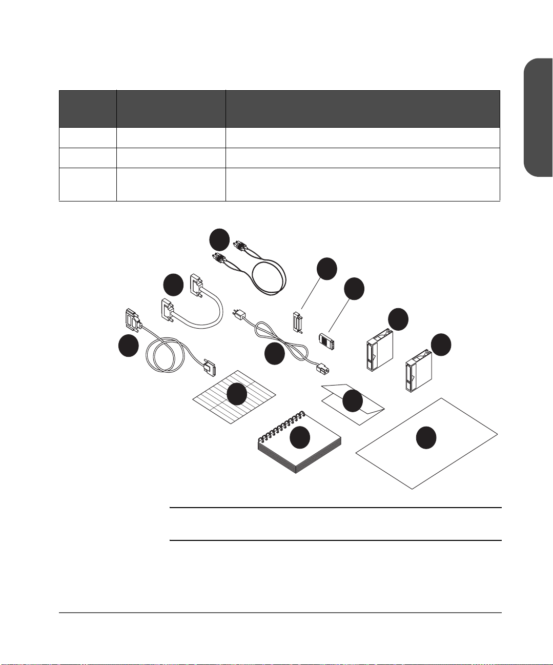
Table 1
10
12
11
Callout
Number
11 Regulatory Insert Contains safety and regulatory information.
12 Quick setup poster Overview of installation and configuration procedures.
Accessories
Component Description
Chapter 1
N/A Miscellaneous
information
Figure 1 Accessories
2
1
May include data sheets, upgrade information, product
information, and additional promotions.
3
6
7
8
5
4
10
11
12
9
Note Your cables may look different from those in Figure 1. Cable
types vary depending on library model.
Chapter 1 Identifying Product Components 13
Page 16

Choosing a Location
Choose a location that meets the criteria listed in Table 2. For additional
specifications, refer to Technical Specifications on page 181.
Table 2 Location Criteria
Room temperature 10-35º C (50-95º F)
Power source
LAN connection Locate the library near a LAN connection for connecting the RMC (remote
Library power
consumption
Air quality Minimal sources of particulate contamination. Avoid areas near frequently used
Humidity 20-80% RH
■ AC power voltage: 100-127 V or 200-240 V
■ Line frequency: 50-60 Hz
■ A dedicated circuit is required.
Caution: The AC power cord is the library’s main AC disconnect device and
must be easily accessible at all times.
management card).
2/20 series
4/40 series
6/60 series
8/80 series
10/100 series
doors and walkways, stacks of supplies that collect dust, and smoke-filled rooms.
Caution: Excessive dust and debris can damage tapes and tape drives.
Max: 200W
Max: 375W
Max: 560W
Max: 725W
Max: 1,200W
14 Choosing a Location Chapter 1
Page 17

Table 2
Location Criteria
Clearance 2/20, 4/40, and 6/60 series stand-alone configurations — located on or
below a table:
Back: 56 cm (22 in) for cooling and service.
Front: 86 cm (34 in) for operator access.
Sides: 56 cm (22 in) for removal of the external cover.
2/20, 4/40, and 6/60 series rackmounted configurations:
Back: 61 cm (24 in) minimum to allow adequate room for service
access.
Front: 86 cm (34 in) for operator access.
Sides: 56 cm (22 in) minimum
Height: For ease of use and optimum safety, the top of the library
should be mounted approximately 120 cm (48 in) above the
floor.
8/80 and 10/100 series tape libraries
Back: 56 cm (22 in) minimum
Front: 191 cm (75 in) minimum
Chapter 1
Sides: 5 cm (2 in) minimum
Floor rating For 8/80 and 10/100 series tape libraries only.
A fully loaded library can weigh up to 325 kg (715 lbs). Each caster supports
up to 96 kg (213 lbs). To support the weight exerted on the floor by the casters,
the floor rating must meet or exceed 1,694 kg per square meter (347 lbs per
square foot).
Tip rating For 8/80 and 10/100 series libraries only.
Do not tip the library more than 10°. Ensure that the location for the library has
a level surface.
Chapter 1 Choosing a Location 15
Page 18

Table 2
Location Criteria
Rack location
requirements
For 8/80 and 10/100 series libraries only.
Refer to the Rack Systems User’s Manual (included with the accessory kit or
available at http://www.hp.com/racksolutions
) for more information on
installing the rack. This information includes: using the anti-tip mechanism,
securing the rack to the floor, and weight/space requirements.
16 Choosing a Location Chapter 1
Page 19

Installing the 2/20, 4/40 & 6/60 Series Libraries into a Rack
The instructions in this section apply to 2/20, 4/40, and 6/60 series libraries
mounted in a standard 19-inch rack with a depth between 24 and 34 inches.
Caution Make sure that the rack and all equipment mounted in the rack
have a reliable ground connection.
Verify that the total current of the rack components does not
exceed the current rating of the power distribution unit or outlet
receptacles.
WARNING Do not move the library without additional help or an
appropriately rated lift device. The 2/20 series library weighs
40 kg (87 lb). The 4/40 series library weighs 75 kg (165 lb).
The 6/60 series library weighs 104 kg (249 lb).
Tools and Parts
Before you begin, ensure that you have the following:
■ Phillips #2 screwdriver
■ Torx screwdriver with T20 and T25 bits
Chapter 1
■ 1/2-inch open-end wrench
Chapter 1 Installing the 2/20, 4/40 & 6/60 Series Libraries into a Rack 17
Page 20
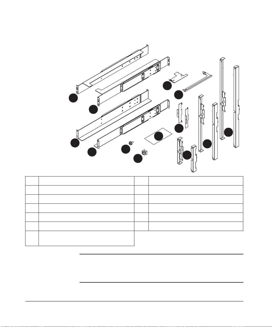
Figure 2 Rack Kit Parts
10
11
12
13
9
1
10
2
8
13
7
3
4
1 Upper left rail (1) 8 Flush-mount trim brackets (2)
2 Upper right rail (1) 9 2/20 series stop bracket (1)
3 Lower left rail (1) 10 4/40 and 6/60 series stop bracket (1)
4 Lower right rail (1) 11 2/20 series trim brackets (2)
5 10-32 Screws (20) 12 4/40 series trim brackets (2)
6 10-32 Clip nuts (20) 13 6/60 series trim brackets (2)
7 Clip nut template
(3 packaged together, one per model)
5
6
11
12
Note The rack kit includes extra trim brackets. The smaller flush-mount
trim brackets are used with flush-mount racks. The larger trim
brackets are typically used with older HP racks that have a
55mm bezel depth.
18 Installing the 2/20, 4/40 & 6/60 Series Libraries into a Rack Chapter 1
Page 21

Rackmounting the Library
WARNING Before you begin, lower the rack’s leveler feet with the open-
Note For easiest access to the display panel and to the tape drawers,
1. Use the template for your model library as a guide, and install five clip
nuts into each front column of the rack (Figure 3 on page 20, Figure 4 on
page 20, or Figure 5 on page 21, depending on your library model). The
upper grey clip nuts (item “a” below) are used for older HP racks (55-mm
bezel depth). The lower grey clip nuts (item “b” below) are used for flushmount racks.
ended wrench, and extend the rack’s anti-tip foot. Failure to
extend the anti-tip foot could result in personal injury or damage
to the tape library if the rack tips over.
mount the top of the library in the middle of the rack or 120 cm
(48 in) above the floor.
#
#
a
b
#
#
#
#
#
#
#
#
Chapter 1
Use the template as a guide, and install four clip nuts into each back
column of the rack.
Note Use the EIA markers as a reference point to ensure that the holes
on the rack correspond to the holes on the template. The EIA
markers on the template are represented by #>. Your rack might
look different from the illustration. If the holes in the rack do not
align with the template, move the template up one or two holes
to create proper alignment.
Chapter 1 Installing the 2/20, 4/40 & 6/60 Series Libraries into a Rack 19
Page 22
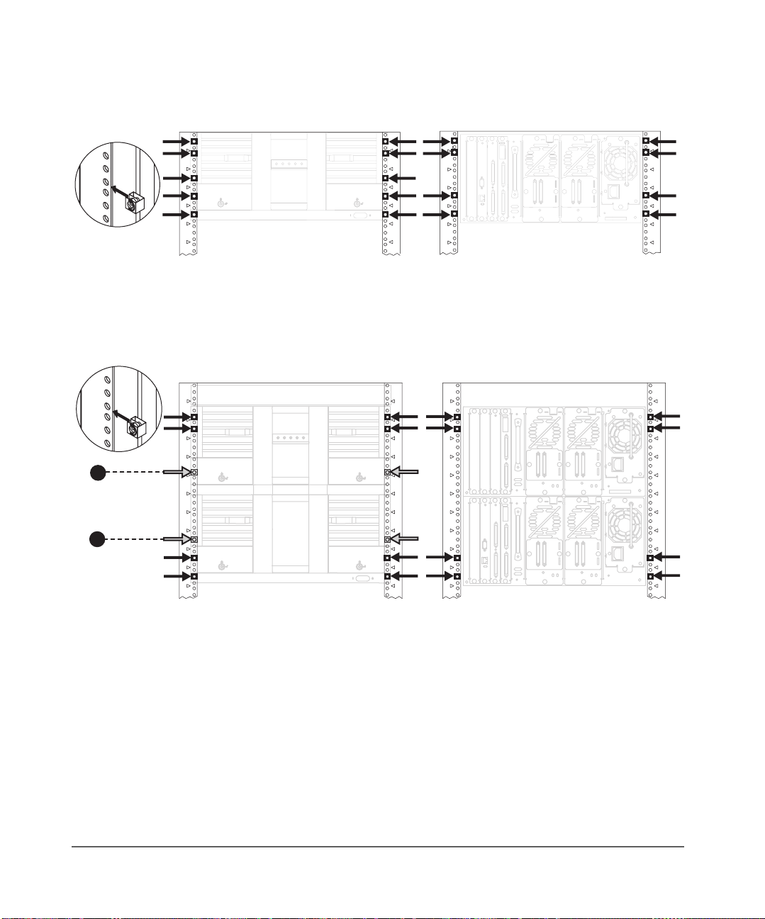
Figure 3 Clip Nut Placement (2/20 Series)
#
#
#
#
#
#
#
#
#
#
#
#
Front Back
Figure 4 Clip Nut Placement (4/40 Series)
#
#
#
#
a
b
#
#
#
#
#
#
# #
# # #
#
#
#
#
#
#
#
#
#
#
#
#
#
#
#
#
#
#
#
#
#
#
#
#
#
#
#
#
#
#
#
#
#
#
#
#
#
#
#
#
#
Front
Back
20 Installing the 2/20, 4/40 & 6/60 Series Libraries into a Rack Chapter 1
Page 23
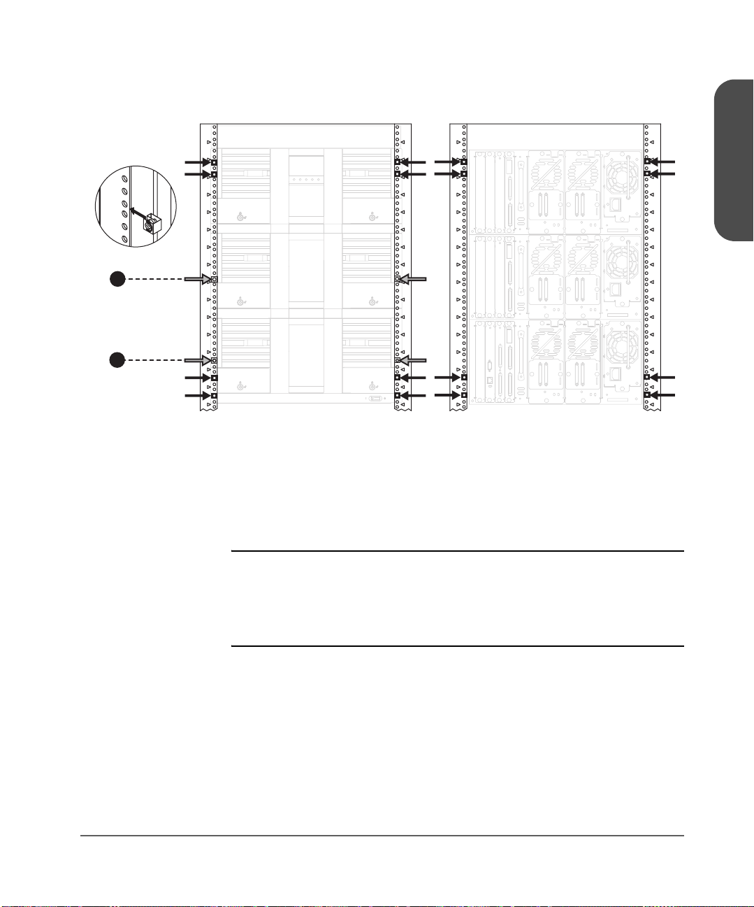
Figure 5 Clip Nut Placement (6/60 Series)
#
#
#
#
#
#
#
#
a
b
#
#
#
#
#
#
#
# #
##
##
##
##
#
#
#
#
#
#
#
#
#
#
#
#
Front Back
2. Align the upper (black) rail with the top two clip nuts and loosely install a
screw into each clip nut. Slide the rail out so that it equals the rack depth,
and attach to the back clip nuts. To allow for enough clearance, do not
tighten these screws until you have installed the library.
#
#
#
#
#
#
#
#
#
#
#
#
#
#
#
##
##
##
##
#
#
#
#
#
#
#
#
#
#
#
#
Chapter 1
Note Ensure that you are using the appropriate holes in the upper rail
to allow enough clearance, illustrated in Figure 6 on page 22.
The clearance between the top and bottom rails should be
approximately: 2/20 series = 22 cm (9 in); 4/40 series = 43 cm
(17 in); 6/60 series = 65 cm (26 in).
Chapter 1 Installing the 2/20, 4/40 & 6/60 Series Libraries into a Rack 21
Page 24
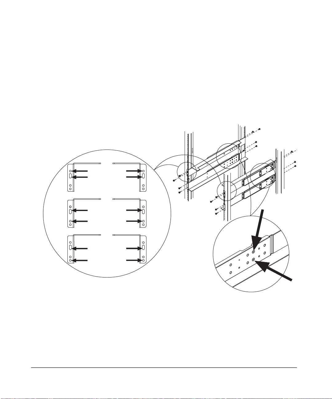
3. Align the lower (black/silver) rail with the lower two clip nuts, and loosely
install a screw into each clip nut. (See Figure 6.)
a. Slide the rail so that it equals the rack depth, and loosely install the
screws.
b. Tighten all screws to secure the rails.
c. Tighten the two pre-installed screws inside each mounting rail to
secure the rail in position.
Figure 6 Upper and Lower Rails
20
40
60
22 Installing the 2/20, 4/40 & 6/60 Series Libraries into a Rack Chapter 1
Page 25

4. Install the library.
WARNING The majority of the weight is near the back of the library. Use
Note To reduce the weight of the library, you can easily remove all the
2/20 Series Library:
With the help of another person, use the lifting straps built into the sides of
the library, and slide the library between the upper and lower sets of
mounting rails. Remove the lifting straps once the library is partially
installed. Save these straps for future use when moving the library.
Figure 7 Lifting Straps
Chapter 1
appropriate force when lifting the library, while ensuring the
library remains level to avoid overturning.
drives. See Removing and Replacing Drive Modules on
page 162 for more information.
Chapter 1 Installing the 2/20, 4/40 & 6/60 Series Libraries into a Rack 23
Page 26

4/40 and 6/60 Series Libraries:
Use a mechanical lift that is rated to the weight of the library, and follow
the steps below to install the library.
a. Break away the edges of the packing material at the bottom of the
library.
b. Use the straps to ease the library onto an appropriately rated
mechanical lift. Use the lift to raise the library so that it aligns with the
bottom rails.
c. Slide the library onto the lower rails. Have at least one person guide
the library from the front and one person pull the library from the
back, using the vertical handle (Figure 8 on page 24).
d. Remove the lifting straps once the library is partially installed. Save
the straps for future use when moving the library.
Figure 8 Library Installation
Caution Do not push the library from the front. Use the handle shown in
Figure 8. DO NOT pull on the handle(s) located on the back of
the power supply or drive modules.
24 Installing the 2/20, 4/40 & 6/60 Series Libraries into a Rack Chapter 1
Page 27

WARNING Do not move the library without additional help or an
appropriately rated lift device. The 2/20 series library weighs
40 kg (87 lb). The 4/40 series library weighs 75 kg (165 lb).
The 6/60 series library weighs 104 kg (249 lb).
5. Tighten the screws on the top mounting rail to secure the library.
6. Install the stop bracket to ensure the library is secured inside the rack, and
will not come out past the service position (approximately 2/3 of the
library is out of the rack).
2/20 Series Library:
a. From the back of the library, unscrew the power supply thumbscrew
by hand or with a screwdriver.
b. Install the stop bracket by sliding the edge of the bracket under the
thumbscrew and threading the tab through the latch stop.
c. Tighten the power supply thumbscrew to secure the bracket to the
library.
Figure 9 Installing the Stop Bracket for the 2/20 Series Library
Chapter 1
Chapter 1 Installing the 2/20, 4/40 & 6/60 Series Libraries into a Rack 25
Page 28

4/40 and 6/60 Series Libraries:
a. Ensure access to the top of the library. If necessary, push the library to
the service position to access the top cover. Do not push the library
past the latch stop tabs.
b. Remove the left back screw from the top cover.
c. Install the stop bracket by inserting the tab into the latch stop.
d. Re-install the screw into the top cover.
Figure 10 Installing the Stop Bracket for 4/40 and 6/60 Series Libraries
26 Installing the 2/20, 4/40 & 6/60 Series Libraries into a Rack Chapter 1
Page 29

7. Insert trim brackets into the slots on each side of the library (Figure 11
through Figure 13).
Figure 11 Trim Brackets (2/20 Series)
Chapter 1
(flush-mount trim brackets)(larger trim brackets)
Note The rack kit includes extra trim brackets. The smaller flush-mount
trim brackets are used with flush-mount racks. The larger trim
brackets are typically used with older HP racks that have a
55mm bezel depth.
Chapter 1 Installing the 2/20, 4/40 & 6/60 Series Libraries into a Rack 27
Page 30

Figure 12 Trim Brackets (4/40 Series)
(flush-mount trim brackets)(larger trim brackets)
Note The rack kit includes extra trim brackets. The smaller flush-mount
trim brackets are used with flush-mount racks. The larger trim
brackets are typically used with older HP racks that have a
55mm bezel depth.
28 Installing the 2/20, 4/40 & 6/60 Series Libraries into a Rack Chapter 1
Page 31

Figure 13 Trim Brackets (6/60 Series)
Chapter 1
(flush-mount trim brackets)(larger trim brackets)
Note The rack kit includes extra trim brackets. The smaller flush-mount
trim brackets are used with flush-mount racks. The larger trim
brackets are typically used with older HP racks that have a
55mm bezel depth.
Chapter 1 Installing the 2/20, 4/40 & 6/60 Series Libraries into a Rack 29
Page 32

8. Open the tape drawers and tighten the screws to secure the library into
place (Figure 14).
— For trim brackets, tighten the existing thumbscrews.
— For flushmount brackets, use two 10-32 x .50 screws.
Note The drawers may be key locked. The keys are attached to the
power supply handle on the back of the library.
Figure 14 Location of Securing Screws
(larger trim brackets)
30 Installing the 2/20, 4/40 & 6/60 Series Libraries into a Rack Chapter 1
(flush-mount trim brackets)
Page 33

Preparing the Host for Installation
Install the SCSI host bus adapter card(s) and compatible driver(s). Refer to the
host computer user manual and host bus adapter card instructions, and follow
these general procedures:
■ When the host is powered on, install software and/or driver(s) into the
host that are compatible with the library.
■ If the host computer is connected to a network, check with the system
administrator before turning off power.
■ Properly power off all peripheral devices connected to the host computer.
■ Power off the host.
■ Use proper procedures to prevent electrostatic discharge (ESD).
■ Make sure that the host computer has an appropriate number of card
expansion slots available for your library model.
■ Ensure the host bus adapter card is supported by your backup software
application.
■ For optimum performance, there should be a maximum of one tape drive
per bus. HP supports up to two drives per SCSI host bus adapter, but
recommends only one drive per bus. If compression is used when
attaching two drives per bus, keep in mind the combined transfer rate of
the drives and overhead of the bus must not exceed the throughput of the
host bus adapter used.
■ Refer to Appendix A and the ANSI SCSI cable specification for more
information on SCSI cable length requirements.
■ Check for available SCSI IDs if you are installing the library onto the same
SCSI bus as other devices. You might need to change the SCSI ID from the
library front panel display if you think there will be an ID conflict with
other devices.
Chapter 1
Note You can use HP Library & Tape Tools to identify available SCSI
IDs. See page 154 for installing and using this diagnostic utility.
Chapter 1 Preparing the Host for Installation 31
Page 34

Connecting and Powering on the Library
This section includes information and illustrations for the following:
■ Library back panel
■ SCSI cabling connections
■ Fibre Channel cabling connections
Note The figures in this section depict 2/20, 4/40, 6/60, 8/80, and
10/100 series tape libraries. The number of drives and cards
will vary, depending on your model.
32 Connecting and Powering on the Library Chapter 1
Page 35

Library Back Panel
DRV
DRV
10
DRV
DRV
DRV
DRV
DRV
DRV
DRV
DRV
2/20
4/40
8/80
6/60
10/100
Figure 15 Library Back Panel Features
Chapter 1
1
1
1
1
1
1
1
1
6
DRV
DRV
9
10
7
10/100
5
4
DRV
DRV
7
8
7
8/80
5
4
5
DRV
6
7
6/60
DRV
5
4
3
1
DRV
4
DRV
2
7
7
4/40
2/20
DRV
5
4
2
DRV
3
4
1 Vacant slot 5 Slave controller card
2 Remote management card 6
3 Library controller card 7 Power supply (standard or redundant)
4 Fibre Channel controller (optional)
Chapter 1 Connecting and Powering on the Library 33
Library expansion card (For the 8/80 and
10/100 series tape libraries only)
Page 36

SCSI Cable Connections
Note Refer to Fibre Channel Cable Connections on page 41 if the
This section illustrates a standard SCSI configuration that produces a high level
of data storage performance (one SCSI host bus adapter card for each drive in
the library with the library controller daisy-chained to the first drive). HP
supports up to two drives per SCSI host bus adapter, but recommends only one
drive per bus. If compression is used when attaching two drives per bus, keep
in mind the combined transfer rate of the drives and the overhead of the bus
must not exceed the throughput of the host bus adapter used.
Note Dual port cards are available and will reduce slot usage in the
Connect the library as follows (refer to Figure 16 on page 36 through Figure
19 on page 39):
1. Properly power off all peripheral devices connected to the host computer.
2. Power off the host. If the host is connected to a network, check with the
system administrator before turning off power.
library is configured with Fibre Channel.
host system.
3. Connect a 68-pin jumper cable from the top connector of the library
controller to the left drive module on level 1 (drive module 1).
Caution Use SCSI cables and HVDS differential terminators for high-
voltage SCSI interfaces. Use SCSI cables and LVDS differential
terminators for low-voltage SCSI interfaces. The label on the
library controller indicates high or low voltage.
4. Connect the appropriate 68-pin SCSI terminator to the bottom connector
on the library’s controller card.
5. Connect a 68-pin SCSI cable from a host SCSI card to each drive module.
Add the appropriate terminators to the remaining SCSI connectors.
34 Connecting and Powering on the Library Chapter 1
Page 37

6. Connect a category 5 ethernet cable from the remote management card to
an active network port (see Using the Remote Management Card on
page 96).
Note The AC power cord is the library’s main AC disconnect device
and must be easily accessible at all times.
7. For 2/20, 4/40, and 6/60 Series Libraries:
— Connect a power cord to each power supply module on all levels.
For 8/80 and 10/100 Series Libraries:
— Connect the power cords on the rack to a power outlet on each
library level.
— Connect the power cord from the power distribution unit to a
dedicated, grounded power receptacle.
8. Power on the library. The power (standby) switch is recessed and on the
lowest level on the front of the library.
After the power-up test is complete (after several minutes), you will see the
Home Screen on the library's front panel. The Home Screen displays the
status of the drives and library. See Front Panel Overview on page 60.
9. Power on other peripherals, and then the host.
Chapter 1
Chapter 1 Connecting and Powering on the Library 35
Page 38

Figure 16 2/20 Series SCSI Cable Connections
1Host (user configured)
2 Remote management card LAN connection
3 Appropriate 68-pin SCSI terminator
4 Jumper cable with SCSI 68-pin connectors
5 SCSI cable from drive 1 to host
6 SCSI cable from drive 2 to host
36 Connecting and Powering on the Library Chapter 1
Page 39

Figure 17 4/40 Series SCS Cable Connections
7
8
LAN
Chapter 1
3
564321
1Host (user configured)
2 Remote management card LAN connection
3 Appropriate 68-pin SCSI terminator
4 Jumper cable with SCSI 68-pin connectors
5 SCSI cable from drive 1 to host
6 SCSI cable from drive 2 to host
7 SCSI cable from drive 3 to host
8 SCSI cable from drive 4 to host
Chapter 1 Connecting and Powering on the Library 37
Page 40

Figure 18 6/60 Series SCS Cable Connections
10
9
8
7
LAN
564321
1 Host (user configured) 6 SCSI cable from drive 2 to host
2 Remote management card LAN connection 7 SCSI cable from drive 3 to host
3 Appropriate 68-pin SCSI terminator 8 SCSI cable from drive 4 to host
4 Jumper cable with SCSI 68-pin connectors 9 SCSI cable from drive 5 to host
3
5 SCSI cable from drive 1 to host 10 SCSI cable from drive 6 to host
38 Connecting and Powering on the Library Chapter 1
Page 41

Figure 19 8/80 and 10/100 Series SCSI Cable Connections
DRV
DRV
DRV
DRV
DRV
DRV
DRV
DRV
DRV
10
LAN
11
12
13
14
10
DRV
Chapter 1
DRV
9
DRV
10
3
13
14
DRV
7
DRV
8
3
11
12
DRV
5
DRV
6
3
1
9
10
DRV
3
DRV
4
3
7
8
DRV
1
DRV
2
3
Chapter 1 Connecting and Powering on the Library 39
LAN
432
5 6
Page 42

Table 3 8/80 and 10/100 Series SCSI Cable Connections
1Host (user configured)
2 Remote management card LAN connection
3 Appropriate 68-pin SCSI terminator
4 SCSI cable from the library controller card to drive 1
5 Host SCSI cable to drive 1
6 Host SCSI cable to drive 2
7 Host SCSI cable to drive 3
8 Host SCSI cable to drive 4
9 Host SCSI cable to drive 5
10 Host SCSI cable to drive 6
11 Host SCSI cable to drive 7
12 Host SCSI cable to drive 8
13 Host SCSI cable to drive 9
14 Host SCSI cable to drive 10
40 Connecting and Powering on the Library Chapter 1
Page 43

Fibre Channel Cable Connections
There are several Fibre Channel cabling options. Figure 20 provides an
overview.
Note When using hubs or switches, consult the user documentation for
those products. For detailed information on HP supported
topologies, refer to the SAN Solution Installation Guide available
from http://www.hp.com/go/support.
Figure 20 Fibre Channel Cabling Alternatives
CABLING ALTERNATIVE #1:
Connecting the library
directly to a host
Host
CABLING ALTERNATIVE #2:
Connecting the library to
the host through a hub or
switch (more detailed
instructions are on the
following pages)
Host
Hub/Switch
Chapter 1
Library
Library
Host
CABLING ALTERNATIVE #3:
Connecting the library to
multiple hosts through a
hub or switch
Hub/Switch
Library
Host
Chapter 1 Connecting and Powering on the Library 41
Page 44

The following steps illustrate a Fibre Channel connection between the host,
hub or switch, and library. Refer to Figure 22 on page 45 through Figure 25
on page 48, and connect the library as follows:
1. Ensure that the library and host are inactive, and the library is
disconnected from the host.
2. Ensure that the required host software has been installed.
3. Power off the host, hub, or switch. If the host is connected to a network,
check with the system administrator before turning off power.
4. Install a host bus adapter into the host computer. Use proper procedures to
prevent electrostatic discharge (ESD). Use wrist-grounding straps and antistatic mats when removing internal components.
5. Connect the hardware.
a. On each level of the library, connect the supplied SCSI jumper cable
from bus 1 on each Fibre Channel controller to the left connector on
the left drive module.
b. On each level of the library, connect the supplied SCSI jumper cable
from bus 2 on each Fibre Channel controller to the left connector on
the right drive module.
c. Connect the supplied SCSI jumper cable from the top connector on the
library controller card to the right connector on the left drive module
(drive module 1) to daisy chain the library controller to the drive.
d. Terminate the bottom connector on the library controller card.
e. Connect the appropriate SCSI terminator to the remaining connectors
on the drive modules. Ensure that the interface type matches your
library.
42 Connecting and Powering on the Library Chapter 1
Page 45

f. Connect the Fibre Channel cable(s) to the host, hub, or switch. If
necessary, connect the Fibre Channel cable to the GBIC provided
before connecting to the host, hub, or switch.
Figure 21 Connecting Fibre Channel Cables to the GBIC
Caution The Fibre Channel printed circuit boards may contain a laser
system (GBIC or GLM module) that is classified as a “Class-I
Laser Product” under a U.S. Department of Health and Human
Services (DHHS) Radiation Performance standard according to
the Radiation Control for Health and Safety Act of 1968 and
EN60825-1(+A11) safety of laser products. The compliance
statement is located on the module.
Chapter 1
6. Power on the hub or switch (if present).
Note The AC power cord is the library’s main AC disconnect device
and must be easily accessible at all times.
Chapter 1 Connecting and Powering on the Library 43
Page 46

7. For 8/80 and 10/100 Series Libraries:
Connect the power cords on the rack to a power outlet on each library
level.
For 2/20, 4/40, and 6/60 series libraries, skip to the next step.
8. Connect the power cord(s) from the library to a grounded power
receptacle, and power on the library. The power (standby) switch is
recessed and on the lowest level of the library.
After the power-up test is complete (after several minutes), you will see the
Home Screen on the library’s front panel. The Home Screen displays the
status of the drives and library.
9. From the front panel, configure the library for Fibre Channel. See
Configuring the Library for Fibre Channel on page 102 for more
information.
10. Connect a category 5 ethernet cable from the remote management card to
an active network port (see Using the Remote Management Card on
page 96).
11. Power on the host.
44 Connecting and Powering on the Library Chapter 1
Page 47

Figure 22 2/20 Series Fibre Channel Connections
8
LAN
Chapter 1
4
21
1 Hosts (user configured) 5 SCSI cable from the library controller card to drive 1
2 Hub or switch 6 SCSI cable from bus 1 on the Fibre Channel controller
to drive 1
3 Remote management card LAN
connection
4 Appropriate SCSI terminator 8 Fibre Channel cable to hub or switch
7 SCSI cable from bus 2 on the Fibre Channel controller
to drive 2
5
43
76
Chapter 1 Connecting and Powering on the Library 45
Page 48

Figure 23 4/40 Series Fibre Channel Connections
8
10
9
LAN
4
21
1 Hosts (user configured) 6 SCSI cable from bus 1 on the Fibre Channel
controller to drive 1
2 Hub or switch 7 SCSI cable from bus 2 on the Fibre Channel
controller to drive 2
3 Remote management card LAN
connection
4 Appropriate SCSI terminator 9 SCSI cable from bus 2 on the Fibre Channel
5 SCSI cable from the library
controller card to drive 1
46 Connecting and Powering on the Library Chapter 1
8 SCSI cable from bus 1 on the Fibre Channel
controller to drive 3
controller to drive 4
10 Fibre Channel cable to hub or switch
543
76
Page 49

Figure 24 6/60 Series Fibre Channel Connections
10
12
11
8
12
9
LAN
Chapter 1
4
4
21
543
76
1 Hosts (user configured) 7 SCSI cable from bus 2 on the Fibre Channel
controller to drive 2
2 Hub or switch 8 SCSI cable from bus 1 on the Fibre Channel
controller to drive 3
3 Remote management card LAN
connection
9 SCSI cable from bus 2 on the Fibre Channel
controller to drive 4
4 Appropriate SCSI terminator 10 SCSI cable from bus 1 on the Fibre Channel
controller to drive 5
5 SCSI cable from the library controller
card to drive 1
6 SCSI cable from bus 1 on the Fibre
11 SCSI cable from bus 2 on the Fibre Channel
controller to drive 6
12 Fibre Channel cable to hub or switch
Channel controller to drive 1
Chapter 1 Connecting and Powering on the Library 47
Page 50
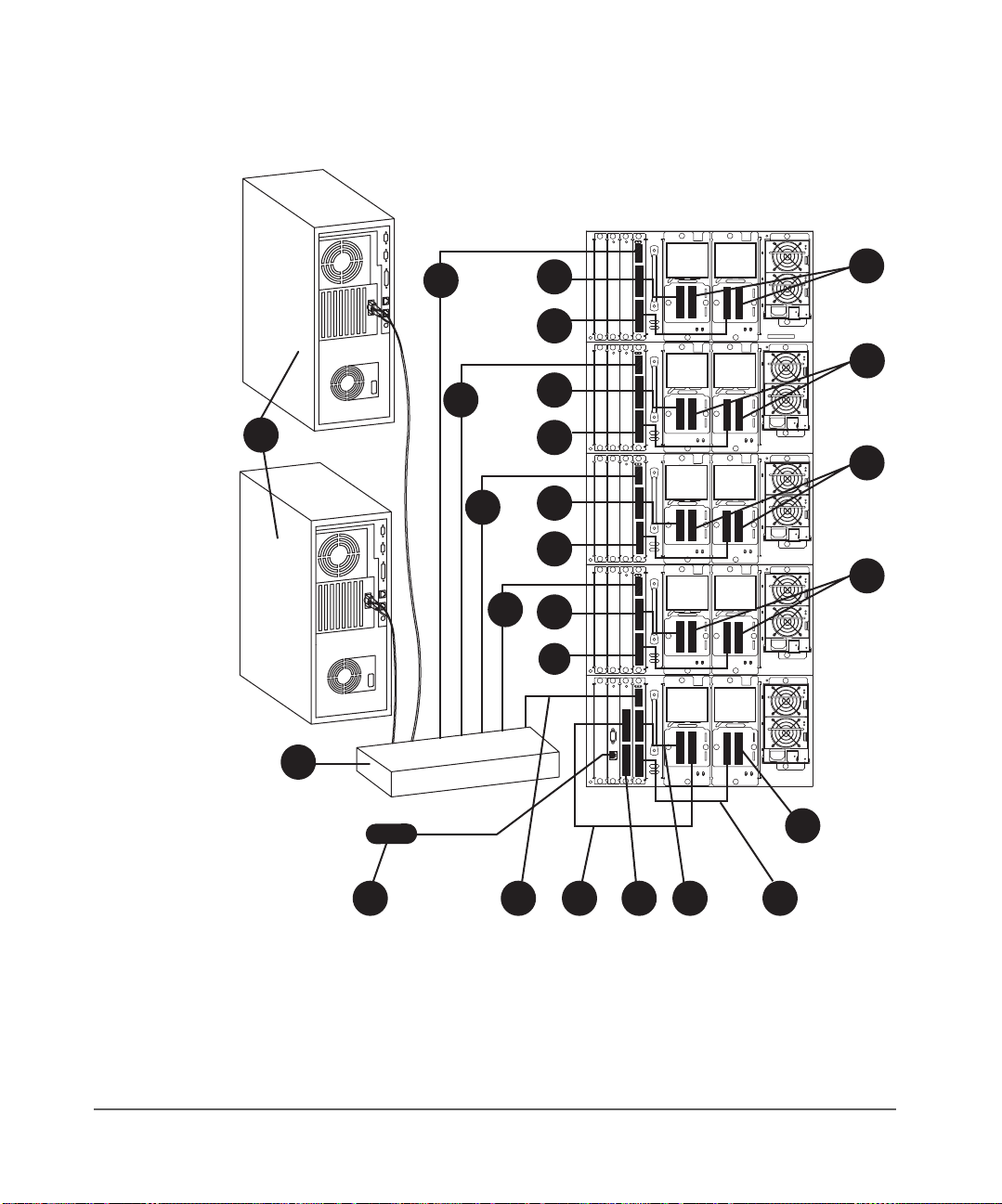
Figure 25 8/80 and 10/100 Series Fibre Channel Connections
DRV
4
15
9
16
DRV
4
13
7
DRV
10
DRV
8
6
6
1
4
14
11
DRV
5
DRV
6
6
12
DRV
DRV
3
4
9
4
6
10
DRV
DRV
1
2
2
LAN
6
374856
48 Connecting and Powering on the Library Chapter 1
Page 51

Table 4 8/80 and 10/100 Series Fibre Channel Connections
1Host (user configured)
2Hub or switch
3 Remote management card LAN connection
4Fibre Channel cable
5 SCSI cable from library controller to drive 1
6 Appropriate SCSI terminator
7 SCSI cable from bus 1 on the Fibre Channel interface to drive 1
8 SCSI cable from bus 2 on the Fibre Channel interface to drive 2
9 SCSI cable from bus 1 on the Fibre Channel interface to drive 3
10 SCSI cable from bus 2 on the Fibre Channel interface to drive 4
11 SCSI cable from bus 1 on the Fibre Channel interface to drive 5
12 SCSI cable from bus 2 on the Fibre Channel interface to drive 6
13 SCSI cable from bus 1 on the Fibre Channel interface to drive 7
14 SCSI cable from bus 2 on the Fibre Channel interface to drive 8
Chapter 1
15 SCSI cable from bus 1 on the Fibre Channel interface to drive 9
16 SCSI cable from bus 2 on the Fibre Channel interface to drive 10
Chapter 1 Connecting and Powering on the Library 49
Page 52

Verifying the Host Configuration
Once the library is connected to a host, the operating system must be
configured to recognize it (if it has not already been configured). The
procedures are different, depending on the host system:
■ Windows NT on page 51
■ Windows 2000 on page 51
■ Sun Solaris on page 52
■ HP-UX and MPE/iX on page 52
Backup Software Compatibility
Consult your software documentation for more information on installing,
configuring, and operating your backup software.
For software compatibility information, visit http://www.hp.com/go/
automated or the Website for the backup software manufacturer:
■ HP Omniback II™ (http://www.openview.hp.com/products/omniback)
■ Veritas Backup Exec™ (http://www.veritas.com)
■ Veritas NetBackup™ (http://www.veritas.com)
■ Computer Associates ARCserve 2000™ (http://www.ca.com/arcserve)
■ Legato Networker™ (http://www.legato.com)
■ Tivoli Storage Manager™ (http://www.tivoli.com)
Using HP Library & Tape Tools
In addition to the following procedures, you can also check the installation with
HP Library & Tape Tools available from http://www.hp.com/support/
TapeTools. See HP Library & Tape Tools on page 154 for more information.
With HP Library & Tape Tools installed on your host computer, you can do the
following and much more:
■ Identify all SCSI and Fibre Channel devices connected to your system
■ View detailed configuration, identification, inventory, and drive
information for the library
50 Verifying the Host Configuration Chapter 1
Page 53

Windows NT
Windows 2000
For Windows NT™ operating systems, perform the following operating system
configurations:
■ Install the appropriate host bus adapter(s)
■ Install the corresponding drivers for the interface card(s)
■ To verify the hardware installation, look for the library and drives after
powering up the host. Go into Settings -> Control Panel -> SCSI Adapter.
■ Install the backup software
■ Run a test backup to ensure that all components are properly configured.
For Windows 2000™ operating systems, perform the following operating
system configurations:
■ Install the appropriate host bus adapter(s)
■ Install the corresponding drivers for the interface card(s)
■ To verify the hardware installation, look for the library and drives after
powering up the host:
— Right click on My Computer
— Select Manage -> System Tools -> Device Manager
Chapter 1
— Medium Changer and Tape Drives should be listed
■ Install the backup software
■ Run a test backup to ensure that all components are properly configured.
Chapter 1 Verifying the Host Configuration 51
Page 54

Sun Solaris
HP-UX and MPE/iX
For Sun Solaris™ operating systems, perform the following operating system
configurations:
■ Install the appropriate host bus adapter(s)
■ Install the corresponding drivers for the interface card(s)
■ To verify the hardware installation, look for the library and drives after
powering up the host.
— Close all open applications and exit the Common Desktop
Environment (CDE).
— Type “init 0” at any prompt. This will shut down all processes, and
take you to the OpenBoot PROM.
— Type “reset”.
— At the OK prompt, type “probe-scsi-all”.
■ Install the backup software
■ Run a test backup to ensure that all components are properly configured.
For more information on configuring these operating systems and verifying the
connection, see the online configuration and diagnostic guide at http://
www.hp.com/go/support. Select your product and then select [manuals].
52 Verifying the Host Configuration Chapter 1
Page 55

Getting Started
Chapter 1
After you install and configure the library, you must complete the following
setup tasks from the library’s front panel:
■ Setting the date and time: When you first set up the library or if it has
been unplugged for an extended period of time (around 8 days), set the
library’s real-time clock. See Setting the Date and Time on page 108 for
more information.
■ Setting the mailslot configuration: The default setting is for a one-slot
mailslot. You can select a 0-slot, 1-slot, 1-magazine, or 2-magazine
mailslot. See Configuring the Mailslot on page 93 for more information.
Note Mailslot configuration must be set prior to installing the backup
software.
■ Configuring the library for web monitoring: You can monitor and
manage your library anywhere on the network through user friendly web
pages. See Using the Remote Management Card on page 96 for more
information.
■ Enabling the password: The library does not have an administrator
password enabled when it arrives. To ensure security and to get full use of
the remote management card, enable and select a password. Be sure to
remember this password. See Enabling and Changing the Password on
page 92 for more information.
Note You must first set a library password through the front panel to
configure the library using the remote management card (see
Enabling and Changing the Password on page 92).
Chapter 1 Getting Started 53
Page 56

Moving or Shipping the Library
WARNING Do not move the library without additional help or an
appropriately rated lift device. The 2/20 series library weighs
40 kg (87 lb). The 4/40 series library weighs 75 kg (165 lb).
The 6/60 series library weighs 104 kg (249 lb). The 8/80 and
10/100 series libraries weigh approximately 227 kg (500 lb).
Caution To avoid damage to the library, ensure that it is in an upright
position at all times. Never place the library on its sides.
Note During normal operation, changes to configurations are stored
in Non-Volatile (NV) RAM for eight days. All configuration
settings can be permanently saved to flash memory by power
cycling the library. This allows the settings to be recovered if the
library is unplugged for more than eight days. If this step is not
completed and the library is unplugged for more than eight
days, any new settings may be lost. Before shipping the library,
verify that the configuration settings were saved permanently by
first powering down the library, and then powering back up to
store the settings and to view them.
To move or ship the library:
1. Verify that all drives are empty. If a drive contains a tape, unload it. Refer
to the backup software documentation, use the remote management card
(see page 96), or use the front panel menu as follows:
a. From the Drive and Tape Operations menu, select Unload Tape from
Drive.
b. Use the [-] or [+] keys to select the drive you want to unload.
c. Select [Unload] to move the tape from the drive to the tape’s original
location (the slot it occupied before being loaded into the drive). If
that slot is occupied, you will be asked to select another slot location.
54 Moving or Shipping the Library Chapter 1
Page 57

The tape automatically rewinds before it is unloaded. A status screen
displays the library’s progress as the tape is relocated.
d. From the Drive and Tape Operations menu, select [Back] to return to
the Operations menu.
2. If shipping the library, remove tape cartridges from the magazines:
a. From the Magazine Access menu, select one of the following options:
—Unlock Door
—Unlock All Doors
Use the [-] and [+] keys to change the door selection.
b. Pull the unlocked drawer(s) out to access magazines and tapes. The
drawer may also be physically locked with a key. The key is typically
attached to the back of the power supply.
c. Remove the magazine by lifting it straight up with the handle.
d. To remove a tape, set the magazine on its back and grasp the top and
bottom corners of the tape. Pull the tape straight out of the magazine
and return the magazine to the library.
3. If shipping the library, lock the transport:
a. From the Administration menu, select the Run Test menu.
b. From Run Test, use the [-] or [+] keys to select Lock Transport.
c. Select [OK].
Chapter 1
d. Select [Run]. The front panel display will indicate that the transport
has been locked.
Caution Do not power off the library until the interface is inactive.
Removing power from a SCSI or Fibre Channel peripheral when
the bus is active can result in data loss and/or indeterminate bus
states.
4. Power off the library. The power “standby” switch is recessed to avoid
accidental power cycles.
Chapter 1 Moving or Shipping the Library 55
Page 58

5. To ship the library, remove all external cords, cables, and terminators. For
an internal move, only disconnect the power cables, SCSI cables, the RMC
ethernet cable, and the Fibre Channel connection from the host, hub, or
switch.
Note You do not need to remove the SCSI cables that connect the
controller or the Fibre Channel controller to the drive modules,
unless the library is being shipped.
WARNING Before moving the library, the leveler feet must be fully raised to
allow for ground clearance. Once the library is in place, the
leveler feet should be fully lowered. Failure to follow these
precautions could result in personal injury or damage to the
library.
6. When moving a stand-alone library, raise the library’s leveler feet (for the
6/60 series library only) before moving it to its new location. Reconnect
the library using the procedures in Connecting and Powering on the
Library on page 32.
7. For shipping, place the library in the original packing materials.
For 8/80 and 10/100 Series Libraries:
Refer to the Rack System User Manual for more information on
repackaging the library. The manual is available at http://www.hp.com/
racksolutions.
Secure library components for shipping by doing the following:
— Remove the filler panels from the rack
— Wrap the filler panels with bubble-wrap
— Secure the outer rack side panels to the rack with shrink-wrap or
bands
Note If you no longer have the original packaging, contact your sales
or service representative to obtain packaging materials.
— For libraries mounted in a rack, proceed to the next step.
56 Moving or Shipping the Library Chapter 1
Page 59

8. Extend the rack’s anti-tip foot.
WARNING Failure to extend the anti-tip foot could result in personal injury
or damage to the library.
9. Open the magazine drawers and loosen the screws that lock the library
into place (Figure 14 on page 30). The screws are located in front of the
trim brackets.
10. Remove the stop bracket. (See Figure 9 on page 25 and Figure 10 on
page 26.)
11. Push the library out of the rack until it hits the latch stops (approximately
2/3 of the library is out of the rack).
12. Reattach the lifting straps to the sides of the library.
13. Release the library from the rack.
4/40 and 6/60 Series Libraries:
Depress the latch stops at the top of the library with a screwdriver or
similar tool (Figure 26 on page 58).
2/20 Series Libraries:
If the library does not have enough clearance above for a tool to be
inserted, unscrew the four screws (two on each side) from the top (black)
mounting rail on the front of the library. Pull the library partially out, then
lower the front half of the library to ease it under the latch stops.
Chapter 1
WARNING Once you have loosened the mounting screws, the library is no
longer secured inside the rack and can cause bodily harm and/
or damage to the library if it is dropped.
Chapter 1 Moving or Shipping the Library 57
Page 60

Figure 26 Latch Stops
14. Remove the library from the rack.
2/20 Series Libraries:
With the help of two people or a lift, slide the library out of the rack and
place it in the original packaging materials.
4/40 and 6/60 Series Libraries
a. Position the original shipping pallet in front of the rack.
b. With at least one person on each side, slide the library out of the rack
and onto an appropriately rated mechanical lift. Lower the library
onto the shipping pallet.
WARNING Do not move the library without additional help or an
appropriately rated lift device. The 2/20 series library weighs
40 kg (87 lb). The 4/40 series library weighs 75 kg (165 lb).
The 6/60 series library weighs 104 kg (249 lb).
Note If you no longer have the original packaging, contact your sales
or service representative to obtain packaging materials.
58 Moving or Shipping the Library Chapter 1
Page 61

Operating the Library
Chapter Overview
This chapter describes the following:
■ Front Panel Overview on page 60
■ Understanding the Menu Structure on page 64
■ Using Tapes on page 65
■ Accessing Tapes in the Library on page 81
■ Drive and Tape Operations on page 86
2
Chapter Overview 59
Page 62

Front Panel Overview
The front panel displays icons and text that provide library, drive, and tape
status information. It also uses text prompts and warnings to guide you while
making changes. Use the button immediately below the label to execute the
desired function. The function of the buttons varies between screens.
The display defaults to the Home Screen. Figure 27 on page 60 shows a
typical Home Screen view, using a four-drive model as an example.
Figure 27 Home Screen
The Home Screen shows the following:
■ Statement indicating the general condition of the library
■ Drive and tape status
■ Tape bar code (if applicable)
■ [Main] option to go to the Information, Operations, and Administration
menus
■ [Icon] option to display the icons with a description
■ An icon that indicates the general status of the library. This icon may
display a reverse video reminder (icon background reverses to black)
when there has been a change in the status of the library. Select this key to
obtain more information about the library.
■ [Mail] option to access the mailslot
■ [Map] option to view information about the drive and tape slots
60 Front Panel Overview Chapter 2
Page 63

Status Bar
All screens, except the Home and Map screens, show a status bar that
summarizes library and drive status (Figure 28 on page 61).
The status bar shows a reverse video reminder (icon background reverses to
black) for drive or library errors that have been entered in the media log or
hard error log. You may clear this reminder by viewing either the
Library Hard Error Log screens.
The library’s reverse video reminder will also be set if the library’s partial
availability status changes (see Partial Availability State on page 120). You
can clear this reminder by viewing the
center icon button on the Home screen.
Figure 28 Status Bar from Main Menu Screen
Chapter 2
Drive Log or
Library Status screen by selecting the
Chapter 2 Front Panel Overview 61
Page 64

The status bar can display the icons listed in Table 5 on page 62 and Table 6
on page 62.
Table 5 Drive Icons
Power is off Online
Failed, offline Full and idle
Needs to be cleaned Unloading a tape
Offline Seeking data on a tape
Failed, online Writing data to a tape
Tape is cleaning a drive Rewinding a tape
Tape is write protected Reading a tape
Empty Erasing a tape
Loading a tape
Table 6 Library Icons
Failed Partially
Healthy
available
62 Front Panel Overview Chapter 2
Page 65

Nesting
Each level of password-protected menus (Administration and Service) includes
all options available in the subordinate menu. For example, all options
available in the
functionality reduces the need to return to the
password. Figure 29 illustrates this “nesting” concept.
Figure 29 Nesting
Information Operations Administration Service
Chapter 2
Administration Menu are also included in the Service Menu. This
Main Menu or re-enter a
Library Information
Drive Information
View Configuration
Date and Time
Firmware Revisions
Power Supplies
Drive and Tape
Operations
Magazine Access
Mailslot Access
Information
Operations
Change
Configuration
Run Test
Online Drive Repair
Set Date and Time
Upgrade Drive
Firmware
Information
Operations
Change
Configuration
Run Test (with
additional capability)
Online Drive Repair
Set Date and Time
Upgrade Drive
Firmware
Note The front panel defaults back to the home or logo screen after
approximately three minutes of inactivity, unless an error
message or confirmation message is displayed that needs to be
acknowledged.
Chapter 2 Front Panel Overview 63
Page 66

Understanding the Menu Structure
Figure 30 Front Panel Menu Structure
64 Understanding the Menu Structure Chapter 2
Page 67

Using Tapes
Chapter 2
This section includes information on:
■ Mixed Media on page 66
■ Media Migration on page 67
■ Using HP Ultrium Cartridges on page 69
■ Using DLT Tape Cartridges on page 74
Caution It is critical to ensure that the media you use matches the format
of your tape drive. Cleaning cartridges and formatted data
cartridges are unique for each drive technology. Damage may
occur if inappropriate media is used in tape drives.
Chapter 2 Using Tapes 65
Page 68

Mixed Media
Mixed media refers to the option to backup to more than one drive type, such
as DLT and LTO, within the same physical tape library.
General considerations when using mixed media:
■ Some backup software packages do not support mixed media. Consult
your software provider to verify that your configuration is supported.
■ In order to provide full mailslot support in a mixed media library, one
magazine is required for each drive type for a possible total of 10
mailslots, depending on library model.
■ Only DLT tapes can be used in a DLT magazine, and only Ultrium tapes
can be used in an Ultrium magazine.
■ When mixing drive types, HP only supports using the same type of drive
per level of the library.
■ HP Library & Tape Tools version 2.2 or greater is required for diagnostic
support.
■ Upgrade kits are available from HP for Ultrium tape drives, magazines,
and tape cartridges.
66 Using Tapes Chapter 2
Page 69

Media Migration
Utilities and services are available to assist you in migrating from one drive
technology to another.
HP Library & Tape Tools
The HP Library & Tape Tools diagnostic assists you in installing and supporting
your tape library. This tool provides an intuitive graphical user interface with
integrated context-sensitive help. It can be downloaded free of charge from
http://www.hp.com/support/tapetools
Among the many features is a Migrate Backup Media option available from the
Utility menu. This utility will copy data from DLT drives to DLT or Ultrium drives.
See Figure 31 for a screen shot from HP Library & Tape Tools.
Figure 31 HP L&TT Media Migration Utility
Chapter 2
.
Note Before using the media migration utility in HP Library & Tape
Tools, ensure that the source media is write-protected. This utility
does not provide any library control. You must load media into
the selected drives using the library or autoloader front panel,
Web-Based Library Administrator, or your backup software
utility.
Chapter 2 Using Tapes 67
Page 70

For more information on using HP Library & Tape Tools for media migration,
refer to http://www.hp.com/support/tapetools
.
Service Provider
Vogon International provides migration, recovery, and forensic services with
offices in the United Kingdom, Germany, and the United States. Vogon offers a
standard service and a fast-track service that generally has a 50% quicker
turnaround time from the standard service. Prices vary, depending on the
complexity of the service requested.
Vogon International Ltd.
Web address: http://www.vogon-international.com
Mailing address: Talisman Business Centre
Talisman Road
Bicester, Oxfordshire
OX6 OJX
Telephone: United States: (405) 321 2585
UK: 44 (0) 1869 355255
Germany: 49 (0) 89 3235030
68 Using Tapes Chapter 2
Page 71

Using HP Ultrium Cartridges
In addition to the information provided in this manual, refer to the
documentation provided with your media for more information.
Caution HP Ultrium tape drives require special cleaning cartridges and
A unique feature of Ultrium tape cartridges is LTO-Cartridge Memory (LTOCM). LTO-CM is an intelligent memory chip embedded into the cartridge. It
uses a radio frequency interface that eliminates the need for a physical power
or signal connection between the cartridge and drive. Information normally
stored in the header at the beginning of the tape is contained in the LTO-CM,
including identification and usage information such as the number of times the
cartridge has been loaded, when it was last cleaned, and error logs.
In addition to the information provided in this manual, you may also want to
refer to the documentation provided with your Ultrium media.
Maintaining Ultrium Cartridges
Make it a practice to visually inspect your tape cartridges when loading or
removing them from your tape library. Taking a few minutes to check the
condition of your cartridges will lower the risk of repeated failures and help
ensure uninterrupted backup.
Do not apply more than one label onto Ultrium cartridges, as extra labels can
cause the cartridges to jam in the tape drive.
Chapter 2
data cartridges formatted specifically for HP Ultrium. To avoid
damage to your tape drive, it is critical to use appropriate
cleaning cartridges and properly formatted data cartridges.
Caution Do not bulk erase Ultrium formatted cartridges. This will destroy
pre-recorded servo information and make the cartridges
unusable.
Chapter 2 Using Tapes 69
Page 72

Write-Protecting Ultrium Cartridges
Each cartridge has a sliding write-protect switch. Using the write-protect switch
ensures data safety for files that have been previously written to tape,
preventing additional files from being written to that tape.
To change the write-protect setting, slide the red tab on the base of the
cartridge (Figure 32):
■ Right to prevent data from being written to the cartridge. The red tab on
the cartridge displays a padlock when the write-protect switch is in the
“ON” position.
■ Left to allow data to be written to the cartridge (unless the tape is write-
protected electronically through your backup software). The padlock on
the red tab cannot be seen and the hole is exposed when the write-protect
switch is in the “OFF” position.
With the write-protect switch in either position, data can be read from the
cartridge.
Figure 32 Ultrium Write-Protect Switch Settings
70 Using Tapes Chapter 2
Page 73

Using Ultrium Cartridge Bar Code Labels
Make it a practice to use barcode labels on your tape cartridges. Your host
software may need to keep track of the following information and the
associated bar code:
■ Date of format or initialization
■ Cartridge owner (such as a group or department)
■ Storage purpose
Note If the host software does not keep track of this information,
create a method for doing so.
Ultrium cartridges have a recessed area located on the face of the cartridge
next to the write-protect switch. Use this area for attaching the bar code label
(Figure 33 on page 71). Do not apply labels onto the cartridge except in this
designated area.
Caution The bar code label should be applied as shown in Figure 33 on
page 71 with the alphanumeric portion facing the hub side of
the tape cartridge. Never apply multiple labels onto a cartridge,
as extra labels can cause the cartridge to jam in a tape drive.
Chapter 2
Figure 33 Proper Ultrium Label Position
Chapter 2 Using Tapes 71
Page 74

Ordering Ultrium Cartridges and Bar Code Labels
Ultrium Tape
HP Ultrium tape cartridges can be purchased in a variety of ways.
Cartridges
Note Outside of North America, contact your nearest HP authorized
dealer or sales representative.
■ Call 1-800-752-0900 (North America only) for the location of the nearest
authorized Hewlett-Packard dealer
■ Contact HP Direct:
— 1-800-538-8787 (North America only)
—HP Direct
Hewlett-Packard
ATTN: Mail Order
P.O . B ox 1 14 5
Roseville, CA 95678
■ Visit the HP Business Store at http://www.bstore.hp.com (where available)
Table 7 lists HP Ultrium tape cartridges and their part numbers.
Table 7 Ultrium Tape Cartridges
Part Number Description
Data Cartridges
C7970A 100 GB
C7971A 200 GB
Cleaning Cartridges
C7978A HP Ultrium Universal Cleaning Cartridge
72 Using Tapes Chapter 2
Page 75

Ultrium Bar Code
Labels
Table 8 Colorflex Ultrium Bar Code Labels
Ensure that you use HP qualified bar code labels only. Contact an HP
authorized dealer or sales representative for current compatibility and
availability.
You can order Ultrium bar code labels through the following supplier:
■ Colorflex:
— Website: http://www.colorflex.com
— Phone: (800) 522-3528 (800-LABEL2U)
Table 8 lists for part numbers for Colorflex bar code labels.
Part Number Description
1700-LD Ultrium Data Cartridge Label
1700-CNDH Ultrium Cleaning Cartridge Label
1700-DGH Ultrium Diagnostic Cartridge Label
Using Ultrium Cleaning Cartridges
HP Ultrium drives should only be cleaned if the clean drive icon displays on the
tape library status bar. Only use appropriately formatted data cartridges and
approved cleaning cartridges (see Table 7 on page 72), and follow the
instructions for Cleaning a Drive on page 87. In general, replace cleaning
cartridges after fifteen uses. Marking the label on the cleaning cartridge after
each use will help you keep track of the number of uses.
Chapter 2
Caution Excessive use of the cleaning cartridge can cause unnecessary
wear on the drive head. The tape library front panel will display
a message when the cleaning cartridge needs to be replaced.
Chapter 2 Using Tapes 73
Page 76

Using DLT Tape Cartridges
In addition to the information provided in this manual, refer to the
documentation provided with your media for more information.
Caution Quantum DLT tape drives require special cleaning cartridges
Inspecting DLT Cartridges
Note Make it a practice to visually inspect your tape cartridges when
Repeated drive failures may indicate defective tapes. Tapes need to be
inspected and replaced if they have been dropped, damaged, or used with a
failed drive. To determine if the tapes have been damaged:
■ Gently shake the tape cartridge to verify that no internal parts are rattling,
indicating that they may be loose.
■ Look at the tape cartridge to check for any obvious cracks or other
physical damage. Look for broken or missing parts.
and data cartridges formatted specifically for Quantum DLT. To
avoid damage to your tape drive, it is critical to use appropriate
DLT cleaning cartridges and properly formatted DLT data
cartridges.
removing or loading them into your tape library. Taking a few
minutes to check the condition of the cartridges will lower the risk
of repeated failures and help ensure uninterrupted backup.
■ Verify that the spring-loaded hub (item B in Figure 34) is centered within
the circular opening on the bottom of the tape cartridge.
■ Gently press the hub and make sure that it springs back into place.
■ Visually inspect the tape for a broken, unseated, or misaligned tape
leader (item A in Figure 34 on page 75).
To check the leader position:
Press in the door lock (item C in Figure 34) to release the cartridge door.
While pressing in the door lock, push the tab down to open the door. Be
careful not to touch the tape after opening the door. Ensure that the leader
is in the correct position (item A in Figure 34).
74 Using Tapes Chapter 2
Page 77

Figure 34 Leader in Correct Position, Hub, and Door Lock Tab
A
B
Chapter 2
C
A Tape leader
B Spring-loaded hub
CDoor lock
Chapter 2 Using Tapes 75
Page 78

Do NOT Use Cartridges with:
■ Tape or leaders that have been touched with bare fingers (may transfer
oils to the tape head).
■ Labels used on the top, bottom, sides, or back of the cartridge. Use the
label slot only.
Caution Always discard damaged tape cartridges. If a defective tape
cartridge is loaded into a tape drive, it may in turn damage the
drive, potentially requiring drive replacement.
Write-Protecting DLT Cartridges
Each cartridge has a sliding write-protect switch. Using the write-protect switch
ensures data safety for files that have been previously written to tape,
preventing additional files from being written to that tape.
To change the write-protect setting, move the write-protect switch (Figure 35):
■ Left to prevent data from being written to the cartridge. The orange
indicator on the cartridge can be seen when the write-protect switch is in
the “ON” position.
■ Right to allow data to be written to the cartridge. The orange indicator on
the cartridge cannot be seen when the write-protect switch is in the “OFF”
position.
Note With the write-protect switch in either position, data can be read
from the cartridge.
76 Using Tapes Chapter 2
Page 79

Figure 35 DLT Write-Protect Switch Settings
Using DLT Cartridge Bar Code Labels
Make it a practice to use barcode labels on your tape cartridges. Your host
software may need to keep track of the following information and the
associated bar code:
Chapter 2
■ Date of format or initialization
■ Cartridge owner (such as a group or department)
■ Storage purpose
Note If the host software does not keep track of this information,
create a method for doing so.
Chapter 2 Using Tapes 77
Page 80

DLT cartridges have a front slide slot located on the face of the cartridge next to
the write-protect switch. Use this slot for inserting the barcode label by sliding
it into the slot (Figure 36 on page 78).
Caution Do not apply labels onto the top, bottom, sides, or back of the
cartridge as this may cause damage to the tape drive or interfere
with reliable operation.
Figure 36 Proper DLT Label Position
78 Using Tapes Chapter 2
Page 81

Ordering DLT Cartridges and Bar Code Labels
DLT Tape Cartridges HP DLT tape cartridges can be purchased in a variety of ways.
Note Outside of North America, contact your nearest HP authorized
dealer or sales representative.
■ Call 1-800-752-0900 (North America only) for the location of the nearest
authorized Hewlett-Packard dealer
■ Contact HP Direct:
— 1-800-538-8787 (North America only)
—HP Direct
Hewlett-Packard
ATTN: Mail Order
P.O . B ox 1 14 5
Roseville, CA 95678
■ Visit the HP Business Store at http://www.bstore.hp.com (where available)
Table 9 lists HP DLT tape cartridges and their part numbers.
Table 9 DLT Tape Cartridges
Part Number Description
Chapter 2
Data Cartridge
C5141F 40/70/80 GB
Cleaning Cartridge
C5142A HP DLT Cleaning Cartridge
Chapter 2 Using Tapes 79
Page 82

DLT Bar Code
Labels
Table 10 Colorflex DLT Bar Code Labels
Ensure that you use HP qualified bar code labels only. Contact an HP
authorized dealer or sales representative for current compatibility and
availability.
You can order DLT bar code labels through the following supplier:
■ Colorflex:
— Website: http://www.colorflex.com
— Phone: (800) 522-3528 (800-LABEL2U)
Table 10 lists part numbers for Colorflex bar code labels.
Part Number Description
1703-0D DLT Data Cartridge Label
1703-CN DLT Cleaning Cartridge Label
1703-DG DLT Diagnostic Cartridge Label
Using DLT Cleaning Cartridges
DLT drives should only be cleaned if the clean drive icon displays on the tape
library status bar. Only use appropriately formatted data cartridges and
approved cleaning cartridges (see Table 9 on page 79), and follow the
instructions for Cleaning a Drive on page 87. In general, replace DLT cleaning
cartridges after twenty uses. Marking the label on the cleaning cartridge after
each use will help you keep track of the number of uses.
Caution Excessive use of the cleaning cartridge can cause unnecessary
wear on the drive head. The tape library front panel will display
a message when the DLT cleaning cartridge needs to be
replaced.
See Troubleshooting Common Problems on page 140 for information on
troubleshooting common cleaning problems.
80 Using Tapes Chapter 2
Page 83

Accessing Tapes in the Library
Tapes in the library may be accessed using the following features:
■ Magazine access
■ Mailslot access (if configured, see Configuring the Mailslot on page 93
for configuration information)
Magazine Access
Main Menu -> Operations -> Magazine Access
1. From the Magazine Access menu, select one of the following options:
— Unlock Door
— Unlock All Doors
Use the [-] and [+] keys to change the door selection.
Note The library will inventory only the drawers opened, regardless of
how many were unlocked.
2. Pull the unlocked drawer(s) out to access magazines and tapes. The
drawer may also be key locked. Unlock the drawer if needed.
Chapter 2
Note Select [Lock] to re-lock the drawers that have been unlocked, but
not opened. If only one drawer was unlocked, it will
automatically lock when the drawer is closed.
Caution If all drawers are unlocked, opened, and then closed, you must
press [Lock] from the front panel. Otherwise, the library will be
in a hung state.
Chapter 2 Accessing Tapes in the Library 81
Page 84

Figure 37 Removing/Replacing a Magazine
3. Remove the magazine by lifting it straight up with the handle
(Figure 37 on page 82).
4. To remove a tape, set the magazine on its back and grasp the top and
bottom corners of a tape. Pull the tape straight out of the magazine.
82 Accessing Tapes in the Library Chapter 2
Page 85

5. If desired, insert tapes into the magazine. Ensure that you use the
appropriate tape type for the magazine.
— When inserting Ultrium cartridges into the tape library magazine,
ensure that each cartridge is positioned with the write-protect switch
facing out of the magazine and towards the magazine handle (Figure
38). Push the tape into the slot until it “clicks” into place.
Figure 38 Loading Ultrium Tapes into a Magazine
Chapter 2
Write-Protect Switch
Chapter 2 Accessing Tapes in the Library 83
Page 86

— When inserting DLT cartridges into the tape library magazine, ensure
that each cartridge is positioned with the write-protect switch facing
out of the magazine and away from the magazine handle (Figure
39). Push the tape into the slot until it “clicks” into place.
Figure 39 Loading DLT Tapes into a Magazine
Write-Protect Switch
6. Reload the magazine into the drawer, and close the drawer. The library
will run an inventory check on the contents of that tape drawer.
Note If the library does not have all magazines, it will report a partial
availability message (see Partial Availability State on
page 120).
84 Accessing Tapes in the Library Chapter 2
Page 87

Mailslot Access
Chapter 2
Note The mailslot is located in the upper right-hand drawer of the
library.
The mailslot can be accessed from the Operations sub-menu or from the Home
screen.
Main Menu -> Operations -> Mailslot Access
Home Screen -> Mail
1. The Mailslot Access screen displays a message indicating the number of
tapes in the mailslot and how to open the appropriate drawer.
Open the drawer. The drawer will open only to the number of storage slots
that have been configured for the mailslot (see Configuring the Mailslot
on page 93).
2. Close the drawer. The library automatically detects the closure, locks the
drawer, and initiates an inventory check.
Chapter 2 Accessing Tapes in the Library 85
Page 88

Drive and Tape Operations
Main Menu -> Operations -> Drive and Tape Operations
Look at the product information labels on the back of the library and the labels
inside each tape drawer for more information about drive and slot numbering.
The numbering scheme is also illustrated in Library Back Panel Features on
page 33.
Note The “Home” and “Map” front panel screens illustrate the drive,
slot, and mailslot numbering schemes. Slot numbers displayed in
reverse video indicate those reserved for the mailslot.
Loading a Tape Into a Drive
1. From the Drive and Tape Operations menu, select [Load Tape from Drive].
2. Use the [-] or [+] key to select any slot. Only full slots are available for
selection.
Select [OK].
3. Use the [-] or [+] key to select the desired drive. You can only select empty
drives that are compatible with the tape type.
4. Select [Load] to move the tape from a slot to a drive.
A confirmation screen indicates that the tape is loaded.
86 Drive and Tape Operations Chapter 2
Page 89

Unloading a Tape from the Drive
1. From the Drive and Tape Operations menu, select [Unload Tape from Drive].
2. Use the [-] or [+] keys to select the drive you want to unload. You can only
select a full drive.
3. Select [Unload] to move the tape from the drive to the tape’s original
location (the slot it occupied before being loaded into the drive). If that slot
is occupied, you will be asked to select another slot location.
4. The tape automatically rewinds before it is unloaded. A status screen
displays the library’s progress as the tape is relocated.
5. From the Drive and Tape Operations menu, select [Menu] to return to the
Operations menu.
Cleaning a Drive
Main Menu -> Operations -> Drive and Tape Operations
Note Use a cleaning cartridge to clean a drive. The drive mechanism
should only be cleaned if the clean drive icon displays (see Table
5 on page 62).
Chapter 2
Caution Ensure you use the correct cleaning cartridges for your tape
drive. Damage may occur if inappropriate media is used. For
more information, refer to Table 36 on page 188.
Chapter 2 Drive and Tape Operations 87
Page 90

1. From the Drive and Tape Operations menu, select [Clean Drive].
2. From Choose Cleaning Slot, use the [-], [+] or [++] key to select the slot
location of the cleaning tape. Refer to the label inside the library drawer,
the front panel display, or Library Back Panel Features on page 33 for a
list of the slot numbers.
Select [OK].
3. Using the [-] or [+] keys, select the number of the drive to be cleaned.
Select [Clean].
When the cleaning process is complete, the cleaning tape will be returned
to the original slot location. If the cycle failed, the screen will display the
appropriate status information. See Troubleshooting Common Problems
on page 140 for possible cleaning problems.
Note Drives can also be cleaned from remote access. See Using the
Moving Tapes Between Slots
Main Menu -> Operations -> Drive and Tape Operations
Remote Management Card on page 96.
1. From the Drive and Tape Operations menu, select [Move Tape Slot-to-Slot].
2. Select the slot where you want to move the tape from using the [-], [+] or
[++] keys, and press
3. Select the slot where you want to move the tape to using the [-], [+] or [++]
keys, and press
is reserved or is the original “home” slot for a tape in the drive.
A status screen indicates the tape is being moved.
88 Drive and Tape Operations Chapter 2
[OK].
[OK]. A message will display if the destination slot chosen
Page 91

Library Administration
Chapter Overview
This chapter describes the following:
■ Configuring the Library on page 90
■ Enabling and Changing the Password on page 92
■ Configuring the Mailslot on page 93
■ Using the Remote Management Card on page 96
■ Configuring the Library for Fibre Channel on page 102
■ Setting SCSI IDs on page 106
■ Setting the Date and Time on page 108
■ Retrieving Library Information on page 110
3
Chapter Overview 89
Page 92

Configuring the Library
Main Menu -> Administration -> Change Configuration
Note When you reconfigure the library, you may also need to
reconfigure your backup software. For more information, consult
the documentation provided with your software.
You can change the following configuration options for the library:
Table 11 Configuration Options
Menu Item Description Default Options
Password See Enabling and Changing the Password on
page 92.
Network
Access
Mailslot
Configuration
Fibre Channel
or SCSI IDs
Save Element
Reserve After
a Power Cycle
See Using the Remote Management Card on
page 96.
See Configuring the Mailslot on page 93. One-slot 0 slots, 1 slot, 1
See Configuring the Library for Fibre Channel
on page 102 or Setting SCSI IDs on page 106.
Allows the host to continue reserving drive or
slots after a power cycle (a SCSI element
reservation). This is typically used to ensure that
only one host can access a slot or drive. See
Configuration Information on page 112.
Off On or Off
DHCP Off Assign an IP
address or use
DHCP
magazine, or 2
magazines
N/A N/A
Off On or Off
90 Configuring the Library Chapter 3
Page 93

Table 11
Configuration Options
Menu Item Description Default Options
Other
Configuration
Options (see
page 112)
■ Report Recovered (Soft) Errors: Reports
recovered errors over SCSI.
■ Restore Factory Defaults: Restores the default
configuration settings (see Table 12 on
page 91).
■ Prevent Media Access: Locks the library
On
N/A
Off
On or Off
N/A
On or Off
drawers and prevents front panel access.
Factory default configuration settings are listed in Table 12.
Table 12 Default Configuration Settings
Description Setting
Library controller SCSI ID (see page 106)0
Drives 1-10 SCSI IDs (see page 106)1-6, 8-11
Clean count (see page 87)0
Report recovered errors (see page 118)On
Cleaning cartridge location Unknown
Mailslot configuration (see page 93)1
Chapter 3
All online drive repair states Online pending
Prevent media access (see Table 11 on page 90) Off
Hard error, soft error, drive media, library event, and recovery
Cleared
logs (see page 118)
All move stored heights and offsets Returned to default positions
Chapter 3 Configuring the Library 91
Page 94

Enabling and Changing the Password
Note Administration procedures can be password protected. These
procedures include: diagnostic tests, configurations, online drive
repair, and setting the date and time. A password is also
required for administration through the remote management
card.
Main Menu -> Administration -> Change Configuration -> Password
When the library is first installed, the password is inactive. To protect the
system from unauthorized access, use the following procedure to set a
password.
1. Enter the Password menu. A status screen will indicate if a password is
enabled.
— If the password is turned off, select Set New Password to enable the
password.
— If the password is turned on, select Change Password to enter the new
password. It must be exactly eight digits.
— If the password is turned on, select Turn Password Off to clear the
password.
Note If you enter more than eight digits, the ninth digit will become
the first digit of the new password.
2. Select [OK] to exit.
Caution Be sure to document the password. If you forget the password,
contact your service representative.
92 Configuring the Library Chapter 3
Page 95

Configuring the Mailslot
The mailslot is used for moving tapes into and out of the library in a controlled
manner. Mailslot locations are different than storage locations. Consequently,
having a larger mailslot decreases the number of storage locations available
in the library. See Table 13 on page 94.
The mailslot is comprised of magazine locations in the upper right-hand
drawer. When a tape is being changed, the drawer opens only to the number
of slots that have been configured.
Figure 40 Mailslot Drawer
Chapter 3
By default, the library is configured for a one-slot mailslot. This setting can also
be configured for 0 slots (no mailslot), 1 slot, 1 magazine, or 2 magazines
from the
Chapter 3 Configuring the Library 93
Administration or Service menus (see Table 13 on page 94).
Page 96

Table 13 Mailslot Configuration
Number of
Mailslots
Advantages and Disadvantages
0 slots Magazine access must be used to exchange tapes (see
Magazine Access on page 81).
■ Advantage: Allows all slots to be used for data storage.
■ Disadvantage: Cannot easily remove or add tapes
without an inventory check.
1 slot A mailslot setting of 1 (one) allows one slot to be
designated as the mailslot.
■ Advantage: Opens only to the designated slot, which
simplifies the manual tape exchange procedure.
■ Disadvantages: Reduces the library’s storage capacity
by one tape. Also requires more time to import and
export multiple tapes.
1 magazine A mailslot setting of 1 magazine designates an entire
magazine as the mailslot.
■ Advantage: Provides access to a magazine of tapes,
which simplifies the manual tape exchange procedure.
■ Disadvantage: Reduces the library’s storage capacity
by one magazine.
2 magazines A mailslot setting of 2 magazines designates an entire
drawer as the mailslot.
■ Advantage: Provides access to two magazines of tapes,
which simplifies the manual tape exchange procedure.
Also, if you have more than one drive technology in
your library, each magazine could be for a different
tape type.
■ Disadvantage: Reduces the library’s storage capacity
by 2 magazines.
94 Configuring the Library Chapter 3
Page 97

Note When you reconfigure the library, you may also need to
reconfigure your backup software. For more information, consult
the documentation provided with your software.
Main Menu -> Administration -> Change Configuration -> Mailslot
Note Before changing the mailslot configuration, verify the slots that
will become the mailslot are empty and not the original location
of a tape in a drive.
Use the following steps to configure the mailslot option.
1. In the Configure Mailslot menu, a message will remind you to check the
storage slot and mailslot configurations in the backup software.
Select [OK].
2. The next screen will describe the prerequisites for configuring the mailslot.
Verify these prerequisites have been met, then select
[OK].
3. The display will indicate the current mailslot setting. Select the number of
mailslots desired (0 slots, 1 slot, 1 magazine, or 2 magazines). See Table
13 on page 94 for information about each option.
A confirmation screen automatically displays the success or failure of the
change and reminds you to reconfigure the backup software.
4. Select [Done] to exit.
Caution Do not change the mailslot setting without reconfiguring your
backup software. The backup software must reflect the mailslot
setting to assist in tracking tape exchanges and the current
location of all tapes. Verify that your backup software supports
and reflects the mailslot configuration that you select.
Chapter 3
Chapter 3 Configuring the Library 95
Page 98

Using the Remote Management Card
Overview
The remote management card (RMC) includes a Web-Based Library
Administrator, which allows web management and monitoring of your library
through a network connection. This interface allows you to monitor your
library from anywhere on the network through comprehensive and userfriendly web pages. (See Figure 41.)
Online instructions are included on the web interface to describe how to use
the tool. Simply select the
online help.
Figure 41 RMC Web Interface
[?] key in the upper right-hand corner to access the
The web-based remote management features allow you to obtain status reports
and diagnostic information, as well as manage library functions from a remote
location. All remote operations are password protected with the administrator
password to prevent unauthorized access.
96 Configuring the Library Chapter 3
Page 99

For remote management, you need a network connection and a browser to:
■ View the current status of the library, drives, and tapes
■ Manage multiple devices from any workstation within the intranet
■ Manage and configure the library on your network in a secure
environment to:
— Clean the drives
— Load and unload tapes
—Run diagnostics
— Restart the library
— Dynamically assign the library’s IP address, gateway address, and
subnet mask using DHCP or BOOTP mode
■ View library, drive, and tape error messages
■ Generate error reports to fax or email to your support representative
■ Download and install firmware
■ Access web-based support, web registration, documentation, and partner
information
Dynamic Host Configuration Protocol (DHCP)
DHCP allows a DHCP server to dynamically assign IP addresses to any DHCP
client that requests one. The DHCP server usually has a limited set of IP
addresses, and assigns them on a first come first serve basis. When a DHCP
client boots up, it will broadcast a DHCP request over TCP/IP. If a DHCP server
is present, that server will respond to the DHCP client with an IP address,
subnet mask and gateway. This response also includes a lease (or expiration)
time for the IP address being assigned. If the DHCP client then wants to use this
address, the client must acknowledge the server’s response, and then
periodically renew the lease on that IP address. If the lease expires, the DHCP
server is free to re-issue that IP address to another DHCP client.
Chapter 3
Note DHCP only manages dynamic allocation of IP addresses.
Assigning device names with DHCP is not recommended.
Chapter 3 Configuring the Library 97
Page 100

BOOTP
BOOTP is similar to DHCP, in that a BOOTP server dynamically assigns an IP
address to any BOOTP client that requests one. The difference is that your
system administrator must preconfigure the BOOTP server for the library. The
system administrator assigns a permanent IP address to the library’s MAC
address. When the library is booted, the BOOTP server responds and assigns
the permanent address to the library. The IP address never expires and the
BOOTP server will not reissue the IP address to any other BOOTP client.
Management Programs
In addition to using your browser directly to manage your library, you can also
use popular management programs, such as HP OpenView, HP Top Tools, and
CA Unicenter TNG. In order to best use HP OpenView and CA Unicenter
TNG, you must download a plug-in from the HP Customer Care website at
http://www.hp.com/go/support
environment. HP Top Tools has built-in native support for your library, and no
plug-in is required.
Table 14 Supported Configurations
Description Supported Configurations
. This plug-in can be easily installed in your
Browsers
98 Configuring the Library Chapter 3
■ Windows 95/98/2000/NT: Internet
Explorer™ 4.01 and higher, Netscape
Communicator™ 4.5 and higher, and
Netscape Navigator™ 4.08 and higher.
■ HP-UX: Netscape Communicator™ 4.5 and
higher and Netscape Navigator™ 4.08
and higher. Internet Explorer™ is not
supported.
■ Sun Solaris: Netscape Communicator™ 4.5
and higher and Netscape Navigator™
4.08 and higher. Internet Explorer™ and
HotJava™ are not supported.
 Loading...