

Page 1

Page 2
PULSE
GENERATOR
SERIALS PREFIXED
:
419
OPERATING AND SERVICING MANUAL
PRINTED
10
-
59
Page 3
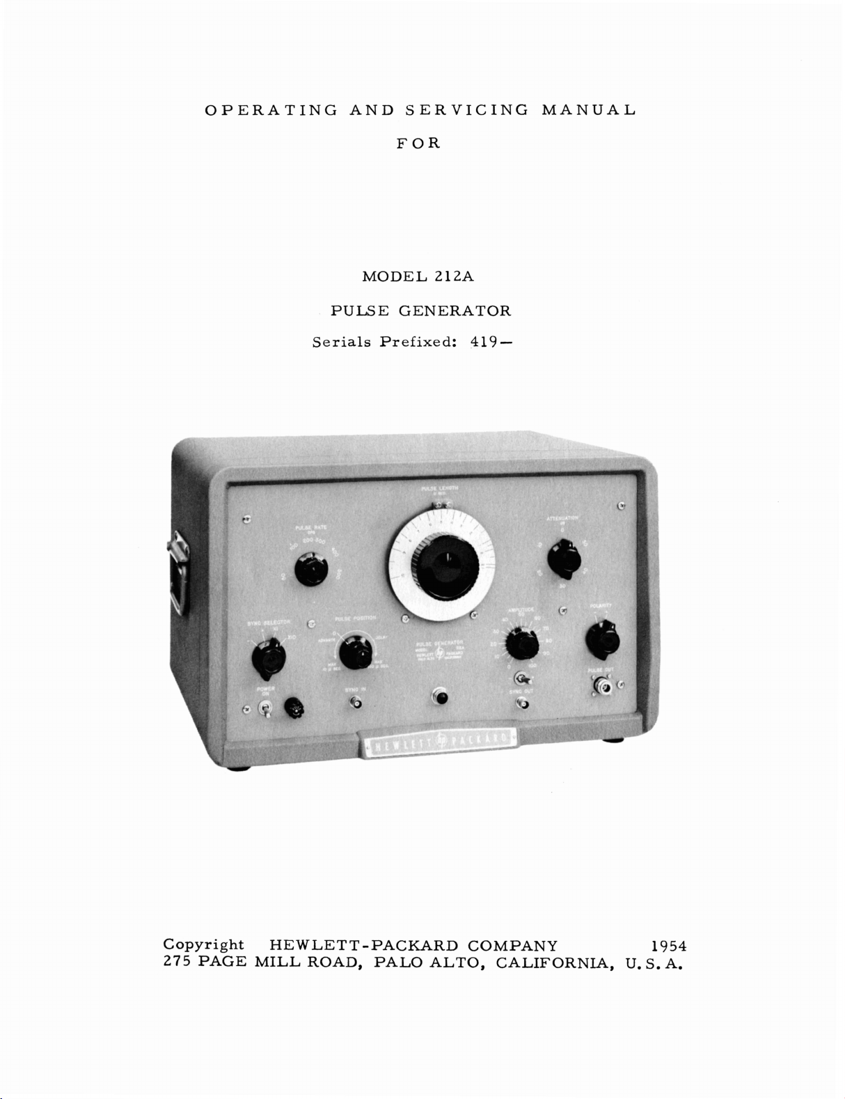
OPERATING AND SERVICING MANUAL
FOR
MODEL 212A
PULSE GENERATOR
Serials Prefixed:
419-
Copyright
275
PAGE MILL ROAD, PAL0 ALTO, CALIFORNIA, U. S. A.
HEWLETT -PACKARD COMPANY
1954
Page 4
SPECIFICATIONS
PULSE
PULSE
PULSE
AMPWTUDE
INTERNAL
REPETITION
PULSE
LENGTH:
AMPLITUDE:
POLARITY:
CONTROL:
PULSE
SHAPE:
JITTER:
IMPEDANCE:
RATE:
SYNC
SYNC
OUT:
POSITION:
IN:
At
least
0.07
At
least
50
volts
Positive
(a)
(b)
(a)
(b)
Less
50
(a)
(b)
Positive
(a)
(b)
(c)
(a)
(b)
(c)
or
Negative.
50
db
attenuator,
Cantinuoualy variable
Rise
and
(10% to
Crest
variation
than
0.01
ohms
or
less
Internal
External
or
negative,
25
volt5
Duration,
Rise
time,
Delay,
repetition
Delay.
repetition
Advance,
repetition
to
10
microaeconda,
peak
into
variable
decay
time
approximately
90yoo),
less
than f 5%
microseconds.
on
either
~ynchronization,
8
ynchronization,%Z
poaitive
approximately
approximately
0
to
100
rate
0
to
50
rate
0
to
rate
pulse
5
volts
or
15
microseconds
up
to
2500
micraseconds
up
to
5000
10
microseconds
up
to
5000
50
ohm
in
control
polarity.
50
peak
voIte
negative
1
microsecond
0.25
pps.
pps.
pps.
continuously
load
(50
watts
10
db
steps.
with
range
0.02
of
average
to
5,
000
5,
000
pps.
pps.
to
minimum.
into
microseconds.
after
Bync
after
sync
out
after
sync
variable.
peak
J.
of
at
least
microseconds
peak
amplitude.
2,
000
half
pulse
pulse
out
pulse
ohm
voltage
with
at
out
10
load.
with
with
db.
points.
I
I
POWER
ACCESSORIES
CONNECTORS:
SUPPLY:
(a)
(b)
1151230
DIMENSIONS: Cabinet
Rack
WEIGHT:
Cabinet
Rack
AVAILABLE:
@I
AC-16F
AC-E6K
#17
Rack
Main pulse,
Sync
volts
Mount:
Mount:
Mount:
Mount;
Fittings.
End
Mount).
in,
Type
sync
flO70,
20-314"
19"
58
lbs.
50
lbs,
Cable
Assembly,
Cable
xsaembly,
Frames,
out,
50fb0
wide,
with
N.
Type
cps,
wide,
,
shipping
,
shipping
qype
BNC
handles
BNC.
380
12-314''
10-112"
weight
weight
N
to
for
watts
maximum.
high,
14-31
high,
14-314"
approximately
approximately
Male
to
Type
BNC.
bench
use,
16"
N
(for
deep.
deep.
76
73
Male
21ZAR
lbs.
lba.
Page 5
TABLE
OF
CONTENTS
Page
No.
Section
Section
Section
I
GENERAL
1-1 General 1-1
1-2
LI
OPERATING
1l1
CIRCUIT
DESCRIPTION
............................
Accessory
Inspection
Controls and Terminals
Automatic
Operation
Waveahape
Po~itive
Operation
Operation
DESCRIPTION
General
Rep.RateMV
Delay
Purse
Pulae
Pulse
Pulse
Clipper
Output
Powersupply
Cablem
INSTRUCTIONS
.......................
...........................
Overload
...........................
of
and
Negative
of
Pulse
of
Pulae
Output
Relay
Pulse
Length
Position
................
.............
MV
and
Poeitlon
Forming
Length
Terminating
Amplifier
Blocking
MV
Circuits
MV
and
Thyratron
and
Thyrntron Vl6
............
....a.rn.....
.............
....................
Protection
..............
...................
Pulsa
Output
and
Control
Oscillator
Blocking
Vb
Blocking
Pulse
Levels
Rate
............
Controla
...............
....
Oacillatos
......
O~cillator
.
........
....
1-1
2-1
2-1
2-2
2-2
2-3
2-4
2-4
2-5
Section
SectionV
IV
MAINTENANCE
4-1
4-2
4-3
4-4
4-5
4-6
TABLEOFREPLACEABLEPARTS
OutputPulseAnalyels
Adjuetmenta
Servicing
Thyratron
Replacement
TroubleShaotingChart
..........................
Negative
Replacement
of
......................
High
Voltage
Supply
(V4.
V1Z.
V14.
etc
.....................
Load
Remistor
R7.1
and
R22
.
. .
....................
..................
. ) ....
4
4-1
4-3
2-5
4-5
4-6
4-7
5-1
Page 6
SECTION
I
1-1
GENERAL
The
Model
ment
change.
The
decay
negative
the
and
able
This
counting
filters
generators,
ACCESSORY
AC-16K:
88/U
for
determining
pulse
repetition
output
from
instrument
produced
with a flat
pulses
attenuator
. 07
circuits,
and
band
RG-58
Type
2
12A
rate,
to
CABLES
BNC
GENEML
Pulse
top
are
10
is
pass
/U
male
Generator
the
by
this
and
available
connected
setting.
microseconds.
applicable
television
circuits
50
ohm
connector.
action
instrument
minimum
and
load,
The
to
systems,
and
coaxial
DESCRIPTION
is
a
fundamental
of
circuits
of
overshoot.
the
pulse
sync
pulse
the
testing
pulse
cable
Overall
under
has
a
shape
condition,
length
of
response
modulation
terminated
length
short
is
radar
of
4Bt1.
measuring
conditions
time
Either
is
continuously
video
of
positive
independent
supply
systems,
amplifiers,
of
UHF
each
end
instru-
of
rapid
rise
-and
of
voltages,
vari
nuclear
signal
with
or
-
UG
-
AC-16B:
UG-88/U
on
the
other
AC-
16D:
U
Type
AC-16C:
2
1B
tor
AC-
UG-21B/U
/U
at
other
E6F:
BNG
Type
RG-58
Type
RG-58/U
BNC
end.
male
/U
Overall
connector.
RG-9A/U
N
male
end.
Overall
RG-9A/U
Type N male
50
ohm
coaxial
male
coaxial
50
connector
50
connector
length
cable
ohm
coaxial
length
ohm
coaxial
connectors.
cable
and
45".
terminated
Overall
cable
and
UG
72".
cable
terminated
dual
banana
one
length
terminated
-23B
Overall
/U
terminated
on
one
plug
(3
end
only
with
4411.
one
end
Type N female
on
each
length
72".
end
with
/4"
center)
WG-881
with
connec
end
with
UG-
-
Page 7

Page 8
S
EC
TION
11
2-2
Refer
CONTROLS
PULSE
This
front
SYNC
This
This
ather
+r
This
trols
terminal.
SYNC
The
the
to
terminal
panel.
OUT
terminal
terminal
device
-
toggle
the
IN
SYNC
panel.
the
OUT
polarity
generating
Warranty
AND
is
a
It
is
is
a
provides
for
use
switch,
IN
terminal
A
voltage
circuit.
OPERATING
sheet
TERMINALS
Type
the
output
BNG
a
with
on
the
of
the
is4a
can
in
N
jack
connection
terminal
voltage
the
panel
synchronizing
BNC
be
fed
INSTRUCTIONS
this
manual,
located
on
to
Pulse
above the
connector
into
at
for
the
synchronize
Generator.
voltage
this
the
the
lower
SYNC
on
terminal
lower
main
right
an
OUT
fed
the
right
pulse.
side
of
osciLloscope
terminal,
to
the
SYNC
lower
to
left
trigger
corner
the
side
the
of
panel.
or
con-
OUT
of
pulse
the
SYNC
The
pulse
chronization
sync
PULSE
The
PUlSE
poaition
loscope
PULSE
The
panel,
per
SELECTOR
SELECTOR
SYNC
rates,
pulses.
POSITION
PULSE
OUTPUT
the
has
RATE
PULSE
adjusts
second
SELECTOR
and
also
from
either
POSITION
and
the
main
been
RATE
in
switch.
pulse
synchronized
control,
the
repetition
conjunction with
knob
selects
control
selects
positive
SYNC
on
an
located
rates
two
ranges
necessary
or
negative
adjusts
the
OUTPUT
oscilloscope
with
the
SYNC
on
the
of
the
the
X1
and
circuitry
externally
timing
pulse.
screen
OUT
upper
pulse
X10
from
position
of internally
for
external
generated
between
Its
main
when
left
pulse.
hand
50
of
the
to
the
generated
syn-
the
MAIN
use
is
to
oscil-
side
of
the
5000
cycles
SYNC
Page 9
PULSE
The
and
WIDTH
PULSE
controls
WIDTH
the
AMPLITUDE
The
AMPLITUDE
PUT
pulse.
ATTENUATION
The
ATTENUATION
provides
of
pulse
attenuation
output can
POLARITY
The
POLARITY'control
the
polarity
FUSE
The
fuseholder,
4
ampere
power
replaced
transformer
of
cartridge
by
unscrewing
width
the
on
control
of
control
control,
of
the
be
obtained.
MAIN
the
panel
fuse.
is
connected
is
the
the
MAIN OUTPUT
gives
located
Main
at
the
lower
OUTPUT
next
A
2
ampere
the
fuseholder
large
a
continuous
an
pulse
right
pulse
to
the
for
230V
dial
the
in
10
hand
from
POWER
fuse
should
operation.
cap
and
at
the
center
pulse.
variation af
right
db
hand
steps
side
positive
ON
be
inserting
so
of
switch,
used
The
of
the
side
that
the
panel
to
negative.
fuse
a
new
the
panel
MAIN
of
the panel,
low
levels
switches
contains
when
the
may
fuse.
OUT-
a
be
2-3
AUTOMATIC
An
overload
thyratron
Operation
when
sufficient
sition
then
The
1.
place
Model
Plug
line
when
Allow
2.
if,
the
instrument
warm-up
without
the
and
the
of
the
21ZA
several
SELECTOR
unit
can
3.
allow
Connect
This
about
connection
OVERLOAD
relay
for
the
any
relay
any
external
is
incorporated
reason,
is
is
and
instrument
Pulse
power
turn
swftch
in
be
used
ten
the
equipment
on
Generator
cable
the
is
minutes
the
t
after
minutes
should
RELAY
continuous plate
indicated
first
turned
turning
the
triggering
in
normal
into
a
nominal
toggle
on.
or - position
switch.
)
for
the instrument
2
or
3
warm
to
be
be
made,
PROTECTION
in
the
instrument
by a buzzing
on,
it
may
SYNC
operating
is
operated
SELECTOR
for
two
115V,
(The
and
with
minutes
up
driven
of
warm
time
if
if
to
the
possible,
current
sound,
indicate
or
three
condition.
as
follows:
50
to
pilot
possible.
to
warm
no
lamp
sync
up,
PULSE
through
to
protect
conduction
If
this
that
there
to
the
+
minutes
60
cycles
should light
up
with
in,
Although the
it
is
desirable
OUT
terminal.
a
nominal
the
@
occurs.
occurs
is
in-
or
-
po-
should
power
the
SYNC
45~
to
Page 10
50
ohm
The
proximately
50
If
the
of
20
ated
from
true
set
OUTPUT
ing
The
SYNC
minals
be
switched to
should
dial
then
control
on
by
to
be
set
be
the
oscilloscope
means
give
cable.
output circuit
50
ohms
for
in
on
to
set
is
the
is
not
overall
to
30
megacycles,
in
a
non-inductive
the
load
when
the
full
output.
source
an
imperfect
OUT
an
set
the
then
of
terminal
oscilloscope
select
to
either
desired
to
select
adjusted
the
AMPLITUDE
desired
of
the
Model
ohms
absolutely
system
which
se
termination
necessary
is
sensitive
the
50
ohm
may
cause
ATTENUATION
Under
impedence
output
may
the
best
the
repetition
the
pulse
until
screen.
these
cable
be
and
the
performance.
XI
or
width
the
The
CONTROL
output
level.
212A
is
of
fox
to
frequencies
output
is
connected
cable
load
to
ringing.
and
OUTPUT
conditions
less
than
termination
polarity
the
X10
position,
rate,
The
desired
pulse
amplitude
appears
arrd
terminated
the
output
many
should
prevent
This
controls
the
50
ohms
at
to
the
synchronizing
of
the
SY
The
SYNC
PULSE
and
the
at
of
the
the
OUTPUT
with
ap-
cable
measurements.
on
be
reflections
is
especially
Model
thus
the
NC
with
the
order
termin--
are
Z12A
result-
source
OUT
SELECTOR
and
the
PULSE
WIDTH
PULSE
the
desired
pulse
dial
POSITION
can
be
ATTENUATOR
end,
ter
signal
may
position
adjusted
-
may
RATE
2-5
Do
than
5000
seconds
2500
must
creased
position
WAVESHAPE
The
output
and,
in
operating
erator
the
generator
the
internal
condition
attenuation
pulse
general,
conditions
is
operated
impedance
may
is
not
set
the
50
micreseconds
cps
is
used.
may
be
cps,
be
OF
and
be
increased,
Above
decreased
so
as
circuit.
OUTPUT
from
the
the
waveshape
of
the
at
zero
an
unterminated
of
corrected
CAUTION
PULSE
Maximum
used
2500
as
not
to
overload
PULSE
Model
Pulse
attenuation,
the
generator
by
properly
the
internal
POSITION
when
for
cps
the
2
is
Generator.
a
repetition
the
repetition
1
ZA
has
quite
with
load,
impedance
delay
repetition
delay
maximum
the
tubes
extremely
independent
of
1015
rates
rate
to
greater
rate
micro-
up
delay
is
in
the
of
However,
a
length
reflections
being
terminating the
less
of
may
than
approaches
I
of
to
in-
pulse
good
wave
the
when
cable between
occur
50
ohms.
cable,
load
50
shape
and
the
due
As
ohms,
the
gen-
to
This
the
Page 11
The
waveshape
bout
50
control,
is
desired,
and
operate
as
possible.
The
AMPLITUDE
the
circuit,
put
terminals
of
the
AMPLITUDE
put.
to
imum
Unless
operate
position.
volts
the
is
of
waveshape
it
is
the
there
into
this
the
unit
little deterioration
best
output.
preferable
with the
As
the amplitude
deteriorates
to reduce the
AMPLITUDE
control
will
a
50
control
additional
with
In
some
with
is
be
at
ohm
will
output
the
AMPLITUDE
cases
the
AMPLITUDE
AMPLITUDE
slightly
control
not
calibrated, but,
least
load.
give
the
as
50
volts
On
appreciably
is
absolutely
pulse
control
is
reduced
and,
output
close to the
peak
most
units,
control
output
control
set
to
provide
with
the
AMPLITUDE
if
the
best
waveshape
level
available
necessary, it
with
the
50
volts
with
no
attenuation
from
the
maximum
more
than
SO
slightly below
attenuator
position
the
position
volts out-
is
desirable
the
waveshape will show
at
full
maximum.
a-
in
out-
max-
a
2-6
2-7
POSITIVE
The
positive
equal
panel.
same
plitude
OPERATION
The
pulse
10
microseconds.
is
convenient
tures
adjustable
between
output
With
a
can
this excellent flexibility
little
be
pulse
tained
it
is
desirable
the
pulse
tion
in
AND
and
and
either
These
value
and
between
OF
length
for
of
this
instrument.
pulses involves
two
larger
pulse duration,
sacrifice
expected
lengths
from
where
time
length to
the
pulse
drogen thyratron
the
equipment,
there
age
behind
may
over
the
be
a
period
main
some
NEGATIVE
negative
can
be
outputs,
it
is
normal
the
positive
PULSE
is
adjustable
This
a
great
time
in
absolute
to
be
correct
considerably
to
time.
to
use
some
the
length
tubes
some
change
change
of
time.
pulse
PUUE
pulse
selected
however,
that
and
LENGTH
from
continuously
many
applications
The
generation
a
differential operation whereby
periods
in
accuracy.
within
Where
sort
correct
is
used
the
in
in
in
value.
variation
the equipment,
pulse
the
Controls
dial
so
that
OUTPUT
outputs
by
cannot
there
negative
AND
are
means
be
will
PULSE
less
adjustable
is
used
to
the control
In
f
10
percent
more
accurate
of
pulse
the
variation
an
auxiliary
One
in
length
length calibration
are
pulse
LEVELS
adjusted
of
the switch
expected
be
output
than
.
and
of
these very
control
of
general
a
position.
RATE
07
the
to
to
little
of
a
feature
is
one
the
pulse
the
except
in
the
be
have
difference
CONTROLS
microsecond
of
short,
actual
output,
pulse
for
length
pulse lengths
calibrating
of
the
main
causes
the characteristics
As
tubes
will
be
obtained,
provided
length
on
the chassis
calibration
approximately
on
the
front
exactly
in
in
the
Model
the
useful
continuously
the
diff
time
there
length
very
short
may
are
necessary,
means
of
varia-
of
the
are
changed
and
as
the
tubes
just
can
the
am-
to
2
fea-
esence
of
the
control
be
to
set
hy;
in
also
be
reset
1
is
ob-
ZA
Page 12

from
the
The
except
sate
The
the
in
it
The
5
it
use
ing
time
adjustment
length
is
internal
range
general,
is
preferable
Model
volt
amplitude
is
desired
a
wave
voltage.
Square
for
a
sine
It
is
important
of
5000
by
the
duty
petition
have
a
to
of
that
the
changed
repetition
from
hold
2L2A
to
shaper
Wave
wave
cycles
cycle
rate
at
time-of
time
of
the
pulse
if
necessary.
these
main
pulse
length
especially
50 to 5000
within
to
use
an
can
be
and a rise
synchronize
of
some
The
unit
synchronizes
Generator.
input
that
/sec.
the
-rise
is
the
Performance
of
the
low
in
the
See
controls.
is
essentially
will
tend
above
rate
cycles
f
2
570,
external
repetition
generator
/set.
but
when
oscillator
synchronized
time
in
the
from a sine
sort
to
increase
very
Another
show
Model
in
Figure
212A
typical
not
at
thyratrons,
frequency
order
end
of
one
Section
to
change
is
IV,
independent
rates
a
rnultivibrator
Calibration
accurate
to
from
external
order
wave
of
the
well
waveshaper
2-1.
be
driven
this
end
There
is
provided
or
two
Maintenance,
of
the
slightly
of
repetition
drive
a
microsecond
source,
rise
from
at
of
the
practically
the
microseconds,
as
the
1
kc.
adjustable
of
this
cohtrol should,
rates
the
pulse
pulses
time
an
a
pulse
range
synchronizing
having
it
is
necessary
of
@
Model
which
is
no
the
may
rate
limit
regarding
other
repetition
controls
over
are
generator.
at
or
two. If
synchroniz-
21
1A
be
in
excess
limited
to
pulses
desired,
least
a
to
used
mainly
the
re-
2-8
Since
widths,-
rates
the
have
and
OPERATION
The
around
of
the
unit
there
especially
pulse
width
been
for
most
PULSE
the
the
sync
incorporated
purposes
OF
POSITION
SYNC
out
approximately
use
is
to
position
position
dition
ing
will
is
normal
conditions.
tend
is
limited
is
a
tendency
when
is
at
the
the
in
they
PUISE
control
OUT
by
100
and
See
timing.
approximately
microseconds.
the
main
to
be
affected
should
important
by
duty
for
the
repetition
maximum
the
unit
are
not
POSITION
is
This
pulse
to
cause
precaution
cycle
at
amplitude
rate
value.
to
minimize
serious.
CONTROL
designed
control
10
microseconds
This
on
an
oscilloscope
some
no
serious
high
repetition
to
is
above
However,
these
to
adjust
will
control
extent
by
difficulty
given
be
affected
1000
the
set
or
is
not
screen.
the
at
the
rates
and
by
cycles/sec
compensating
amplitude
main
the
after
main
the
pulse
pulse
calibrated
This
pulse
under
end
rate.
normal
of
paragraph
long
pulse
repetition
and
when
circuits
variations
timing
ahead
sync
as
out
its
by
main
pulse
This
con-
operat-
2-4.
Page 13
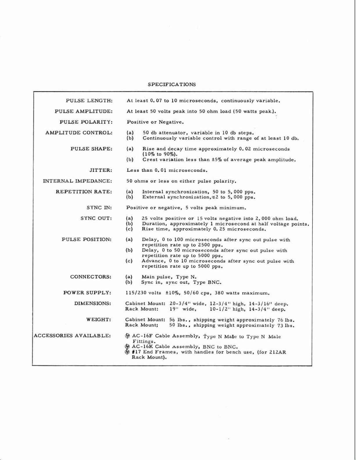
12AXT
OR
6SL7
WF
-
TO
SYNC
IN
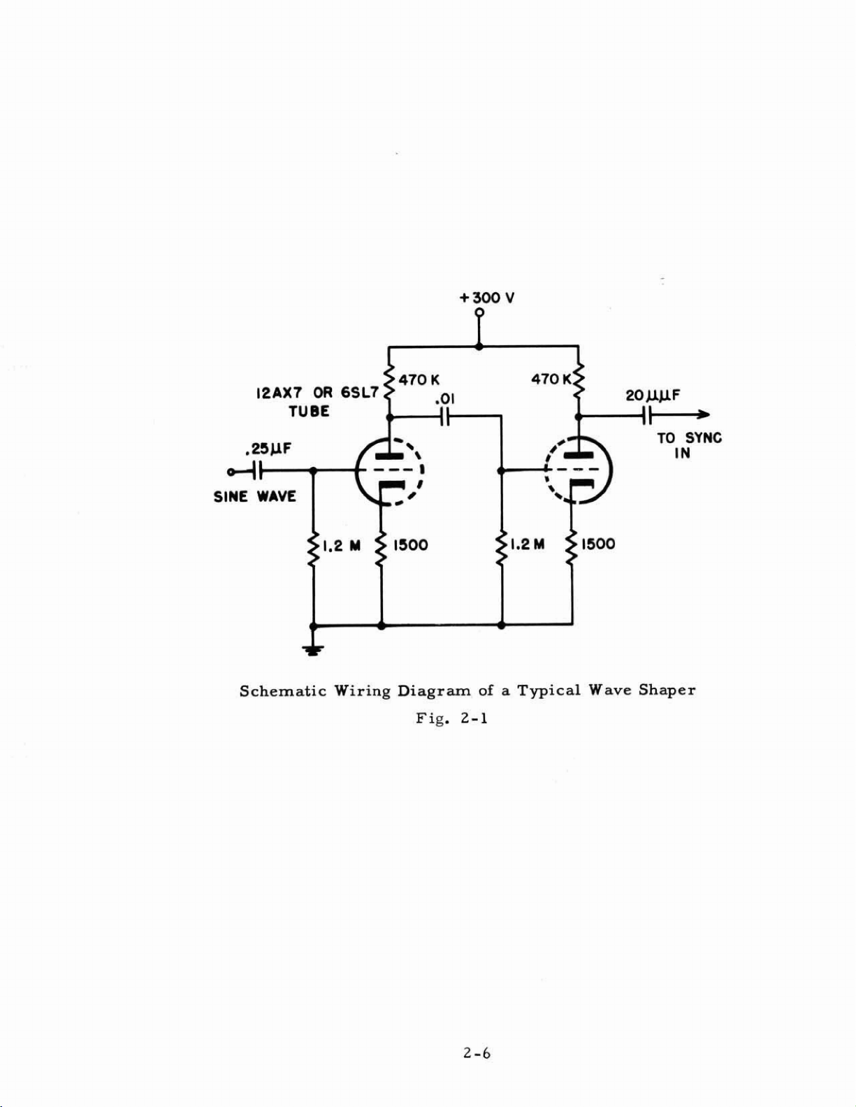
Schematic
Wiring
Diagram
Fig.
of
2-1
a
Typical
Wave
Shaper
Page 14
SECTION
ZIL
3-2
GENERAL
The
Model
triggering
generating
rear
eratin'g circuits
cuits
diagram
the
deck.
are
following
REP.
This
a
V103B
pulse
The
operated
free
5000
may
section
multivibrator.
to
repetition
running
pulses
be
212A
circuits
circuits,
The
located
and
the
circuit description.
RATE
in
MV
of
conjunction
the
input
either
condition
per
externally
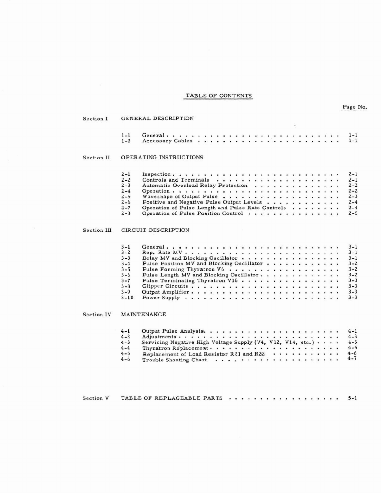
CIRCUIT
Pulse
block
are
to
schematic
the
The
of
rate
free
second
Generator
which
and
diagram
shown
the
circuit
amplifier
with
the
multivibrator
running
it
triggered up
DESCRIPTION
consists
are
located
the
power
of
the
in
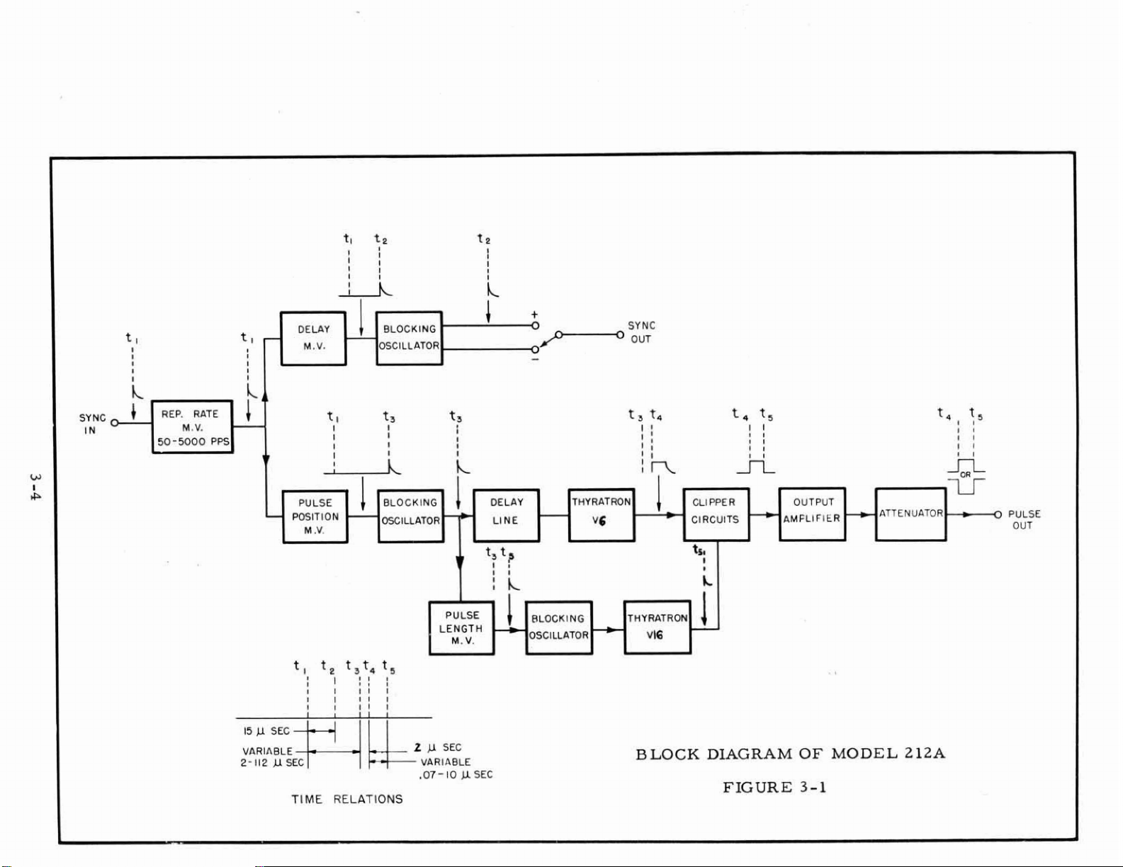
Figure
left
of
the
thyratrons
wiring
consists
tube
switch
multivibratoP.
generates
or
in
S102A
consists
or
triggered
the
externally
to
5000
in
the
supply
triggering
3-1.
diagram
of
an
V103A
are
pulses
pulses
of
three
front
which
A11
V6
will
amplifier,
and
used
of
tube
by
an
at
the
basic
deck,
are
and
of
the
and
both
the
phase
to
deliver
V104AB
external
repetition
synchronized
per
second.
parts,
the
main
located
main
triggering
V16.
be
phase
pulse
This
referred
inverter,
inverter
a
and
pulse.
rate
condition
the
pulse
in
the
gen-
cir-
block
to
in
tube
negative
may
be
In
the
of
50-
it
and
3-3
When
that
The
multivibrator
DELAY
Tube
from
to
The
ing
The
supplied
reversing
the
it
generates
pulses
MY
VlOlAB
the
repetition
produce
trailing
oscillator.
blocking
to
rnultivibrator
switch.
a
pulse
generated
and
the
AND
a
BLOCKING
is
employed
positive
edge
of
rate
the
oscillator
the
sync
out terminals
is
externally
only
when
by
this multivibrator
pulse
position
OSCILLATOR
as
a
"one
multivibrator
15
microsecond
15
microsecond
tube
V102B
synchronized,
triggered
multivibrator.
shot1'
by
are supplied
multivibrator,
triggers
forms
of
the
pulse
which
pulse
instrument
the
then
sync
the
the
is
triggers
out
it
is
biased
external
to
delay
multivibrator
inverted
pulse
through
pulse.
the
The
by
the
which
a
so
delay
pulse
VlOZA.
block-
is
polarity
Page 15
3-4
PULSE
The
pulse
brator
brator.
this
multivibrator.
able
resistor
The
blocking
the
pulse
ing
oscillator
ing
oscillator
crystal
from
cathode
the
POSITION
position
which
A
positive
is
R132.
oscillator
length
is
to
rectifier
delay
to
grid
MY
AND
multivibrator
triggered
pulse
The
tube
multivibrator
a
cathode
the
delay
CR104
line
and
being
capacity
BLOCKING
by
the
2
to
ll2
duration
V
106B
and
follower
line,
a
resistor
fed
to
of
V107B.
OSCILLATOR
tube
V105AB
pulse
In
from
microseconds
of
this
forms
the
delay
tube
series
the
pulse
the
line.
VlO7B
with
R152
the
blocking
is
also a one
repetition
in
length
is
controlled
pulse
which
Following
which
the
which
couples
grid
prevent
oscillator
shot
rate
is
produced
by
is
supplied
the
the
of
this
reflections
circuit
rnultivi-
multivithe
vari-
block-
block-
tube
is
due
to
by
to
a
the
3-5
3-6
PULSE
Tube
LZ
plied
draws
voltage
When
lator
tube
V2, which
are
used
to
excessive
to
the
and
is
fired,
voltage,
line.
10
the
action
the
The
PULSE
The
V
brator
PULSE
The
rnicroseconda
open
limits
cathode
damping
LENGTH
positive
107A.
consisting
LENGTH
FORMING
is
to
charge
the
pulse
the
grid
pulse
delay
until
forming
line
it
will
the
pulse
end
of
the
the
resistor
diode
pulse
The
negative
THYRATRON
normally
the
pulse
forming
current,
of
will
continue
conduction
forming
due
line
tube
R13.
tube
MV
AND
from
of
V108A
control
thyratron
then
the
tube
line
trigger
line
to
a
reverse
and
conduction
V3
BLOCKING
the
pulse
(R142).
Vb
connected
forming
the
V2
thereby
is
charged,
the
to
carry
is
quenched
causes
is
reflected
and
is
used
blocking oscillator
from
and
V107A
V108B.
as
a
diode,
line
Vb.
If
for
relay REL-1
stopping
a
pulse
thyratron
current,
by
means
the
plate
polarity
transient
back
forms
to
damp
OSCILLATOR
a
out
triggers
The
pulse
and
so
that
any
reason
applies
the
from
tube.
irrespective
of
voltage
to
the
starting
10
microsecand
any
negative
Vl
ObB
the
length
the
plate
a
large
flow
the
blocking
Once
the
pulse
to
fall
which
is
inverted
pulse
is
charging
voltage
the
thyratron
choke
is
negative
of current
oscil-
the
thyratron
of
the
grid
forming
to
zero
travels
point.
pulse
down
This
across
overshoots.
by
length
varied
multivi-
by
ap-
to
V6.
after
to
tube
the
The
trailing
blocking
on
to
the
edge
of
oscillator
thyratron
the
negative
V109A.
V16
through
The
the
pulse
output
cathode
from
of
the
the
multivibrator
blocking
follower
oscillator
tube
V109B.
triggers
is
the
passed
Page 16
3-7
PULSE
The
pulse
When
presents
ratron
fired,
TERMINATING
a
V6
from
and
this
very
tube
V109B
thyratron
low
impedance
causes
THYRATRONVlb
a
rapid
triggers
in
conjunction
to
fall
the
of
the
the
pulse terminating
with the
pulse
pulse
from
to
the
form
thyratron
discharge
pulse
the
forming
trailing
diode
edge.
Vlb.
V8
thy-
3-8
3-9
Additional
allows
set
the
the pulse terminating thyratron
to
a
very
thyratron
CLIPPER
The
pulse
pers
clipper.
OUTPUT
The
plus
attenuator
and
output
or
minus
then
Tube
AMPLIFIER
Intermediate
TUDE
This
grid
ode
control
control
bias
and
voltage
direct
low
V16
current
value.
to
CIRCUITS
from
the
to
the
V9
amplifier
is
pulse
is
then
used
values
which
consists
plate
on
the
two
voltage
Tube
be
extinguished
thyratron
output
the
tube V11
may
a£
has
of
voltage
amplifier
second
be
selected
to
reduce
amplitude
a
continuous
two
ganged
on
clipper
is
supplied
to
V8
in
conjunction
at
the
is
sent
through
tube
and third diode
feeds
the
and
the
pulse
may
polarity
be
range
variable
the
output
tubes
V7
and
to
fire
when
end
of
a
series
V
11.
applied
10
db
selected
of
more
resistors
amplifier
V9.
Vlb
by
the
with
the
Tube
clipper.
switch
to
the
steps.
by
tube
means
pulse
R10
and
pulse
of
three
V7
is
where
attenuator.
means
than
10
which
V11
of
R28
length
C24
cycle.
diode
the
first diode
either
of
the
db.
vary
and
the
and
is
allows
clip-
a
The
AMPLI-
the
cath-
In
order
in
repetition
in
the
age
to
the
compensating
rate
The
voltages
V12,
and
gulate
to
unit.
is
applied
plate
or
pulse
power supply
are
VL4)
V17B
the
are
voltage
provide
rate
When
to
of
the output
for
width
regulated
or
by
used
a
more
and
pulse
the
rate
the
cathode
the
otherwise
is
increased.
circuits
either
electronic
to
regulate
supplied
constant
width,
or
pulse
of
V15
tube
and
decrease
are
conventional,
by
glow
regulators
the
to
the
pulse
a
compensation
width
through
bias
of
discharge
(VlOB,
t300V
clipper
output amplitude
circuit
is
increased,
R51
which
the
clippers
in
output amplitude
and
the
type
VL7A,
supply.
and
output
to
direct
regulator tubes
V17B).
Tubes
amplifier
with
is
incorporated
a
positive
causes
increase
when
current
Tubes
V15
andV17
circuits.
changes
volt-
the
voltage
thereby
the
supply
(V4,
VlOF
re-
Page 17
50
-5000
PPS
tl
I
1
I
I
I
-
1
-
OEUY
M.V.
t
I
I
I
a
PULSE
POSITION
M
.V.
BLOCKING
OSCILLATOR.
l
t3
I
I
BLOCKlNG
WILLATOR
ts
1
I
I
I
1
t t
1r
DELlllY
LINE
?
P
I I
!
IL
-
k
THYAATRON
-
Vg
SYNC
OUT
t,
t4
:
I
I
in
t4
CLIPPER
CIRCUITS
t
r
I
L
2,
I
I
I I
I
I
ri
+
*
OUTPUT
AMFLIFIER
RTTENULITOR
tal
1
I1
I
I I
4L
u
=
f5
fl
0
PULSE
OUT
VARIABLE
PULSE
LENGTH
M.
V.
I1
I
I
I
I
I
I I1
f
l
ME
RELATIONS
II
I
I
I
WRIABLE
.O7-
I0
Y
SEC
RLOCKI
NG
OSCILLATOR
THY
RATRON
BLOCK
DLAGRAM
FIGURE
OF
3-1
MODEL
Z12A
Page 18
SECTION
IV
MAINTENANCE
4-1
OUTPUT
The
output
three
Each
of
the
part
trouble
Leadin
1
7B
?7+--
Only
the
leadin
PULSE
parts:
part
output
of
the
shooting
Ed
trrggers
the
circuits
&uch
F-
ective
and
Overshoot
of
is
generator.
Very
ponent
compensates
positive
from
pulses
pensation
The
ment
observing
shape.
greater
chart.
tube, crystal
VlOTS.
the
pulse
usually caused
minor
construction,
output
thyratron
and
is
setting
is
accomplished
C11
portion
ANALYSIS
pulse
is
pulse
of
the
leading
affected
pulse,
is
chart
e
--
V6,
V6
of
ed
e
of
See
items
--
Overshoot
than
on
by
overshoot
for
this
pulses.
V6
to
the
cathode
controlled
of
each
both
positive
is
generally
of
the
the
Model 2 12A
edge,
by
different
it
will
generally
described
follows
the
rstart'
and
V6
forms
V6
and
V107B
the
output
as
jitter
diode,
2,3,
pulse.
and
or
and 4 of
occurs
the
trailing
leads
wiring
overshoot
and
capacitor
used
coming
and
This
couples
by
by
andnegative
adjustment.
tube
circuit
adjustable
affects
alternately
set
near minimum
Pulse
the
top
circuits.
indicate
separately
the
same
thyratron,
the
leading
are
A
slowness,
other
to
component
trouble
a
greater
edge.
for
external connections
from
the
lead
on
the
amplifies
it
to
for
positive
length
the
ceramic
that
adjusting
pulses.
See
Generator
or
body,
and
general
responsible
defect
If
a
the
the
"urns
edge
that
is
the
and
defect
list
order.
in
shooting
degree
Overshoot
pulse
leading
plate
generator
within
edges
a
portion
circuit
pulses.
capacitors
of
the
other,
the
Adjust
capacity.
item
5
of
will
the
trailing
appears
circuit
of
symptoms
ont
the
of
the
for
the
appears
direct
the
circuits
chart.
on
the
greater
is
the
instrument,
of
both
of
of
The
The
two
capacitors
for
C22
the
trouble
be
divided
at
fault.
output
output
condition
on
the
result
leading
than
specified
to
the
caused
negative
the
rise
V11
for
degree
C
1
1
and
final
optimum
is
used
shooting
into
edge.
on
apart
Each
in
pulse.
pulse.
of
lead-
of
a
de
of
V6
edge
pulse
by
Vl
time
negative
of
C22.
adjust-
while
pulse
for
the
-
com-
OA
and
com-
a
To of
-time plate
the
ly
will
The
500
Pulse
supply
11
micraseconds
not
fire
pulse
volts.
generated
--
When
is
constructed to
from
until
re-triggered.
by
Clippers
V7
V6
is
voltage
the
V6
is
and
triggered,
supplied
momentarily
time
very
V9
clip
it
to
V6
fires.
coarse
the
amplitude
generates
this
tube.
stop
power
V6
is
and
contains
a
pulse
To
delivery
then
peaks
to
between
limited
protect
approximate-
extinguished
in
250
in
Yb,
and
excess
and
of
350
Page 19
volts
pulse
is
the
V 1 1.
plitude
pulse.
The
high
in
voltage
If
it would
ing
be a matter
ing
depending
is
now
biased
top
portion
The
that
See
body
voltage
the
pulse
supply.
the
pulse
indicate
chart.
chart.
well
formed
very
would
items
of
the
supply
body
contains
When
of
upon
beyond
of
high
final output pulse depends
adjustment
setting
for
application
cutoff.
the clipped
bias
on
otherwise
24
and
25
to
maintain
generally
See
item
peaks
ineffective
the
top
has
of
the
As
pulse
V
1
1
appear
in
trouble
indicates
b
of
trouble
or
humps
clipping,
a
gradual
and
is
AMPLITUDE
to
a
result
generated
removes
on the
high
covered
the
shooting
initial
a
defective
shooting
above
see
rise
output
of
the
high
by
unwanted
baseline
chart.
upon
items
in
sufficient
pulse
chart.
the
normal
or
drop,
item
7
control.
amplifier
bias
Vb
is
A
V11.
voltage
passed
signals
fallowing
power
amplitude.
component
level
and
8
of
trouble
the
correction
11
of
the
trouble
flat-top
through
of
low
the
from
A
droop
in
the
of
the
V11
only
am
output
high-
top,
shoot-
may
shoot-
-
the
in
Trailing
When
g
er
multivibrator
trailing
with
on
the
s
hooting
V16
pulse
'stop'
trailing
Edge
is
for
edge
chart.
t'Both'Edges
both
leading
in
a
circuit
All
circuits
and
trailing
Pulse
crease
there
and
the
rate.
If
cause
the
trouble
Length
in
rate
is
a
very
the
time
duty
cycle.
Generally,
the
start
the
output
output pulse
shooting
--
V16
triggered,
the
stop
V
1
OS
and
is the
thyratron
of
and
which
preceding
edges
--
edge
Output
trailing
affects
and
A
change
is
generally
result
of
small
the
gas
is
This
the
tube
has
this characteristic,
pulse
will
lengthen
chart.
the
'stopt
it
forms
tube
blocking
of
V16.
the output pulse.
Pulse
edges
both
V107b,
do
not
in
time
characterisitic
time
lapse
fully
lapse
to
shorten.
thyratron, 'turns off' the output
the
is
developed
oscillator
all
these
The
effects
--
If
a
trouble
of the output pulse,
start
and
(V101
affect
pulse
due
ionized.
one
length
to
one
-
between
increases
If
with
an
trailing
by
the
V
circuits,
of
these circuits
See
such
stop
through
edge
caused
of
the
the
The
degree
causes
with
an
increase
the
stop
increase
edge
of
the
circuits
l09a.
items
plus
as
The
V8
13
'jitter'
the
thyratrons
V
106b)
without
thyratrons.
time the
the
tube
in
affect
affecting the
by
an
of
time
pulse
an
increase
has
rate.
pulse.
pulse.
of
amplifier 107a,
condition
which
can
and
14
appears
defect
The
of
is
In
appear
of
trouble
is
generally
simultaneously.
both
leading
other.
increase
In
tube
length
in
pulse
this
See
is
lapse
or
some
thyratrons
triggered
depends
to
vary
in
duty
rate
characteristic,
item
17
trig-
the
series
only
-
on
de-
with
cycle.
will
of
on
High
The
pulse
symptoms
higher
pulse
rates
rates.
tax
both
of
a
failing thyratron
thyratrons
to
a
greater
therefore
degree
become
than
low
rates.
more noticeable
at
Page 20

The
greatest
pulse
the
will
to
to
which
trailing
A
with
rate
longest
be most
microphonica.
try
several
gives
quick
a
12AU7
V105.
duty
cycle
and
minimum
period
of
subject
--
Microphonic s usually
ultivibrator tubes
When
new
tubes
the
required
edge
operational
only
not
would
check
in
a
for
pulse
time.
to
jitter
changing
to
advance
indicate
for
critical
the
stop
length.
Under
and
VlOl
obtain
L2AU7
circuit,
thyratron,
At
these
slowness.
appear
and
V105
VlOl
one
and
that
and
which
delay.
VlO8
tubes
any
Vlb,
that time
conditions
as
a
are
particularly
V105,
is
is
can
position
it
not
A
small
microphonic.
be
made
occurs
it
is
the
stop
small
may
microphonic
jump
other
at
maximum
conducting
thyratren
jump
be
by
than
in
subject
necessary
in
the
.
exchanging
Vl
pulse
and
Ol
for
or
Interference
can
occur
connecting
ondary
visual indication
on
~inging
Zn
was
tained
an
the
2
ADJUSTMENTS
Pulse
e
d
windings.
a
very
at
some
constructed
a
instrument
line
Length Calibration
to
the
position
use.
mately
An
Following
The
correct
external
calibration
sary,
fallows:
the
Through
when
to
the
high
the leading
models
line
filter
is
filter
circuit
instruments
sensitivity oscilloscope.
of
without
known
line
The
may
the
which
Power
do
not
interference
be
seen
and
212A
an
is
to
shown
--
potentiometer in the
potentiometers
calibration
alter
time
replacement of
of
dial
standard
the
PUZSE
calibration
vary
of
the
the
potentiometer
LENGTH
Line
on
the
have
shields
when
trailing
edges
Pulse
internal
not
shown
cause
interference
at
the
The
PULSE
pulse
greatly
PULSE
is
necessary
a
component
may
be
adjusted
--
Interference through
line
are
not
filtered
between
may
appear
viewing
Generator the
shield,
in
very
The
of
the
Some
the
schematic
the
in
low
interference
pulse.
filament
through
rear
of
the
manual
LENGTH
length
in
LENGTH
dial
multivibrator
taper
has
been
where
within
should
for
and
can
dial
will
replaced
high
the
circuits
be
checked,
greater
the
power
or
if
transformers
primary
and
various forms.
amplitude pulses
will
cause
transformer
of
these
models
diagrams.
the
dial
power
should
is
hand
line,
be added.
calibrat-
circuit.
change
be
accuracy
accuracy
taper
onlyapproxi-
or
has
is
required.
V108
the
If
neces-
as
line
sec-
A
con-
If
Com-
after
aged.
1.
With
the
If
2.
microseconds.
pulse
PULSE
necessary,
generator
LENGTH
adjust
connected
dial
to
1Q.
C128
to
obtain
to
a
calibrated
a
pulse length
oscilloscope, set
of
exactly
10
Page 21

3.
4.
5.
6.
Set
PULSE
If
necessary,
Check
the
curacy.
I£
of
accuracy
shaft
unable
R142,
LENGTHdial
adjust
and
the
to
bring
recalibration
RL43
of
other
above
close
to
.1.
to
obtain
points
adjustments
enough,
of
a
new
on
dial
dial.
particularly
a
pulse
The
refined
will
be
length
for
following
required.
of
dial
may
greatest
. 1
microsecond.
be
slipped
overall
replacement
on
ac
-
Pulse
proximate
meant
1.
2.
3.
4.
Rate
With
position
Adjust
With
to
Adjust
and
the
X10
Set
5.
petition
lrlOO1l.
Check
6,
the
Pulse
PULSE
tained
Position Calibration
by
Calibration
setting
to
have
the
R124
PULSE
the
Xl
R121
R121
desired
ranges.
PULSE
other
above
-ON
slipping
of
the
high
accuracy.
equipment
and
the
PULSE
toobtainapdse
RATE
position.
to
obtain
are
interdependent.
maxirriurn
RATE
rate
of
1000
Tighten
settings
set
points
control.
the
--
The
repetition
operating
control
a
pulse
dial
pps.
screw
on
the
for
beet
dial
on
PULSE
Adjust
UTE
unchanged
pulse
rates
and
SYNC
Loosen
lightly.
dial
compromise
--
No
The
position
the
RATE
frequency
as
follows:
set
SYNC
dial
to
rate
of
5000
rate
of
520
Steps
2
are
SELECTOR
set
for
accuracy
adjustments
of
shaft
to
the
dial
is
used
and
its
SELECTOR
maximum clockwise
to
5200pps.
set
SYNC
pps.
and
obtained
screw
on
are
"01'
correct
The
4
must
on
switch
in
dial
of
calibration.
overall
provided
delay
only
for
calibration
switch
SELECTOR
settings
be
repeated
both
the
to
obtain a re
and
set
accuracy,
for
or
advance
position.
ap
-
is
not
to
the
position.
switch
of
R124
until
X1
and
to
read
Readjust
setting
is
ob-
XI0
-
the
The
maximum
The
maximum
delay
advance
At
maximum
50
microseconds,
ratea
in
obtainable
rate
excess
depends
obtainable
NOTE
do
not
use
or,
at
max.
of
2500
pps.
depends
delays
delay
on
V
105.
on
VIOL.
in
excess
do
not
of
use
Page 22

Power
adjusted
eter.
made
Supply
by
Following
as
follows:
Adjustment
varying
service
the
--
grid
to
The
bias
the
D.
of
power
C.
output
the
amplifier
supplies,
voltage
tube
three
of
the
regulator
with a potentiom-
checks
must
be
is
4-3
Check
1.
If
necessary,
Check
2.
If
necessary,
-28
volts
3.
Check
R35
to obtain
Relay
1.
2.
3.
4.
5.
Adjustment
Open
Insert
Set
circuit
pulse
Control
tuate
Reconnect
at
SERVICING
voltage
voltage
between
adjust
between
with
at
the
center
maximum
output
60
volt
--
(Normally
between
milliarnmeter
rate
dial
current
50
ma
R28
through
by
adjusting
to
relay
NEGATIVE
the
cathode
R33
to obtain
the
center
instrument
terminal.
pulse
pulse
relay
between
at
max.
amplitude.
not
and
and
relay
tension
and
HIGH
VOLTAGE
terminal
not
amplitude.
required
RZ8.
relay
sync
by
varying
reset
pulse
(pin
6)
300
volts.
pulsing,
for
and
pin
selector
on
armature
calibration.
SUPPLY
of
V17
and
of
RllO
adjust
If
necessary,
life
5
R124.
of
of
V17,
to
X1Q.
Set
springs,
RL
(V4,
ground.
and
ground.
10
to
adjust
relay)
relay
V12,
V14,
obtain
to
ac
-
Etc.
)
4-4
Following
the
current
at
line
may
be
voltage
voltage
replacement
through
voltages
padded
of
105
of
125
THYRATRON
V6
and
V16
are critical
tron suspected
observed
ample,
not
on
on
the
trouble
However,
tube
change,
symptoms
if
jitter
the
leading
leading
is
clearly
if
of
parts
the
voltage
of
105
and
to
obtain
volts
volts.
and
not
not
REPLACEMENT
tube positions.
of
edge
the
the
being
39
observed
edge,
a
jitter
trouble
faulty
change
exchange
and
not
result
remains
is
within
regulator
125
volts.
less
more
interchange
as
the tubes
on
the
on
the
of
the
on
most
the
If
than
thyratron
likely
10
than
30
trailing
V6
and
trailing
the
trailing
in
negative
tube
necessary,
rnilli-amperes
V4
high
should
th8
milli-amperes
To
quickly
V6
and
are
exchanged,
edge
Vl6.
edge
now
edge
the
circuits
check a thyra-
V
16
to
of
the
pulse,
If
jitter
as
it
did
in
the
V6
in
spite
as
now
voltage
be
value
with a line
with
see
For
before,
position,
sociated
supply
measured
of
R1
a
line
if
the
ex-
but
appears
the
of
the
Page 23

When
type
Model
ment,
be
expected
will
not
is
used,
replacing
WP45B.
21ZA.
aging
will
that
successfully
aging
V6
and
The
HP45
If
a
standard
be
necessary
a
high
and tube
Vlb,
is
specially
3C45
percentage
operate
selection
the replacement tube
manufactured
(see
in
this
thyratron
following
of
standard
instrument,
should
is
used
paragraphs).
3C45
not
be
required.
should
for
for
be
use
in
replace-
It
replacements
If
a
type
HP45B
a
the
may
When a 3C45
Pulse
1.
2.
Generator,
Remove
Release
asbestos
and
tighten
tube.
3.
Prepare
switch
when
to
turned
PULSE
Turn
4.
ten
5,
Set
lay
',Increase
6.
trol
obtained without
hour
instrument
minutes.
the
SYNC
may
until
or
is
used
proceed
screen
tube
clamp
cover
to
the
over
clamp.
operate
-
or
on.
LENGTH
SELECTOR
chatter
RATE
a
more
control and
maximum
for
to
replace
as
cover
Set
on
for
relay
from
and
remove
replacement
On
V6
instrument.
+.
position
RATE
contra
some
and
up
to
rate
chatter.
to
allow
tubes.
a
thyratron
follows:
the
back
suspected
tube,
also
change
Set
ea
the
instrument
control
10
microseconds.
to
switch
one
minute
decrease
and
minimum
heat
to
This
to
the
in
the
of
the
instrument.
thyratron.
place
plate
the
SYNC
minimum
for
approximately
Xl
position.
and
stop.
PULSE
pulse
process
Model
tube
shield
212A
in
to
SELECTOR
will
not
and
the
LENGTH
length
may
take
Place
socket
new
pulse
The
re-
con-
are
an
Allow
7.
length
pulse,
slow
four
hours.
hours
and
the
try
another
5
REPLACEMENT
The
resistors
ent
types.
must
it
film
ation
schematic
be
types.
rating.and
instrument
for
approximately
If
pulse
rise
or
Again
of
operation,
thyratron
replacement
used
A
replacement
is
decay
OF
LOAD
for
to
is
non-inductive
The
resistor
should
diagram.
run
at
maximum
twenty
unsatisfactory
time,
observe
the
known
allow
pulse.
output
to be
thyratron.
pulse
RESISTOR
R21
and
R22
resistor
such
be
as
must
within
the
have
5%
rate
and
-four
to
may
need
hours.
due
to
excessive
run
an
additional
If,
after
is
still
the cause
R21
AND
be
any
not
be
unsatisfactory
of
R22
of
identical,
deposited-carbon
not
less
than
of
the
value
shown
minimum
Observe
jitter
twenty-
seventy-two
the
trouble,
several
however,
or
metalized-
a
5
watt
on
the
output
or
differ-
dissap-
Page 24

Parallel
successfully,
as
short
combinations
as
however,
possible.
of
lower
lead
wattage
and
component
resistors
length
may
should
be
used
be
kept
4-6
When
placement
lel
Replacement
to
R21
the
is
replaced
should
side
of
resistoYs
Hewlett-Packard
be
accompanied
TROUBLE
The
following
toms.
expected
note
giving
replacement
the
component
cautions,
a
tube
for
checking
same
socket,
SHOOTING
The
solutions
probability.
cautions
of
Dial
change
and
trouble
may
within a multivibrator
by
a
be
mounted
the instrument.
for
Company.
by
serial
number
CHART
shooting
for
each
Each
and
checks
a
component.
be
replaced
calibrations
is
not
found
single,
so
its
RZI
!and
When
suggested
possible,
of
chart
symptom
that
When
without
will
usually
faulty,
cylindrical
axis
is
horizontal
R22
may
be
parts
instrument
is a list
are
listed
remedy
should
no
be
caution
other
be
inaccurate
circuit.
it
should
resistor,
procured
order
to
be
of
observed
in
is
followed
made
or
than
If
be
following
check
normal
a
tube
returned
the
and
paral-
from
should
serjiced.
symp-
order
of
by
is
listed,
pre
following
is
removed
to
re-
a
-
the
Page 25

TROUBLE
SHOOTING
CHART
FOR
MODEL
2
IZA
PULSE
GENERATOR
-
1,
RELAY
2.
JITTER
EDGE
SYMPTOM
ONLY
PUT
PWLSE
CHATTER
ON
LEADING
OF
OUT-
DEFECTIVE
COMPONENT
V6
V
104
V105
V
106
SHORTED
IN
PULSE
V6
V104
CR104)
)
CAPACITOR
LINE
SUGGESTIONS
Replace
PULSE
Replace
ti
on.
Replace
Replace
Replace
pulse length.
Replace
LENGTH
Not
Vb
LENGTH
V104.
V105.
VlOb.
defective
V6.
likely
calibration.
to
-
CAUTIONS
or
interchange
calibration
Check
Check
capacitor.
Check
occur.
rise
Vb
and
PULSE
maximum
time
-
CHECKS
and
Vlb.
pulse
RATE
pulse
Check
and
PULSE
-
ETC.
Check
shape.
calibra-
delay.
maximum
I
r=
3,
SLOW
#
4.
NO
PULSE
(SYNC
AVAILABLE)
RISE
OUT
TIME
PULSE
Vb
V6
Replace
LENGTH
Replace
Check
pulse
V6.
V.6
Check
calibration.
or
exchange
shape
rise
and
time
V6
and
length.
and
V16
PULSE
for
trial.
I
Page 26

V1
Replace
V1.
C135,
V
1
v2
V6
RELAY
C138
Replace
'ZeroJ
Replace
V3
may
of
leading
V9
may
hump
C31
may
various
Replace
Replace
Check
Clean
VL05,
position
def
ec
effect
edge.
effect
on
tap
be
forms
V1.
V2.
V6.
contacts
Check
of
control.
Live
capacito~
the
very
the
1/2
following
as
high
of
overshoot.
on
relay
maximum
small
to
1
leading
as
30
RL-I.
delay
in
delay
spike
microsecond
edge.
pCLf
to
reduce
line.
on
and
top
22
L3
V
104
Replace
Replace
Check
running
L2.
L3.
pulse
at
)
)
Not
)
rate
very
likely
calibration,
high
rate.
to
occur
may
be
free
Page 27

TROUBLE
r
SYMPTOM
7.
UNCLSPPED
HIGH
PEAKS
PULSE,
AMPLITUDE
DEFECTIVE
COMPONENT
R30
V7
V9
SHOOTING CHART
SUGGESTIONS
R30
ing
defective
(Cont'd)
burns
in
an
unclipped
open
VT
or
-
CAUTIONS
if
V7
or
output
V9
and
V9
pulse.
R30.
-
CHECKS
shorts,
resnlt-
Replace
-
ETC,
i
-
8.
HUMPED
PULSE
OUTPUT
AT
u
9.
ENLARGED
OF
TOP
rL
TOP
RATED
TRACE
OF
PULSE
OF
V7
V17
V15
Vll
,
Replace
Replace
instruction
Any
have
Replace
per
Replace
V7.
V17.
cause
this
V
instruction
VP1,
Check
Check
book.
of
high ripple
effect.
Check
15.
book.
flatness
regulated
from
regulated
of
pulse
voltage
VT7A
voltage
top,
per
can
Page 28

10,
TOP
OFF
BETWEEN
yseconds
OF
PREMATURELY
17-
11.
EXCESSIVE
TOP
OF
PULSE
1
and
*-
-*--
SLOPE
PULSE
-
ROLLS
6
-
-
-
-
---
-
---:
ON
C135)
C
136)
C137)
C138)
R30
Replace
line.
Pad
value
level
varies
for
defective
of
R30
both
low
between
capacitor
to
give
and
50
and
in
optimum
high
rates.
100
ohms.
pulse
pulse
Value
delay
::I
V
17
V15
R5
1
12.
VARZATlON
AMPLITUDE
CHANGE
LENGTH
-
IN
-I---------
OF
PULSE
WITH
RATE
OR
-
ReplaceV11)
Replace
Replace
pulse
Replace
pulse
Adjust
amplitude
I
C5
)
V
17.
amplitude.
V
15.
amplitude.
value
variation
occurswith
old
components
Check
Check
of
R51
maximum
maximum
to
with
give
changes
positive
positive
minimum
in
rate.
Page 29

SYMPTOM
13,
JITTER
EDGEONLYOUTPUT
PULSES
ON
TRALLING
DEFECTIVE
COMPONENT
Vlb
V
108
SUGGESTIONS
Replace
pulse
Replace
calibration.
V16,
and
V
PULSE
108.
-
CAUTIONS
Check
leading
LENGTH
Check
calibration.
PULSE
-
CHECKS
edge
of
LENGTH
-
output
ETC.
14.
15.
SLOW
A-1
JITTER
EDGES
PULSE
DECAY
-
-------
ON
BOTH
OF
OUTPUT
TIME
V8
CR105
CR106
I
V16
V8
V
101
V105
Replace
pulse.
Replace
Only
may
as
last
require
LENGTH
Replace
pulse
Replace
pulse
Replace
pulse
Replace-
pulse
and
and
advance
delay
V8,
check
CR105,
resort
calibration
dial.
Vlb
and
PULSE
V8
and
PULSE
V10
1.
and
V105.
and
trailing
change
check
LENGTH
check
LENGTH
Check
micr
Check
microphonics.
this
of
another
trailing
trailing
zero
ophonic
zero
edge
of
output
crystal
PULSE
ledge
calibration.
edge
calibration.
and
s
and
of
of
maximum
.
maximum
as
it
output
output
..I
-
.Io4
V
C
106
103
Replace
calibration.
Replace
Coupling
nected
position
V
V106.
in
may
104.
capacitor
two
Check
different
be
used.
PULSE
C
I39
(C
positions.
(See
RATE
103)
may
schematic
be
Either
diagramsl
con-
Page 30

The
best
the
one
coupling
50
wp,£d.
C
PO3
must
position
which
is
used,
If
plate
be
for
gives
C
to
30
pCLfd.
a
particular
least
103
must
cathode
jitter.
be
coupling
instrument
If
plate
approximately
is
used,
to
is
plate
16.
NO
LENGTH
PULSE
10.5
TO
e
17,
DRIFT
LENGTH
CHANGE
RATE
CONTROL,
ROLLS
11
OF
FOLLOWING
IN
OFF
hsecs.
PULSE
PULSE
AT
CR
102
CR103
Vlb
V8
V
108
V
109
V
107
V6
Vlb
Vl08
Replace
Replace
Replace
pulse
Replace
pulse.
Replace
calrbr
Replace
Replace
Replace
LENGTH
Replace
pulse
Replace
calibration.
CR102.
CR103.
V16.
and
PULSE
V8.
V108,
ation.
V109.
V
107.
V6.
calibration.
V16.
and
PULSE LENGTH
V108.
Check
Check
LENGTH
Check
Check
Check
Check
Check
maximum
trailing
trailing
PULSE
rise
time
trailing
PULSE
pulse
edge
calibration.
edge
edge
calibration.
of
of
output
LENGTH
and
PULSE
of
LENGTH
delay.
output
output
V
109
V8
V107
CRlO6
GR105
Replace
Replace
pulse.
Replace
calibration,
Only
may
LENGTH
Replace
V109.
V8.
V107.
as
last
require
CR105,
Check
resort
calibration
dial.
trailing
Check
replace
PULSE
this
of
a
edge
of
LENGTH
crystal
new
PULSE
output
as
it
Page 31

SYMPTOM
DEFECTIVE
(
COMPONENT
SUGGESTIONS
-
CAUTIONS
-
CHECKS
-
ETC.
18.
NO
PULSE
TRIGGER
VISIBLE
PULSE
THAT
PULSE
HIGHER
OF
VISIBLE
PULSE
THAN
POSITIVE
-
V11
or
power
R22
In
instruments
two
parallel
resistors
value
of
source
resistance
for
for
100
R22,
VE
having
ohm
check
1
Replace
Replace
Check
supply
I
Replace
Replace
Replace
Replace
Replace
advance
Replace
Check
replacement,
maximum
V
11.
defective
voltage
R2
1.
R22.
defective
V102.
V101.
and
microphonics.
CR101.
winding
Check
output
Check
continuity
check
maximum
component
pulse
per
resistor.
Check
SYNC
in
amplitude
instruction
zero
and
SYNC
of
T
10
OUT
pulse
power
and
maximum
OUT
pulse.
Following
1.
pulse
amplitude.
supply.
regulated
manual.
shape.
2
1.
INSUFFICIENT
ADVANCE
PULSE
SlOl
cuitry,
cables,
switch
cir-
shielded
etc.
Check
points
Replace
obtainable,
POSITION
continuity
in
sync
V
10 1.
control
and
output
Check
position
resistance
circuit,
maximum
of
0
advance
and
rnicrophonics.
to
ground
advance
on
PULSE
at
Page 32

22.
INSUFFICIENT
DELAY
23.
LNSUFFLCIENT
AMPLITUDE
24.
HUMP
FOLLOWING
TACHED
PULSE
E
25.
HUMP
FOLLOWING
TACHED
PULSE
ON
BASELINE
TO
ON
BASELINE
FROM
PULSE
PULSE
AND
OUTPUT
AND
AT-
DE-
OUTPUT
V105
R
3
5
V11
V6
Replace
position
control
With
adjust
Replace
I
Replace
pulse
V105.
of
and
Check
'0'
delay
micsophenics.
AMPLITUDE
R35
ta
give
VlT.
Vb.
and
Check
PULSE
maximum
on
PULSE
control
60
volt
leading
LENGTH
POSITION
set
to
output
calibration.
pulse.
edge
pulse
maximum,
of
delay,
output
s
26,
INACCURATE
CALIBRATION
27.
RINGING
FOLLOWING
MENT
T103
RATE
ON
BASELINE,
REPLACE-
OF
TRANSFORMER
R125
T
103
Tolerances
are
wide.
determine
Install
with
I
I
220
grid
of
high
The
potentiometer
calibration
ohm,
of
V
1/2
16.
resistance
accuracy.
watt
potentiometers
selected
resister
in
will
series
Page 33

WAVEFORM
The
thxoughout
provide
tiation
pected,
scope
instruments
not
identical
formers.
the
a
very
to
pulse
particularly
sweep
The
triggering
V105
to
with
comes
and
trailing
the
devices,
V108
edge)
trigger
the
trigger
DATA
following
circuits.
nearly
completion.
speed
following
with,
the
leading
are
is
pulse
pulse
waveforms
The
complete
with
used.
degree
The
serial
waveshapes
or
trailing
not
the
bodies.
'one
shot'
the
time
from
lapse
the
for
points
picture
Small
newer
1439
edges
types
preceding
the
fallowing
may
be
observed
selected
of
variations
of
overshoot,
type
develop
produced
of
the
Pulse
whose
desired.
circuit.
are
signal
in
and
pulse
waves
tsansformexs
hapes
by
the
observed
timing
pulse
length
A
leading
circuit.
at
various
those
process
pulse
most
from
shape
depending
similar
earlier
pulses
multivibrator
(time
edge
The
trailing
points
useful
pulse
may
be
on
oscillo-
used
to,
pulse
are
trans-
the
s,
V
from
is
simultaneous
edge
and
ini-
ex-
in
but
actual
10
1,
leading
be-
3.
POINT
OF
MEASUREMENT
Pin
6
of
VlOlb
APPROX.
VOLTAGE
CL
SEC.
LENGTH
WAVEFORM
5.
Pin
7
of
VlOZb
Page 34

POINT
MEASUREMENT
6.
Pin
6
7.
SYNC
8.
C118,
9.
Pin
1
of
VlOZb
OUT
output
of
V105a
OF
(positive)
side
APPROX.
VOLTAGE
16ZV-
58V+
121V-
p
SEC.
LENGTH
WAVEFORM
10.
12.
13.
14.
Pin
6
of
Pin 7 of
Pin
6
of
Pin
2
of
V105b
VLO6b
VlO6b
V107b
Page 35

POINT
MEASUREMENT
OF
APPROX,
VOLTAGE
CL
SEC.
LENGTH
WAVEFORM
15.
16.
17.
19.
Delay
Delay
Platecapof
Bin
line,
line,
7 of
VlOa
input
output
V6
420V+
480Vt
-900
-1500
280Vt
1
volts
oov
to
-
total
.
10
0
--i
20.
21.
22.
23.
Pin
Pin
Pin
2
Pin
7
6
6
of
V107a
of
V107a
of
V108a
of
V108b
Page 36

POlNT
MEASUREMENT
OF
APPROX.
VOLTAGE
u
SEC.
LENGTH
WAVEFORM
24.
25.
26.
27.
28.
Pin
Fin
Pin
Plate
Pins
and
2
1
7
1,
6
of
VlO9a
of
V109a
of
V109a
cap
2,
of
V8
of
66Vt
VZ6
5
29.
30.
Pin
Pins
V
1
1
aulse
LofV11
3
and
6
lpositive
output)
of
Page 37

CIO
C26
Fig.
4-1
Pulse Generator, Typical Top View, Cover Removed
Page 38

Fig.
4-2
Pulse
Generator, Typical Bottom View,
Pulse
Timing Section
Page 39

Fig.
4-3
Pulse Generator, Typical Front View of Power Supply
and Pulse Generating Sections (Removed)
Page 40

Fig. 4-4 Pulse Generator, Typical Rear View
and Pulse Generating Sections (Removed)
of
Power Supply
Page 41

R
71.16
61
R
53
96.25
INPUT
FROM
C13
Fig-
4-5
-1
OUTPUT
VIEWED
\-+TO
1,
-
ATTENUATOR
FROM
ATTENUATION
REAR
OF
-
000.
DETAl
SWITCH
L
WLSE
OUT
TERMINAL
POWER
THE
ON
l
NTEHNAL
POWER
INSTRUMENTS
CINE
LINE
ELECTROSTATIC
FILTER
FILTER
WHERE
1S
NOT
TI
AND
SHIELDS.
DETAIL
REQUIRED
T2
CONTAIN
Page 42

I
'
GROUND
4K
-3QOY
SOOK
500K
+300V
SOOK
Page 43

Fig.
4-7
Typical
Resistor
Board
Details
Page 44

RB4
1
Fig,
4-8
Typical
Resistor
Board
Details
Page 45

TO
PLATE
OF
V6
Pulse
Forming
RB5
Line
Fig.
4-9
Typical
Delay
Line
RB
6
Resistor
4-28
Board
Details
Page 46

ALL
ms
WES:
COWDITIONS OF DC VOLTAGE MEASUREMENT
APPCY
I.
I15 l230
VOCIJ
t.
YIWREMENT
A VU.TMETER OF 122 MEWMS INPUT RESISTANCE
3.
SET
THE CONTRU AS FOLLOWS:
SYNC. SELECTOR
-1
FiJLSE
WSlTlON AT MAXIMUM UOCKWSE POSTION
1-1
(-1
-1
[-1
NO
CONNEmOWt TO INW
I
m
FRONT a REAR
.
50-50 CYCLE POWER SUPPLY.
TAKEN
(LETWEEN
AT
XI0
AT 1000
PPS
AT I0
jl
SEC
AT 0
AT
MAXIMUM mcKmsE PoslnoN
AT
+
AT
+
MI
THE
OUTPUT TERMINUS
MU(
INDIUTEO
DIAGRAMS
FONTS
AND
CHASSIS
wlm
I
C 127
27
DELAY LINE
-
-
-u
@Model
212A
Front Deck
Page 47

Q~odel212A
Rear
Deck
Page 48

TABLE OF REPLACEABLE PARTS
NOTE
Readily available standard-components have been used
in this instrument, whenever possible. However, special
SECTION
V
components may be obtained from your local
Packard representative or from the factory.
When ordering parts always include:
1.
@
Stock Number.
2.
Complete description of part including cir-
cuit reference.
3.
Model number and serial number of instrument.
4.
If part
tion, function, and location of part.
If there are any corrections for the Table of Replaceable
Parts they will be listed on an Instruction Manual Change
sheet at the front of this manual.
is
not listed give complete descrip-
Hewlett-
Page 49

TABLE
OF
REPLACEABLE PARTS
#
Total
quantity
used
in
the
instrument.
5-2
Page 50

TABLE OF REPLACEABLE PARTS
CIRCUlT
REF.
C3 1
C32
C33 thru
C36
C37
C38, 39
C40 thru
ClOO
C 10 1
C 102
C103
DESCRIPTION, MFR.
Capacitor: fixed, mica,
pp.f, flO70, 500 vdcw V*
10
Electrical value adjusted at factory
Capacitor: fixed, paper dielectric,
.
047
p.f,
+lo%,
Capacitor: fixed, mica,
Capacitor: fixed, mica,
Same as C33
These circuit references not assigned
Capacitor: fixed, electrolytic,
Capacitor: fixed, mica,
This circuit reference not assigned
p.p.f,
500
750
~f,
10
680
+50/0, 2500 vdcw
p.p.f, 25% 2500 vdcw
+50%, 450 vdcw
~p.f, f lo%, 500 vdcw
*
&
MFR. DESIGNATION
600 vdcw CC*
Z*
Z*
X*
Z
*
@
STOCK
NO.
14-10
16-15
14-36
14-37
18-10
14-21
i
#
1
2
6
1
1
3
C104
C105
C 106
C 107
C108
C109
CllO
Clll
C112
C113
C114
C115
Cll6
Same as C21
Capacitor: fixed, mica,
220
pwf,
flO70,
This circuit reference not assigned
Same as C3
Same as C32
Capacitor: fixed, paper dielectric,
0.1
*f,
f 10% 600 vdcw CC*
Same as
Same as C3
Same as
Same as C9
Same as C7
Capacitor: fixed, silver mica,
Electrical value adjusted at factory
Capacitor: fixed, paper dielectric,
C102
C102
220
y
pf, f570, 500 vdcw
.022
bf,
+100/o, 600 vdcw CC*
500 vdcw V*
Z
*
14-66
16-1
15-32
16-12
3
1
1
1
C117
*
See
I'
List
#
Total quantity
Capacitor: fixed, mica,
82
p1j.f.
+lo%,
500 vdcw
V*
14-19
of Manufacturers Code Letters For Replaceable Parts
in
used
the instrument.
5-3
1
.
Tablew.
Page 51

TABLE
OF
REPLACEABLE PARTS
#
Total
quantity
used
in
the
instrument.
5
-4
Page 52

TABLE
OF
REPLACEABLE PARTS
Page 53

TABLE
OF
REPLACEABLE PARTS
Page 54

TABLE
OF
REPLACEABLE PARTS
#
Total
quantity
used
in
the
instrument.
5-7
Page 55

TABLE
OF
REPLACEABLE PARTS
Page 56

TABLE
OF
REPLACEABLE PARTS
#
Total
quantity
used
in
the
instrument.
5
-9
Page 57

TABLE
OF
REPLACEABLE PARTS
Page 58

TABLE OF REPLACEABLE PARTS
DESCRIPTION, MFR.
Same as R151 Electrical value adjusted at factory
Same as R40
Same as R87
*
&
MFR. DESIGNATION
($3
STOCK
NO.
REL 1
S 1
S 2
S
3
I
S4-5100
1
SlOl
Resistor: fixed, composition,
2700 ohms,
Electrical value adjusted at factory
Resistor: fixed, composition,
39,000 ohms,
This circuit reference not assigned
Resistor: fixed, composition
15,000 ohms,
Electrical value adjusted at
Relay: DPDT, 24v dc HF
Switch,
This circuit reference not assigned
Switch, rotary: Polarity
I
These circuit references not assigned
Switch, toggle: DPDT
toggle: SPST
+10qo, 1
+lo'%,
+lO$,
I
Sync Selector Switch Assembly: complete
Sync Selector Switch: less components
Transformer, power
Transformer, filament HP* I 910-75
I
T2
I
T3-TI00
I
TlOl
These circuit references not assigned
I
Transformer, pulse: 4 leads HP* 913-3
I
I
T102, 103 I Transformer, pulse: 6 leads
Tube, electron:
Tube, electron: 6L6GB
Tube, electron: 6W4GT
Tube, electron: OB2
This circuit reference not assigned
6x4
W
112 W
112
factory
W
'
-
hp-
B
*
B*
D*
W*
D*
HP*
HP*
HP)
HP*
I
I
I
I
1
310-54
212A- 19A
310-81
910-74
I
I
I
913-2
i
V 6
V7,8,9
V
1 OAB
v11
v12
I
*
#
List of Manufacturers Code Letters For Replaceable Parts Tablew
See
Total quantity used in the instrument.
Tube,
Tube, electron:
Tube, electron:
Tube, electron:
Tube, electron:
Tube, electron:
Same as V4
Tube, electron:
I
electron: HP45
6J6
12AX7
6AS7G
OD3
5U4GB
6AU6
I
.
Page 59

TABLE
OF
REPLACEABLE PARTS
#
Total
quantity used in the instrument.
5-12
Page 60

@
MANUAL CHANGES
ERRATA
R165:
:
Change
+100h,
-
MODEL
PULSE
to
resistor, fixed, composition, 15,000 ohms
)fi
W;
-hp-
Stock No.
212A
GENERATOR
23-15K,
Mfr.,
B
Page 61

 Loading...