

Page 1
OPERATING
AND
PROGRAMMING
MANUAL
~HEWLETT
C
P
PACKARD
Page 2
[hp]
OPERATING
This
manual
1630G
prefixed
2428A
HP
LOGIC
MODELS
applies
instruments
2424A
and
and
below
.
.
AND
to
It
also
below,
PROGRAMMING
ANALYZERS
1630A/D/G
Models
and
1630A/D
appliesto1630A
1630D
(Option
instruments
instruments
MANUAL
007)
serial
and
all
serial
prefixed
HP
Part
Number
Microfiche
Part
01630-90915
Number
01630-90815
PRINTED
OCTOBER
:
1985
Page 3
The
following
and
repair
elsewhere
Instrument.Hewlett-Packard
with
these
general
of
this
Instrument.Failuretocomply
In
this
manual
requirements
safety
.
precautions
violates
Company
SAFETY
safety
must
standards
assumes
SUMMARY
be
observed
with
of
no
liability
these
design,
during
all
precautions
manufacture,
for
the
phases
or
with
and
customer's
of
operation,
specific
intended
failure
service,
warnings
use
comply
to
of the
GROUND
To
minimize
ground.The
must
to
two-contact
(safety
International
NOT
DO
Do
not
electrical
KEEP
Operatingpersonnel
adjustments
power
power
touching
DO
NOT
Do
not
and
resuscitation,ispresent
USE
Breakage
To
prevent
be
done
THE
INSTRUMENT
shock
instrument
either
CAUTION
be
plugged
adapter
ground)
OPERATE
operate
instrumentinsuch an
AWAY
cable
cable
them
SERVICE
attempt
of
onlybyqualified
at
Electrotechnical
the
FROM
must be
connected.Under
removed.To
.
internal
WHEN
the
Cathode-ray
CRT
implosion,
.
hazard, the instrument
is
equipped
into
an
approved
with
the
grounding
the
power
IN
AN
instrument
LIVE
must
made
OR
ADJUST
service
EXPOSING
maintenance
outlet.The
Commission
EXPLOSIVE
environment
CIRCUITS
not
by
avoid
.
Tube
avoid
in
the
.
remove
qualified
certain conditions,
injuries,
ALONE
or
adjustment
OR
(CRT)
rough
personnel
chassis
with a
three-contact
wire
power
(IEC)
safety
ATMOSPHERE
presence
constitutesadefinite
instrument
maintenance
always disconnect
.
HANDLING
causesahigh-velocity
handling
and
cabinet
three-conductor
electrical
(green)
jack
and
standards
.
of
flammable
covers.Component
personnel.Do
dangerous
unless
or
using
another
THECRT
jarringofthe
approved
must
be
ac
power
outletorused
firmly
connected
mating
.
safety
.
scatteringofglass
safety
plug
gases
hazard
not
voltages
power
person,
and
instrument.Handling
mask
connected
cable.The
with
to
an
of
the
or
fumes.Operation
.
replacement
replace
may
exist
discharge
capable
and
of
fragments
gloves
to
power
a
electrical
power
components
even
circuits
rendering
of
the
.
an
electrical
cable
three-contact
ground
cable
and
meet
of
any
internal
with
with
the
before
aid
first
(implosion)
CRT
shall
.
DO
NOT
Because
any
unauthorized
Sales
and
DANGEROUS
Warnings,
manual
SUBSTITUTE
of
the
Service
PROCEDURE
such
.
Instructions
Dangerous
Use
extreme
PARTS
danger
Office
as the
of
modification
for
service
example
containedinthe
voltages,
caution
OR
MODIFY
introducing
of
and
WARNINGS
below,
warnings
capable
when
handling,
INSTRUMENT
additional
the
instrument.Return
repair to
of
ensure
.
precede
must
WARNING
causing
testing,
hazards,
that
potentially
be followed
death,
and
.
not
do
the
safety
features
dangerous
.
are
present
adjusting
install
instrument
are
procedures
in
.
substitute
to a
maintained
this
instrument
parts
or
perform
Hewlett-Packard
.
throughout
.
this
Page 4
Model
1630A/D/G
1630A/D/G
Chapter1.General
Introduction
Manual
Analyzer
State
Timing
Internal
The
System
The
Format
The
Trace
List
Displays
Waveform
Chart
Displays
Physical
Analyzer
Operating
Table
Information
. . . . . . . . . . . .
Contents
Description. .
Analysis
Analysis
Storage
Specification. . . . .
Specification. . . . . . ...
Displays
Configurations. . . . . . .
Memory
. . . . . .
. . . . . . . . .
. . . . . . . . . ...
Specification
. . . . . . . . . . . . . . . . . .
. . . . . . . . . . ... . .
. . . . . . . . ... . . .
. . . . . . . . . ...
.
. . . . . . .
. . . . . .
. . . . . . . .
. . .
. .
. ... . . . . . . . .
... . .
. . ... . . . . . . . . ... . ..... . .
and
Programming
of
Contents
. .
. .
. . . . . . . . . . . . . . . ...
. . . . . . . . . . . . . . . . . .
... . . ... .
. .
. . . ... . .
. . . . . . . .
. . . . . . . . . .
. . ... . . . ..... . ... . . . . . . . . . ... . . . . . . . . . . .
. . ... . . . . ... . . . . . . . . . . . . . . . . .
. . . . . . . . . . . . . . . . . . . . . ...
. . . . . . .
. . . . . . . .
. . ... . . . . . . . . . ... .
. . . ...
. .
. . . . . ... . . .
. . . . . . . ... . . . ... . .
. .
. .
. . . . ... . . . . . . . . ... . . . . . . . . . ... . . . . ... . . . . . . . . .
. ..... . ... . . . . . . . . . . . . . . . . . . . . . . . . . . ... . . . . ...
. . . . . . . . . . . . . . . . . . . . . . . . . . . . . . . . . . .
. . . . . . . . . . . . . . . . . . . . . . . . . . . . . . . . . . .
. . .
. . .
. . .
. . ... . . . . . . . . . . . . . . . . . . . . . .
. ..... . ... . . . . . . . . . . . . . . . . .
. . ... . . . . . . . . . . . . . . . .
. . . . . . . . . . . . . . . . . . . . .
. . . . . . . . . ..... .
Manual
. . . . . ... . . . . . . . . . .
. ... . .
. . .
. . . . . . . . . . ...
. . . . . . . . . . . . . . .
. . . . . . . . . . . . . . . . . . . . .
. . . . . . . . . . . . . . . . . .
TableofContents
. . . .
. . .
. . . .
. . .
. . . . .
. ...
1-1
1-1
1-1
1-2
1-2
1-3
1-3
1-3
1-3
1-3
.
1-3
1-3
1-4
1-4
. . ...
. . .
. . . . . . . . . .
. . . . .
. . . . .
. . . . . . . . . . .
Chapter2.Installation
Introduction
Initial
Inspection
Power
Line
AC
Operator's
Site
Rear
Rear
Connecting
Applying Operating
Self-Test.... . ... . . . . . .
Connecting
Requirements
Voltage
Power
Selection. . . . . . . . . . . . . . . . . ...
Panel
PanelBNCConnectors. . . ... . .
1630A/D
1630G
Connecting
Connecting
. . . . . . . . . . . . . ... . .
. . . . . . . . ... .
Selection
Cable
Maintenance. . . . . . .
Address
Operating
Self-Test
Self-Test
Analyzer
.
. . . . . . . . . . . .
Switch. . . . ... . .
Power
. . . . . . . . . . . . . . . . . ... . . .
. . . . . . . . . . . . . . . . . . . ... . . . ... . . .
To
Analyzer
Probes
DirectlyToTarget
Chapter3.Front Panel Controls
Introduction.. . . ... . .
State
Measurements
Timing
Interactive
Measurements
State/Timing
. . ... . . . . . . . . .
. . . ... . . . . . . . . . . . . . . .
. . . . ... . .
. . . . . . . . ... . ...
Power
. ..... . . ... . . .
Target
Through
. . . . . . . . . . . . . . . . . . . . . . . . . . . . . . . . . . . . . . . . . . . . . . . . . . .
. . . . . . . . . . . . . . . . . . . . . . . . . . . . . . . . . . . . . . . . . . . . . . . . . . .....
. . ... . . . . . . . . . . . . . . . . . . . . . . . . . . . . ... . . ... . . . .
. .
. . ..... . . . . . . . . . . . . ... . . . . .
. .
. . .
. . .
. . . . . ... . . . . . . . . . . . . . . . . . . . . ... . . . . . . . . . .
. . .
. . .
. . ... . . .
. . . . . . . . . . .
System. . . . . . . . . . ... . . ... . . . . . . . . . . . . . . . . . . . . . . . .
Probe
and
Menu
. . . . . . . . . . . . . . . . . . . . . . . . . . . . . . . . . . . . . . . ... . . . . . . .....
Measurements
. .
. .
. .
Interface
Map
. .
. ...
. .
. .
. . . .
. . . ... . . . . . .
. .
. . . . . . . . . . ... . . . . ... . . .......
. .
. . . .
. . . . . . . . . . . . . . . . . ... . . . . . . . . . . .
. . . . . . . ... ... . . . .......2-2
.
. .
. . . . . . . . . . . . . . . . . . . . . . . . . . . . . . . . . .
. .
. . . ... . . . . . . . . . ... . . . ... . . . .
. . .....
. . .......
. . ..... . .
. . .
System
. . . . ... . . . ..... . .
. . .
. .
. . . ......... . . . .
. . .
. .
. . . .
. . ..... . .
. .
. . .......
. . . . . . . . . . . . . ... . . . . . . . . . .......
... .
. .
. . .
. .
. . ..... . . . . . . . . . . . . . . . . . . . . . . .
. . ... . . . . . . . . . . . . . . . . . . . . . . . . .....
. .
. .
. . . . ... . . . . . . . . . . . . . . . . . . . . . . .
. .
. . . .
...
. . .
. . .
. . .
. . ..... . . . . . . . . . . . . . . . . .
. . . . . . . . . . ... . . . . . . . . . . .
. .
. . .
. . .
. . .
. . ..... . . . . .2-3
. . . . . . . . . . . .
. . . . . . . . . . . .
. ..... . . .
. . . . . . . . .
. . ....2-1
2-1
.
. . .
. ...
. . . .
. . . .
2-1
2-2
.
2-2
2-2
2-3
2-3
2-4
2-4
2-4
2-6
2-6
2-6
3-1
3-1
3-1
3=1
. .
. . . . ..2-2
. . . . . .
. . . . . .
Chapter4.State
Introduction.. . .
CapturingAState
The
State
The
Measurements
. .
Trace
Format
State
Specification
[Assignment]
. .
. . . . . . . . . . . . . . . . . . . . . . . . . . . . . . . . . . . . . . . . . . . . . . .
. . . . . . . . . . . . . . . . . . . . . . . . . . . . . . . . . . . . . . . . . . . . . . . . . . . . . .
. . . . . . . . . . . . . . . . . . . . . . . . . . . . . . . . . . . . . . . . . .
Format
Specification. . . . . . . . . . . . . . . . . . . . . .
. . . . .
. . . .
. ..... . . .
. . .
. . .
. .
. . . .
. . . . . . . . .
4-1
4-1
4-4
4-4
Page 5
TableofContents
Chapter4.State
Inverse
The
The
Measurements
The
State
The
State
Assemblers
State
Trace
Resource
Sequential
[Compare/Edit
State
List
Waveform
XY
Charts Of
Terms.. .
Display.
Displays
Chapter5.Performance
Introduction
State Label
Time
Time
Linkage
Overview
Interval
Positional
Overview
(Cont'd)
[Relocation]
[User
Base]
Specification.... . ... .
Triggering
Compare/Full
. ... . . .
Displays
Label
Analysis
. . . . . . . . . . . . . . . .....
Overview
Measurements
Measurements
Format
Format
For
The
. . ... .
. . . . . ... . .
. .
. . . . . ... . ...
. . . . . . . ..... .
. . . . . ... . .
Activity
Measurements
Measurement
Measurement
Logic
... .
. . . .
Specification. . . . . ... . . . ... . . . . . . . . . .
Specification
Analyzer
. . . . . . . . .
. . ... . . . . . . ...
Compare]
. ... . . . ...
. .
. . . . . . . ...
. . . ... . . ...
. . . . . . . . . . . . .
. . . . . . . . ... .
. . . . . .
. . . . ... . . .
. .
. . ... . . . ... . . .
. . . . . . . . ... . . ... . . ....... ... . . . . .....
. . . . . . . . . . . .
. . . . . . . . . . . . . . ... . . . . . . .
. . ... .
. . . . . . . . . . . . . . . . . ... . . . . . . . . . . . ...
. ... . . . ... . . . .
. ... . . . . ... . . . . . . . . . . . . . . . . . . . . . .
Trace
Modes. .
. . . . . . . . . . ..... . . . . . . . . . . . . . . . . . . . .
.
. .
. . . ... . . ..... . ... . . . . . . . . . . . . . . . ..4-33
. . .
. . ..... . .
. . . . . . . . . . . . . . . . . . . . . . . .
. .
. .
. . . . . . . . . . . . . . . . . . . . . . ... . . .
. ..... . .
. .
. ...
. . ...
. . . . . . . . . . .
. . . . . . ..... . . . . . . . . . . . . . .4-19
. . . . . . . . . . . . . . . . . . . . . .
. . . .
. . . .
. ..... . . . . . . . . . . . ...
. ...
. .
. . .
. . . . . . . . . . . . . . .
. ...
. .
. . ..... . . ... . . . . ... .
. ..... . .
. ...
. .
Model
. . . . . . .
. . . .
. . .....
1630A/D/G
. . . . . . . . . .4-10
. . . . . . .
. . . . . .4-15
. ...
. .
. . .
. . .
. . . . . . . .
. . .
. .
. . . . .
4-13
.4-15
4-22
4-27
.
4-31
.
.4-31
.4-34
. . .
5-1
5-1
. .
.
5-4
.
5-6
5-10
Chapter
.Timing
6
Introduction.. . .
Glitches..
Triggering
SimpleTiming
Activating
Controlling
Selecting
TriggeringOnATiming
The
Timing
Timing
The
[Single]
[Continuous]
The
Waveform
List
Chart
Measurements
Timing Format
Format
Format
Timing
Timing
Timing
Displays
Displays
Chapter7.Interactive
Introduction..
The
Format
Trace
Use
Coordinated
For
Specification. . . . ... . . .
State/Timing
State/Timing
The
Interactive
Interactive
Special
Making
Setup
Executing
. . ... . . . . . . . . . . . . . . . . . .
. . .
. . ... . . . . . . . . . . . . ... . . .
. . .
. . ... . . . . . . . . . . . . ... . . .
Measurements
The
Timing
The
Timing
Trace
Positions
Specification
Specification
Trace
Trace
Timing
Display..
Displays..
. . . . . . . .
State
. . . . . . . . . . . . . .......
Specification
For
Stop
State
And
Coordinated
Analyzer
Display. . . . . ... . . . .
On
Event. . . . . . ... . .
Specification
Specification. . . . . . . . . . . . . . . . . . . ... . . . . ... . . . . . . . . . . . . . . . . . . . . .
Specification. . . . . . . . . . . . . .
Trace
. . . ..... . . . . . . . . . . . . . . . . . . . . . . ... . . . . . . . . . . . . . . . . . . . . . . . . .
. . . . . . . . . . . . . . . . . . . . . . ... ...
. .
. . .
. . . . .......
And
Timing
. . . . . . . .
Displays..
Triggering
Key
. . . ... . . . . .....
State
And
Timing
Measurements
. .
. .
. . . ... . . . . . . . . . ... . . . .
. ... . . . ... . . . . . . . . . ..... . . .
. .
. .
. . . ... . . . . . . . . . ..... .
. . . . . . . . .......
. . . . . . . . . . .
The
Display..
. . . . . . . . . . . . ... . . . .
[Assignment]
[User
Base]. . . ... . . . ......... . . ... ....... . . . . . . . . .
Specification. . . . . . . . . ... . ..... . . . . . . . . . . . . . . . . . . . . .
. . .
. .
. . . . . . . . . . . . . . . . . . . . . . . . . . . . . . . . . . . . . . . . . . . . . .
. . . ... . . . . . . . . . . . . . . . . . . . . . . . . . . . . . . . . . . . . . . . . . . . . .6-12
. . .
. .
. . . ... . . . .
. . .
. .
. . . .
. ...
. .
. .
. .
. . . . ..... .
. ..... . .
. . . ... . . . . ..... ..... . ... . . . ... . . . .
. . ... ...
. .
. . . .
. .
. . . ... . . . . . . . . ..... . . . . . . . . .
. .
. . ..... . . .
. .
. . ..... . . . . . . . . . . . . . . . . . . . . .
. .
. . . . ... . . ... . . . . . . . . . . . .
. . . . . ... . . . .
.
. . . .
.
. .
. . . .
. .
. . . ..... . .
. . .
. . ..... . . .
. . ..... . . ... . . ..... . . .
..... . . . . . . . . ..6-1
. . .
.
. .
. .
. .
. ...
. . . .
. . .
. . .
. . . .
. . ..... . . .
. . . . ... . . .
. . . . . . . . . .
. . . .
. . . . . . . . . .
. .
6-1
6-1
6-1
6-1
6-3
6-4
6-5
6-7
6-7
6-8
6-9
6-9
6-9
6-10
6-10
6-11
Measurements
. . .
. . ... . . . . . . . . . ... . . . .
. .
. . . .
. . . .
. .
. . ...........
. .
.
. : . . . . . . . . . . . . . . . . . . . . . .
. . . ... . . . . . . . . . . . . . . . . ... . . . . ... . . ..... .
. . .
. ...
. . ... . . . . . . . . . ... . . ... . . . . ..... .
. . . . . . . . ... . . . . . . . . . ... . . . ... . . . . . ... . ... . . . .
. . . . . . . . . . . . . . . . . . . . . . . . . . . . . . . . . . . . . . . . . . . . .
. . . . . . . . . . . . . . . . . . . . ..... . ... . . . .....
Timing
Measurements
Measurements
. . . . . . . . . . . . . . . . .
. . . ... . . . . . . . . . ... . . . ..... . .
...
. . . . . . . . .
. .
. ... ...
. .
. ... ... .
. ... . . . .
. .
. .
.
. .
.
. . . .
. . .
. .
. .
7-1
7-1
7-1
7-1
7-1
7-2
7-2
7-2
7-4
iv
Page 6
Model
1630A/D/G
Chapter8.The
[Peripherals]
Chapter9.
Using
Introduction
HP-113
Keyboard
Data Formats..
Data
HP
Data
HP
Data
Peripherals
System
1630A/D
1630G
System
System
HP-113
and
HP-IL
Mnemonics
Formatting
1630A/D
TC
-
TS-Transmit
TT-Transmit
TE-Transmit
Transfer
1630G
TC-Transmit
TS
-
TT-Transmit
TE-Transmit
Transfer
Learn
Transmit
Learn
Transmit
Menus
Configuration.
[Peripherals]
[Peripherals] Specification
Or
HP-IL
. .
. . . ... . .
Interface Capabilities
. . ... . .....
Examples
String
Configuration
State
Timing
Everything
Terminaton.. . . . . . . . . . . . . . . . . . . . . . . . . ... . . . ... . . .
String
Configuration
State
Timing
Everything
Termination
Interface
. ... . . . . . . . ... . .
. . ... . . . . . ... . . ...
. . . . . . . . . . . . . . . . . . . ... . . . . . . . . . ...
. . . . . . . . . . . . . . . . . .
Commands
Learn
Aquisition
Acquisition
Learn
Commands
Learn
Acquisition
Acquisition
Learn
. . .
. .
. . . . . . .
Specification
. . . . . . . . . . . . . . . . . . . . . . . . . . .
String
Learn
Learn
String
. . . . . . . . . . . . . . . . . . . . . . . . . . . . . . . . ... . . . . . . . . . . .
String
Learn
Learn
String
. . . . . . . . . . . . . . . . . . . . . . . . . . . . . . . . . . . . . . . . . .....
.
. . . ... . . . . . . . . . . . . . . . . . . . . .
Menu
Menu. ...
. . ... . . . . . . . . . . . . .
. . . . . ..... . . ... . . .
. ... . . . ... . . . .
. . ..... . .
. . . . . . . . . . . . . . . . . . .
String
. . . . . . . . . . . . . ... . ..... . . . . . . ... . . . . .
String
. . . . . . . . . . . . . . . . . .
String
String
. . . . . . . . . . . . . . . . . . . . . . . .
. . . . . . . . . . ... ..... . . . .
. . . . . . . . . . . . . . . . . . . . . . . . .
. . . . . . . . . ..... . . . . . . . .
. . . . . . . . . . . . . . . . . . . . .
. . . . .
. . ...
.
. . . . . . . . . . ... . . . . . . ... . . . . . .
. . . . . . . . . .
. . ... . . . ... . . .
. .
. . .
. . . . .
. .
. .
. .
. . . ... . . . . .
. . . . . .
. . . . . . . . . . . . . . .
TableofContents
. . . . .
. ... . . . . .
. . . . .
. .
. . . .
. . . . . . . .
. . . . . . . . . . . . . . . . .
. . . . . . . . . . . . ...
. . ... .
. . . . . . . . . .
. . . . .
. . . .
. . .
. . ...
. . .
. . . . .
. . . . . . . . .
. . . . . . . . . . . . .
. . . . . . . . . . .
. . . . . . . . . . .
. . . . . . . . . . . . .
. . . . . . . . . . . ..9-16
. . . . . . . . . . ..9-21
. . . . . .
. ... ..9-1
. ... . .
. . . . . .
. . . .
..9-1
. .
.
. .
. .
8-1
8-
8-2
9-10
9-10
9-10
9-14
9-15
9-15
9-15
9-15
9-22
9-22
9-2
9-5
9-6
AppendixA.
AppendixB.
AppendixC.
Appendix
D.Using
Display
An
Introduction
HP-IB
Interface
Message
The
HP-113
Interface
Bus
HP
Using
Introduction
Obtaining
UsingAControllerToOperate
Introduction
Connecting
The
How
How
How
How
How
How
Messages
HP-1131
HP
Messages
1630
Storage
To
To
To
To
To
To
Overview
. . . ... . . .
System
A
The
Terms
Bus
Concepts.. .
Concepts. . . . . . ...
Interface
Lines
And
Functions
. . . . . . . . . . . . ..... . . .
HP-IB
Implementation.
Printer
... . .
Hard
Copy
Disc
. ..... ... .
The
Operations
ReadADisc
CreateANew
FindADisc
DeleteADisc
Load
An
FormatADisc. . . . . . . . . . . . . . . . . . . . . . . . . . . . . . . . . . . . . . . . . . . ... . . . .
. . . ... . . . . ... . . . . . . ... . ... . . . . . . . . . . . . . . . . . . . . . . . . . . . . . . .
... . ...
. . . . . . . . . . . . . . . . . . . . . . . . . . . . . . . . . . . . . . . . . . . . . .
Bus
. . .
. .
. . . . ... . . . . . . . . . . . . . . . . . . . . . . . . . . . . . . . . ...
Operations
. . .
. .
. .
. . . . ... . . . . . . . . . ... . . .
. .
. ... . . ... . . . . . . . . . . . . . . . . . . . . . . . . . . . . . . . . . . . ... .
. . ... .
FromAPrinter
Memory
.
. .
. .
9121
D/S
Flexible
Menu
File
. . . . . . . . . . . . . . . . . . . . . . . . . . . . . . . . . . . . . . . . . . ... . .
Disc
File
File
. . . . . . . . . . . . . . . . . . . . . . . . . . . . . . . . . . . . . . . . . . . ... . . .
File. . . . . . . ... . . . . . . . . . . . . . . . . . . . . . . . . . . . . . . . . . . . . .
Inverse
Assembler
. .
. .
. . . . . . . . . . . . . . . . . . . . . . . . . . . . . . . . . . . . . . . .
. . .
. .
. .
. . . . ... . . ... . . . . . . . . . . ... . . ... .
. . .
. . . ... . . . ..... .
. ..... . .......
. . . . . . . . . . ... . . ... ...
. . . . . . . . . . . . . . . . . . . . . . . . ... . . . .
The
Analyzer
And
. .
. . . .
. .
. . . .
. . .
. . .
Printer
. . . .
. .
. . . .
. .
. . . .
. . ..... . . . . ... .
. . .
. . . . . . . . . . . ... .
. ..... . . . . .
.
.
. . . ... . . . . .....
. ...
. .
. . . . ... .
. ... . . . . . . .
. . . . . . . . . . .
. . ..... . . . .
Accessory
. . .
. .
. . ... . . . ...
Disc
. . . . .
. ...
. . ... . . . ... . . . . . . . . . ... . . . . . . . . . . . . . . . . . . . . . . . . .
From
... .
... . ... . .
Drive
. . . . . . . . . . . . . . . . . . . . . . .
. ... . . . . ..... .
Disc
To
Internal
.
... . . . ... . . . . . . . . . . . . ..D-1
. . . . . . ...
. . .
. .
. . . . . . . .
Storage
. . . . . . . . . . . . . .D-1
. .......
. .
. . . . . .
. ... . . .
... . . . .
. . . . . . . . .
. . .
. .
. . .B-2
. . .B-3
. . . . .
. ... . .
.
. ...
. .
. .
. . . . .
. .C-2
. . . .D-1
. . . . . ...D-2
. . . . .
. .D-3
. . . . . .
. . . . .
. .
. . . . . .
B-1
B-1
B-1
.
B-3
B-5
B-6
B-6
C-1
C-1
.D-3
.D-4
D-4
D-5
.
Page 7
TableofContents
List
Appendix
Illustrations
of
E.Using
Index
Figure
Figure
Figure
Figure
Figure
Figure
Figure
Figure
Figure
Figure
Figure
Figure
Figure
Figure
Figure
Figure
Figure
Figure
Figure
Figure
Figure
Figure
Figure
Figure
Figure
Figure
Figure
Figure
Figure
Figure
Figure
Figure
Figure
Figure
Figure
Figure
Figure 4-30.State
Figure
Figure
Figure
Figure
3-1.1630
3-2.Input/Output
4-1a.
1630D
4-1b.
1630G
4-2a.Free-Run
4-2b.Free-Run
4-3a.1630A/D
4-3b.1630G
4-4.1630G
4-5a.1630A/D
4-5b.1630G
4-6a.1630A/D
4-6b.1630G
4-7.State
4-8.State
4-9.Default
4-10.State
4-11.State
4-12.State
4-13.State
4-14.User
4-15.State
4-16.State
4-17.1630G
4-18.1630G
4-19.1630G
4-20.State
4-21.State
4-22.The
4-23.Specification
4-24.Trigger
4-25.Trigger
Trigger
4-26
.
Branching
4-27
.
4-28.State
4-29.State
Maximum
4-31
.
4-32.ORed
4-33.Store
4-34.Maximum
The
Introduction
How
To
Use
How
To
Create
How
To
Read
How
To
Copy
Front
Panel Controls
Displays
Default
Default
State
State
Default
Default
State
Listing
State
State
[Assignment]
State
State
Listing
Assignment
Listing
Base
State
With
State
[Relocation]
[Relocation]
Listing
Listing
[User
Listing
Listing
Listing
Listing
Trace
Trace
Trace
Resource
Qualifying
Using
With
Base]
Specification
With
With
Default
State
Listing
State
Listing
With
Showing
Trace
Of
Starts
Centers
Ends
Trace
Network
Specification
Specification
Specification
Sequence
Amount
A
A
File
An
Memory
Memory
New
Existing
Accessory
File
. .
. . . . . . . . . . . . . . . .....
File
Tape
. . . . . . . . . . . . . . . ... . .
Tape
List
. . . . . . .
Menu
Map
System
System
Trace
Trace
State
[Assignment]
Listing
State
Trace
Specification
Specification
Captured
Captured
State
Format
Format
Including
For
For
With
Bits
Bits
Assigned
Format
Relocation
Relocation
Format
User
Base
Disassembled
Trace
With
With
Specific
OnlyASpecific
Specification
Trigger
Listing. . ... . . . . . . . . . . . . . . . . . . . . . . . . . . . . .
Trace
State
State
With
Restart
Terms
Data
Of
As
Between
Resource
Specification
Specification
The
Format
Format
ADDR,
ADDR,
Assigned
Format
Specification
Values
And
Specification
With
Assigned
Names
Specification
Count
States
States
With
First
On
Listing. ..... . . . . . . . . . . . . . . . . . . . .
Listing
Specified
With
With
With
ORed
Store
Accessory
. . ... .
. . . . . . .
By
By
DATA,
To
States
Sequence
[next
Sequence
Sequence
Terms
. .
From
One
Illustrations
of
. .
. .
. . . ... . .
. . . . .
. . . . . . . .
Menu. ...
Menu
The
1630A/D. . . . . . . . . . . . . . . . . . . .
The
1630G
ADDR
DATA,
Specification
Data
ListInAbsolute
Marked. . . . . . . . . . . . . . . . . . . . . . . .
OccurrenceOfASpecific
. .
Qualifiers
Label
Specification
Specification
and
To
Multiple
Multiple
With
. . .
Absolute
Menu... . . . . ... . . ... . . . . . . . . . . .
Conditions
In
STAT
List.... . .
List
State
Fields
. . .
. .
Paths
Sequence
to]
Resource
For
. ... . . . . . . . . . . ... . . . . . .
. . .
. .
. . ... . . . ... . . . . . . . . . . . . . . . . . . . . . . . . ... . . .
. .
. . . ... . .
. . . .
Menu.
Menu
And
STAT
Labels
.
. .
.
Value
Menu.
. . . .
For
. . . ... . . . . . .
. . .
Terms. .
Terms
When
Terms. ...
The
. . ... . . . . . . . . . . . . . . . . . . . . . ... . . . . . .E-4
. . . . . . . . . .
Tape
To
. . .
. .
. . . . . ... . ... . . . .
.
. ...
.
. . ... . . . . . . . . . . . . . . . . . . . . . . .
.
. . . . .....
... . . . ... . . . ... . . .
. . .
. . . . . . . . . . ... . .
.
Menu.
Menu
STAT
Labels
Labels
. . . . . . . . . . . . . . . . . . . . .
Menu
Assigned
. . . .
. .
Lists. .
To
List.
. . .
. . ...
.
. . . .
Values
. . . . . . . . . . . . . . . . . . . . . . . . . . . . .
Resource
. . .
. . ...
. .
Terms. . . ... . . . .
And
Terms
Trigger
State
. ... . . . . . . . . . .
Another
. .
. .
. . . .
. . .......
. . ... . . . ..... . ..... . . . . . . .
. .
. .
. .
. .
. .
. . . .
. .
. . . . . . . . . . . . . . . . . . . . . . . . . . . .
. . .
Labels. . . . . . . . . . . . . . . . . . .
. . . . . . . . . . . . . . . . ... . . . .
. . . . . . . . . . . . . . . . . .
. . . . . . . . . . . . . . . . . .
Modules
. ... . . . . . . . . . .
. .
. . . .
STAT
. . . . . . . . ... . . . .
. . . .
. . ...
.
. . ..... . . . ... . . . . . . . . . . . . . . . .
. .
. ...
. .
. . . . . . . . . . . . . . . . . . . . . . . . . . . . .4-17
Terms
State. . ... . . . .
. . . ... . . . ..... . .
.
. . .
. .
. . . .
.
. . .
. . ..... . . . . . . . . . .
ORed
Trigger
. . . . . . . . . . . . . . .
.
Starts
. .
. . . .
Trace
Specification.
Model
. . . . . . . . . .
. . . . ... . .
. . . ... . . .
. .
. . . . . . . . . . . . . . . . . . . . . .
. .
. . . . ... . . . .
. . .
. . . .
. .
. . . .
Label. . . . . . ...
. . ..... . ..... . . . ... . . . . .
. . . ... . . . . . . . . .
. . . . . . . . . . . .
. . . . ... . . . .
. . . . .
.
. . . . . . . . . . . . . . . . . ...
Trace. ... . . . . . . . . . .
. .
. . . . . . . . . . . . .
. . . . .
. . .
. . ... . . . . . . . . . . . .
. . . . . . . . . . .
. . ... . .
. ...
. . . . . . ...
. .
.
. . . . ... . . .
. . . . . . . . . . . . . . . . . . . .
. .
. . . . . . . . .....4-10
. . . . . . . . . . . . .
. .
. . . .
. . . ... . . . . .
. .
. . .
. . . . . . . . . . . . . . . . . .
Starts
. . . . ..... . .4-13
. . . ...
...
. . .
.
. . .
. . .
. . . . . . . . . . . . . . . .
. .
. . . .
Terms
. . . ... . . . . . . . . . .
1630A/D/G
. .
. . . .
. . .
. . ... .
. .
. .
. . . . .
. . .
. .
. . ..... . . .
. . . . .
. .
. . . . . . .
. . . . . . . . . . .
. . . . . . ..4-8
. . . . .
. . . .
. . . . ...
. . .
. . . . . .4-13
.
. .
. .....4-14
. . . ... . . . . .
. . . . . . . . .
. . . . . . .
. .
. . . .
...
. . .
. . . .
. .
. . . . . . . . . .4-21
. . . .
. .
. . . .
. . . . ... . . . .4-23
. . . . .4-24
. . . . . . . . . .4-26
. . . . . . . . . . .4-27
.
E-1
. . .
E-1
E-4
.
E-4
3-2
3-3
. .
...4-2
4-2
. . . .
4-2
. ..4-3
.
4-4
. .
. .
4-5
4-7
4-7
.
.
4-8
. .
4-9
4-9
.4-11
4-12
4-14
4-15
.4-16
4-17
4-18
. ...4-18
. . . .4-20
. . . .4-20
. . . .4-20
4-21
4-22
. .
.4-23
.4-25
.4-25
vi
Page 8
Model1630A/D/G
Figure
Figure
Figure
Figure
Figure
Figure
Figure
Figure
Figure
Figure
Figure
Figure
Figure
Figure
Figure
Figure
Figure
Figure
Figure
Figure
Figure6-3.Magnification
Figure6-4.Selecting
Figure6-5
Figure6-6
Figure
Figure
Figure
Figure
Figure
Figure
4-35.[Compare/Edit
4-36.The
4-37.Trace
Original
4-38
.
[Full
4-39
.
4-40.Typical
4-41.Typical
4-42.Typical
4-43.Typical
5-1.Example
5-2.State Label
5-3.Example
5-4.State
5-5.Example
5-6
.
State
5-7
.
State
5-8.Example
5-9.State
.
Selecting
6-1
8
Less
Channels). . . . . . . . . . . . . . . . . . ... .
6-2.Default
Triggering
.
Triggering
.
6-7.Timing
6-8.Timing
6-9.TimingTrace
Typical
6-10
.
6-11.Typical
6-12.Typical
[Compare/Edit
Taken
Compare
Compare]
List
List
State
State
State
State
Time
State
Time
Time
State
LinkageOverview
Timing
AssignmentFormat
UserBaseFormat
Timing
List
Timing
Compare]
Compare]
In
Compare
List
State
DisplayInSingle
DisplayInCompare
Waveform
XY
Chart
Label
Overview
Overview
Time
Interval
Time-Positional
Positional
Positional
Linkage
The
Timing
Around
Waveform
A
On
A
On
Specification
Display
Chart
Interval
Overview
Overview
Measurement
Positions
Pattern
Timing
Waveform
Of
XY
Chart
List
of
Illustrations
State
Trace
List. . . . . . . . .
[until
i4]
With
Compare
Trace
Specification
Trace
Display. . . . . . . . . . . . . . . . . . . . . . . ...
OfALabel. .
Trace
Of
Example
Overview
Chart
Trace
Chart
Listing
Analyzer
"x"
for
Trace
Specification
Chart
For
Configuration
For
. . ... .
On
And
Edge
Event
Timing
...
Specification
Specification. . . . . . . . . . . . . ... . . . ... . . . ... . . . .
(With
Display....
Activity
OfALabel. .
Specification..
Mode
Trace
Of
Example
Example
. . . .
1630D
. . . . ... . . .....
Display
Transition
. . ... . . ... . . . ... . . . ... . . . ... . .
[Glitch]
. ..... . ...
Event
. . . ... . . . ... . .
Mode
Mode
. . . . . . . . . . . . . . . . . . . . . . . .
Specification
Measurement
Trace
Example
specification
Of
Example
Measurement
Measurement
. . . .......
(1630A
. . . . .
. . . . . . ... . . . ... . . . . . . . . .
Selected)
. . . . . . . ... . . . ... . . . . . . . . . . ... . . ... . . . . .
. . . . . . . . . . . . . ... . . . . . . . . . . . . . . . .......
. .
. ...
(Cont'd)
. . .
.
. . ... . .
. .
. .
.
. .
Differences
. . . . . . . . . . . . . .
.
Specification
.
. . . . ... . . . . . .
Of
. . . . .
. . . .
.
. . . . . . . . . . .
. . . . . . . . . . . . . . . ... . ... . . . . . . ...
Measurement
. . . . . . . . . . . . .
Measurement
The
1630D
. . ... . . . . . . . . . ... ... . . . . . . . .
and
1630G
. . .
. . .
. . .
. .
. . ..... . ..... . . . . . . . . . .
. . . . . . . ... . . . ... . . . . . . . . . . . . . . . .
. . ... . . . ..... . ... . . . . ..... .
. ..... . .
. .
. . ... . . . .
. . . .
. . . ...
. . .
. .
. . . . . . . . . . ... .
. .
. .
. ...
. ... . ..... .
. . . . . . . . .
. . . . . . .
. . . . . . . .
. . .
. . ... . .
. . . . . . . . . . . . . . . . . . . . . . .....
. . ... . . . ... . . . . . . .
. . ... . .
. . .
.
. . . . . . . . . ..... . ..... . . . . . . . .
. . . .
. .
(1630A
Have8Less
. . .......
. . . .
. .
. . . .
ListofIllustrations
. . . . . . . .
. ... . . . . . . .
. . ... . . .
. ...
. . .
. .
.
... . . . .
. .
. .
. . . . .
. . . ... . .
. . .
. . . . . . . . . . . . . .4-33
. .
. . . .
. . . . . . . . . . . . . .4-34
. . .
. . . . . . . . . . . . . .
... . . . . . . . . . . . . .
. . . . . . . . . .
. . . .
. . .
. . .
. . . .
. . .
. . ... . . . . . . . . . .
and
1630G
Channels)
. . . . ... . . .
... . . . . . . . . . ... . . . .
.
. .
. . . . ... . . . . ..... .
. ...
. .
. . . . .
. . . .
. . . . .
. . . . ...
. .
. . . . .
. . . . . . . . . .
. .
. .
. . . . . . . . . . . . .
. . . . . . . . . .
Have
. ... . . . . . .
.
. ..... . ...
.
. . . . .
. . . . . . . .6-12
. . . . .
4-28
. .
4-28
. .
. .4-29
. .
. .4-29
. .
4-30
. . . .
. .4-31
. . . .
. .4-32
. .
5-3
5-4
. .
. .
5-5
. . . . . . . .
. . . . . . . .
.
. . ..... . .
. ...
. . . . . . . . .
. . . . . . . . .
. . . . . . .6-10
. . . . . . .
. ...
. . .
. . . . .
. .
. . .
. .
. . .
. . .
. . .
.
5-11
5-12
6-11
5-6
5-7
5-8
5-9
6-2
6-2
6-3
6-5
6-6
6-6
6-7
6-8
6-9
Figure
Figure7-2.State
Figure7-3.State
Figure7-4.State
Figure7-5.Timing
Figure7-6.Timing
Figure7-7
Figure7-8.Timng
Figure
Figure8-2.1630G
Figure8-3.1630G
Figure D-1.The
FigureE-1.Tape
7-1.Combined
.
TimingTrace
8-1.1630A/D
State/Timing
Assignment
Trace
Trace
Specification
Trace
Waveform
Listing
[Peripherals]
System
System
[Storage
Operations
Analyzer
Format
SpecificationInState/Timing
Specification
Display
Specification
Display. . . . . . . . . . . . . . . . . . . . . . . . . . . . . . . . . . . . . . . . . . . . . . . . . . . . . . . . .
[Peripherals]
[Peripherals]
Operations]
System
Specification
With
System
Menu. . . . . . . . . . . . . . . . . . . . . . . . . . . .
Menu. .
System
TriggerInRow
For
Combined
. . . . . . . . . . . . . . . . . . . . . . . . . . . . . . . . . . . . . . . . . . . . . . . . . . . . .
With
Master
Specification. . . . . . . . . . . . . . . . . . . . . . . . . . . . . .
Specification
Specification
. . . . . . . . . . . . . . . . . . . . . . . . . . . . . . ... .
Configuration
. ... . . . ... . . . ... . . . . . .
Measurements
"b". . ... . . . . . . . . . . . . . . . . . . . . . . . . .
State/Timing
[Timing]. . . . . . . . . . . . . . . . . . . . . . . . . . . . . . .
Menu
Without
With
Menu
for
The
1630G. . . . . . . . . . . . . . . .
. . . . . . . . . . . . . . . . . . . . . . . . . .
. ... . . . . . . . . . . . . . . . . . . . . . . . . . .
Measurements
Internally
Internally
Stored
. . . . . . .
Stored
Information
. .
. . . .
. . . . . . .
Information.. .
. . . .
. .
. . . . .
. . . .....
. . . . . . .
. . . . .
. . . . .
. . ..... .
. . . . . . ... . .
. . . . . .
. . .
. . . .
. .....
.
7-2
7-3
7-3
.
. .
7-4
. .
7-5
7-6
7-6
. .
7-7
. .
. .
8-1
8-2
. .
8-4
.D-2
E-2
Page 9

List
of
Tables
Table
Table
Table
Table
Table
1-1.Specifications. . . ... . ..... . . ... . . ...
1-2
4-1.Address
4-2.UserBase
9-1.HP-IB/HP-IL
.
Operating
Characteristics
Map
For Relocation
Names
For
Keyboard
. . ... . . . .
STAT
Mnemonics
List
of
. .
. . . ... . . . . . . .
Example
Label.. . . . .
. . . . . . . ... . .
..... . .
Tables
. .
. . . . . . . .
. . . . . . . . .
. . ... . . . . . . . . . . . . . . . . . . .
. . .
. . .
. . . . . . . . . . . . . . ... . .
. . . . ... . . . . . . . . . . . . . . . . . ...
. . .
. .
. . . ... . . . . . . . . . . . . . . . .
. . ..... . .
. . .
. . . . . . . . . . . . . .
. . . ... . . . .
Model
. .
1630A/D/G
. . .
. . . . . . . .
. . . . . .
. . . .
.
. . . . . . . . .
. . . . . . . . . .4-14
. . . . .
.
4-10
. . . . . .9-2
1-5
1-7
Page 10
Chapter1.General
Information
Introduction
Manual
Analyzer
Internal
The
The
The
List
Waveform
Chart
Physical
Analyzer
State
Timing
System
Format
Trace
Displays
Displays
Contents
Description. . . . . . .
Analysis
Analysis
Storage
Configurations. . .
Memory
. . .
. .
. . ... . . . . . . . . . . . . . . . . . . ... . . . . . . . . . . . . .
. . . . . . . . . .
. . . . . . . . . . . . . . . . . . ... . . .
. . . . . . . ..... . . . .
. . . . . .
Specification
Specification. . . . . . . . . ... . ..... . . . ... . . . . . . . . .
Specification. . . . ... . ..... . .
. . . ... . . . .
Displays
. . . . .
. . . . . ... .
. . . .
. . .
. . . . ... . .
. .
. . . ... . .
. .
. ...
. .
. . . .
..... . . . .
.
. . . . ... . .....
.
. . . . ... . . . . . . . . . . . . . . . .
. .
. . . .
. .
. . . . . .
. . ..... . ... . . . . .
. . . ... . . . . . . . . . . . . . . . . . . . . .
. . ... . . . .
. . . .
. .
. .
. .
. . . .
. ... . . . .
. .
. ...
. .
. . .
. . . . .
. . . . ... . . .
. .
.
... . . . . . .......
. . ..... . . . . . . . .
. .
...
. ...
. .
. .
. . .
. . ... . . . . . . . . . . . ...
. . . . . . . . . . . . . . .
. .
. . .
. . . . . . . .
.
. . . ... . . .
. . . . . . . . . .
. . . . . . . . . . .
. . ..... . .
. . . ... . . .
. . . . ... . .
. . .
. . .
. . . ... . .
. . .
. . . . . .
.
. ... .
. . . . . .
. . . . . .
. ... . . .
. . ... . . .
. . . . . .
. . ... . .
. . . . . . . .
. .
. . . . . . . .
. . .
. . . . . . . . .
. .
. . . ...
.
. . . .
. . . . . . . .
. . . . . .
. . . . . .
. .
. . . .
. . .
. .
. . . . .....
. . .
. .
. . .
. . .
. . . . ...
. . . .
. . . . . ....1-1
. . .
. . . . . . .
. . . . .
. . . . . . . ..1-2
. . .
. ...
. . . . .
. ... ...
. . . . ...
. . . . . ...
. . .
. . . . . ...
. . . . .
. . . . . . . . .
. . . . ...
. .
. .
1-1
. .
1-1
. . . . . ..1-2
. . . . . ..1-3
. . . . ..1-3
. . . . . ..1-3
. . . . . .
. . . . . .
. . . . ..1-3
. . . . .
. . . . . ..1-4
1-3
1-3
.
1-3
1-4
Page 11
Model1630A/D/G
INTRODUCTION
This
manual
Analyzers.The
1630Gisthe
the
1630A
manual
chapter
this
analyzer
latest
or
.
This
operating
describes
1630D
first
are
MANUAL
This
manual
how
to
symbols
assign
to
contains
represent
how
analyzers
three
configuration
logic
chapterdescribes
two
tables:one
characteristics
CONTENTS
instructions
labelsinthe
values
operate
to
operate
with
added
analyzers.The
the
lists
the
.
and
informationtohelp
format
specificationtoidentify
found
on
the
the
performance
differences
physical
analyzer
those
Hewlett-Packard
same,
and
specifications
labeled
but
each have
are
electrical
inputs
General
Models
different
measurement
described,
characteristicsofthe
you
install
signals
.
wherever
guaranteed
and
from
1630A,
configuration
capabilities
applicable,
by
HP,
operate
the
the
input
General
Information
Chapter
Information
1630D,
probes,
that
analyzer
and
logic
and
1630G
capabilities
are
not
throughout
.
other
the
analyzer.It
and
how
possible
At
the
to
Logic
.
end
lists
shows
assign
1
The
with
this
of
the
Chapter
cablestoa
Chapter
operation
of
the
Chapter
run
Chapter5contains
state
Chapter6isadescriptionofthe
by-step
Chapter7describes
Chapter8is
Chapter9contains
Appendix
overviewisgiveninAppendix
E
explain
describes
2
system
containsamenu
3
the
of
in
menu
4ofthis
mode
measurements,
selective tracing,isexplained
to
process
a
A
contains
using
how
to
setupthe
under
analyzer
the
manual
manual
.
descriptionofthe
printer,
a
test
map
into
.
is
State
the
software
an
entire
interactive
instructions
the
the
all
tape
perspective.Page
possible
logic
analyzer
and
initiating
andafront
Measurements
performance
chapterisdevoted
timing
state/timing
system
used
B
for
useasa
memory,
the
panel
inastep-by-step
measurements
peripheral
for
display
reference
or disc
for
analyzer
keyboard
numbers
.
The
basic
analysis
them
to
.
measurements
menus
programming
messages
for
memory
use.Directions
self test
description.The
are
state
measurements
Simple
that
programming
accessories
given
measurements,
process
because
timing
.
of
the
the
1630
may
.
byeach
.
.
of
the
measurements
1630A/D
logic
appear
over
with
given
are
menu
menu
Although
complexity
and
analyzers
on
the
the
the
for
connecting
map
helpstoput
reference
to
from
takingatraceina
these
of
describedina
are
1630G
the
via
HP-113orHP-IL
analyzer
HP-113
logic
Appendices
.
analyzer
the
the
the
description
measurements
overview
.
screen.An
.
probe
overall
free-
are
analysis
step-
.
HP-113
C, D,
and
.
ANALYZER
analyzers
Logic
analyzers
activity
timing
functions
from
measurements
.
for
useinthe
several
DESCRIPTION
perform
points
together
trace
design
duringaperiodofsystem
measurements
and
troubleshooting
and
interactively
.
The
HP
of
operating
control
1630A/D/G
microprocessor
time.The
the
capture
models
analyzer
of
are
based
systems
information
interactive
.Ananalyzer
may
perform
in
state
each
both
of
and
state
these
timing
traces
and
two
Page 12
General
The
analyzer
intensive
state
and
state
label
as
having
listed
State
The
state
"
Continuous
the
1630G
"
Three
"
Data
Information
systems
time
histogram
two
below
.
Analysis
analysis
analyzer,
The
.
ORed
sampling
can
perform
interval
basic
trace
1630G
overview
may
then
histograms.The
and
allow
functions,
function
until
and
has
hasafull
clocks
giveninsingle-phase
upto25
measurements
analyzed.Overview
be
time
position
thatofstate
of
each
model
compare
depth
MHz
"equal
of
upto16
compare
.
1630G
features
and
and
to" or
words
mode
with
measurements
has
added
linkage
timing,
:
"not
with
in
which
or
two-phase
which
overview
measurements.The
and
equal
the
performance
the
availableinall
measurement
have
special
to"isprovided.The
1630A/D
the
entire
demultiplexing
andinthe
trace
of
code
three
features
logic
analyzers
featuresineach
compare
edit
be
compared
.
may
modes
Model1630A/D/G
modules
1630
function
compare
in
models
that
enhance
canbedescribed
fileisthe
mode
.
software-
include
the
which
width
of
are
the
of
"
1024
"AState
"
State
"AState
"ATime
another
"
Time
Linkage
Timing
The
timing
"
Sampling
"
Timing
states
availableinmemory
Chart
of
analysis
Histogram
Interval
.
Positional
can
measurements
Analysis
analysis
ranges
waveforms
any
user-defined
be
armed
of
any
Histogram
measurements
function
from
10
that
by
user-defined
the
of
which
show
of
each
nSto500
can
be
afteratrace
label
the timing
timesoftware
for
the
occurrences
relative
the
system
mS,
magnified
.
may
be
analysis
label
may
features
in
increments
from
selected
be
takestoexecutefrom
frequency
:
X1 to
for
section
selected
ofanevent
of
of1,2,
X40
in1,2,
display
.
.
per
unit
occurrence
and5.
and
.
one
time
of a
4
increments
selected
may
be
setofevents.(1630G
in
point
made.(1630G
.
software
to
only)
only)
"
Time
"
1024
"
Timing
"
Timing
patterns
between
samples
analysis
can
that
dual
cursors
availableinmemory
can
be
armed
be
triggered
exceed
or
by an
fall
(x
and
o)
afteratrace
by
the
asynchronous
shortofa
can
be
state
analysis
specified
displayed
.
pattern,
time
within1sample
to
section
ANDed
limit
.
.
with a
period
.
glitchoredgeon
any
channel,
and
Page 13
Model
1630A/D/G
INTERNAL
1630G
The
configurations
storedatone
at
power-up
THE
Use
timing
also
by
THE
Use
information
specific
desired
THE
SYSTEM
the
menus
analyzer
identify
accessories
FORMAT
the
menus
values
.
TRACE
STORAGE
has
the
and
an
time.The
of
the
1630G
in
this
(withorwithout
the
waythe
.
in
this
.
You
can
foundinthose
SPECIFICATION
added
inverse
stored
.
feature
assembler
configurations
of
SPECIFICATION
specification
analyzer
to
glitch
will
operate
SPECIFICATION
specification
label
individual
labeled
to setupthe
bits
sets.The
internal
an
.
One
configurationofeach
and
inverse
identify
capture),ora
how
when
used
or setsofbits,
analyzerwill
storage
the
combined
way
spacewhich
assemblers
analyzer
as part ofasystem,
the
analyzer
and
assign
compose
menu
may
willbeused
state
and
formulates
names
displays
allows
and
specified
be
:
timing
when
or
identify
to
the
inverse
one
whether
analyzer.In
using
displays
address
using
your
General
user
to
assembler
automatic
for
asastate
this
capabilities
from
labels
Information
store
analyzer,
menu,
captured
its
ranges
names,
and
menu
maybe
loading
a
you
offered
and/or
if
Use
the
menus
analyzertotrace
also
perform
LIST
analyzer
The
executions,
ware
canbeexpressed
lists
hexadecimal
overview
DISPLAYS
composes
number
WAVEFORM
The
waveform
shown
each
measurement,
attached
detector
CHART
The
flow
the
asacontinuous
monitored
toasingle
.
DISPLAYS
analyzer
values
of
details
around
can
onalabeled
this
in
specificationtoenter
state
flow
measurements
lists
and/or
sequence
a
using
bases.Values
DISPLAYS
display
if
shows
lineofhigh
point.You
desired.Glitch
probe,
format
two
set of
areasofinterest
and/or
of
information
names
up
can
using
types
bits
record
to
of
electrical
of
your
can
also
16
individual
to
and
low
also
see
detection
one
channel
chart
of
You
.
the
on
parameters
electrical
gauge
the
captured
activities
choice,
expressed
be
states.The
points
accomplished
is
displays:XY
control
can
XY
chart
for
making
activity at
efficiency of
from
wellasusing
as
tracesofelectrical
the traces
on
for
data
the
.
nodesina
labeled
nodesina
at
as
ASCII
waveform
by
values,
charts,
horizontal
and
measurements
your
system
selected
sets
numbers
shows
where
internally
and
and
software
of bits.These
system
codes
histograms
under
in
for
activityonselected
how
the
glitches
combining
using
one
vertical
under
test.The
routines
lists
test.Valuesshown
the
binary,
labels
having
states
were
two
the
of
XY
charts
.
scalesofthe
.
You
.
show
octal,
from
bits.Each
changed
detected
timing
channels
show
chart
setupthe
can
analyzer
a series of
in
decimal,
6to16
trace
with
during
channels
asaglitch
a plot of
examine
to
soft-
these
time
can
and
bits
the
the
.
is
at
Histogram
The
analyzer
histogram
states
periodofeach
executes
often
charts
shows
can
be
from
execution
are
can
show
the
defined
range.You
one
of
the
bar
graphs
two
relative
foralabel
selected
selected
usedtomeasure
typesofhistograms:state label
number
can
pointtoanotherinthe
of
executions
histogram.Time
setupthe
software
analyzer
module
the
performance
within
interval
make
to
system
was
completed
histograms,
rangeofstates
each
histograms
time
interval
under
software
of
and
show
test.The
within
modules
time
interval
you
eight
time
measurements
interval
time
of
the
each
inasystem
histograms
define
.
ranges;you
each
histogram
time
.Astate
Uptoeight
can
time
the
ranges
you
under
ranges
define
software
shows
defined
test
label
of
the
how
.
.
Page 14
General
Information
PHYSICAL
The
followingisa
1.HP
measurements
2.HP
timing
3.HP
measurements
4.HP
clock
5.HP
timing
and two
HP
6
.
probes
CONFIGURATIONS
listofthe
Model1630A
.
Model1630D
measurements
Model
Model
Model
Model
1630G
.
10271A
channel.Usedtosupply
10272A
activity.No
are
supplied
10273A
are
supplied
analyzer
Logic
Logic
.
Logic
General
General
input
with
General
with
configurations,
.
Analyzer
Analyzer.Same
Analyzer.Same
Purpose
Purpose
clock
the
Purpose
the
Offers35channels
State
activity
state
State/Timing
channel.One
1630D
State
1630G
.
as 1630A,
as 1630A,
Probe.Nine
.
Probe.10
components,
except
channels
only.Three
Probe.Eight
state/timing
channels
and
for
state,
offers
except
offers30additional
for
collecting
state
probes
channels
probeissupplied
for
optional
timing,
8
collecting
and
additional
are
supplied
for
with
Model
accessories
combined
channels
channels
activity
state
with
collecting
either
activity.Three
state
1630A/D/G
:
state/timing
for
plusaninput
the
1630A/D/G
state
1630Aor1630G
and
state
for
state
activity
state
.
or
HP
7
8.HP
9.HP
10.HP
11
The
1630A
1630D
1630G
1630A/D/G:One2.3
Model
.
instrument
Model
and
captured
Model
to
make
Model
generation
HP
Model
.
following
:
:
:
all
accessories
Three
Three
Three
10273A
ANALYZER
The
trace
memory
probes.The
between
trace
occurrences
82161A
setups
9121
10269A
connectionstointerface
10269B
10269A
10340A
Digital
and
D/S
Flexible
in
data
Probe
Probe
with
modification
9-bit
9-bit
9-bit
State
meter(7.5
captured
disc
Interface
added
are
supplied
10271A
10271A
10271A
Probes
Cassette
Disc
memory
Interface
State
State
State
.
ft)
MEMORY
the
of
memory
analyzeris1024
also
stores
of
interest
.
Drive.Optional
in
tape
data
Drive.Optional
.
(for
Models
the
(for
connectionstointerface
kittomodify
with
the
Probes
Probes
Probes,
power
measurements
cord
states
memory
1630A/D)
analyzertoa
Models 1630A/D/G)
Models
1630 Logic
andone
and
two
one
One
.
deep.It
of
accessory
.
accessory
specific
1630A/D
Analyzers
8-bit
8-bit
8-bit
Operating
stores
time
for
for
with
the
10272A
10272A
10272A
each
the
for
Models
Model1630G
HP
preprocessor
microprocessor
HP
with
1630G
and
timing
to a
a
Model
to
:
State/Timing
State/Timing
State/Timing
Programming
qualified state
listingsoyou
1630A/D
to
store
option.HP
.
preprocessor
specific
1630G
Probe
microprocessor
configuration
Probe
Probes
Manual
captured
can
used
to
instrument
option
option.Second
.
.
and
three
.
by
the
analyze
store
setups
used
.
.
10-bit
input
periods
The
compare
deep.It
compare
compared
can
memory
with
memory
store
the
to
up
the
of
compare
of
the
sixteen
1630G,
1630A/D,
lines
for
whenin[Full
memory
.
andofthe
comparison
Compare]
1630G,
with
mode,is1024
(when
the
in
corresponding
[Edit
states
Compare]
linesinthe
deep
mode),issixteen
trace
memory
andanentire
trace
states
.
The
may
be
Page 15
Model1630A/D/G
Measurement
:
1630A
1630D
:
1630G
:
Note:Number
Measurement
Memory
Data
Acquisition
Compare
Search
:
Configurations
STATE
35
0 8
27
43
0
35
27
65
0
57
of
timing
Functions
:
channels
:1024
16
Compare]
Memory
All
TIMING
halvedinGlitch
words
words
(1630A/D,
may
pattern
0
8
0
16
8
16
0
8
8
.
mode
be
matches
Table
1-1.Specifications
mode
1630G
.
searched
in
memory
in
for
.
[Edit
Compare]mode).Entire
any
pattern
may
be
defined
marked
withinalabel
separately
or
General
trace
displayed
for
set
Information
1630G
.
.
in
[Full
Input Specifications
Clock
Clock
Setup
Threshold
repetition
Single
Multiplexed
Pulse
RC
:
time
Hold
time
Minimum
Minimum
overdrive
Maximum
Dynamic
Skew
:
Phase
:
Width
:
:
swing
input
:
voltage
Range
Range
rate
:
:
:
25
20
Master
preceed
:>_10nsat
100
time data
time data
600
250
:±40
:
-9.9volts to+9.9
±10
Between
Between
(These
slew
Glitch:With
MHz
with
MHz
with
Slave
next
kilohms
mV
p-p
mV
or
volts,
volts
about
channels
channels
specifications
rate
greater
detectable
single
any
clock
slave
threshold
±2%
mustbe
mustbe
.
30%
of
peak
.
threshold
glitch
clock
ORed
combination
timing
clock
.
shunted
present
present
input
amplitude,
voltsin0
in
onepod
in
different
are
than
0.25
detection
glitch:5
and
single
.
Master
by
50
by
approx5pFatprobe
prior to
after
.1-volt
.
:
true
for
V/ns
on,
nsec
edge
of
clock
must
ns or
more
clock
clock
transition,0ns
whichever
increments.Accuracy2
56ns.
pods:510ns.
input
signal,
.)
number
widthatthreshold
specified
clocks
and
follow
.
transition,
is
VH=-1
of
timing
.
edges
slave
body
?20ns.
.
greater
.OV,
channels
.
.
clockbyat
.
.
.5%
VL=-1
are halved.Minimum
least
±120
.6V,
mV
VTH
10ns
.
at-1
and
.3V,
Page 16
General
Information
Table
1-1
.
Specifications
Model1630A/D/G
(Cont'd)
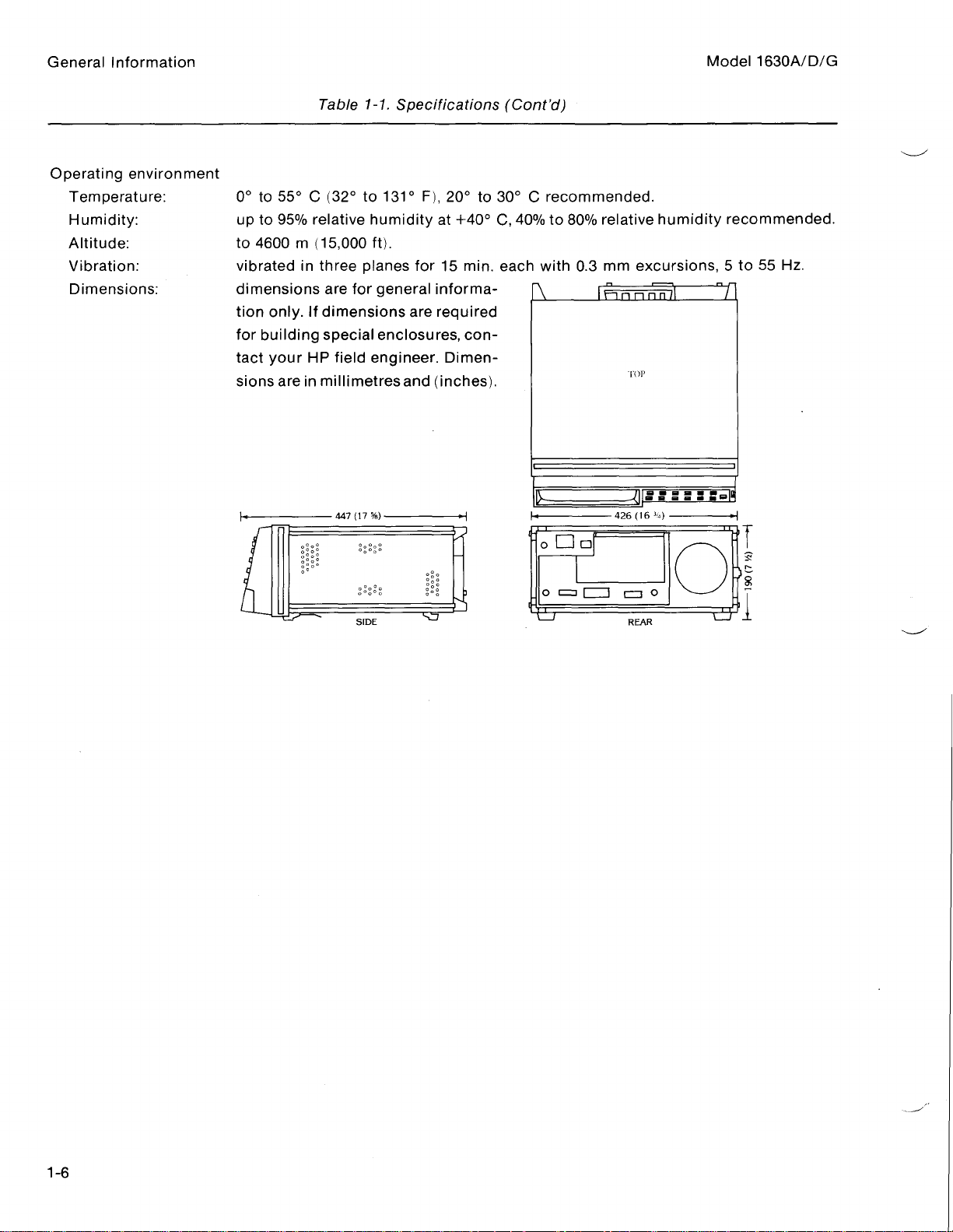
Operating
Temperature
Humidity
Altitude
Vibration
Dimensions
environment
:
:
:
:
:
0°to55°C(32°to131°
up
to
t
o
4600
vibratedinthree
dimensions
tion
for
building
tact
sions
relative
95%
m
(15,000
only.If
your
dimensions
special
HP
areinmillimetresand
are
field
humidity
ft)
planes
for
general
enclosures,
engineer.Dimen-
.
F),
20°to30°Crecommended
at
+40°
C,
40%
for15min.each
informa-
are
required
con-
(inches)
.
to
with
80%
0
relative
mm
.3
.
humidity
excursions,5to55Hz
recommended
.
.
Page 17
Model
State
Clocks
Data
Resources
Trigger
Restart
Store
Occurrence
Compare
Arming
1630A/D/G
Mode
:
Indexing
:
:
qualifiers
:
General
Table
1-2.Operating
three
ORed
Clock
Different
the
multiplexed
:
:
:
:
four
terms
termisthe
oftenasdesired
uptofour
The
last
onetofour
condition
onetofour
separately
be
occurrence
trace
until
widthofthe
the
[Edit
trace
may
can
be
the
state
Analyzer
clocks
edge
is
edge
including
AND
resource
terminthe
resourceterms
.
resourceterms
of
compare
analyzer,
Compare]
be
compared.Eachwordinthe
compared
analyzer
.
operate
selectable
selections
mode
the
combination
.
terms
sequence
defined
the
last
"equal
mode.When
anywhere
can
.
Boolean
for
eventinthe
withadepth
be
Characteristics
in
single-phase
as
positive,
may
be
made
NOT
of
bit
patternsineach
may
beusedinsequence
may
useupto
may
be
used
may
be
usedinan
each
terminthe
sequence
to"or"not
upto16
the
1630G
in
the
1024
armed
by
the
two-phase
or
negative,
on
the
same
of
each
term,
four
resource
inanORed
ORed
trigger
may
equal
to"isprovided.The
wordsinthe
is in
the
compare
deep
memory
full
Data
demultiplexing
or
both
edges
clockifusedineach
ALL
patterns, or
label.)Terms
to
establish
condition
format.Store
sequence
be
specified
1630A/D
[Full
buffer
.
Indexing
the
termsinan
forasequence-restart
.
Compare]
can
have
capability of
upton=59999
compare
andinthe
Information
for
each
phase
NO
pattern
be
parameter
ORed
fileisthe
cares"
the
used
format
1630G
an
Timing
may
trace
qualification
mode,
"don't
mode
clock
.
may
entire
and
.
.
of
(A
as
.
.
.
in
Overview
XY
Time
State
Time
measurement
Linkage
measurement
Chart
:
measurement
histogram
position
a
chartofany
lower
bounds
displayed
:a
timer
with
restart
stopped
histogram
to
eight
time,
and
Resolution-displayed
digit
display).Histogram
:
:
:
a
histogramofany
labels
Maximum
producesatime-varying
occurrences
behavior
the
histogram
then be
Resolution-actual
and
relative
user-defined
of
the
chart,
.
can
be
started
and
occurrence
and/or
time
of
made
restarted
of
the
start/stop
ranges.Minimum
total
samples
user-defined
ranges
Count-approx
for
.
ofanevent
systems
frequency
identificationoflightorheavy
to
optimize
countisrounded
label
and
on
completion
on
time
are
also
statistics
ranges:1
2(E63)
profileofsystem
per
under
time-varyingloads
direct
of
program
canbeshown.The
all
1024
states of
asequence
of
capability
OR'd
measurement
time,
displayed
250nsor0.1%ofreading,
label
unit
time.The
transfers
like
combinations
maximum
usec
.
canbeshown.The
.
efficiency
to0.1%
the
state
is
displayed.The
time,
.
activity.Measurements
measurement
.
between
transfer.Modificationsofsoftware
.
(4-digit
user
can
change
memory
ofupto
dataindexing.The
of
one
module
canbesimultaneously
threeresource
to
four
resource
user
average
user
display)
time,
whicheverisgreater,
can
specify
are
is
usedtounderstand
pairs
are
.
the
upperand
timer
can
specify
last
time,
uptoeight
the
number
depicted
terms
can
terms
be
.
up
total
(4-
of
the
in
may
A
a
Page 18
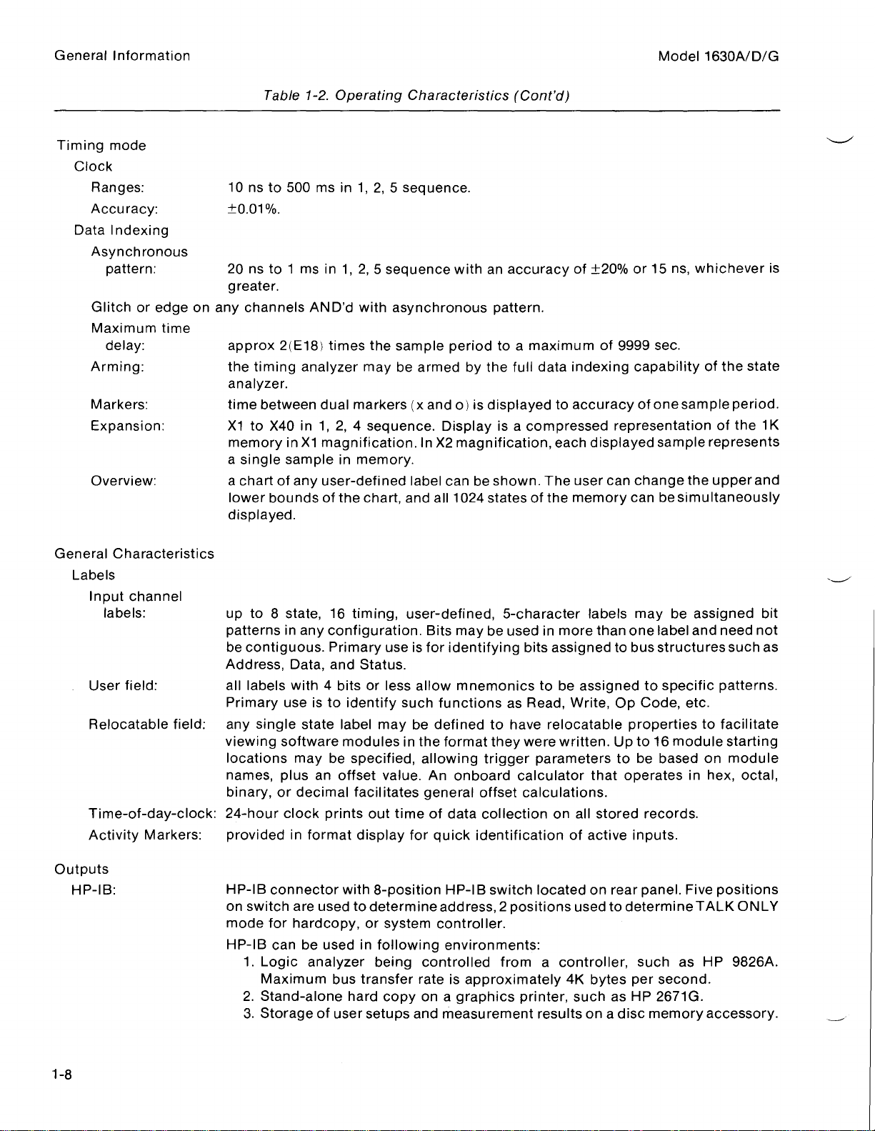
General
Timing
Clock
Data
Information
mode
Ranges
Accuracy
Asynchronous
Glitch
Maximum
Arming
Markers
Expansion
Overview
:
Indexing
pattern
or
delay
:
:
edge
:
:
:
:
time
:
on
10 ns to
±0
.01%
20 nsto1
greater
any
channels
approx
the timing
analyzer
time
X1
to
memory
a
single
a
chartofany
lower
displayed
Table
1-2.Operating
500
ms
in1,2,5sequence
.
ms
in 1,2,5
.
AND'd
2(E18)
analyzer
.
between
in1,2,
X40
inX1magnification.InX2magnification,
sample
bounds
.
with
times
may
dual
markers
4
in
memory
user-defined
of
the
chart,
Characteristics
.
sequence
asynchronous
the
sample
be
sequence.Displayisa
label
and
withanaccuracy
period
armed
(x
.
by
ando)is
canbeshown.The
all
1024
(Cont'd)
of
±20%
pattern
to
the
displayedtoaccuracy
states of
.
maximum
a
full
data
compressed
the
indexing
each
user
memory
of
displayed
can
Model
or15ns,
9999
sec
capabilityofthe
one
of
representation
sample
change
canbesimultaneously
1630A/D/G
whichever
.
sample
the
of
represents
upper
state
period
the
and
is
.
1K
General
Outputs
Characteristics
Labels
Input
labels
User
Relocatable
Time-of-day-clock
Activity
HP-IB
:
channel
:
field
Markers
:
field
:any
:
:provided
up
to8state,
patternsinany
contiguous.Primary
be
Address,
all
labels
Primary
viewing
locations
names,
binary, or
24-hour
HP-IB
on
mode
HP-113
useisto
single state
software
plus
clock
connector
switchare
for
can
1.Logic
Maximum
2.Stand-alone
3.Storageofusersetups
16 timing,
configuration.Bits
Data,
and
with4bits
identify
label
modules
may
be
specified,
an
offset
decimal
in
format
hardcopy,
be
analyzer
facilitates
prints
with
usedtodetermine
used
bus
hard
use
Status
or
less
may
value.An
out
display
8-position
or
system
in
following
being
transfer
copy
user-defined,
may
be
is
for
identifying
.
allow
mnemonics
such
functions
be
defined
the
in
formatthey
allowing
general
timeofdata
for
quick
controller
controlled
rateisapproximately
onagraphics
and
trigger
onboard
offset
collection
identification
HP-113
address,2positions
environments
measurement
5-character
usedinmore
bits
as
Read,
to
have
were
calculator
calculations
switch
.
from
printer,
labels
than
assigned
tobeassigned
Write,
relocatable
written.Up
parameters
that
.
on
all
stored
of active
located
:
a
controller,
4K
resultsona
rear
on
usedtodetermine
bytes
such
as
may
be
assigned
one
label
and
need
bus
structures
to
specific
to
Code,
Op
propertiestofacilitate
to16module
to
bebasedon
operates
records
inputs
.
panel.Five
such
as
per
second
HP
2671G
disc
memory
etc
.
in
hex,
.
TALK
HP
.
.
accessory
such
patterns
starting
module
octal,
positions
ONLY
9826A
bit
not
as
.
.
.
Page 19
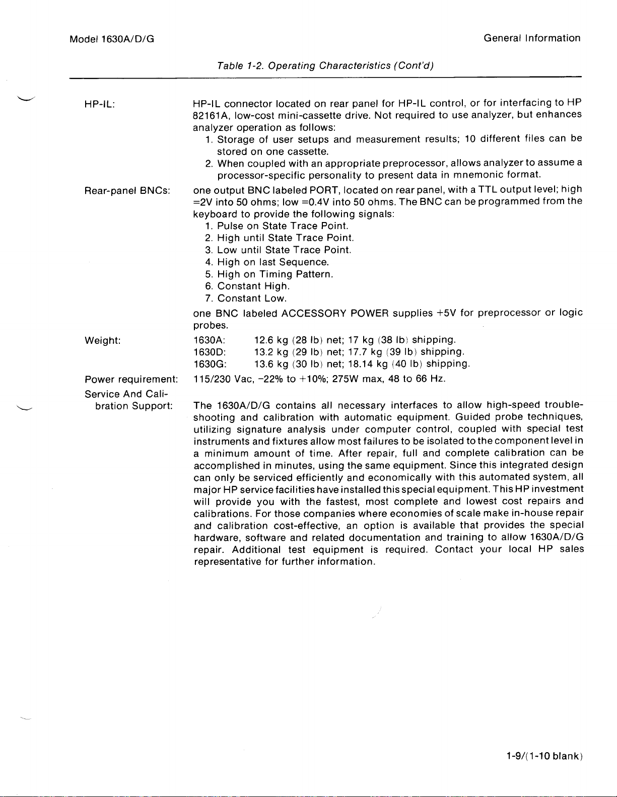
Model
HP-IL
Rear-panel
Weight
Power
Service
1630A/D/G
:
:
requirement
bration
And
Support
BNCs
Cali-
Table
HP-IL
82161A,
analyzer
1.Storage
stored
2.When
processor-specificpersonalitytopresent
:
one
output
=2V
into50ohms;low=0.4V
keyboard
1.Pulse
2.High
3.Low
4.High
5.High
6.Constant
7.Constant
one
BNC
probes
1630A
1630D
1630G
:115/230
The
:
1630A/D/G
shooting
utilizing
instruments
a
minimum
accomplished
can
only
major
will
provide
calibrations.For
and
calibration
hardware,
repair.Additional
representative
1-2.Operating
connector
low-cost
operation
on
coupled
BNC
to
provide
on
until
until
on
on
labeled
.
:
:
:
Vac,
and
signature
be
HP
service
12.6kg
13.2kg
13.6kg
and
amount
serviced
software
located
mini-cassette
of
user
one
labeled
State
State
State
last
Sequence
Timing
High
Low
ACCESSORY
-22%
contains
calibration with
fixtures
in
minutes,
facilities
you
with
those
cost-effective,
for
further
on
as
follows
setups
cassette
withanappropriatepreprocessor,
PORT,
the
following
Trace
Trace
Trace
Pattern
.
.
(28
lb)
(29
lb)
(30
lb)
to
+10%;275W
analysis
allow
of
time.After
efficiently
have
the
companieswhereeconomies
and
related
equipment
test
Characteristics
panel
rear
drive.Not
:
and
measurement
.
located
into50ohms.The
signals
Point
.
.
Point
Point
.
.
.
POWER
net;17
net;17.7kg
net;18.14kg(40
all
under
using
fastest,
information
kg
max,
necessary
automatic
computer
most
failurestobe
repair,
the
same
and
economically
installed
most
an
option
documentation
is
.
(38
(Cont'd)
for
HP-IL
control,orfor
required
on
rear panel,
:
supplies
lb)
(39
lb)
48to66
interfaces to
equipment.Guided
full
equipment.Since
this
special
complete
is
required.Contact
to
results;10
datainmnemonic
with
BNC
can
+5V
shipping
shipping
lb)
shipping
Hz
.
control,
isolated
complete
and
with
equipment.This
and
of
available
and
trainingtoallow
use
allows
be
for
.
.
.
allow
coupled
to
this
lowest
scale
that
General
analyzer,
different
analyzertoassume
TTL
a
programmed
preprocessor
high-speed
the
component
calibration
this
automated
make
provides
your
Information
interfacingtoHP
but
files
format
output
probe
techniques,
with
special
integrated
HP
cost
repairs
in-house
the
1630A/D/G
local
enhances
can
.
level;high
from
the
or
logic
trouble-
test
level
can
design
system,
investment
and
repair
special
HP
sales
be
a
in
be
all
1-9/(1-10
blank)
Page 20
Chapter2.Installation
Introduction
Initial
Inspection.. . . . . . . ...
Power
Line
AC
Operator's
Site
Rear
Rear
Connecting
Applying
Self-Test
Connecting
Requirements
Voltage
Power
Selection.. . . . . . . . . . . .
Panel
PanelBNC
1630A/D
1630G
Connecting
Connecting
. . . . . . . . . . . . . ...
Selection
Cable. . . . . ... . . .
Maintenance. . . . ... .
Address
Connectors.
Operating
Operating
. . . . . . . . . . . . . . . . . . .
Self-Test
Self-Test
Analyzer
Analyzer
Probes
. . . . . . ... . . . . . . . . . . .
. . . . . . . ... . . . . . . . . . ...
. . . . . .
. . . . . . . . ... . . . . . . . . . ...
. . . . . .
. ..... . . . . . . . . . . . . . . . . .
. . . . . . . . . . . . . . ... . . . . . .
. . . ... . . . . ... . . ... ...
. . ... . . . ... . . . . . . . . . . . . . .
Switch.
Power
Power
. . . . . . ..... ..... . . ..... ...
. . . . . . . . . . ... . . ... . . . .
To
Through
DirectlyToTarget
. ..... . . . . . . . . ... . . . . . . .
. ... . . . . . . . . .
.
. .
. . . . . . . . . .
. .
. .
.
.
. . . . . ... . .
. .
. .
Target
. . . ...
System.
Probe
.
.
.
. .
. .
Interface
System
. . . . . . . .
. . . . . .
. . . . . . .
. . . . . ... . . . . . . . . . . . . . ... . . . . . .
. . . . . . ... ...
. . . . ... . . ... . . . . . .
. . . . . . . . . ..... . . . . ...
. . . . . . . . . . . ... . . . .
. .
. . . . . . . .
. .
. . . . . . . .
. .
. . . . . . . . .
. ... . . ... . . . ...
. . . .
. . .....
. . . . . ... . . . . . . . . . . .
. . . . . . . . . . . . . . . . .
.
. . . . . . .
. . ... . .
. . . . . . . . . . . . . . .
. .
. . . . ... .
. . . . . . ... .
. . . . . .
. . .
. . . . . . . . . . . . . . .
. . . ...
. . . . .....
. .
. ... . . .
. . .
. ..... . .
. . . . . . . . . . . . .
. . . ... . . . .
. . . .......
. . . ...
. .
. . .
. . . . . .
. .
. . . . . . .
. . . . . . .
. . . . . . . .
. . .
. .
. . ...
. . . . .
. . . .
. . . .
. . .
. . . .
. . . . .
. . .
. . . . .
. . . . .
. . . . .
. . . . . .
...
. . . . . .
.
. . . . . .
...
. . .
. . . . . .
. . ...
. . . . .
. . ..2-2
. .
. .
. . . . .
. . .
. . . . . .
. . . . . . ..2-3
. . . . .
. . .
. . . . . . .
. . . . . .
. . .
. . ...
. . . .
. . . .
. . . .
. . . . . ..2-6
. .
. .
. .
2-1
2-1
2-1
2-2
2-2
2-2
2-2
.
2-3
.
2-3
2-4
2-4
2-4
2-6
2-6
Page 21
Model
1630A/D/G
INTRODUCTION
of
The
purpose
measurements
self-test
the
INITIAL
this
inasystem
are
INSPECTION
avoid
To
shipping
of
panels)
chapteristo
also
described
hazardous
damage
.
under
electrical
describe
test.The
.
to
any
how
the
self testofthe
WARNING
shock,
portionofthe
do
analyzerissetupand
not
outer
analyzer
perform
enclosures
and
electrical
of
the
messages
tests
the
instrument
probe
that
when
Installation
Chapter
Installation
cablesare
may
there
(covers
be
displayed
are
signs
connected
during
and
2
for
Inspect
should
contents
test,
cushioning
shipping
be
notify
POWER
The
1630A/D/G
to66Hz;275
48
until
nearest
for
container
the
contents
Hewlett-Packard
show
inspection
the
shipping
kept
are
incomplete,ifthereismechanical
your
materials
materials
for
signsofstress,
REQUIREMENTS
LogicAnalyzer
watts
isaSafety
This
uninterruptible
product
likely
and
If
this
sure
input
that
be
secured
instrument
the
common
the
maximum
wiring
protection
requires
ClassIproduct
safety
earth
terminals,
against
istobe
terminalisconnected
damage.If
of
the
shipment
Sales
by
power
carrier
the
a
.
groundmust
has
been
any
unintended
energized
the
shipping
havebeen
or defect, orifthe
Service
carrieraswellasthe
of either
notify
power
damage
and
the
.
source
WARNING
(provided
be
provided
power
cord,orsupplied
impaired,
viaanautotransformer
the
operation
to
the
container
inspected
Office.If
115
with
a
from
instrument
.
earthed
cushioning
or
mechanically
the
shipping
or
230
protective
the
main
power
poleofthe
must
for
cord
voltage
material
and
instrument
Hewlett-Packard
Vac
-22%
earth
power
set.Whenever
be
power
does
containerisdamaged,
to
terminal).An
sourcetothe
made
inoperative
reduction,
source
is
damaged,
electrically.If
not
pass
office.Keep
+10%;single
it
is
make
.
the
or
phase,
it
the
self
the
the
Page 22

Installation
LINE
AC
VOLTAGE
BEFORE
voltage
If
and
can
POWER
BEFORE
instrument
The
contact.The
(power
a
SELECTION
CONNECTING
switchisset
the
line
fuse
repairedbya
cause
additional
CABLE
CONNECTING
must
Mains
two conductor
plug
cable)
correctly
burns
out,donot
qualified
damage
be
connected
must
protective
without a
outlet
THIS
and
service
.
THIS
be
insertedina
action
protective
does
not
INSTRUMENT
that
the
proper
replaceituntil
person.Replacing
WARNING
INSTRUMENT,
to
the
protective
socket
must
not be
conductor
provide
an instrument
to
line
(Mains)
fuseisinstalled
the
cause
this
the
protective
conductor
outlet
negated
(grounding).Grounding
provided
by
voltage,besure
for
failure
fuseina
earth
the (Mains)
of
withaprotective
the useofan
ground
.
.
has
been
damaged
terminalofthe
power
extension
conductor
one
Model
the
line
determined
instrument
cord
earth
cord
1630A/D/G
.
of
OPERATOR'S
The
the
are
be
SITE
Place
instrument
only
front
panel
used.Useamild
damaged
.
Use
circuitry
Do
this
kelite,
SELECTION
the
logic
MAINTENANCE
maintenance
keyboard.When
soap
care
when
it
seeps
if
not
use
chemical
instrument
parts
20
analyzerona
an
cleaning
and
water
cleaning
under
cleaning
.
Recommended
water),ora
clean
operator
solution.If
the
the
solutionof1%
workspace
needstoperformisto
the
1630A/D/G,
front
keys
.
agents
cleaning
caution
a harsh
panel
or
which
soaporsolvent
CAUTION
keyboard.Water
abrasive cleaners
agents
mild
detergent
has
are
isopropyl
adequate
occasionally
must
be
used
is
used,
can
damage
that
may
damage
alcohol,
and
99%
ventilation
clean
with
the
water-base
water
.
the
display
which
the
the
kelite(1part
.
cleaning
paint
keyboard
plastics
screen
finish
in
and
agents
will
REAR
The
for
switches
setto"1".The
buses
2-2
PANEL
dip
(dual-inline-package)
operationonthe
set
.
the
address
positions
ADDRESS
HP-IB
and/or
the
of
switches7andSdeterminethe
of
SWITCH
switchonthe
HP-IL
analyzer
interface
for
rear
HP-113
panelofthe
buses,
operation.Switch
logic
andtoexecute
analyzer
analyzerisusedtoconfigure
analyzer
the
the HP-I
routine.The
B/HP-ILinterface
the
six
executes
configuration
self-test
on
the
analyzer
first
self-test
five
when
Page 23
Model
REAR
The
external
The
SYSTEM
1630A/D/G
1.When
address
2.If
operating
external
3.Set
switch
A
down
PANEL
rear-panel
HP
rear-panel
[Peripherals]
CONNECTING
operating
for
printer,
switchissetto"1"
.
BNC
preprocessor
BNC
the
analyzeraspart of
your
analyzer.Set switches
the
analyzer
set
switches
sixto"0".Switch
BNC
labeled
labeled
CONNECTORS
ACCESSORY
interface
PORT
menu
OPERATING
in a
stand-alone (no
seven
sixissetto"1"
when
module
provides
for
controlofexternal
its
and
toggle
POWER
a system,
seven
eight
POWER
.
TTL
a
set
eight
and
external
to select
only during the
NOTE
leverisup,
provides 5
control
signal
measurement
switches
to select
controller)
the
TALK
self-test
and
setto"0"
volts(1ampere
whose
instruments
one
through
the
desired
configuration,
ONLY
mode
.
when
its
maximum)
characteristics
and
five
to select
system
with
(both
toggle
are
equipment
Installation
the
system
controller
or
switches
is
lever
operating
for
selectableinthe
.
without
to
.
"0")
an
.
an
APPLYING
Follow
these
Before
cords,
interrruptionofprotective
personal
Use
fusesorshort-circuited
Before
on
may
Excessive
rating
switching
auto-transformers,
injury
only
the
switching
the
rear
result
.
input
describedintable
the
or death
recommended
the
must
panel
voltage
instrument
.
fuseholders.To
instrument
be
will
OPERATING
steps before
applying
and
devices
earth
groundingisa
fuse
power
settothe
damage
1-1
.
POWER
line
power
WARNING
on,
connect
with
the
switchtotheonpositon,
voltage
the
to
the instrument
all
protective earth
toaprotective earth
potential
required
doso
could
power
input
source,ordamage
attenuators.Observe
shock
current
cause
.
grounded
hazard
rating.Do
severe
shock
the
terminals,
that
not
lineselection
to
the
extension
socket.Any
could
use
fire
or
instrument
the
maximum
result
in
repaired
hazard
switch
input
.
rear
On
Press
panel
1.Check
2.Pluginsupplied
front
panel
:
VOLTAGE
LINE
SELECTOR
power
to1(down
cable
switch
.
position)
for
.
correct
setting
.
2-3
Page 24

Installation
SELF-TEST
The
analyzer
ROM,
and
same
checks
The
self-test
errorisdisplayed
Sales
and
To
initiate
front
the
1630A/D
the
When
screen
has a
functioningofthe
and
provides
Service
Before
the
HP-113
the
self-test,
panel
Self-Test
self-testofthe
:
self
test
also
checks
troubleshooting
during
Office
initiating
cable
set
LINE
power,
routine
the
.
the
from
switch6oftheHP-1Baddress
1630A/D
containedinthe
measurement
HP-IB
the
informationifthe
self-test,orif
self-test,
the
off
and
rear
on,
has
disconnect
been
channels
port
and
the
self-test
panelofthe
and
the
analyzer
successfully
analyzer
within the
internal
analyzerisnot
does
NOTE
any
connected
analyzer
switch
completed,
ROM.The
analyzer.The
storage
not
automatically
occur,
.
the
on
.
functioninginthe
contact
pods
rear
the
self-testofthe
self-test
your
from
the
target
panelto"1"
executes
following
the
messages
1630A/D
the
of
normal
nearest
system
(switch
self-test
Model
1630A/D/G
checks
1630G
manner.If
Hewlett-Packard
and
lever
.
aredisplayed
makes
up)
RAM,
Cycle
.
the
an
on-
PV
Reset
If
the
Acq
1630G
When
Tests
Pass
Rear
self-test
ErrorinRAM
ErrorinROM
nn
has
error
nn
Self-Test
the
self-test
RAM
ok
ROM
ok
Acquisition
Internal
HP-113
storage
ok
Panel
Switch
not
been
Expected
#n
nn nn nn nn
nn
the
1630G
of
ok
ok
XXXX
to
successful,
XX
was
has
been
XOXX
to
continue
oneormore
YY
successfully
of
following
the
completed,
the
following
messages
will
appear
messages
on-screen
appear
:
on-screen
:
Toggle
Reset
HP-113
rear
address
panel
MSB
switches
to
to
XXXX
reset
internal
XOXX
storage
to
continue
Page 25
Model
1630A/D/G
Installation
Ifanerror
following
RESETTING
When
resets
displayed
screen.If
displayed
To
manually
internal
successfully,
the
without
information
internal
more
loaded
messages
ErrorinRAM
Error
Acq
error
nn
Internal
HP-1113
an
error
internal
on-screen.If
.
storage"
message
the
storage
information
to
the
occurs
in
nn nn nn nn
failed
the
internal
to
ROM
:
checksum
INTERNAL
detected
is
storage
reset
reset
will
the
message
"Reset
the
and
about
analyzer
in
RAM
may
#(0-7)
loopback
.
the
has
internal
appear
failed,
storage
internal
the
without
or
ROM,
appear
Expected
error
test
STORAGE
in
the
While
resetissuccessful,
not
been
storage,
on-screen
"Internal
internal
and
storage
message
internal
the
in
placeofany
XX
nn nn nn nn nn
checksum
resetting
successful,
toggle
storage
storage
the
performance
via
"Internal
storage
internal
self-testisdiscontinued.When
one
or
more
of
the
was
XY
of
internal
the
switch
while
reset
has
the
SYSTEM
storage
and
the
storage
internal
the
storage
storage,
message
the
message
1ofthe
resetistaking
successful"isdisplayed.If
failed"isdisplayed
of
the
[Peripherals]
failed
SYSTEM
.
during
message
the
"Internal
"Reset
HP-1113
address
place.When
analyzerisnot
power-up"
[Peripherals]
is
not
the
self-test
previous
the
"WAIT
storage
failed,
switch.The
on-screen.The
menu,
willbedisplayed.RefertoChapter
menu.Inverse
messages
self-test,
reset
the
affected.When
the
the
Resetting
successful"
internal
message
the
reset
reset
analyzer
analyzer
storage
has
analyzer
assemblers
successful,
:
automatically
internal
displayed
is
has
"WAIT
has
beencompleted
not
been
may
attempting
will
attempt
successful,
storage"
failed"
Resetting
be
to
to
may
not
the
on-
used
store
reset
8
for
be
is
is
POWER
When
the
Self-Test
During
accessories
does
upsequence
first,
loaded"
correct.Ifonpower-up,
diplayedinthe
"Internal
failure"
lost"
UP
DISPLAY
the
analyzerispowered-up,
SYSTEM
not
and
will
[Configuration]
switch
Reconnect
switch6to
the
take
then
willbedisplayedinthe
storage
willbedisplayed.Ifaninverse
be
on
the
power-up
that
may
place.Inverse
unless
displayed
instructed
the
stored configurations.The
lower
reset
MESSAGES
HP-1113
HP-IB
"0"
routine,
be
left
accessory
.
connected
assemblers
the
internal
hand
successful"
whether
it
menu.The
address
the
analyzer
otherwiseinthe
lower
cornerofthe
the
goes
to
the
left
storage
if it
was
assembler
internal
through
same
switch
instruments
and
hand
a
sequence
power-up
has
been
NOTE
to rear
reads
the
HP-1113
HP-1113
abletoreset.When
port.Addresses
storedconfigurationsare
SYSTEM
messages
cornerofthe
checksum
display.The
was
storeditwillbelost
storage
failedorwas
of
routines
returned
panel
port
[Peripherals]
"Inverse
display
isinerror,
analyzer
not
power-up
are
performed
to "0"
HP-1113
and
abletoreset,
port
automatically
are
assigned
automatically
menu
assembler
when
the
message
will
reset
and
successfully
routines
(switch
before
The
.
the
the
the
and
displays
after
the
lever
down)
setting
assigns
duplicationofaddresses
so
re-loadedinthe
inverse
loaded"
internal
"Internal
internal
the
message
reset
assemblerisloaded
and
storage
storage
message
.
messages
self-test
.
HP-1113
addresses
"Configuration
storage
"Internal
"Inverse
when
power-
checksum
corrupt"
and
display
storage
assembler
to
on
the
any
is
is
2-5
Page 26
Installation
CONNECTING
The
analyzer
connections
will
differ,
depending
the following
Connecting
1
.
Install
2.Connect
microprocessorinthe
3.Connect
to
the
4.Connect
ACCESSORY
can
collect
from
the
paragraphs
Analyzer
the
preprocessor
the
ribbon cable
the
probe
general
a
BNC
ANALYZERTO
information
general
upon
purpose
whichofthe
foradescriptionofhow
through
Through
interface
from
the
target
pods
purpose
cable
POWER
system
from
the
preprocessor
from
the
(+5V)
BNC
TARGET
eitherHPModel
probes.The
two
typesofconnections
procedurestobe
to
Probe
module
probe
analyzertothe
ACCESSORY
connector
in
interface
.
operating
the
NOTE
SYSTEM
make
the
Interface
probe
appropriate
note
on
(with
POWER
the
for
probe
interface
preprocessor
10269A/B
followed
are
made.Refertothe
connections
.
pod
socketsonthe
appropriate
BNC
on
interface
Probe
Interfaceorthrough
when
making
for
your
interface
connections
pod
the analyzer
.
Model
the
procedures
particular
module
probe
rear
1630A/D/G
direct
connections
given
in
equipment
installed)tothe
interface.Refer
.
panel
to
the
.
Some
cable,HPrecommends
voltage
Connecting
1.Snap
2.Connect
3.Connect
on
unconnected.Do
example)inthe
interface
drop
Probes
the
adapters
the
line
the
ground
modules
.
for
not
same
can
using4feet,
Directly
for
eachofthe
each
probe
connect
probe
probe
pod
from each
drawupto1
To
general
bittomonitoranode
signals
.
ampere
maximum,
Target
with
different
podtoa
purposeprobe
from
of
System
threshold
ground
the
type
RG-58
in
the
pointinthe
5-volt
coaxial
pods
system
levels
supply.If
cabletominimize
.
under
(some
system
using
test.Leave
TTL
and
under
coaxial
some
test
.
extra
ECL,
lines
for
Page 27

Chapter3.Front
Introduction
State
Timing
Interactive
Panel
Measurements
Controls
. . ... . ... . . . . . . . . . . .
Measurements
State/Timing
and
Menu
. . . . . . . . . . .
. . . . . . . . . ... . . . . . . . . . . . . . . . ...
Measurements
Map
. . .
. . ..... . . . . . . . .
. .
. . . . . . . . . . . . . . .
. . . . . . . . . . . . . . .
. . . . .
. . . . . .
. . .
. . . . . . .
. . . . .
. . . . .
. . . ... .
. . . .
. . . . .
. . . .
. . . .
. . . . .
. . . . .
. . . . .
. . . . .
. . . . . . . .
. . . . . . . .
. . . . . .
. . . .
. . . . .
. ... .
. .
. .
3-1
3-1
3-1
3-1
Page 28
and
Menu
Model
1630A/D/G
Front
Panel Controls
Map
INTRODUCTION
This chapter
Analyzers.Figure
Figure2isamap
front
the
accomplished
State
Start
"
Configure
"
FORMAT
"
Specify
"
consistsoftwo
panel
keyboard.In
by
Measurements
with
the
the
the
1 is
of
the
for
TRACE
figurestohelp
the
front
panel
the
available
following
SYSTEM
state
analysisbyselecting
input
databyassigning
tobecollectedbythe
menus
general,
steps
Specification
Front
keyboardofthe
by
selection
making
:
state,
[Configuration]
labelstogroups
Panel
familiarize
timingorinteractive
all
channels
state
Controls
the
1630.The
with
the
menu
analyzer.(press
user with
functionofeach
INPUT
for
of
the operation
or
OUTPUT
state
(power-up
.
state
measurements.(use
probe
bits.(press
and
TRACE)
and
key
DISPLAYS
timing
or
press
Chapter
Menu
the
of
is
FORMAT)
1630A/D/G
describedinthefigure
keysatthe
measurements
SYSTEM)
ROLL
Map
keys)
Logic
top
maybe
3
.
of
Timing
"
"
"
"
Measurements
Start
with
Configure
FORMAT
Specify
the
Interactive
"
"
"
"
Chapters
with
Start
Configure
FORMAT
Specify the
4
through
the
for
the
SYSTEM
timing
input
TRACE
Specification
analysisbyselecting
databyassigning
tobecollectedbythe
State/Timing
the
SYSTEM
for
interactive
the
input
TRACE
8 contain
Specification
databyassigning
tobecollected
Measurements
measurements
by
step-by-step
[Configuration]
timing
labels.(press
timing
[Configuration]
by
labelstoboth
the
timing
procedures
channels
analyzer.(press
selectingacombination
and
for
menu.(power-up
and
glitch
FORMAT)
menu.(power-up
and
state
the
setting
timing
state
analyzers.(toggle
the
up
or
press
mode
TRACE)
or
press
state
of
pods.(toggle
specific
SYSTEM)
(onoroff)
SYSTEM)
and
timing
FORMAT)
TRACE)
menus
.
.
channels
.
Page 29
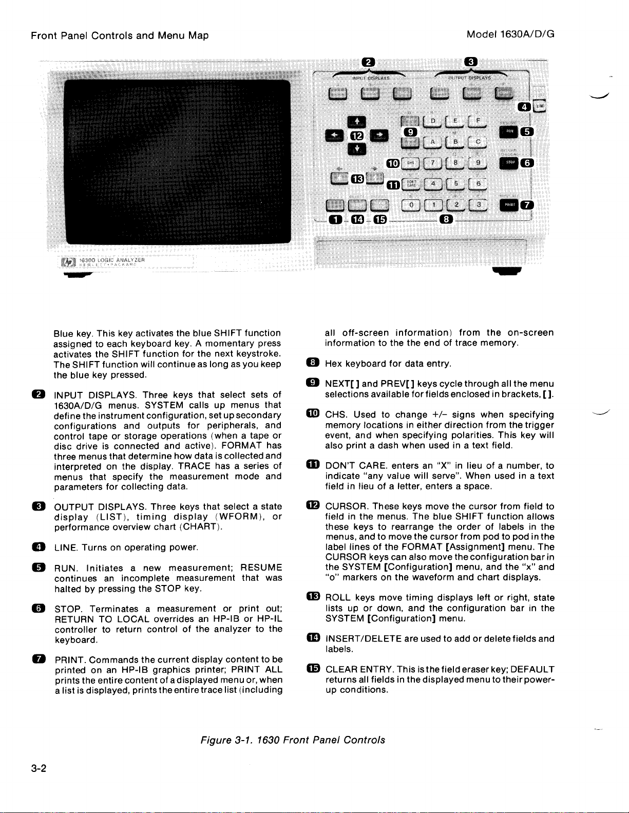
FrontPanel
Blue
assignedtoeach
activates
The
the
©
INPUTDISPLAYS.Three
1630A/D/G
define
configurations
control
disc
three
interpreted
menus
parameters
Controls
key.This
the
SHIFT
function
blue
key
menus.SYSTEM
the
instrument
tape or storage
driveisconnected
menus
that
on
that
for
and
key
activates
keyboard
SHIFT
pressed
and
determine
the
specify
collecting
Menu
Map
SHIFT
the
blue
A
momentary
key
.
function
will
.
configuration, setupsecondary
outputs
display.TRACE
the
for
the
continueaslongasyou
keys
that select sets of
calls
peripherals,
for
operations
and
how
measurement
data
(when
active).FORMAT
dataiscollected
.
function
next
keystroke
menus
up
a tape
hasaseries of
mode
press
keep
that
and
or
has
and
and
Model
all
off-screen information)
informationtothe the
.
0
Hex
43
m
m
keyboard
NEXT[]
selections
CHS.Used
memory
event,
and
also
printadash
DON'T
indicate
field
in lieuofa
for
and
PREV[]
available for
to
locationsineither
when
CARE
.
enters
"any
value
endoftrace
data entry
keys
fields
change
specifying
when
an
will
letter,
entersaspace
from
.
cycle
through
enclosedinbrackets,[]
+/-
signs
direction
polarities.This
usedina
"X"inlieu
serve".When
memory
when
text
1630A/D/G
the
on-screen
all
specifying
from
the
field
number,
of
a
usedina
.
.
the
.
menu
trigger
key
will
text
.
to
OUTPUT
©
display
performance
LINE
©
RUN.Initiates
continues
halted
STOP
RETURN
controller
keyboard
PRINT.Commands
printed
prints
a
list is
3-2
DISPLAYS.Three
(LIST),
Turnsonoperating
.
an
pressing
by
.
Terminates
TO
to return
.
on an
the
entire
displayed,
timing
overview
a
incomplete
the
LOCAL
the
HP-113
contentofa
prints
new
a
controlofthe analyzertothe
keys
that
display
chart
(CHART)
power
measurement
measurement
STOP
key
measurement
overridesanHP-113orHP-IL
current
graphics
the
display
displayed
entire
select
(WFORM),
.
.
.
or
contenttobe
printer;PRINT
menu
trace
list
Figure
state
a
;
RESUME
that
was
print
out
ALL
or,
when
(including
3-1.1630 Front
or
©
CURSOR.These
fieldinthe
these
keystorearrange
menus,
label linesofthe
CURSOR
the
"o"
©
ROLL
;
listsupor
SYSTEM
m
INSERT/DELETE
labels
©
CLEARENTRY.Thisisthe
returns
up
Panel
andtomove
keys
SYSTEM
markersonthe
keys
[Configuration]
.
all
fieldsinthedisplayed
conditions
Controls
keys
move
menus.The
the
cursor
FORMAT
can
also
[Configuration]
move
down,
.
move
waveform
timing
and
the
are
usedtoaddordelete
the
cursor
blue
SHIFT
the
[Assignment]
the
displays
configuration
menu
field
function
orderoflabelsinthe
from
podtopodinthe
configuration
menu,
and
and
chart
leftorright,
.
eraser
key;DEFAULT
menutotheir
from
field
menu.The
the "x"
displays
barinthe
fields
power-
to
allows
bar
and
.
state
and
in
Page 30
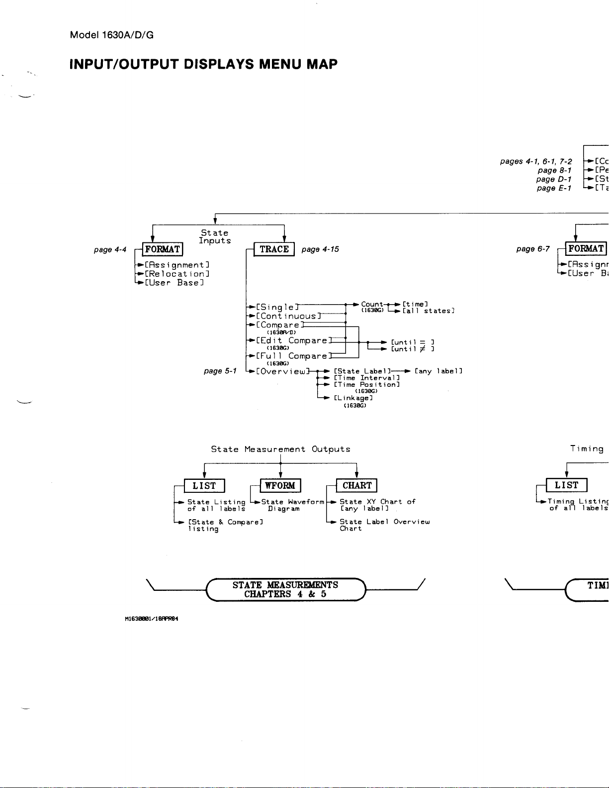
Model
1630A/D/G
INPUT/OUTPUT
4-4
page
DISPLAYS
MENU
[Single
[Continuous
[Compare
(1638fVD)
[Edit
[Full
[Overview
(
.6386)
(I630G)
Compare
Compare
MAP
[State
[Time
[Time
(16306)
[Linkage]
(16386)
Count-t-o-Ctime]
(16306)
y
Cal
Cunt
Cunti1
Label]-i
Interval]
Position]
l
1=]
i
[any
states]
]
label]
pages
4-1,
6-1,
page
page
page
7-2
8-1
D-1
E-1
[Assign
[User
H
M1630001i18fFR81
State
StateListing
of
all
labels
MeasurementOutputs
4w-State
STATE
CHAPTERS
Waveform
Diagram
MEASUREMENTS
4&5
CHART
State
Cany
label]
Oy
Timing
XY
Chart
of
Timing
Listin
of
all
labels
Page 31

SYSTEM
GConf
igurations
Peripherals]
Storage
fTape
Options]
Operation]
Timing
Inputs
Inment
]
Base]
[
:[Continuous]
[Continuous]
~[Rssignment
[Relocation]
FrontPanel
]
CSinglei
CContinuous7
[Compare
(1630FiLD)
[Edit
(16306)
[Full
(16306)
~
Compare]
Compare]
-
Controls
Count-t-fItime]
(1630G)
s
and
Cunt
Cunti1
Menu
[al
i 1
l
states3
=]
Map
3
q
Measurement
1PFORM
IngLo-
Timing
is
Waveform
KING
MEASUREMENTS
CHAPTERS
Diagram
6
Outputs
L-w-
[BART
Timing
of
Cany
XY
label]
Chart
State/TimingMeasurementOutputs
[Timing]
of
all
labels
Listing
Liw
Wave-Form
STATE/TIMING
CHAPTERS
[Timing]
MEASUREMENTS
Diagram
7
1-s
Timing
[any
Input/Output
XY
label3
Displays
Chart
of
Figure
Menu
3-3/(3-4
3-2
Map
blank)
.
Page 32

Chapter4.State
Introduction
CapturingAState
The
The
The
The
Inverse
The
Resource
Sequential
[Compare/EditCompare/Full
The
List
Waveform
XY
Charts
Measurements
. . . . . . . . . . . . . .
Trace
State
Format
State
State
State
Assemblers
State
Trace
Triggering
State
Display. ..... .
Displays.. . . . . . . . . . . . . . . . . . .
Of
Specification
[Assignment]
[Relocation]
[User
Base]
For
Specification
Terms
Displays..
. . . . . . . . . . . . . . . . . . . . . . . . . . . ...
Label
Activity
. . . . . . . .
. .
. . ... . . . . . . . . . . . . . . . .
Format
Format
Format
The
Logic
. . . . . . . . . . . . . . . . ...
. . . . . . . . . . . . . . . . . . . . . . . . . . . .
. .
. . . . ... . . . . . . . . . . . . .
. .
. ...
. .
. ... . . . .
. .
. . . . ... . . .
. . . . ... . . . ... . . . . . . .
Specification
Specification
Specification
Analyzer.. .
Compare]
. . .
Trace
. .
. ...
. . . ... . . .
. .
. .
. . . . . . . . . . . ...
. . . . . .
.
. . . .
. . . . .
. . . . . .
. . . . . . .
Modes. . . ... . . . . . .
. .
. . . . . . . . . .
. . . . .
. . . . . . . .
. .
. . . ... . . . . . . .
.
. . . . . . .
. . . .
. . ...
. . .
. . . . . . . . . . . . ... .
. . . . . . . . ...
. . . . . .
. . . . . . . .
. . . . . .
. .
. . . . . . . . . . . . ... . . . . . . .
. . . . . . . . . . . . . . . . . . . . . .
. . . . . . . . . . . . . . .
. . .
. . . . . . . . .
.
. . . . . . . . . . .
.
. . . . .
. . .
. . .
. .
. .
. . . .
. . . . . . .
. . . . . . . .
. .
. . . .
. . . . . . . .
. . . . .
...
. . . . .
. . . ... . . .
. . . . . .
. . . . . . . . ...
. . . . . . . . .
. . . . . . .
. . . . .
. . . . .
. . . . ...
. . . . .
. . .
. . . . .
. . . . .
. . . .
. .
.
. . . .
. .
. . . . . . . .
. . . . .
. . . . . .
. .
. .
... . . . .
.
... . . . . . . ..4-33
. . . . .
. . ... .
. .
. .
. .
. .
. . .
.
. . . .
. . .4-10
...
. .4-13
. . . .4-15
4-15
. . .4-19
. . . .4-22
. . . . . .4-27
. . . . . .4-31
.4-31
.4-34
4-1
4-1
4-4
4-4
Page 33

Measurements
Model1630A/D/G
State
INTRODUCTION
The
1630A/D/G
incoming
with
connections
assigning
by
ASCII.Another
The
tracing
provideatrace
terms
The
which
data
needs
the
1630A/D/G
for
user
next stepinmaking
techniques
specification
may
be
specified
target
system
contains
Logic
Analyzers
tobeformattedinan
analyzers
the
address,
defined
typeofuser
are
used
an
8085
data,
labels
base
the
captured
for
used
menu
for
simple
throughout
microprocessor.All
are
capableofcapturing
arrangement
by
grouping
status,
for
may
recognizing
in
triggering,
and
conditions
be
assigned
data
usefulisto
and
which
this
resource
manual
traces
large
quantitiesofdata.To
thatiseasily
the
incoming
other
linesofinterest.Incoming
rather
in
edit
storing
terms
sequence
for
examples
shown
lines
than
the
which
relocatable
the
data
only
qualified
may
triggering,
in
the
State
and
provided
before
be
identified
sequence
is
the
figures
Measurements
comprehensible
labeling
code
itisstoredbythe
data.The
HP
Model
are
bases
for
from
the
data
is
1630A/D/G
selective
restart,
5036A
Chapter
make
this
data
Thisisaccomplished
.
groups
may
hexidecimal,
of
labeled
and
the
for
further
be
by
the
analyzer
Logic
tracing.Resource
store
Microprocessor
5036A
.
useful,
the
typical
identified
binary,
user
.
.
Selective
Analyzers
qualifying
4
the
or
.
Lab
CAPTURING
1.Make
or
through
2.Apply
The
logic
configuration.The
storage
up
Display
default
measurements
1630G
display
up
Press
3
.
measurement
running.Figures
free-run
1630A/D
all
the
an
operating
When
target
analyzer
whenithas
Messages
system
The
1630A
.
messages
RUN.The
trace
because
A
STATE
required
ensures
with
connections
interface,isin
power
usingapreprocessor,
system
configuration
.
Figures
logic
4-2a
will
1630G
been
in
default
will
analyzer
and
the
it
has
the
to
the
may
execute
will
instructed
chapter2for
4-1a
System
appear
logic
4-2b
logic
more
TRACE
to
the
target
chapter2of
logic
analyzer
be
not run
and
will
are
analyzer.The
state
.
power-up
also
display
to load
more
assigns
4-1b
on
executeasingle
analyzerisconnected
examples
all
are
Specification
the
display
channels
system.Information
this
manual
andtothe
NOTE
sure
sequences
messages
internal
information
channels
the
default
of
the
State
andacounting
.
to
apply
indicating
configurationsoran
on
to state
System
menu
has
only
when
trace
and
to
state
traces
Listing for
target
and
system
power
to
display
the
power-upsequence
measurement
Specification
eight
less
the
analyzerispowered
display
the
target
that
the
1630G
function
for
connecting
.
analyzer
the
the
system
what
is
being
inverse
menus
channels
State
a
system
willbedisplayed
.
than
Listinginhexadecimal.The
and
has
more
the
probes,
firstorthe
menu
loaded
assembler.See
and
the
in
the
from
and
messages.The
none
for
the
the
1630D
up
.
target
collecting
when
columns
1630D
directly
default
internal
Power-
to
timing
Power-
.
system
than
and
is
a
the
Page 34

State
Measurements
Figure
System
Specification
I
Configuration
4-la.1630D
Specificatiori_____
System
------------
1
State
Channels Channels
35
27
Default
______ROLL
ROLL to
Timing
16
16
System
to
Change
Configuration-_--
8
Specification
change
configur,
.tion__
1
Menu
Model
1630A/D/G
Figure
L,""-
ser-.embler
Configuration
4-1b.1630G
State
Listing
Label>
Base
>
02028280000
+0000*
+0001*
0203838C100
+0002*
02028280200
+0003*
00009BE0100
+0004*
0000BBDDC00
+0005*
OOOOBBC0200
+0006*
0000BBB0100
OOOOBBA0200
+0008*
OOOOBB94400
+0009*
OOOOBB90200
+0010*
OOOOBB74-00
02028280000
+0011*
+0012*
02030398000
+0013*
02028280100
OOOODBE0100
+0014*
+001`*
0000BBDDC00
state
Channels Charnels
loaded
loan-led
Default
--------------------
A
T1,,ing
System
Data
Acquired
Specification
Oct271982
14
:44
Menu
I
4-
Figure
4-2a.Free-run
State
Trace
Captured
by
the
1630AID
2
Page 35

State
Model1630A/D/G
State
Listing
Label>
Base
+0000+0001"00000038
+0002
+0003
+0004*
+0085*
+0006*000000
®-
+0008*
+0009»+0010,
+0011+
+0012+
+0013*
+0014+.0004
+0015-+
A0 R1
>
00000037
00000039
0000003E
000
0
00000036
00000037
00000038
00000039
00000
0000
6001
_____________________-________________________
Time
04C043
0480431
0,48043900
0400436'00
04(-043700
04804
0,48043900
040043600
040043700
0480,43800
048043900
040043600
040:043700
0,48043800
0,48043900
040043600
.=800
0.0 s
2
.000
1
.480
1
.520
2
.000
2
.000us
1
.480
1
.520
2 .000us
22
.000 us
1
.480 us
1
.520 Ps
2
.000
2
.000
1
.520
1
.480
Ps
us
us
us
ias
us
ias
us
ias
Measurements
4.In
in
choices
number
number
return
the
afield
keyboard
Figure
The
figures
otherwise.Therefore,
State
enclosed
for
bases
base
the
different
function
Listing,
that
columns
panel
The
each
alternate
Use
than
.
the
in
brackets,[],
field
.
.
Each
time
and
all
columns
to
and
the
blue
shift
key.When
function/character.The
the
blue
4-2b.Free-run
in this
Use
the
manual
the
display
blinking
the
cursorisin
NEXT[]
oneofthe
are
original position,
ROLL
key
key
the
and
leftorright
enters
blue
the
State
Trace
NOTE
apply
directlytothe
when
of a
1630A/D.The
the
NEXT[]
and
two
illustrating
the
first
column
and
PREY[]
PREY[]
keystocycle
keysispressed,
shiftedtoaccommodate
press
the
key,asrequired
NOTE
the
alternate
keyispressed
blue
ROLL
keystomove
function/character
the
key
Capturedby
displayofthe
state
listings
1630A/D
of
the
keys
the
number
blue
shift
.
next
key
may
be
held
the
entire
the
1630G
the
does
not
field
nexttoBase.When
are
used
through
datainthe
bases
keyinthe
shown
pressed
down
display
1630G,
figures
unless
will
haveatime
to
select
theparameters
columnchanges
requiring
lower
will
for
repeated
area
left
in
blue
enter
left
more
and
titled
appear
tagging
available
characters
corner
above
the
blue
entries
right
the
cursor
parameter
available
to
the
of
theofthe
.
.
for
new
.
is
To
Use
the
blue
shift
keyand
cursoriswithinalabel
move
the
In
used
down
the
upper
to
keys
cursor
control
right
and
to
the
hand
the
display.The
the
ROLL
LABEL
field,
the
blue
first
positioninthe
cornerofthe
arrows
up
or
down
arrow
shift
NOTE
display,
keys
keystomove
key
and
next
fieldofthe
arrows
indicate
the
.
entire
arrow
an
indicate
CURSOR
labels
key
label
the
may
.
keys
left,
or,
when
be
that
right,
used
may
up, or
the
to
be
Page 36

State
Measurements
THE
The
State
The
logic
interprets
be
used
The
type
The
State
names
makes
Figures
1630G
label
channels
channels
channels
when
are
STATE
FORMAT
[Assignment]
analyzer
the
the
by
informationisspecifiedinthe
of
[Assignment]
(labels)tothe
the
data
4-3a
displayedinthe
from
are
not
The
assigned
must
acquire
data.Therefore,
logic
analyzer.The
groups.Assigning
displayed
and
4-3b
arethe
the
FORMAT
pods
5, 6,
initially
assigned
connected
arrowsatthe
the
to
Format
on
the
default
keyispressed.When
listing.All
and
are
indicated
left
leftoflabelAOand
SPECIFICATION
Format
data
from
the
clock
logic
Specification
logic
analyzer
State
channels
7 to
label
to a
labelsowhenatraceislisted,
byazero
and
rightofthe
Specification
the
target
assignments
analyzer
analyzer
labelstogroups
Format
"AO"
must
menu
much
Specification
the
on
the
and
channelsfrom
in
NOTE
label
to
the
systeminexactly
and
with
is
analyzer
1630A/D
the
fieldsinfigure
rightoflabelA1.
voltage
see
the
also
easier
State
thresholds
the
exact
State
[Assignment]
used
to
(such
as
for
the
menus
runsatrace,
are
defaulted
pods
all
Listing
4-3b
the
same
utilizedbythe
information
group
the
user
address,
to
that
incoming
are
only
to
1
through3to
channels
.
indicate
manner
that
Format
data
interpret
displayed
probe
label
"A".The
are
includedinthe
there
Model
as
the
system
the
target
Specification
channels
and
status
and
analyze
on
the
channels
label
"A1"
are
more
1630A/D/G
target
system
and
channels)
1630A/D
assigned
1630G
.
bits
system
must
sees
menu
assign
.
assigns
All
probe
listing
also
and
to
.
All
.
.
a
Format
State
Multiplexing
flctivity>
Label
Pol
Figure4-3a.1630AID
Specification
Pod4
8
. . . . . ..08
-----1111
Default
--------------------------------______
Pod3
. . . . . ..08
-1111112
111111111
State
. . . ...
Pod2 Podl
.0 7
. . . . .
IIIIIIII
Format
.0 7
Specification
PodO
. . . . .
_____I__
.0
Menu
Page 37

Model
CLOCK
The
1630A/D/G
ASSIGNMENTS
logic
analyzer
measurements
clock
assignment
specifications
the
NEXT[]
.
Three
specifiestothe
may
be
or
PREV[]
must
made
Figure
OR'ed
keys
State
Multi
Activity>
Label
4-3b.1630G
recognize
clocksare
by
moving
to
select
Format
Specification
lexPod?
®®®®®
____________________ __$IItISit
Pol
-----------------------------------_.
Pod6
Default
data
on
the
same
availableinthe
analyzer
to
the
cursortothe
different
collect
clocks
Clock
State
data
JKL
PodS
Format
clock
State
OR'ed
and
Pod4
____IS_IS
Specification
edge
as
[Assignment]
on
the
positive
clock
edges
.
Pod3
__1111111
the
target
Format
edge
fieldonthe
State
Menu
system
Specification.The
of
assignment
when
theJclock.Other
Measurements
taking
menu
and
state
default
clock
using
MULTIPLEX
Some
target
different
bits
the
move
multiplexed
are
data
the
times
and
cursortothe
Specification
the
number
holding
register
multiplexing
assignments,
and
edges
.
For
the
target
to
[27/38]
address
on
linesinthe
demultiplexing
THRESHOLD
Input
threshold
under
an
individual
determines
level
(if
below
the
ASSIGNMENT
systems
.Inthe
address
and
press
of
channels
and
on,
is
move
system
the
1630G.These
is
usually
ASSIGNMENTS
levels
whether
threshold
may
target
on
the
multiplexinginwhich
use
system
same
used
pinsofthe
willbelistedinseparate
field
the
under
NEXT[]
Multiplex (Multiplexing
or
PREV[]
tobeprocessed
master
the
edges
thecursortothe
usedinexamples
same
setat18
are
selectable
podand
the
level)
clock
for
the
are
manner
selecting
incoming
.
puts
master
clock
for
the
as
the
channels
for
TTL,
voltage
certain signal
for
the
examples
in
microprocessor.The
by
field
this
typical
each
columns
key.The
the
slave/master
both
and
slave
and
manual,
settings
8085.For
for
the
pod.The
in
the
multiplex
sets of
information
clock
use
the
the
multiplex
for
16-bit
slave
clock
thresholdisselected
ECL,orabsolutevoltages
willberecorded
lines
this
manual,
logic
analyzer
state
listing.To
on
1630
A/D)
choices
clocks.The
into
are
automatically
NEXT[]
or
PREV[]
fieldissetto[27/16]onthe
microprocessors
8-bit
microprocessors
instead
between-9
asalogic1(if
are
used
for
different
the
data
bits
and
demultiplexthese
can
the
State
clock
multiplexing
[Assignment]Format
moves
analyzer
set
in
the
displayedinratiosthat
are
slave
the
logic
assigned.To
keys
to select
that
that
utilize
27
.
of
bymoving
above
the
.9V
and+9.9V.The
the
threshold)
information
eight
lower
information
memory
change
different
1630A/D
multiplex
multiplexed
cursor
address
lines
mode
indicate
data
into
the
threshold
or a
.
When
clock
clocks
and
and
lines,
field
logic
on,
to
at
so
a
O
All
probe
connections
withinapod
NOTE
are
assigned
the
same
threshold
level
.
4-5
Page 38

State
Measurements
ACTIVITY
The
activity
which
single
LABEL
1.Move
2.Add
LINE
line
under
each
podinthe
voltage
bar
ASSIGNMENTS
will
field
characters.Up
(Labels
lineofthe
using
threshold
1
changes
indicatesasteady
the
cursor
appear
willbeadded.Labels are entered
are
the
label
the
voltageistobedisplayed
and
voltages
are taking
state,
AND
POLARITY
to
the
label
the
to
ADDR
below
display
eight
or
on
deletedbypressing
labeltobe
NEXT[]
deleted
to
the
PREV[]
are0.
screen
labels
State
place.A
either
columninthe
label
Choosing
double-ended
high
indicatinganew
may
be
blue
the
.)
column
+
key,
asa1or0.A+in
[Assignment]
low
.
or
State
with
numeric
assigned
shift
key
in
the
new
or -
may
-
gives
the
NOTE
Format
arrow
[Assignment]
label
keys
and
each
andand
field.Notice
be
selectedtoindicate
this
opposite
Specification
indicatesanactive
Format
be
may
and/or
label
DELETE
the
field
indicates
display
Specification
added.Press
the
may
when
fieldtothe
shift
blue
consist
the cursorisanywhere
whetheravoltage
voltages
.
Model
indicates the
channel(>400
menu.A
INSERT
key and
ofupto five
rightofthe
above
andanew
the
1630A/D/G
channels
Hz)
message
the
alphabetic
characters
field.By
label
above
threshold
and
label
on
on
a
.
the
the
are
3.Press
the
4.Press
in
the
designated
5.Press
the
and
hold
MSB
(most
Pod2
shifting
displays
either
entries
LIST
State
Listing.Figure
Polarity
the
CURSOR
significant
willbeoff-screeninthe
the
or
that
The
PREV[
Pod3
.
pods,orthe
are
4-4isthe
is
run,
format
of
.
NEXT[]
beneath
ADDR
.
.
The
bits
Whenatrace
or
not)
.
without
format
takinganew
menu
choice
right
bit)ofthe
]key
and
assigned
dataisacquiredonall
may
trace.Acquired
does
arrowtomove
address
1630G
blue
shift
be
.
to
The
the
times, or
listing
modified
sixteen
Pod2
state
asterisks
not
the
channels
NOTE
format
key and
label
with
NOTE
data
affect
the
cursoracross
connected
menu,
hold
either
assign
ADDR
are
the
address
connected
and
new
may
waveform
use
ROLL
the
key
the
now
channels
information
be
manipulated
display
the
label
field
to
the
analyzer
the
ROLL
keys
keystoshift
down,
corresponding
listed in
bits
until
anew
assignedtothe
(assignedtoa
may
by
.
bit6of
to
.
for bit-by-bit
entire
sixteen
label
be
changing
probe
column,
displayed
asterisks
bits to
label
label
pod3.
pod
the
the
ADDR,
ADDR
This
appear
label
.
is
in
4-6
6.Press
added
FORMAT
.
Assign
The
combined
probe
and
add
labels
the
appropriate
bits
assignedtolabels
with
bit
channels
.
for
5 in
DATA
bits
Pod3
(as
connected
need
for
lines
and
STAT
in
NOTE
notbephysically
assignmentofa
(status)
chapter
single
lines
2) to
the
adjacent
label
same
added
waythe
labels
Pod1
the
Bit2in
.
consistingofthe
.
may
ADDR
two
be
label
was
Page 39

State
Model
1630A/D/G
'itate
Listing--____________------------_________--------------
Label'
Base
A0
>
F11
ADDP Time
.
Measurements
7.Move
arrow
cursortothe
the
keys.Press
Specification.Figures
and
1630G
with
Figure
the
the
appropriate
"
0000»
"
0001*
"
0002*
"
0003*
"
0004*
"
0005*
"
0006*
,
0008*
0009*
0010*
0011*
0012*
0013*
0014*
0015*
4-4.1630G
labelAon
blue
shift
4-5a
and
St..te
00000037
00000038
00000039
00000036
00000037
00000038
00000039
*
00000036
00000037
00000038
00000039 0480,43900
00000036
00000037
00000038 0480,43800
00000039 0480,43900
00000036
040043700
048043800
048043900
040043600
040043700
048043800
048043900
040043600.0436
040043700
0480438000,
040043600
040
040043600
State
the
1630A/D,
key
and
DELETE
4-5b
arethe
probe
FormatSpecification
bits
.043700
Listing
State
assigned
------
0437
04382.000
04391.520
04361.480
0437
0438
0439
0437
04,391.520 Ps
0436
0,437
0438
0439
0436
2 .000
2 .000 ps
1
1
2 .000 PS
438
2 .000 ps
1
2
2
1
1
Including
0.0 s
.520
.480 PS
.480
.000 p5
.000 ps
.520
.480 ps
us
ps
us
us
us
las
the
ortolabelsAOand
to
remove
labelsA,A0,
[Assignment]
to
labels
IHSFF'Ttoaddnew1
.±6e1
ADDR
A1on
Format
ADDR,
-------
Label
the
1630G,
Al
from
and
and
Specifications
DATA,
with
STAT
the
for
the
State
the
.
CURSOR
Format
1630A/D
Figure
111t"
le-Pod4
ncti",'tj----L..bel
Fol
4- 5a.1630A/D
_________
State
Pod3
-
Pod2
-____
[Assignment]
Podl
-_____
Format
Specification
Menu
Page 40

State
Measurements
The
microprocessor,
the
8085
format
including
Figure
specification
State
Format
Multiplex
Activity'
Label
Pol
i1FIFif
f+7
In
l~ .
C " J
f1l
4-5b.1630G
being
used
the
clock
Specificatiori_____-IMSERT
Slave
clock
®
Master Master Master
Pod? Pod6 Pods Pod4 Pod3
____________________
State
[Assignment]
to
add
new
JKL
Master
clock
Slave
--
11-It
Format
NOTE
in
for
and
figure
the
4-5b
examples
multiplex
is
for
the
in
manual.All
this
assignments
label_______
.
JKL
Slave
--TttII1T
Specification
target
system,
assignments
.
Menu
with
Model
a
8085
pertain to
1630A/D/G
8.Press
and
and
the
LIST
andsee
A1)
arenolonger
the
listiseasiertoanalyze.The
base
field
Figure4-6a
under
that
all
displayed,
the
StateL:st..ng______________________________________
Label>
Base
®
+0000*
+0001*
+0002*
+0003*
+0005+
®*
.
assigned
label
ADDR DATA STAT
>
®
0404
0415
04C2
0436
+0004*
0404
0415
+0006+
04C2
0436
+0008*
0404
+0009*
0415
+0010*
0402
+0011*
0436
+0012*
0404
+0013*
0415
+0014*
04C
+0015*
043
1630AID
labels
asinfigures
number
and
using
04
15
C2
36
04
15
C2 '3
36
04
15
C2
36
04
15
C2
36
State
now
base
the
NEXT[]
2
3
3
2
2
3
2
2
3
3
2
2
3
3
2
Listing
appearinthe
4-6a
and
4-6b.The
for
any
or
for
ADDR,
state
label
may
PREY[]
_
DATA,and
listing
State
be
and
Listing
changed
keystoselect
_ _
STAT
the
default
makes
by
moving
different
Labels
more
labels
sense
the
bases
(A,
cursor
.
A0,
now
to
Page 41

Measurements
Model1630A/D/G
State
The
specificationsinfigures
data
9.Channels
FORMAT
the
first
bits
.
Figure
differences
for
the
8085
not
are
and
addanew
DATA
four
State
Listing___----______-------__--------__-------___----___
Label>
Base
>
+0000*0,
+0001+
+0002*
+0003*
+0004+.0437
+0001*
+0006*0,
®*
+0008*
+0009*
+0010*
+0011+0,
+0012+
+0013++0014*0,
+0015+
4-6b.1630G
in
the
State
4-5a
because
demultiplexingofthe
restrictedtoa
label,
bitstothe
ADDR DATA STAT
437 37
0438
0439
0436
0438
439 39 2
0436
0437
0438
0439
436
0437
0438
439
04'36
State
3 0.0
2 2 .000 ps
38
39 2
36 3
37 3 2 .000 ps
38 2 2 .000
36 3
37 3
38 2
39 2
36 3
3 1
37
38 2 2.040
39
2 1
36
3 1
Listing
Listingsoffigures
and
4-5b
.
single
MIX,asin
label
label,
figure
MIX.Steps2through
The
1
1
1
1..520 ps
1
2
1
1
for
NOTE
they
Time
s
.520 ps
.480
Ps
Ps
.520 ps
.960
PS
ps
.040
.480
P
s
.520 ps
.960
Ps
iis
.480 ps
.520 ps
ADDR,
4-6a
datainthe
data
may
4-7.Assign
DATA,
4-6b
and
listingoffigure
and
address
assigned
be
all
the
STAT
describe
6
and
lines
to
how
.
STAT
are
Labels
due
4-6bisthe
has
been
twoormore
bits,
the
to
addanew
to
last
the
format
correct
specified
groups.Press
label
fourADDR
label
.
and
bits
assign
and
10.Returntothe
displayasshown
DATA,
STAT,
Figure
State
and
4-7.State
Listing
figure
in
the
Activity>
F,
Ill1IH
I
I'
LSB
Format
IF
r1T
I'!
pressing
by
4-8.The
(least
Specification
Slave clock
Master
P d6
9
. . . . . ...09.
__________
Assignment
the
characters
significant
------
Master
Pbd5
. . . ...
__IIIIITII
with
LIST
IIiSERT
to
JKL
®
.0 8
under
Slave
Pod4
. . . ...
Bits
output
Master
.0 6..
11_II
Assigned
display
the
bit)ofADDR
add new
Slave
Pod3
__tIIIIIT
MIX
Label_______
clock
. . . ..08
key.The
label
.
JKL
Slave
Pod2
. . . . ...0
IT
:CTIIITI
to
Multiple
arethe
.
label
MS
Labels
MIX
B
(most
has
been
addedtothe
significant
bit)
of
4-9
Page 42

State
Measurements
e
Listing-----_____--------------------__--_______________
Label>
ADDR DATA STRT
Base
+0000*
0437
+0001*0,
+0002+
+000_i~0,436 15 3 136
+CIFLi9*
'0005"
+0006*
®*
+0008*0,
+0009+0,
+6010*
,111111*
-111t12t
+0013*
+0014*
+0015+
C2 3 C37 0.0 s
438 36 2 3282.000 us
0439
04 2 0291.520 us
0437
C2 3
0436
36 2 328
04390,
0,436
0439
0436
0437
0438
0439
0436
437 C2
438
4
15
36 2
04 2
15
C2 3
36
04
15
MIX
2
3 1361.520
3 C371.960 [AS
3
2
2
3
Time
1
.480
C'372.000
2
.000
0291.520
3282.040 ps
0291.480 us
1361.520
C37
2.000
328
2.000 us
0291.480 us
1361.520 us
us
us
ias
us
us
us
us
.
Model
1630A/D/G
11.TheMIX
troubleshooting.To
pressing
the
blue
The
State
The
State
[Assignment]
analyzer
labeled
designated
The
to
target
into
make
ADDR
system
stack operation,
known
number
labeled.Table
addresses
used
Figure4-8.State
label
has
nopurpose
remove
FORMAT
shift
key
.
and
Move
[Relocation]
Format
meaningful
the
in
and
addresses,
of
4-1
for
labelstomake
display
the
State
has
four
OUT
addresses
isalistingofthe
each
module
Named
the
the
DELETE
Format
Specification
even
easiertoanalyze.In
[Assignment]
operations
however,
.
Table
4-1.Address
Module
Listing
at this
cursor
label,
anywhere
time,
returntothe
.
Specification
reading
Format
thatwewant
for
scan
thereisunknown
routine
Starting
With
Bits
Assigned
but
assigning
State
on
the
providesameans
the
display
easier.These
the
following
Specification
to
label:a
and
display.Each
code
modules
Map
with
for
Relocation
Address Addresses
bits to
[Assignment]
MIX
label
to
group
keyboard
routine
the
in
starting
to
Multiple
more
than
line.Deletethe
the
labels
steps,
are
the
grouped
checking
hasastarting
addresses
addresses
Example
Labels
one
Format
incoming
may
be
address
and
given
routine,atiming
between
and
Used
label
can
be
Specification
entire
line
channels
further
grouped
ranges
module
address
the
routinestobe
the
known
helpful
menu
bypressing
to
the
logic
and
in
the
label
names
routine,
and
uses
amount
in
by
.
a
of
4-10
1.Press
FORMAT
[Relocation]
the
State
2.Figure
assignedinthe
and
cycle
by
[Assignment]
4-9isthe
through
KEYB
D
TIME
STACK
SCAN
DSPLY
.
The
State[Assignment]Specification
using
the
NEXT[]
or
Specification
default
[Assignment]
the
State
[Relocation]
specification,itis
labels
available
PREV[]
.
for
01
DO
0429
OBBOH
2828H
3838H
key.Relocation
Format
Specification
shown
relocation
menu
in
by
0012H
001EH
0050H
0001
H
0001
H
willbedisplayed.Change[Assignment]to
appliestoany
the
label
using
menu.Since
field.Move
the
NEXT[]
label
the
or
previously
ADDR
cursor
PREV[]
to
is
the
the
key
defined
first
label
.
in
label
field
Page 43

Model1630A/D/G
3.Select
[ADDR]
naming
Figure4-9.Default
for
the
rangesinthe
State
Module
label
[ADDR]
Format
Starting
Mame
field.Only
label,
Specification____________________________________
for
label
®
Value
State
[Relocation]
one
routines
labelata
that
Format
are
executing
time
Calculator
=
Specification
may
usedinthe [Relocation]
be
may
.
0000
Menu
be
identifiedinthe
State
Measurements
mode.By
Listing
State
.
4.Move
the cursortothe
the
starting
a.Move
name
b.Move
module
c.The
Use
last
this
address
the cursor
.
the
cursor
.
number
address
5.Thereiscodebetween
from
the
Use
the
6.Continue
looks
7.Press
the
ADDR
beginning
11
the
KEYBD
address
to
like
figure
LIST.Change
of
triggerisnow
INSERT
label
the
and
determined
4-10
includes
module
abs
0000
valueinthe
to
the
first
to
the
middle
in
the
Calculator
as
the
starting
the
modules
TIME
modules.Move
the
restofthe
.
the
base
the
(in
hexidecimal
TIME+0010
fieldinthe
next
field
under
field
field
address
KEYBD
by
the
calculator
code
field
for
ADDR
relocatable
which
Module
column
Calculator
of
Calulator
shows
and
the
modules
module
base).The
means
Name
.
the
of
the
next
TIME
cursortothe
for
the
until
with
the
name
new
the
trigger
column.Enter
and
enter
and
enter
the
first
address
module
which
can
Module
starting
NEXT[]
and
state
address
the
State
keyto[REL+HEX]
the
listingisshown
is
located10addresses
starting
the
number
of
unnamed
name
.
be
labeled
Name
.
[Relocation]
offset
addresses
the
module
address
of
moduleAto
column
in
name
addresses
after
code
and
Format
.
Now
referenced
figure 4-11
into
the
KEYBD
for
the
module
used
for
the
module
differentiate
add
moduleA.
Specification
the
state
list
from
.Infigure
TIME
module
and
the
.
it
for
the
4-
.
Page 44

State
Measurements
Figure
StateFormat
Module
I
4-10.State
Starting
Value
Name
r -
F1
[Relocation]
Specification____________________________________
forlab.l
®
Format
Specification
Calculator
With
IlHR~7
ilv'CI
OC00
Assigned
Modules
Model
1630A/D/G
8.A
same
a.Press
b
c.Press
comparison
states,
INSERT
.
FORMAT
a
LIST
may
new
Label>
Base
+0000*
+0001"TIME
+0002-*
+0003*
+0004*
+0005*
+0006*
®*
+0008*
+0009*.TIME
+0010*
+0011+
+0012+
+0013*
10014-
+0015+
Figure
of
the
relocatable
made
be
.
twicetoreturntothe
label,
ADDR1,
and
both
lists
RDDR DATA
;
TIME
+000D
+000E
TIME
+000F
TIME
+0010
TIME
+GOOD
TIME
+OBOE
TIME
+000F
TIME
+0010
TIME
+0000
+000E
TIME
+000F
TIME
+0010
TIME
+000D
TIME
+OOOE
TIME
+000F
TIME
+0010
4-11.State
code
modules
and
for
the
address
Listing
State
assign
36
37
38
39
36
37
38
39
36
37
38
39
36
37
38
39
and
all
bits
STRT
Time
3
0
Using
the
.0 s
2
.000
us
.000 ps
1
.480 ps
1
.520 Ps
2
.000p.s
.000 Ps
1
.480 ps
.520 ps
2
.000 ps
2
.000 Ps
.480
ps
.520
ps
2
.000
1-
2
.000
ps
.480
PS
Relocation
absolute
3
2 2
2
3
3
2 2
2
3 1
3
2
2 1
3 1
3
2
2 1
[Assignment]
address
probe
hexidecimal
Format
bitstothe
willbedisplayedinthe
Values
Specification
state
values,
label
.
listingasin
two
menu
columns
.
figure
of
4-12
the
.
4-12
9.Similar
Format
For
easy
ADDR.Move
and
then
relocation
ranges
Specification
comparison
the
LABEL
and
.
the
cursortothe
names
of
CURSOR
may
lists,
be
NOTE
the
ADDR1
ADDR1
left
key
assigned
label
.
to
list
field
the
may
and
other
be
press
labels
moved
the
from
to
the
blue
the
right
shift
State
of
key
[Assignment]
Page 45

State
Model
1630A/D/G
Figure
State
Label>
Base
>
®®®
+0000+
+0001*
+0002*
+0003*
+0004*
+0005*
+0006*
®*
+0008*
+0009*
+0010*
+0011*
+0012*
+0013*
+0014*
+0015*
4-12.State
Listing________________________________________________-
RDDR1
RDDR
TIME
TIME
TIME
TIME
TIME
TIME
TIME
TIME
TIME
TIME
TIME
TIME
TIME
TIME
TIME
TIME
Listing
+000D
+000E
+000F
+0010
+000D
+000E
+000F
+0010
+000D
+000E
+000F
+0010
+000D
+000E
+000F
+0010
®
0436
0437
0438
0439
0436
0437
0438
0439
0436
0437
0438
0439
0436
0437
0438
0439
With
DATA STAT
36
3
37
3
2
38
2
39
3
36
37
3
38
2 2
39
2
36
3
37
3
38
39
2 1
36
3
37
3
2
38
2
39
Relocation
2
.000 ps
2
.000
1
.460 ps
1
.520
2
.000
.000
1
.460
1
.520
2
.000
2
.000
.480
1
.520 ps
2
.000
2
.000
1
.480 Ps
and
Time
0 .0 s
Ps
PS
Ps
Ps
ps
Ps
Ps
ps
~,s
PE
k's
Absolute
Value
Lists
Measurements
The
State
The
State
[User
status
make
Only
lines.The
the
data
labels
conditions
Specification
userbase
names
[User
Base]
user
on
with four
for
each
may
may
the
Base]
Format
base
display
probe
Format
Specificationisusedtoassign
names
easier to
bits
or
labelissixteen.All
have
user
base
be
any
of1to 5
State
Value
0000
0001
0010
0011
0100
0101
0110
0111
000
1
1001
1010
1011
1100
1101
1110
1111
Specification
may
thenbe
interpret
less
may
names
alphanumeric
Format
Specification____________________________________
STf1T----------------
assigned
be
labels
assigned
displayed
.
that
havebeen
providing
------------------------------------
State
user
on
the
user
base
fourorless
characters
Labels
--------------------
defined
state
names
listinginplaceofthe
names.The
assigned
in
the
bits
.
.
to
maximum
State
are
assigned
conditions
numeric
amount
[Assignment]
to
on
each
control
values
of
user
label
and
base
Format
.
The
to
1.Press
assignment
the
assigned
When
six
table
FORMAT
specification with
State
[User
to
the
8085isexecuting
operations,
4-2
.
the
Figure
and
Base]
label,
the
select
STAT
4-13.State
[User
Format
STAT,
instructions,
label
[User
Base]
fourorfewer
Specification
there
are
binary
conditions,
Base]
with
probe
sixteen
there
Format
NEXT[]
menu,
possible
are
six
and
bits
Specification
or
PREY[]
assigned
shown
in
conditions
basic
typesofoperations
the
user
base
Menu
key.STAT
is
the
toitandisautomatically
figure
4-13.Since
that
may
names
there
in
exist
that
are
tobeassigned
from
label
displayed
are
four
the
STAT
label
performed.The
are
listed
4-
the
in
bits
in
1
.
3
Page 46

State
2.Assign
Measurements
Read
from
Write
to
from
Read
Write
to
Opcode
Interrupt
controltoanother
the
STAT
Specificationasshown
Table
4-2.User
Base
8085A
Operation
memory
memory
input
output
fetch
acknowledge(transferring
location)
label
codes
in
State
Value
figure
1,e1,0
0001
0010
0011
0101,
011,1
0110
0111
1000
101,1
1010
1011
1100
1101
1110
1111
to
the
appropriate
4-14
.
Format
Specification____________________________________
STAT
Names
State
forSTAT
User
MEMRD
MEMWR
10-RD
10-WR
OPFCH
INTAK
conditions
Labels
____________________
Name
Base
Label
in
the
.
.
Binary
Value
0001
0010
1001
1010
0011
1011
State
Model
1630A/D/G
[User Base]
Format
3.Press
The
Figure
LIST.Move
STAT
listingisnowinthe user
4-14.UserBase
the
cursortothe
Label>
Base': .
®®
+0000.*TIME
+0001,
+0002,
+0003*
+0004+
+001,5+
+0006
®»
+0008,
+0009,TIME
+0010
+0011,
+0012*
+0013*
+0014
+0015+.TIME
Figure 4-15
.
Specification
base
base
L-ting_______________________________-_________________
ADDR DATA STAT
®
+000F
TIME
+0010
TIME
+0000
TIhIE
+1OOE
TIME
+000F
TIME
+0010
TIME
+01,00
.
TIME
+000E
TIME
+OOOF
+0010
TIME
+00011
TIME
+OOOE
TIME
+OCOOF
TIME
+0010
TIME
+0000
BONE
+
State
Listing
field
38
39
36
37
38
39
36
37
38
With
under
names,
MEMRD
MEMRD
OPFCH
OPFCH
I`1EMRD2.000
I"EMRO
OPFCH
OPFCH
MEMRD
11EMRD
OPFCH
OPFCH
MEMRD
MEMRD
OPFCH
OPFCH
With
User
Assigned
the
asinfigure
Time
0.0s
1
.480
us
1
.580
Ps
2
.000
us
Ps
1
.480
ms
1
.520
us
2
.000
Ps
2
.000
ps
1
.480
i,s
1
.5'20
Ps
2
.000 ~s
.000
ins
2
1
.480 us
1
.520
Ps
2
.000
has
Base
ConditionstoS
STAT
listing
4-15,
Names
TAT
press
the
and
insteadofnumeric
in
STAT
List
Label
NEXT[]
keytwice
values
.
.
4-
1
4
Page 47

State
Model
1630A/D/G
Measurements
INVERSE
Inverse
to
used
assemblers
thoseofthe
for
ASSEMBLERS
microprocessor
examples
display
in
this
the
manual
Figure
FORTHE
from
data
in
the
target
has
State
Listing
Label>RDDR
Base
>
+0000*
+0001*
+0002
+0003
+0004*
+0005*
+0006
®
+0008*
+0009*
+0010
+0011
+0012*
+0013*
+0014
+0015
4-16.State
LOGIC
the
target
system
system.Figure
beendisassembled
--__--________________________________
8085Mnemonic
TIME
+0001)
TIME-+000E
TIME
+000F
TIME
+0010
TIME
+0000
TIME
+000E
TIME
+000F
TIME
+0010
TIME
+0001)
TIME
+000E
TIME
+000F
TIME
+0010
+0001)
TIME
TIME
+000E
TIME
+000F
TIME
+0010
OCR
JNS
6
4
OCR
JNFF
6
4
OCR
JN2
6
4
OCR
JNFF
6
4
Listing
D
TIME+0600
memory
memory
D
TIME+000D
memory
memory
D
TIME+0001)
memory
memory
D
TIME+0001)
memory
memory
With
. .
read.
read
read
read
read
read
read
read
ANALYZER
on
the
logic
4-16isa
with
. .
Disassembled
state
the
opfch
opfch
memrd
memrd1.400
opfch1
opfch2
memrd2
memrd1
opfch1
opfch22
memrd2
memrd1
opfch1
opfch2
memrd2
memrd1
8085
__________
2
2_000
analyzer
listing
Inverse
0.0.'a
.000-.
ps
Ps
'ps
ps
.520
.000 us
.000 Ws
.460 us
ps
.520
.000 us
.000 us
.480
has
.520 pe
.000 ms
.000 ps
.480 ps
Data
screen
after
.
List
in
the
data
Assembler
mnemonics
from
.
the
similar
system
The
inverse
inverse
When
of
the
Specification
assemblers
Inverse
assembler
assemblers,
an
inverse
analyzer
.
assemblers
menu
disc.Refertothe
Cassette
Most
Interface
supplied
THE
The
of
STATE
Trace
the
Driveoran
inverse
Module
with
Specification
collectedinthe
storing
a data, or
the
assembler
The
.
are
appropriate
and
each
inverse
TRACE
trace.The
perform
file
automatically
State
[UserBase]Format
has
been
message
at
power-up.RefertoAppendix
"Inverse
available,
for
appendix
HP
9121
D/S
Flexible
assemblers
for
direct
available
connection
assembler
setsupthe
loaded
assembler
many
includedinthis
Disc
for
for
instructions
SPECIFICATION
determines
logic
[Overview]
where
analyzer
performance
the
can
into
of
use
with
State
Specification
internal
loaded"
the
widely-used
Drive
with
individual
logic
analyzer
take
[Single] or
analysis
[Assignment]
storage,itis
willbedisplayed
D
for
information
microprocessors,
manual
with
the
for
the
1630A/D/G
1630A/D/G
probe
about
connections
startsatrace
[Continuous]
measurements
.
automatically
information
connections
Format
about
.
come
to
Specificationand,insome
on
the
loading
on
on
usinganHP
in
versions
Refertothe
.
the
logic
and
what
traces,
reloaded
System
minicassette
[Compare]
upon
[Configuration]
and
storing
82161A
for
HP
operating
analyzer
kindofinformation
.
power-up
10269A/B
.
lists
inverse
or
Digital
floppy
note
is
before
1.Press
the
TRACE.The
analyzer
states thereafter
the
stored
will
trace
take
will
.
default
single
a
be
stored
State
Trace
trace
startingatthe
until
1024
Specification
states
are
menu
is
first
occurrence
captured.The
shown
in
figure
of
any
analyzer
state
then
4-17.In
the
of
default
the
target
system.All
automaticallydisplays
mode,
4-15
Page 48

State
Measurements
2.Use
of
the
trace
starts
time
tagging
single
NEXT[]
measurements
anew
trace
list
traceistaken
State
Trace
In
sequence
Figure
keyand
4-17.1630G
select
.Atthe
measurement.The
not
displayed
is
.
Specification
trace
Default
the
[Continuous]
completion
traces
during
-------------------------------------
mode
trace
then
on Z
store
State
occurrences-of
Trace
Specification
mode.Press
each
measurement,
of
measurements
continuous
traces,
RUN
and
the
analyzer
continue
until
butisdisplayed
Menu
the
the
analyzer
updates
STOP
when
STOP
Model
wilI
key
the
is
is
1630A/D/G
perform
display
pressed.The
pressed
series
and
and
a
When
measurement
measurement
Press
3
.
TRACE
Steps4and
function
4.Move
the
cursor
availableinthe
betweeneach
be seeninanyofthe
thantime
states
listing
The
routine,
execute
time
when
are
are
tagging
looking
.
counted
counted
again
Count
state
the
at
STOP
and
5
.
to
the
field
in
the
previous
Count
rather
.
function
the
pressed
is
presently
is
aborted
returntothe
apply
onlytothe
Count
state
fieldinthe
for
time
listing.Thisisdisplayedinthe
figuresofstate
field
specificationischanged
than
execution
has
many
time
between
once,
in
progress.If
andany
[Single]
1630G,
tagging
useful
writing to
NOTE
the
analyzer
states
captured
trace
NOTE
the
1630A/D
State
Trace
purposes.The
listings of
time.States
applications
an
I/O
STOP
mode
by
Specification
defaultofthe
the
1630G.The
to
[all
between
suchas:
port,
completes
is
pressed
displayed
are
using
does
not
the
have
and
twice,
in
PREV[]
the
displays
the
time
menu.There
function
count
Time
column
of
1630G
the
can
states].Figure4-18isa
and
capturing
or
including
measuring
each
time
the
timearoutine
the
listing
key
.
tagging
are
state
count
state
state
between
the
trace
.
two
counts
listing
states
listing
choices
the
and
in
the
callstoa
takes
time
may
rather
when
state
to
4-16
Move
5
.
see
State
previous
the
how
Listing
the
cursortothe
analyzer
with
the
state.In
the
States
display
can
State
absolute
fieldinthe
the
States
listinabsolute
mode,
counting
State
(orTime)
values.In
Listingofthe
listinabsoluteor
the
relativetothe
is
1630G.Use
[relative]
trigger
the
relative
mode,
.
NEXT[]
values
counting
or
PREV[]
Figure4-19
.
is
relativetothe
key
isthe
to
Page 49

State
Model
1630A/D/G
Listing_________----____________________________-______-
State
Label>
Base
RDDR
;
8085Mnemonic STRT
States
Measurements
Figure
+0000*
TIME
+0001
+0002
+0003*
+0004*
+0005
+0006
®
+0008*
+0009
+0010
+0011*
+0012+
+0013
+0014
+0015+
+OBOE
TIME
+000F
TIME.+0010
TIME
+000D
+000E
TIME
TIME
+000F
TIME
+0010
TIME
+000D
TIME
+OBOE
TIME
+000F
TIME
+0010
TIME
+000D
TIME
+OOOE
TIME
+000F
+0010
TIME
TIME
+000D
4-18.1630G
State
Listing------------____________-------_
Label>
Base
+0000+
+0001
+0002
+0003*
+0004*
+0005
+0006
®*
+0008*
+0009
+0010
+0011*
+0012*
+0013
+0014
+0015*
RDDR
>
TIME
+B00E
TIME
+000F
TIME
+0010
+000D
TIME
TIME
+000E
TIME
+000F
TIME
+0010
TIME
+000D
TIME
+000E
TIME
+000F
TIME
+0010
TIME
+0000
TIME
+000E
TIME
+000F
TIME
+0010
TIME
+000D
JN2
36
04
OCR
JN2
36
04
OCR
JN2
36
04
OCR
JN2
36
04
OCR
State
8085
JN2
36
04
OCR
INS
36
04
OCR
INS
36
04
OCR
JN2
36
04
OCR
TIME+OOOD
memory
memory
D
TIME+OOOD
memory
memory
D
TIME+OOOD
memory
memory
D
TIME+OOOD
memory
memory
D
Listing
Mnemonic
TIME+OOOD
memory
memory
D
TIME+000D
memory
memory
D
TIME+0000
memory
memory
D
TIME+OOOD
memory
memory
D
read
read
read
read
read
read
read
read
read
read
read
read
read
read
read
read
With
opfch
memrd
memrd
opfch
opfch
memrd
memrd
opfch
opfch
memrd
memrd
opfch
opfch
memrd
memrd
opfch
Count
:---______-----
STRT
opfch
memrd
memrd
opfch
opfch
memrd
memrd
opfch
opfch
memrd
memrd
opfch
opfch
memrd
memrd
opfch
0
1
1
1
1
1
1
1
1
1
1
1
1
1
1
1
States
States
0
1
2
3
4
5
6
7
8
9
10
11
12
13
14
15
List
6.When
the
sixteen
Another
marked
specified
a
particular
located
7.Move
the
addressinthe
state
list
ADDR
key
to select
8.Move
Now
is
the
only
still
Figure4-19.1630G
analyzer
states
are
waytoquickly
by
the
inverse
location
event
using
by
cursortothe
list
are
now
label,asin
module
cursor
the
backtothe
states
preserved
capturesatrace
displayed
at
locate
field
and
in
that
position
isofinterest
the
[Mark/Show]
field
under
and
place
the
onlyatthe
figure
4-20.If
name
and
[Mark]
that
contain
in
memory,
but
State
Listing
from
one
time.The
portionsofthe
putanew
of
and
itisnot
valueinthe
list.Typically,
the
function
ADDR
value
locations
using
enter
field
the
has
at
into this
that
relocatable
the
and
address
been
With
States
the
target
lististo
list
system,
may
move
be
field.The
whenameasurement
necessarytosee
of
the
analyzer
the
rightofthe
field.The
contain
the
module
address
change
specified
temporarily
tobemarked
field
the
are
edited
ListinAbsolute
the
analyzer
scrolled
the
the
through
cursortothe
list
automatically
entire
list.These
.
[Mark]
fieldinthe
asterisks that
address
codes
specifiedinthe
fordisplay,
with
to
[Show]
displayed,asin
.
Values
stores
by
locationinthe
taken,
is
were
beside
use
the
front
with
the
figure
1023
states,
using
the
ROLL
State
changes
to
onlyafew
statesorevents
State
Listing.Select
each
listinginthe
Mark
field
the
NEXT[]or
panel
numerical
NEXT[]
4-21.The
or
PREV[]
original
however
Listing
place
states
may
under
PREY[]
keys
the
or
be
an
the
keys
key
trace
4-17
.
.
.
Page 50

State
Measurements
Figure
State
Listing___------------__________------------____________
Label>
RDDR 8085Mnemonic
Base
>
+0000
TIME
+OBOE
JNFF
+0001
TIME
TIME
TIME
TIME
TIME
TIME
TIME
TIME
TIME
TIME
TIME
TIME
TIME
TIME
TIME
+000F
+0010
+000D
+OBOE
+000F
+0010
+000D
+OBOE
+000F
+0010
+0000
+OBOE
+000F
+0010
+0OBD
+0002
+0003
+0004
+0005
+0006
®*
+0008
+0009
+0010
+0011+
+0012
+0013
+0014
+0015*
4-20.State
State
Listing----____________------___________________________
Label>
Base
ADDR
>
TIME+000D
36
memory
memory
04
OCR
D
JNEE
TIME+000D
36
memory
04
memory
OCR
D
JN3.TIME+0000
36
memory
04
memory
OCR
D
JN2
TIME+000D
36
memory
memory
04
OCR
D
Listing
8085
With
Mnemonic STRT
read
read
read
read
read
read
read
read
-
STRT
opfch
memrd
memrd
opfch
opfch
memrd
memrd
opfch
opfch
memrd
memrd
opfch
opfch
memrd
memrd
opfch
Specific
States
States
States
0
1
2
3
4
5
6
7
8
9
10
11
12
13
14
15
.
Marked
.
Model
1630A/D/G
The
9
original
.
replacingthe
+0003
+0007
+0011
+0015
+0019
+0023
+0027
+0031>
+0035
+0039
+0043
+0047
+0051
+0055
+0059
+0063
list
specified
DON'T
trigger
Figure
may
CARE
word
4-21.State
be
obtained
address
triggeringisuseful
is
(hexidecimal),the
words
in
binary
possible
base
for triggering
and
TIME
+000D
TIME
+000D
TIME
+000D
TIME
+000D
TIME
+0000
TIME
+000D
TIME
+0000
TIME
+0000
TIME
+0000
TIME
+000D
+000D
TIME
TIME
+000D
TIME
+000D
TIME
+0BOD
TIME
+000D
TIME
+000D
Listing
by
changing
under
unknown.For
trace
will
triggeronany
defining
OCR
D
OCR
0
OCR
D
OCR
D
OCR
D
OCR
D
OCR
D
OCR
D
OCR
D
D
OCR
OCR
D
OCR
D
OCR
D
OCR
D
OCR
0
OCR
0
Showing
[Show]
the
ADDR
labelbyX's with
NOTE
for
fault-findingina
instance,ifthe
word
couldbedecreased
only
certain
bitsorone
opfch
opfch
opfch
opfch
opfch
opfch
opfch
opfch
opfch
opfch
opfch
opfch
opfch
opfch
opfch
opfch
OnlyaSpecific
to
[Mark]
3
7
11
15
19
23
27
31
35
39
43
47
51
55
59
63
with
State
the
the
system
trigger
word
from0300to030F.The
furtherbyspecifying
DON'T
bit
as
NEXT[]
DON'T
when
is
defined
CARE
CARE
or
PREV[]
part of
as
amount
trigger
the
.
key
the
030X,
of
key
and
.
Page 51

State
Model1630A/D/G
Measurements
Resource
When
the
system.After
This
method
interest,
states for
Resource
patterns.Only
analyzer
and
may
TRIGGER
When
a
is
found
captured
State
Listing.Selective
be
stored
When
the
trigger
and
arestored.The
if
the
a
storing
terminthe
identifiedasthecenteroftrace,
the
trigger
listing
sign).The
plus
.
Terms
logic
analyzer
1024
consecutive
of
taking
making
qualifying
terms
activity
.
terms
Four
be assigned
[START/CENTER/END]
resource
and
then
state
lististhen
after
the
resourcetermisdefined
entire
termisfoundatthe
(and
labeled
tracesisusedinmany
need
for
data
may
be
complying
are
available
for
termisdefinedasthe
starts
storing
storing
triggerisfound
same
memory
withaminus
total
listing
takes
state
traces,
states
have
qualification of
beforeitis
defined
simple
displayed
of states
manner
lengthof1024
willbe521
captured
with
with
for
use
triggering,
TRACE
statesinmemory.After
on
.
as
asawhenastart
states
tenth
sign),
activityisclocked
been
cases,
data
beforeitis
the
logic
terms
asresource
sequence
trigger
the
state
term
the
analyzer
may
be
trigger
previoustothe
states
after
the
trigger
states
stored,
by
specifiedinthe
specifiedinthe
long.Additional
the
trace
but
usually
captured.Resource
the
logic
analyzer
analyzer,
to [start]the state
term
trace
may
RUN
(at
with
terms:a,b,c,
triggering,
1024
states
screen
is
with
to
[center]
term
has
triggerterm,
not
always
pressed, nine
line
0000),
into
the
analyzer
halts
andisdisplayedonthe
asequence
.
which
State
andd.
sequence
trace,
have
trigger
the
State
Trace
the
been
be
and
resource
of
terms
the
analyzer
Trace
The
restart,
the
been
term
Specification
trace,
defined.After
the
triggerterm
listedinthe
511
willbelisted
states
terms
states
byaclock
data
or a
are
usedtodefine
compares
Specification
resource
analyzer
stored,
the
and/or
at line
analyzer
the
State
after
may
terms
waits
the
and
the
be
the
from
analyzerscreen
particular
incoming
is
stored
are
store
until
traceishalted.The
location
bydefining
keeps
trigger
Listing.For
defined
termisfound
next
the
beforethe
trigger(labeled
target
eventisof
specific
by
user
defined
qualifying
the
trigger
0000inthe
terms
track
511
states
instance,
trigger
for
selective
of
.
bit
the
.
to
the
in
with
The
traceisstoppedatthe
of
the
trace.The
where
Listing
Upto59,999
ordertopass
the
triggerisfound
will
consistof101
1.Press
2.Press
NEXT[]
terms
3.Move
specification
the
lines
satisfy
will
occurrence
4.Press
specified
memory
completed
occurrences
loopsinprogram
RUN
TRACE.Move
key
are
the cursortothe
RUN.The
analyzer
and
select
twice
.
automatically
tells
the
that
have
the
trigger
a
specified
of
analyzer
the
filled
the
by
address
one
analyzer.The
on
is
trigger
displays
after
states
ofastate
When
been
term
the
trigger
the
RUN
.
may
activity
oneofthe
the
cursortothe
oneormore
added
first
analyzertostart
labeled
specification.Figure
time.The
to
field
address
will
monitor
lines.Thenitcaptures
when
the
State
term
and
keyispressed.If
be
specifiedinthe
that
addresses
the
under
ADDR.The
.
message
State
well
are
[any
resource
State
the
storing
activity
"Trace
Listing
from
state]
Trace
ADDR
X'sinthe
Trace
upto1024
the
occurrence
removed
the
field
terms
Specification
label
traceinmemory
the
other
4-23
is
from
the
that
state
Complete"
is
shown
Specification
states
trigger
ADDR
and
have
and
the
system
in
term
fieldofthe
from
the
column
select
been
menu
typeinthe
fields
trace
under
in
memory
willbedisplayed
figure
defines
previous
is
defined
resource
selected,the
whenitfinds
indicate
specification
and
4-24
found
in
the
as
address
that
test
all
.
to
State
trigger
shown
the
untilitfinds
trigger
the
after
Trace
State
term
four
selectedinstep1.
the
any
to trigger
successive
afteratrace
termasthe
trigger
depending
100
states,
Specification
term
.
Listing
[a]bypressing
fieldstodefine
in
figure
selected
valueonthose
the
states
the
.
4-22
address
on
condition
has
State
.
the
until
end
on
in
the
the
This
on
lines
first
the
been
4-
1
9
Page 52

State
Measurements
Figure
4-22.The
StateTrace
In
sequence
Label>
Base
>
b
d
State
State
Trace
Specification------------------------------------
trace
mode
trace
RDDR DATA STRT
Specification
Trace
Specification
trace
mode
on
then
store
_____--____-__________________---____
occurrences
With
llllllllj
Fields
Model
_
.
of
For
Resource
Terms
1630A/D/G
Figure
In
sequence
Label>
Base%.
a
b
FIDDR
DATA
traceonSM
then
STAT
store
occurrences
4-23.SpecificationofTriggeronFirst
Listing__________--______________----______--___________
e
8085
Label'`
RDDR
Base
>
+0000*
0436
+0001-
0437
+0002
0438
+0003
0435
+0004.0436
+0005»
0437
+0006
0438
®
0439
+0008
0436
+0009+:0437
0438
+0010
+0011
0439
+0012*0436
+0013
0437
+0014
+0015
I`1nemonic
DCR
D 0
INS0,
436
36
memory
read
memory
read
D
0436
memory
read
memory
read
D
0436
memory
read
memory
read
D 3
0436
memory
read
rriemary
read
DCR
JN2
DCR
JN2
Dr_R
J112
04
36
04
36
0,4
36
04
STFIT
2
_
of
Occurrence
States
1
10
11
12
13
1-1
1`~
of
.
Specific
a
State
4-
20
Figure
4-24.Trigger
Starts
Trace
Listing
Page 53

Model
1630A/D/G
5.The
specified
6.Press
trigger
and
menu
7.Press
analyzer
will
captured
trigger
TRACE
state
specifiedinthe
to be the
and
startofthe
move
the
positionatthecenterofthe
after
the
for
RUN
be
identified
store
.
will
after
trigger
The
capture
condition.Noticeafieldtothe
qualifying
analyzer
that
the
on
the
state
trigger
trace
specificationisat
trace
.
cursortothe
trace.This
[start]
field.Select
specificationisused
rightofthe
data.Store
will
begin
state
and
list
are
identifiedbyline
e
Listing__-----__----__-------------___--__--------------
L..6elADDR8085
H.se
i "
-0003*
0437
-0002
0438.36
-0001
0439
04360436
+0001-
0437
+0002
0438
+0003
0439
+0004*
0436
+0005'
.04:37
06
0438
0439
+i
i_u78
.r :
0436DC.R
qualifyingisexplained
storing
states
storeanadditional
with
line
numbers
Mnemonic
JMZ
0436
memory
'04
DCR
JN2
36.memory
04
DCR
THE
36
04
read'
memory
read
D
.
0436
read
memory
read
D 3
0436
rciemary,r
.ad 2
rnercmry
read
0 3 14.00
into
preceded
numbers
STAT
-'3
512
2
2
3
3
2
2
3
2 12.43 ps
location
0000on
[center]
whenitis
[a]
resource
laterinthis
memory.When
states.The
byminus
preceded
Time
-5.000u5
-3
-1
.2
4
5
7
9
11
.000
w~~1s-
1
.520
PS'
0.0s
.000 NS
.000
las
.480
PS
.000
his
.000u=.
.00
u=
- .
. .
.
:
with
the
states
signs
with
.
State
the
State
the
NEXT[]
desiredtosee
term
has
chapter
state
.
specifiedisfound,
captured
The
.
trigger
plus
signs
Measurements
Listing.7
keyto
states
been
beforethe
and
as
in
rigger
place
added
the
figure
was
the
before
to
the
the
trigger
states
4-25
.
8.The
important
trigger.The
condition
trigger
may
but
analyzer
and
be
activity
the
previously
Figure
placed
beforethe
captures
State
Label',.
D.-e
-0015*
-0014
-0013
-0012+
-0011
-0010'+
-0009*
®"
-0007
-0006*
-0005.0052
-0004+
-0003
-0002
-00011
+0000
4-25.Trigger
at
the
endofthe
triggeristhe
activity
captured
Lissting-----------------__-------__--__-----__--__------
ADDR 8085 Mnemonic
0053
Jn
0054
4C
0055
00
004C
ADD M
'0435
8C
004D
IMX H
004E
NOV C
004F
MVI
0050
08
0051 CMP H 3 -11 .00
MOVA,C
0053
RIS
0054
4c
0055
00
004C
ADD
04136
from
states
004C
memory
memory
memory
A,08
rcie
0040
rnemory
rnernory
11
15
,,erciory
Centers
trace
necessary
the
target
are
then
read 2 -26 .00
read 2 -24 .48
read
,A
.ory read
read
read
read
Trace
list
in
cases
data.Press
system
displayed
STAT
3
-28 .00
3
,-23
2 -21 .00
3 -19 .48
3
-16 .48 us
3
-14 .48 us
-12 .48
3 -9.000
3 -7.000
-5.000
-3.480
3 -2.000
2 0.0=
State
Time
.00
ors
PS
Ns
PS
Vs
jts
irs
PS
Ins
PS
tiaa
Ixe
1-
.
where
until
Listing
TRACE
the
in
the
activity
and
after
select
the
triggerisfound.The
state
list,asin
.
triggerisnot
[end] trace
trigger
figure
4-26
on
.
Figure
4-26
.
Trigger
Ends
Trace
State
Listing
4-
2
1
Page 54

State
Measurements
SEQUENTIAL
Sequential
sequence
system
For
example,
but
onlyifthe
specificationsas:
occurrence
triggeringisused
specified.It is
.
figure
program
[6000]
of
TRIGGERING
used
4-27isa
In
sequence
.
has
typical
followed
branch
path2to
[0300],
the
network.The
to
trigger
in
definingapathofa
find
analyzer only
branching
reach
the
then
[0305],
after
a certain set of
network
analyzeristo
location
then
6000.Resource
[0500],
within
execute
then
events
the
programming
traceatthe
a
terms
start
trace
Model
has
can
on
occurred
trigger
define
the
1630A/D/G
of
the
term
the
first
[00001]
in
the
target
6000,
trace
resourceterm
Each
after
all
1.Press
2
.
3.Use
the
terms
TRACE
Press
INSERT
the
in
figure
starts
the
When
using
specified
arms
havebeen
and
three
NEXT[]
4-28.Notice
.
trace
[then]
The
keytospecify
.
state
Figure
the
move
timestoopen
find
may
4-27.Branching
analyzer
recognized
the cursortothe
the
find
terms,
occur
for
the
next
in
the
three
fields for
the
sequence
sequence
the
immediately
Step4applies
term
analyzer
5000
Network
termtobe
given
sequence
[start]
termsoffind
may
[d]
looks
after
NOTE
onlytothe
With
recognized.The
.
field
.
sequential
[a],
set for
be
for
the
specified
the
first
1630G
Specified
triggering
then
[b],
multiple
stateatany
stateora
.
Paths
analyzer
Initially,
.
then
[c],
occurrences
significant
executes
all
fields
then
start
time
after
time
the
trace
before
period
trace
only
beginat[a]
at
[d]
the
trigger
first
later
state
.
the
.
as
Page 55

_
State
Model1630A/D/G
Measurements
4.Move
the
PREV[]
keytoselect
immediately
the
analyzer
example,
analyzer
[d].The
by
cursortooneofthe
following
will
in
figure 4-29,
find
must
trace
Specificationischanged
be
included
Store
in
qualifying
the
to Tr
--11i_u-
Lahel
E
:se
Figure
4-28.State
[next
the
previousterm.If
for
look
the
all
[a],
immediately
startsatterm
to
State
Listing,
is
discussed
.sceSpec,feat
iest
.srt
ADDR DATA STRT
[then]
to].When
first
term
the
[then]
[d],
[center]
providingthe
laterinthis
,r,n_
on
Trace
Specification
fieldsonthe
[next
the
again
terms
havebeen
followed
and
[d]
willbethe
[end]
or
chapter
__________
e
on
=
.tor
__________________-
With
State
Trace
to]isselected,
[next
to]term
untilitis
immediately
changed
by
[b],
immediately
first
the
traceon[next
storing
[all
.
Sequence
Specification
the
analyzer
not
seenimmediately
is
to
[next
followed
in
state
to]
states]
Terms
must
followed
to].With
by
the
State
term
[d],
all
fielddonot
menu.Use
see
the
afterthe
by
the
[next
this
immediately
[c],
Listing.If
the
sequence
define
the
NEXT[]
[next
to]
first
term.For
to]
specification,
followed
the
State
Trace
terms
store
qualifiers
or
term
term,
the
will
.
Notice
the
that
start,
center, or
occurrence
the
occurrence
end,orcenter
end
the
trace
count
irrelevant
;rateTrace
Sequence
Label,
Base
>
restart.on
RDDR DATA STAT
fieldisnotonthe
trace
termisa
on
the
.
Specific
.tlon______-DELETE
trace
made
first
NOTE
[next
occurrence
to
State
to]
re--
Trace
term.The
of
field________
Count
Specification
trace
the
term
will
which
menuwhen
always
makes
start,
the
Figure
4-29.State
Trace
Specification
With
[next
to]
Sequence
Terms
4-
23
Page 56

State
5.Move
Measurements
the
cursortothe
which
maybe
usedtodefineanORed
usedtoselectaspecific
final
trigger
term as
shown
[d]
resourceterm
resource
StateTrace
In
sequence
find
Sequence
Label"RDDR DRTR STRT
in
term
figure
Specification
trace
or
or
or
restart
on
and
press
INSERT
relationshiptothe
for
each
field.The
4-29
.
___-;._:.-________-______________-___
mode
®
trace
on
then
store
three
times.Three
triggerterm.TheNEXT[]
fields
provideanORed
un?
o=currence=
.
resource
and
relationship
Model
terms
PREV[
1630A/D/G
are
added
]keys
are
the
for
SEQUENCE
Sequence
a
branch
though
terms
sequence
1.Move
2.Press
3.As
INSERT
termstobe
Figure
RESTART
triggering
occasionally
network.Ifarestart
notinthe
but not
until
many
path
all
the terms,
all
terms
the
cursortothe
NEXT[]
as
four
key
.
or
The
ORed
4-30.State
requiresarestart
termisnot
specified,
are
andatrace
then
findingasequence
foundinthe specified
sequence
PREV[]
resource
State
to selectarestart
terms
Trace
Specification
.
Trace
ORed
specified,
restart
may
be
Specification
Trigger
Starts
With
Terms
termtoensure
the
analyzer
willbeexecuted.If
restart
sequence
field
.
term
selectedtobe
(figure
.
.
ORed
4-31)
Sequence
the
may
the
logic
term
with
contains
Terms
and
sequenceisfoundinone
eventually
analyzer
will
instruct
the
the
see
initial
maximum
all
the
finds
partofthe
the
analyzertorepeat
restart
termbypressing
amount
passthrough
sequence
sequence
of
terms,
the
the
resource
Page 57

State
Model
1630A/D/G
Measurements
STORE
Resource
used
as
terms
sequence
change
to
QUALIFIERS
may
terms
store
qualifiers,
are
used
to store
termisfound.When
the
store
Figure
be
4-31.Maximum
usedtoqualify
only data
qualify
qualifiers
.
c1tate
In
sequence
Sequence
Lab
.l>
a
matching
data
used
Specification-______-___________-______--_________
Trace
trace
mode
ind
trace.on
or
or
or
STAT
®
or
restarton®
ADDR DATA
Sequence
data
beforeitis
specified
the
after
for
sequence
a
storing
data
of
before
®
occurrences
or
®
or
Restart
ORed
storedbythe
terms
willbecaptured
terms
arefound,
terms,
the
of
Resource
logic
or
sequence
.
analyzer
in
for
storing
terms
Terms
.
When
analyzer
specified
are
resource
terms
memory.Resource
before
terms
used
breakpoints
as
are
a
1.Move
2.Cycle
3.By
amount
the cursortothe
through
pressing
of
the
INSERT,
ORed
resource
store
[all
store
terms
uptofour
qualifiers
StateTrace
Sequence
Label`
states]
that
may
terms
may
when
the
Use
ROLL
Specification
trace
mode
on
restart
ADDR DATA STAT
®
field
.
be
selected
be
specifiedasstore
trigger
by
starts
NOTE
®
®
resource
occurrences
or
®
or
up
keytosee
----_____-----______---______--______
®
trace
on
store
then
or
®
or
the
or
pressing
qualifierstobe
trace
are
termd.
o
®
or
the
shown
NEXT[]
in
or
ORed
figure
PREV[]
The
.
4-32
keys
maximum
.
.
Figure
4-32.ORed
Resource
Terms
as
Store
Qualifiers
When
Trigger
Starts
Trace
4-
25
Page 58

State
Measurements
4.Move
resource
fields
the
cursortothe
terms
are
shown
are
automatically
in
figure
[start]
field
added,
4-33
.
Use
ROLL
Tray-.eSpecification______-DELETE
State
[~®
In~-
eguence
find
,
.l-nLabe
I%ADDRDHTHSTHT
Base;®
trace
restarton®
and
select [center]
one
up
keytosee
mode
r
toning
toning
raceon~
,
.ring
he,
.r
®
after
ing
store
NOTE
r
each
resource
to
remove
.r-r-iurre
®
or
with
of
the
first
the
terms
field________
NEXT[]
three
andd.
c
key.Three
sequence
Model
more
terms
1630A/D/G
fields
The
added
.
for
5.Move
PREV[]key
6.To
OR
qualifiers.The
the
maximum
qualifying
the
store
cursor
to
qualifiers
.
Figure
to
specify
maximum
amount
4-33.Store
anyofthe
one
resource
between
amount
of
resource
Use
StateTr.ar-e
storing
sequence
of
ROLL
Specificctim,_
Qualifying
fields
term
.
store
qualifiers
terms
trace
up
keytosee
rr~ocle
used
storing
at.,ng~
storing
trace
Data
Between
(while storing
terms,
for
press
are
shown
sequence
INSERT
NOTE
resource
__
DELETEt.
on
iemo--e
.r
~
occurrer
tae,l
-I~.~1C-t7L-r7Ccl
SequenceTerms
on
the
1630A/D),
to
add
in
figure
4-34
triggering,
termscandd.
field-_
I
rl
I
C-J
of
7
c1
7
and
as
many
.Infact,
sequence
usethe
four
as
figure
restart,
ORed
4-34
NEXT[]
contains
and
or
store
store
4-26
Figure
4-34.Maximum
Label?
Base
b
Amount
HDDP DHTH STMT
of
Resource
Terms
For
the
State
Trace
Specification
Page 59

Measurements
Model1630A/D/G
State
[Compare/Edit
The
compare
data.In
compare
checked
(hex)
FFFF
The
[Compare]
same.Up
comparison
compare
[until=]),orwhen
mode
1.Press
Compare]
Enter
2
.
previously
modes
compare
the
listofdata.The
at
selected
should
mode
to
16
events
termination
TRACE
on
the
parameters
Compare/Full
of
the
1630
mode,atrigger
compare
points
be
events
need
the
setupin
with
found
of
the
may
not
condition
a
new
and
use
1630G
figures
1630A/D
shown
Logic
Analyzers
pointisspecified
modes
referencetothe
in
the
fifth
transaction
has
be
specified
be continguous,
may
be
set for a trace that
state
flow
the
NEXT[]
.
in
figure
4-10
and
'
.otate
Trace
Specification
In
sequence
find
f
1
fi
7
L
,iI
Sequence
Label',
Base
restart
RDDR
' "
I
IDIL
Compare]
provide
are
useful
trigger.For
been
renamed
to
setabasis
but
fails
to
or
PREV[]
4-35.The
4-13
.
-------------------------------------
mode
trace
or
oring
firing
race
foring
then
on
DATA STRT
1
Trace
means
the
and
tracesare
for
production
example,acompare
(line+0005inthe
the
[Edit
comparison
for
rather
match
relocation
ing
on
store
are
matches
the
key
defined
compare
to select
Modes
to
compare
compared
line
testing
Compare]
by
the
comparison
list
[Compare]
and
user
trace
line
traces
and
memory)
on
the
for
continuous
number
(compare
base
with
previously
withapreviously
fault
analysis.The
list
might
specify
after
the
1630G
but
state
1630
(compare
mode
1630A/D
memory
is
in
sequence
trace
on
the
information
stored
defined
trace
the
trigger
operates
flow
[until #]).
or
the
same
value
.
the
The
.
The
.
trace
[Edit
is
as
3.Press
mode,
state
4.The
5.Select
6.Choose
a.Move
b.Use
c.Press
Figure
RUN
to
obtain
analyzer
the
listing
.
trace
willbedisplayedinthe
[Mark]
lines
5
the
the
ROLL
and
for
cursor
takes
[Compare
compare
to
keys
INSERT.The
4-35.[Compare/Edit
listing
a
which
continuous
willbeused
traces.Press
[Compare
Image]
to
events.In
the
to
inverse
place
video
each
lineisentered
Compare]
make
figure
fieldatthe
linetobe
into
the
State
to
compose
STOP
+
State] Listing
a
compare
4-36
lines
centerofthe
inserted
compare
to
Trace
switch
Specification
a
compare
into
.
list
.
-1,2,6,9,and
listing
in
the
inverse
list
andismarked
image.When
single
13
have
.
video
by
trace
been
field
inverse
mode
.
inacompare
obtain
and
selected
video
.
a
.
4-
27
Page 60

State
Measurements
d.Up
7.Move
figure
When
compare
the
to16lines
using
item.DON'T
comparison
may
To
delete
the
inverse
the cursortothe
4-36
.
for
be
a
video
[Mark]
1630A/D,
CARE
the
entered
line
from
field
®®
Label>
Base
>
NOTE
move
cursor
(X)
identifies
line
.
for
the
compare
the
compare
and
press
field
and
changeitto
Listing
ABBR DATA STRT Time
list,
the
blue
__-_________________________________
into
the
channels
list
NOTE
place
shift
[Show].The
.
inverse
which
the
linetobe
key
and
video
will
not
deletedinthe
DELETE
compare
__
field
and
be included
.
list
will
Model
enter
center
be
1630A/D/G
in
displayed
as
in
8.Press
lines
compare
RUN.The
specified
list
.
analyzer
in
the
-0001
+0002
+0006
+0009'
+0013
Figure
will
compare
Label%
B
.sse
0092
+0013
.
4-36.The
[Compare/Edit
runacontinuous
list.Figure4-37isthe
Listing
___________________-__________________-
NDDR DATA
R
+0002
38
6:STRC&
'9
+0f_g0F
.
STRIK+00110B
A
+0006
0E
1-9
trace
until
STRT Time
Compare]
the
first
trace
trace
List
does
taken
not
which
have
the
is
not
same
the
eventsonthe
same
as
the
4-2
Figure
4-37.Trace
Taken
in
Compare
[until
~4]
Mode
8
Page 61

Measurements
displayed
states
State
are
the
in
marked
list,asin
with
an
Model
1630A/D/G
9.Change
figure
asterisk
[Show]
4-38
.
.
Only
[Mark].The
to
the
compare
original
states
L~^^-_
listing
that
.ting---------
are
plus
different
INSEPT
the
to
compare
from
compare
add
the
states
original
item___
are
Pressing
10
.
The
[Full
The
[Full
termination
whenatrace
or for
Press
1
.
Compare]
Compare]
condition
TRACE
Figure
RUN
will
mode
Mode
may
failstomatch
anduse
Label
ADDR
B,._,
e
+0003+
+LUO~ KEYED+0002
+0004
+000°
+0005
+riftoF,
~
+0007 1EYDD
®
+000'3
+0009+
+0010 KEYBD+0006
+0011 hEYBD+0007
+0012 KEYBD+0008
+0013
+0013+
+0014 KEYBD+0009
4-38.Original
produce
of
of
be
different
the
1630G
the
1630G
for a trace that
set
the
NEXT[]
the
+0000
SCAN
k
:EYBD
+0003
9
.TRCK
+004C
+0004
1E`~'BD
+0005
DSPLY+0000
'SCAN
+0000
Compare
provides
allows
compare
DATA
28
00
7E
83
D3
38
83 15
L
il
78
D3
28
04
CD 24
state
comparison
or
PREV[]
STRT Time
3
3
2
9
List
listings
the
matches
list
(compare
.22
with
means
key
5
.480
7
.000 us
8
.480 us
10
122
14
17
19
221
.
the
to select
Ps
.46
us
.00
.00
ps
.48
P
:
.00
ps
.00
Ps
.00
us
.48
us
.00
ps
Compare
to
compare
ofanentire
compare
trace
[Full
Differences
Event
an
entire
trace
upto1024
of
image(compare
[until0])
mode
Compare]
stored
.
.
list
states.The
trace
mode
withatrace
compare
[until=])
.
m^,curre
2
Enter
.
the
resource
terms
Figure
shown
as
StateTrace
In
=equern_e
~find
Sequence
Label'
4-39.[Full
in
figure
Spec,ficatiori_______NOTE
storing
storing
storing
traceon®
storing
then
restart
on
RDDR DATA STRT
Compare]
.'
4-39
stare
.
State
.
:nostored
nces
Trace
compare
image_
of
Specification
.
4-2
9
Page 62

State
Measurements
Model
1630A/D/G
3.Press
the
analyzer
4.The
5.Press
6.Press
7.To
8.To
list
listed
indicates
compare
previously
[Show]
previously
re-observe
keytoselect
enter
the
be
displayed.Press
be
RUN
INSERT
RUN.The
last
obtain
to
takes
willbedisplayedonthe
image",
displayed
Differences
stored
the
[Image]
anew
trace
There
the
State
XY
ChartorWaveform
[Storage Operations] or
erased.THE
continuous
when
indicates
and
the
with
analyzer
with
compare
compare
that
was
insert
are
certain
Trace
a
trace
the
compare
entire
has
been
the
will
the
.
image,
capturedbythe
Specification
COMPARE
which
from
traces
analyzerinthe
listisempty.The
the
displayed
list
willbeentered as
replaced
NEXT[]
take
continous
INSERT
image,
and
conditions
move
the
the
displayiscreated,
the
compare
.
Press
STOP
list
may
with
[Mark]
or
PREV[]
traces
key
.
the
cursortothe
display
new
[Peripherals]
IMAGE
mustbeshowing
analyzer.The
image
that
cause
menuischanged
CANNOT
list
willbecomposed.When
to
switch
[Full
Compare]
messageatthe
be
entered as
the
compare
Differences.The
key
.
untilatraceisnotthe
[Trace]
the
message"INSERTto
will
overwrite
NOTE
the
analyzertoerase
the
are
selected,
BE
the
to
[Single]
list
willbeerased.If
STORED
into
single
[Trace]
the
image.Notice
field
[Full
previously stored
the
trace
List.A
topofthe
compare
[Mark]
and
press
Compare]
the
compare
[Continous]
or
compare
ON
DISC
same
store
either
in
mode
note
screen,
image
that
field
may
the
as
the
[Trace]
compare
SYSTEM
image
MEMORY
compare
a
.
above
"INSERT
.
the note
be
compare
NEXT[]
List,
compare
image
and
will
.
the
changed
or
which
image"
image
If
.
an
be
mode,
states
to
that
image
PREV[
store
was
to
]
will
will
.
Page 63

State
Model1630A/D/G
Measurements
THE
List
Displays
List
displays
when
in
mode
is
[Single]
Figure
line)ison
in
the
Trace
STATE
the
being
LIST
4-40
shows
DISPLAY
may
be obtained
time
interval
used.Therefore,
DISPLAYS
a
screen.Lines-0003
Specification
typical
when
overview
list
of states
through-0001
.)
anyofthe
mode.The
list
displays
®
LabeI>
Base
>
[Nark]/
-0008
-0007
-0006
-0005
-0004
-0003
-0002
-0001
+0000
+0001
+0002
+0003
+0004
+0005
+0006
+0007
are
that
were
showthree
Listing
ADDRS ADDR1
abs1/29281J2828]
BOOT
+0433
BOOT
+0433
BOOT
+010201D2
BOOT
+01D5
BOOT
+01DB
BOOT
+01DB
BOOT
+01DB
BOOT
+0429
BOOT
+0429
BOOT
+0431
BOOT
+0431
BOOT
+0433
BOOT
+0433
BOOT
+01D2
BOOT
+01D5
BOOT
+01D8
statetrace
content
and
discussed
captured
---------DATA
XXXXX
0433
<STX>
0433
01D5
01DB
01DB
01DB
0429
0429
0431
0431
0433
0433
01D2
01D5
01DB
w
(
0
8
<SOH>
1
0
<DC3>
2
u
<STX>
W
(
<BS>0101
(
mode
measurements
useofthe
for
each
fromalogic
linesof
pretriggerinformation
Data
Acquired
CNTRL WR-RD MEMRY
0111
READ
011,
READ
0101
WRITE IM-OT
101
WRITE
0
0101
WRITE IN-OT
0101
WRITE IN-OT
0101
WRITE
0111
READ
0111
READ
0111
READ
0111
READ
0111
READ
0111
READ
0101
WRITE
WRITE
0101
WRITE
list
display
trace
mode
software
Oct27198216:27
IM-OT
IM-OT
IM-OT
IN-OT
IN-OT
IN-OT
IN-OT
IN-OT
IN-OT
IN-OT
IN-OT
IN-OT
IN-OT
beingperformed,
are
depends
.
system.Line
(a
pretriggersequence
I-
uponwhich
(the
0000
except
trace
trigger
DisplayControl
Base
:
[Mark]
[Show]
:
:
Lineno. :
Display
Roll
Information
Indicator
:
Fields
:
Figure4-40.Typical
hexadecimal,
assigned
menu)
.
places
shows
asterisk
only
inverse-video
will
shifttoareainmemory
blanked
will
show
state
memory
on screen
in
the
base
or
left
arrow
arrow(s)
positioned
decimal,
in
[User
beside
those
field
while
analyzer
count
of states
willbeon
(subjecttomax
field
underalabel
key
.
in
upper
up,
down,
List
DisplayInSingle
octal,
binary,
Base]menu),
line
each
linesonscreen
can
be
changed
which
gathers
states.If
stilltobe
screen.Every
screen
and
right
hand
corner.Indicate
left,orrightbyROLL
Trace
ASCII
and
number
that
to
(for
REL+HEX
that
have
any
line
labels
has
values
number
includes selected
states
are
captured.Aftertrace
label
definedinFormat
width).Labels
pressingblue
can
SHIFT
keys
Mode
from
6to16bits),
(values
values
whether
.
assigned
specifiedin[Mark]
specifiedin[Show]
in
memory.Display
line
.
captured
ataslow
complete,
Specification
be
reordered
key
plus
display
in
upto16
by
LABEL
window
(values
user
[Relocation]
line
.
window
rate,
top
lines
will
placing
cursor
right
can
line
line
arrow
.
of
be
be
Page 64

State
Measurements
[Continuous]
The
listinthe
Process"
display
display
analyzer
[Compare]
Figure
top
will
appearsatthetop
each
updated
is
complete
to
LIST
showsatypical
4-41
either
line,
show
only
[State+Compare]
LIST
DISPLAYS
continuous
time
completesatrace.The
it
with
DISPLAYS
the
displayof[
the
content
displayisunique
trace
mode
In
this
.
different
its
traceinprogress
information.To
display
State]or
of
the
Islt
Labe1>
Base
-0006
-0007
-0006
-0005
-0004
-0003
-0002
+0000
+0000*
+0001
+0002
+0003
+0004
+5005
+0006
like
is
mode,
the
that
may
[State+Compare]
trace
to
the
ADDRS ADDR1
>
BOOT
+0433
BOOT
+0433
BOOT
+0102
BOOT
+0105
BOOT
+01
BOOT
+01DB
+01DB
BOOT
BOOT
+0429
BOOT
+0429
BOOT
1
+=
BOOT
BOOT
BOOT
BOOT
BOOT
BOOT
the
listinthe
analyzer
contentofthe
stopacontinuous
and
not
start
be
obtainedinthe
memory,
justasyou
[Compare/Edit
Listing
---------
DATA®CNTRLfWR-RD
®
<STX>
0433
0433
01132
0105
D8 01D8
010B
<SOH>
01DB
0429
0429
<DC3>
+0431
0431
+0431
0431
+0433
0433
0433
0102
01115
(57X0
<ES)0151
+0433
+0102
+0105
single
trace
mode,
makesacontinuous
list
will
change
trace,
new
trace
a
.
[Compare/Edit
may
be
selected
would
Compare]
Full
Compare
MEMRY
WRITE
WRITE IN-OT
WRITE
WRITE IN-OT
WRITE IN-OT
READ
READ
READ
WRITE IN-OT
WRITE IN-OT
IH-OT
INSERTtoAdd
0111 READ
w
0111 READ
(
0101
0
0101
8
0101
0101
0101
0
0111
0111
2
0111 READ
a
0111 READ
0111 READ
0111
0101
(
or
IH-OT
IN-OT
IN-OT
IN-OT
IN-OT
IN-OT
IN-OT
IN-OT
IN-OT
series
as
press
see
Item__-
except
each
.If[
in
trace
that
of
single
new
the
STOP
or
Full
State]is
the
[Single]
modes
Model
1630A/D/G
"Continuous
traces,
updating
traceiscompleted
This
.
trace
causesthe
mode.On
the
mode.The
key
Compare]
selected,
.
Trace
if
display
in
the
the
the
[Mark]
[Show]
Control
:
:
Display
[Compare
[Differences]
[Overview]
LIST
Listorwaveform
Fields
Image]
:
:
DISPLAYS
displays
Figure
places
places
4-41.Typical
integrated
only
Compare
linesofCompare
all
only
linesofCompare
can
beon
may
notbeobtained
List
displayoftrace
linesofCompare
Listin[Mark]
screen
in
[Show]
List
List
when
Display
mode
can
that
mode
the
In
Compare
list
and
on
screen
List
.
beon
screen
are
different
or
marked
analyzerismaking
Trace
Compare
in
.
from
in
Mode
list
on screen
[Show]
mode
corresponding
[Mark]
an
mode
overview
.
marks
or
linesintrace
.
measurement
lines
of
list
.
Page 65

Measurements
Model
1630A/D/G
State
Waveform
Figure
displays
the
4-42
same,
Displays
showsatypical state
may
be
obtained
regardless
of
the
in
anyofthe
trace
"o"
waveform
mode
Marker
display.It
state
trace
whereitwas
"x"
Marker
modes,
obtained
represents
except
.
the
overview
states
.
The
eight
on
information
channels
on
.
the
Waveform
display
is
Display
Content
Channelson
Display
control
Magnify
Cursor
Bit
Roll
Moves
Labels
Indicator
Display
About
:
:
fields
:
:
:
1to16
:any
left-hand
on
bitinany
Magnification
selects
window
moves
selects
number
press
press
press
press
arrows
positioned
Figure4-42.TypicalState
channels
(X2
position,
side
.
vertical
identifiedbylabel
:
from
1Xto40X.Bright
in
memory
magnified
"x", "o",or"x&o"
of states
NEXT[]
INSERT
CLEARENTRY
LABEL
in
upper,
.
display
between
key
to
and
up-arrow
right-hand
bring
DELETE
to
or
window
markers
"o"
any
to
turn
down-arrow
leftorrightbyROLL
Waveform
magnification
barindotted
area
to
moved
to
be
"x"ondisplay
and
bittoany
add
or
remove
offachannel
to
corner
keys
indicate
.
Display
8orless
with
name
and
bit
line at
bottom
around
by
CURSOR
"x"or"o"
.
point
.
channels
.
moveachannel
whether
channels)
number
(ifinmulti-bit
shows
position
markers
keys.Scaleattop
.
or
down
up
display
.
.
on
window
the
display
of
display
can
label)
shows
.
be
Page 66

State
XY
The
analyzer
patterns
Measurements
Charts
can
of activity
Of
format
Label
Figure
.
Activity
XY
chartsofthe
4-43
"o"
activity
showsatypicalXYchartofa
Marker
'Y'
Marker
collected
from
any
label
labeled
.
set
bits.These
of
Model
charts
1630A/D/G
cans
how
DisplayControl
Magnification
Magnify
Cursor
Max
About
Moves
andMin
Fields
:
:
:
:
Figure
selects
window
moves
selects
number
selects
4-43.Typical
from1Xto40X.Bright
in
memory
magnified
'Y', "o",or"x&o"
of
states
vertical
display
between
display
State
.
window
markers
"x"
scale
XY
baron
and
.
Chart
OfALabel
dotted
to
area
tobemoved
"o"
on
line at
around
by
the
bottom
"x"or"o"
CURSOR
display
shows
.
positionofdisplay
markers
.
Scaleattop
keys
.
shows
Page 67

Chapter5.Performance
Introduction
State
Label
Time
Interval
Time
Positional
LinkageOverview
Analysis
. . . . . . . . . . .
Overview
Overview
Measurements
Measurements
Measurements
. .
. ... .
Measurement
Measurement
. . . . . .
. ... . . . . . . . . . . . . .
. . . . . . . . . . . . . . . . . . .
. . . . . . . ... . . . . . . ...
. . . . . . . . . . . . . . . . . . . . . . . . .
. . . . . . . . . . . ... . . . . . . . . ..... . .
. . ...
. . ...
. . .
. . .
. . .
. . . . .
. . .....
. . .
. ...
. . .....
. . . .
. . . . . . . .
. .
. . . . . . ..... . . .
. . . . . . . . .
. . .
. ... . . . . .
. . . . . .
. . ...
. .
. . .
. .
. .
. . . . .
. . . .
. . .
5-1
5-1
5-4
5-6
5-10
Page 68

Model1630A/D/G
INTRODUCTION
As
the
software
much
more
apparent.The
no
delays.Performance
inefficiencies.The
configuration)
programmer
interaction
The
output
measured
up
for
measurements
time
between
the
STOP
consecutive
provide
to
.
of
these
items.These
overview
an
executeina
states varies
key
STOPs
beginstopush
software
Overview
the
analyze
twice.The
module
tools
histograms
measurement
will
force
Performance
the
limits
of
must
be
Analysis
Measurements
programmer
appear
continuous
randomly
first
processor
press
the
allows
with
as
bar
are
presentedinthe
.
With
random
to
insure
will
analyzer
the
hardware
abletorespond
the
programmer
of
the
1630
tools
with
usage,
graphs
the
force
to
(called
exception
sample
random
the
abort
intermodule
analyzer
the
Analysis
ofasystem,
to
allofits
to
series logic
which
sampling
to
histograms)
chart
menu
of
mode.A
to
current
the
sample
the
analyze
perform
linkage,
after
Time
.
To
stop
take
sample
Performance
Measurements
need
for
more
inputsina
code-to
analyzers
this
module
relating
the
consistsof1024
a
one
.
(availableinthe
analysis.These
the
trace
Positional
measurement
more
sample
Analysis
Chapter
efficient
timely
fashion,
find
duration,
relative
specification
measurement,
qualified
immediately,
and
Measurements
code
becomes
with
bottlenecks
state-only
allow
tools
and
time-based
actions
then
between
has
been
states.The
quit.Two
little
and
the
these
press
5
or
set
The
following
measurements
The
1630A/D
The
1630G
interval
histograms,
STATE
State
Label
the
amount
The
ranges
assembler
between
State
programmer
wasting
For
point
These
normalization.To
Trace
Label
example,amodule
module
routines
menu,
.
analyzers
analyzer
LABEL
Overview
time
of
are
application,
the
maximum
Measurement
to
time
attempting
consistsofseven
and
chapterdescribes
can
show
can
show
two
time
position
OVERVIEW
Measurement
within
spent
defined
define
provide
for
these
and
sectionsofcode
to
that
floating
improve
then
analyzed,
oneofthe
wouldbe
minimum
is
optimize
performs
the
the
overview
two
typesofhistograms:state
typesofstate
histograms
and
MEASUREMENT
allows
these
very
routines:F_ADD,
point
module
asinthe following
the
programmer
modules,
eight
possible
ADDR,
values
beneficial
criticaltothe
code
floating
addition,
DATA,
possible
that
point
performance,
relativetoeach
in
does
subtraction,
measurements,
label
histograms
linkage
labels
and
STAT.)The
for
that
improving
overall
F_SUB,
system
not
noticeably
processing
F_MUL,
the
individual
steps
.
and
provides
label
histograms
(counting
histograms
to
define
other,orrelativetothe
definedinthe
label
overall
multiplication,
.
module
ranges
.
system
or
module
affect overall
is
found
F_DIV,
routines
format
tobenoticeably
F_CMP,
division,
example
and
time
interval
statesorprogram
code
ranges
menu.(Foratypical
may
be
performance
performance,
performance
F_MOVE,
are
definedinthe
and
entire
definedasany
and
slow.The
comparison,
usages
activity),
then
system
.
It
thereby
.
and
of
these
histograms
time
compute
software
inverse
locations
allows
F_NORM
moves,
State Label
the
avoid
floating
and
.
.
.
Page 69

Performance
To
define
key.(ADDR
lower
left
routine.Add
fillinginthe
Next
move
counted
labels
counted
stack
this
example
The
sample,arandom
defining
mode,
accesses
example,
State
F_NORM
F_MOVE
routines
module
Analysis
the
must
cornerofthe
the
corresponding
up
.Inthe
along
stack
accesses
measurement
Label
was
also
more
performance
Measurements
seven
routines,
be
previously
remaining
to
[states]
the
with
would
the
found
was
efficient,
[states]
the
memory
the
are
be
[states]
.
Trace
delayisinvokedtoinsure
to
foundtoconsume
could
first
display.Change
labels
fields
field.This
mode,
preceding
samples
the
the
area,ifsuch
counted
counted
mode
consume
module
be
the
achieved
change
defined
(FSUB,
.
accesses
opcode
as
as
is
used.Figure
the
the
in
this
defines
labels exist.In
occurringatthe
occurringinthe
program
majority
a
great
performance
by
label
nexttothe
the
Format
labelto"FADD".Then
FMUL,
willbecounted
fetchinthe
5-1isthe
activityingroups
random
deal of
modifying
menu.)Thenmove
FDIV,
FCMP,
how
memory
the
rangeofthe
stack
location of
State
sampling.After
of
the
floating
processingtime
could
be
only
[program
location
greatly
twoofthe
[State
Label]
define
FMOVE,
accesses
individually
opcode
whileinthe
the
opcode
Label
of
1024
running
point
Bymaking
.
improved.Therefore,agreat
fieldto[ADDR]
the cursortothe
the
low
FNORM)
following
the
from
activity]
Overview
states
processing
module's
mode,
fetch.Therefore,inthe
[program
preceding
per
the
high
and
pressing
by
opcode
opcode
these
the
Trace
Specification
sample
given
time.Refer
the
F_NORM
routines
Model1630A/D/G
with
the
ALL
labelatthe
addresses
INSERT
fetches
fetches,
accesses
activity]
stack
.Inbetween
example,
.
adding
accesses
the
to
figure
and
increase
NEXT[]
for
will
will
[states]
mode
for
routine
F_MOVE
this
and
the
.
For
this
each
5-2
be
to
be
.
in
Page 70

Model
1630A/D/G
State
In
Label'
trace
.sequence
I1DDR
Specification
trace
DATASTRT1
___----_______________-----__________
rnode
trace
on
then
stor
STRT
rrences
Performance
o
Analysis
Measurements
Sequence
Trigger
Occurrence
Trigger
Store
Qualifiers
Restart
Resource
Count
Range
Range
Field
Labels
Fields
Readouts
Terms
Location
Count
Term
:
Terms
Terms
:
:
Available
Figure
____________________________
fount
thru
thru
thru
thru
thru
thru
5-1.Example
in
State
range
Label
anges
Opcodesdefined
Overview
by
label
Trace
"Gpcod"
Specification
NOTE
Use
ROLL
:
:
:
:
:
:
:
:
refertoState
refertoState
refer
to
State
refer,to
refer
refer
to
to
State
State
State
refertoState
selects
the
provide
INSERT
define
be
state
opcode
added
Label
whether
names
.
the
minimum
by
fetch's
Histogram
Trace
Trace
Trace
Trace
Trace
Trace
Trace
memory
for
defined
pressing
up
keytosee
discussion
discussion
discussion
discussion
discussion
discussion
discussion
accesses
range
orinthe
and
maximum
INSERT
only
.
.
.
.
.
.
.
activity
.
.
entire
display
following
range
they
ranges.More
locations
an
for
.
opcode
map
ranges
the
fetch
into
.
can
activity
should
be
added
range.More
be
by
counted
pressing
ranges
in
can
Page 71

Performance
Total
Samples
[Including]
Histogram
Analysis
Field
:
Measurements
StateLabel
Total
Figure
:
:
5-2.State
the
total
definesifpercentages
number
provides
Overview
Chart
------------------------------------
samples
26152
Psnge
FAUCI
FcJJB
Fl11JL
FOIV
FCl1P
FMfiVE
FI10Pfl
Label
number
14
:<
1V7
:
"
2
1
y-`
25
.,
e0
. " :
0
Overview
of
sampled
Program
10
20
should
of
samples
a
percentage-basedbar
that
fall
those
notinarty
Activity
Histogram
30 40 `0 60-0
Percent
.sge
ChartofExample
states
within a
be
acquired
computed
defined
graph
of
of
Pange
ROGP
60
from
range
40
and
range
100
Measurement
sorted
the
total
.
usage
.
at this
samples
Model
1630A/D/G
pointintime
or
from
the
.
total
TIME
Time
entry
suchasa
optimization,
the
For
will call
INTERVAL
Interval
and
routine
most
.
example,
oneofsix
Overview
known
allowing
consider
register.Each
through
The
address
the
of
example
As
performed
that
its
measurement
of
exit
addressofthe
each
of
measurement
in
State Label
the
majorityofthe
the
the
.
exit
When
executesagreat
range
interrupts
keeps
is
the
unknown
The
.
interrupts
exit
point,
that
occasionally
the
an
predefined
of
these
handlers
point
.
configured
is
entrytothe
routine.The
ranges
from1to8.
.
Overview,
this
example
dealofthe
interrupt
maximum
turned
OVERVIEW
Measurement
or the
programmer
interrupt
handlers,orwill
routine,
the
was
time,
the
timeinthe5.0
field
indicates
off
during
MEASUREMENT
providesahistogram
time
spent
between
runs
much
too
long,ormuch
to
optimize
driver
that
returns controltothe
setting
by
the
andbysetting
time
ranges
Figure5-3isthe
analyzer
run,
the
driver
operates
/usto1.0ms
case,
the
results
that
this
time,
the
has
only
simply
timertostartonthe
the
aresettolikely
State
runs
inacontinuous
histogram
in
the
indicate that
oneofthe
the
large
transition
code
for
one
entry
return,
depending
driver,
timer
to
Line
in
figure
1
.0
ms
range.Since
handlers
processor
of
the
time
points.It is
too
short.It
the
conditions
point
andone
which
returns
resourceterm
stoponthe
values
by
Interval
Overview
sample
5-4
was
to4.0msrange
the
thereisa
can
run
usage
spent
within a
usefulinfinding
also
provides
under
exit
on
the
current
controltothe
resource
entering
values
Trace
mode.A
generated.The
.Italso
only
handlertooperateinthe
severe
for
over5.0ms.
of this
handler
routine
exceptional
information
whicharoutine
point.The
system
operating
[a],
where
[b],
and
where
units
term
Specification
[start]
traceisalways
histogram
shows
problem
with
Since
could
withaknown
cases
for
code
operates
interruptdriver
conditions
and
system
[a]
defines
[b]
for
defines
the
for
the
limits
this
indicates
that
the
driver
latter
undefined
the
handler
be
dangerous
.
This
measurement
processing
and
the
5-4
an
of
processing
might
also
interrupt.In
of
the
interrupt
be
the
used
caseofa
could
to
monitor
clockvalue
indicate a
the
time
update,
slowing
elapsed
large
of
the
between
delays
between
clockvalue
the
acknowledgement
the
.
interrupt
and
occurring
Page 72

Model1630A/D/G
'n
sequence
op.timer
iahel>
B
.?se"®®
--
-----------
Figure5-3.Example
St,art
on
ADDRDATA
State
timer
STHT1STET
-------------
Time
on
Ranges--------------------------
1
-
Range
=
Range2<
c
--Range3<
<=
Range
4
=
Range5<
Range
Range
ge8
< :
5
7
Overview
=
<=
=Pan
Interval
Performance
Trace
Specification
Analysis
Measurements
Sequence
Terms
:
OccurrenceCounter
Start
Term
:
Term
Stop
Interval
Readouts
:
Ranges
Available
:
Use
oneortwo
information
:refertoState
the
matching
as
an
[any
the
matching
as
an
[any
the
ranges
determines
maximum
9999s
.
Time
:
Interval
ROLL
up
sequence
.
Trace
patterntobe
state]oras
patterntobe
state]oras
in
which
the
minimum
valueofthe
Histogram
NOTE
keytosee
terms
may
discussion
appliedtostart
complex
applied
complex
the
collected
value
range
only
.
These
.
be
.
as
as
of
entire
defined
four
to
stop
four
data
the
values
display
OR'd
OR'd
.
RefertoState
.
the
counter.This
states
the
counter.This
states
should
range
can
and
be as
Trace
.
.
be grouped
right
the
small
discussion
value
value
into.The
field
0
as
for
more
can
beas
simple
can
beas
simple
left
determinesthe
As
or
as
large
field
as
Page 73

ps
ms
Performance
Total
Samples
Total
Time
Minimum
Maximum
Average
Last
:
:
Histogram
:
:
:
:
Analysis
Figure
:
Measurements
Time
Total-Temples170
Tat
100
500
1
.000
2
.000
.000
7
4
.0010
5
.000m=-G
5-4.State
the
total
accumulated
the
shortest time
the
the
longest
the
average
durationofthe
the
percentage
a
defined
Interval)-
altime391
Page
0 .0
us-100
.0e.-500
.000 ms
.0 us.-1
nr-
.-2
.000 ms
ms-3
.000
me--4
.000 ms
ms-5
.1300
.000 ms
Time
number
timeacquired
time
bar
ranges
vieai
Chart
._____---___________-_____-----____
Minimum15
.0rrisMe_
.0 Ps
I
's
.0
rris
ms
Interval
of
0
Overview
states
im'm5.03'3
Histogram
10 20 30 40
timeofallofthe
acquired
.
all
the
of
last
interval
graphofthe
.
.00
of
Percentage
ChartofExample
sampled
.
times
acquired
acquired
numberof
flv-o-age300r~~s
e
Last2
Time
Interval
50
E0 70 80 90
and
sortedatany
intervals
time
.
intervals
.
.451mis
100
Measurement
pointintime
recorded
acquired
on
the
thatfall
Model
display
within
1630A/D/G
.
.
oneofthe
TIME
The
specified
that
reports
For
period,
trigger
status
POSITIONAL
time
positional
period
occur
the
example,
configure
term
of
Specification
The
measurement
completion,
At
number
of HP-113
histogram
time
positional
the
second
the
The
provided,
between.The
in
foraten
increase
MEASUREMENTS
measurement
time.This
of
at
large
intervals.The
total
number
monitor
to
the
logic
the
to
resource
[WRITE].Figure 5-5
.
will
then
the
chart
chip
chartofthe
histogram
histogram
histogram
periodisvery
effective
transfer
measurement
occurrences
of
the
number
analyzertomeasure
term
beginonthe
menu
will
writes to
example
suggests
also
poor.By
provides
a
is
period
of
[a].Then
is
display
occur
timeisdivided
of
of
the
writestoan
setthe
the
example
writetothe
first
vertical
a
during
measurement
providesavisual
that
shows
data
that
output
is
while
reducing
rate
without
attempting
histogram
event
in
during
useful
HP-IB
1000
periodsof10
resource
measurement
histogram
that 10
.
imageofthe
through
the
burst
the
sizeofthe
of
the
number
the
counting
intoupto
that
actions
1023
sub-interval
communication
ms
each.Set
term
[a]tothe
State
specified
ms
address,
of
1000
sub-interval.Figure 5-6isthe
flowofevents
the
HP-IB
transfer
rateisacceptable,
intervals
to
increase
the
occurrences
of
that
equal
.
chip
data
both
address
Time
and
bars.Eachofthese
within
portinsmall
between
transfer
burst
of
an
in
occur
great
sub-intervals.Each
registerovera
store
the
bars
qualifier
HP-IB
Overview
forten
represents
the
of
Positional
will
continue
Time
the
system
bursts
effective
the
transfers,
rate
In
.
with
large
the
designercould
.
event
over
quantities,
these
of
ten
second
and
chip with
Trace
seconds
Positional
the
example
intervals
transfer
a
or
the
a
.
the
rate
Page 74

Model1630A/D/G
In
the
upper
left
andocursors
menu
isina
magnification
containing
into
sets of
The
LIST
sub-intervals
displayed
the
two.All
menu
along
individually
"Occurrences"
cornerofthe
are
displayed.The
largest
count
other
is
also
available
with
the
for
heading.Figure
chart
menu,
time
interval
of 1X,
the
sub-intervals
being
displayed.Likewise,
magnifications
in this
overview
absolute
each
sub-interval, orina
time
5-7isthe
St
ste
Tr-ace
In
sequencest.
fl-~urementperiod
DUrction
of
Label
RDOR.ORTRSTRT1
.-
EL
.
the
number
spanned
are
display
the
measurement
from
trigger
cumulative
Time
Positional
Specification_______________
trace
mode
.rt
measurement
®
measurement
®
then
count
=10.00
of
occurrences
between
grouped
in
the
into
a
magnificationof2X,
sub-intervals
.Itdisplays
at
which
mode
Listing
on
I
N
iU,
urrences
.
',
7
Plumberofperiods
s
STRT
Performance
contained
cursorsisalso
sets of
fourwith
individually
the
that
sub-interval
by
toggling
for
this
example
within
displayed.When
only
the
sub-intervals
.
counts
contained
ended.This
the
measurement
Analysis
the
bars
the
select
Measurements
locatedatthe
the
barof
the
are
in
eachofthe
count
field
under
.
chart
interval
grouped
can
x
be
the
Sequence
Occurrence
Trigger
Store
Restart
Term
Qualifiers
Terms
Measurement
Number
Readouts
Terms
Count
:
:
Period
of
Periods
Available
Figure5-5.Example
:
one
INSERT
or
two
in
information
:
refer
to
State
refertoState
:
refertoState
refertoState
the
:
:
:
lengthofeach
the
total
Histogram
number
sequence
the
.
Trace
Trace
Trace
Trace
Chart
State
Time-Positional
terms
may
occurrence
discussion
discussion
discussion
discussion
sub-interval
of
sub-intervalstomeasure
or
Sub-interval
selected
be
field.Refer
.
.
.
.
(from
List
Trace
Specification
from
the
1
ps to
to
State
200s.)
resource
Trace
terms,
discussion
by
for
pressing
more
.
.
Page 75

Performance
Magnification
Magnify
Cursor
Max
"x-Cursor"
About
Moves
andMin
and
"o-Cursor"
"Timextoo":
Analysis
Figure
:
:
:
:
:
Measurements
?rme
II,
Mcgrrf~j
Cur.or
5-6.State
the
magnification
line
at
measurement
forces
selects either
right
keys
select
the
databypushing
will
appear
window,
display
corresponding
total
time
F'oartion
ificari
a6_
.t
moves
Time
Positional
the
bottom
interval
the
displaytothe
the
are
pressed
vertical
by
at
the
the
number
spanned
Overview
Max
Min
Chart
IiuuunuuIII',,I
I11ltiWIi
Overview
the
chart
of
shows
.
area
"x"or"o"
.
INSERT
the
display
"Min"
area.These
when
or
toporbottom
of
occurrences
cursors
.
between
----
IMSERTtoautoscale___________
filF'.l
LllJOlil
occurrences
o
occurrences
timeoto;
ChartofExample
display
from
position
around
either
cursor,orboth
canbesettothe
"INSERT
the
"Max"
labelifdataisbeing
of
the
display
contained
the
"x"
and
116
:960.0rris
1Xto40X.The
of
the
display
the
"x" or
cursors,tomove
to
autoscale"
area
.
within
"o"
cursors
Measurement
bright
window
"o"
cursor
when
max
and
message
clipped,
the
bars
.
Model1630A/D/G
within
the
the
baron
.
the
cursor
minofthe
displayed
appears
within
the
positioned
dotted
total
left
.A""
display
at
the
or
Page 76

Model
Interval
1630A/D/G
:
Occurrences
Absolute
Period
:
Time
number
mode
Analysis
.
with
Performance
___________..__..
Tir,re
Foeltio-1Listing_____________
Interval
00'39
0090
8¢991
1111
009
0094 3966
009`_
0097 409E
0100 4096
0101
010'2
11100-,
0104
Figure5-7.State
a
number
:
the
count
cumulative
:
the
amount
Gccurren,
;
Time
from0to
contained
(relativetothe
of
corresponding
the
time
lengthofthe
es
?4f01
35
.19
37
, 429742
3846
4071
4096
4096
4096
409x,
4096
4096
4096
Positional
1023
within
time
that
sub-interval
individual
Absolute
9011.0n,s
910.0nis
+20.0rcis
9_'r.0 r
940.0nis
950.0ms
960.0ms
970.0n,s
960.0ms
990.0ms
1
.000
1
.010
1
.020
1 .0-30 s
1
.040
1
.0'0
representing
elapsedfrom
_
.
s
s
s
Perlod110
Time
Listing
the
corresponding
startofthe
.
sub-intervals
for
Example
the
measurement)
the
start
.00
r~s
Measurement
sub-interval
sub-intervalineitheran
the
measurement
of
associated
Measurements
.
to
this
data
individual,
the
end
.
of
or
the
Page 77

Performance
Analysis
LINKAGE
The
Linkage
modules,
occurring
manner
defined
valid links
This
measurement
about
monitor
printer
which
information
measurement
events
Using
individual
be
events,
masksinthe
Figure5-8isthe
resource
of
.
this
definedasthe
Overview
or the
one
similartothe
events,
foradefined
the
usage
output,
the
tasks
as
example,
modules
enter
the
corresponding
Measurements
OVERVIEW
Measurement
number
immediately
may
usage
and
whether
can
alsobeusefulinfinding
HP-113
event
State
of
references
after
definitionofresource
alsobedefined.The
link
type
is
usefulinobtaining
of
.
mass
was
the
(In
among
an
events
this
routines
name
Linkage
several
HP-113
storage
using
the
the
tasks
would
case:System
in
fields.More
Overview
MEASUREMENTS
provides
made
to
the
otherinthe
terms.Up
histogram
versusthe
communication
input
chip
were
be
which
the
label
sum
information
different
and
output.The
the
most
using
unexpected
definedasthe
in,
System
write to
fieldofthe
events
Trace
histogram
a
devicesormemory
state
memory.Uptoeightofthese
chart
the
of
about
modules.Therefore,
chip
and
the
chip
out,
the
chip,
"Events"
canbeadded
Specification
of
to
eight
for
Linkage
valid
links
inter-moduleusage,orfor
by
tasks
Linkage
which
more
usage
between
writes
from
Printer
givenasH_WRT
by
the
relative
locations.A
link
Measurement
found
performing
Histogram
was
usingitthe
for
input
and
out,
Disc
section,
pressing
for
this
types,
this
modules
the
in,
and
INSERT
example
number
linkisdefined
made
displays
for
allofthe
measurement
system
would
least
or
for
using
by
readstothe
Disk
out
(write)
and
address,
the
from
measurement
of
calls
events
upoftwo
output
defined
obtaining
HP-113
provide
.Itwould
the
HP-113
Two
.)
H_RD
anyone
can
data,
Model
the
might
input
transactions.The
more
1630A/D/G
between
made
two
as
defined,ina
be
anyofthese
of
percentage
link
information
be
and
information
also
chip
events
and/or
of
.
and
within
these
[other]
(read).To
events
types
used
output,
as
provide
[any]
would
define
status
fields
of
.
to
to
the
.
Link
types
for
this
example
followed
entering
selected
[other].[any]
[other]
paired
[H_RD],alinkofsome
leading
As
mode.When
printer
mass
than
by
(write),
the
link
type
by
using
the
allowsaneventtobe
allowsavalid
event.Therefore,ifa
did not
state
in
the
State
Label
this
example
uses
the
HP-113
storage
the
mass
were
storage
(Disc
name
NEXT
linktoits
state
match
and
Time
was
communication
low,
these
process,
are:(System
in)
followed
in
the
and
PREV
paired
link
type
followed
anyofthe
Interval
run,
results
and
in)
by
(read),
label
fields
keystoselect
paired
event
contained
by
a state
leading
measurements,
the
results
chip
might
might
followed
with
any
when
matching
states of
shown
more
indicate
need
and
under
a
than
its
by
(read),
(Disc
the
from
state
the
linkisnot
leading
the
in
figure
the
that
priority
(System
out)
followed
"Linkages"
the
predefined
following
event
[HH_RD]
link
types
logic
analyzer
5-9
other
the
printer
lowered
out)
section
(therefore,
valid
for
[other]
of
would
with
trailing
runsina
were
obtained
processes
process
.
followedby
by
(write)
.
labels,
event
it
any
followed
beavalid
.Ifthe
controls
Link
.
Events
actsasa
other
link
events
continuous
The
.
effective
(write),
types
for
or to selectan[any]
"don't
link
type
byatrailing
forthis
of
results
HP-113
are
the
with
[H_RD]
random
indicate
transfer
chip
(Printer
defined
link
types
care"
event)
the
event
typeonly
.
sample
that
rate
more
out)
are
same
if
the
for
often
by
or
.
of
its
Page 78

Model
1630A/D/G
,teTrace
In
sequence
L
.abeli
----------------------------
---------------------------
Sper_
:,ficatiur--------
start.measurement.on
f1UUkDATASSTRT1
111SEFT
the",:=:tore
STRT
E,ent
Linl-ges
immediatelu
Irnrr,edlstely f
irnrnedistel,y
irnrnediately
irc,rc,edfatel,y
to,ddneeI~"bel______-
i
.r"rences
--------------------------
.s
---------------_----_
followed
follrr,ied
foll-ed
foil-ied
.11-
bU
event
.dbyevent
everit
by
b;.r-ent
by
ever,
Performance
of
___
Analysis
Measurements
Sequence
Occurrence
Trigger
Store
Restart
Events
Term
Qualifier
Terms
:
Linkages
Readouts
Terms
Count
:
:
:
:
Available
Figure 5-8.Example
State
Linkage
Trace
Specification
NOTE
and
field
display
PREV
Use
ROLL
:
:
refertoState
refertoState
refertoState
refertoState
refertoState
the
events
by
pressing
the
link
Events
by
pressing
:
Linkage
consistofa
INSERT
types
are
selected
INSERT
Histogram
up
keytosee
Trace
Trace
Trace
Trace
Trace
discussion
discussion
discussion
discussion
discussion
label
within
consistofa
using
within
only
.
.
.
.
.
withapattern
oneofthese
label
andapairofevents,
the
NEXT
the
label
.
entire
.
matching
fields
.
keys.More
.
field
one
More
leading
link
events canbeadded
and
one
following
types
may
be
added
.
Page 79

Performance
Total
Samples
Total
Links
Histogram
Analysis
:
:
time
1630A/D/G
.
at
least
links
link
one
types
found
of
.
Measurements
0".~r-
.~e~,,f-
-,-
*_________________
Tc,t
.1--
mple550
17F,
Tot."
1IInl:.".
=-!a
Cl-III
CI-i
PFII1lT
Figure
:
5-9.State
the
total
the
total
the
link
number
number
types
barchartofthe
Note:the
match
sum
more
rr2K1
Lint
;
LIT
:!IJT
LinkageOverview
of state
of
event
.
percentoftotal
of
the
percentages
than
one
of
Hi=
.togs.of
samples
pairs
the
2
40 50
Percentage
Chart
links
link
from
_______--_--_____
Linl
.ages
b0
70
for
Example
sortedatthe
the
total
which
matched
may
add
types
.
190
q0
1
loci
Measurement
current
samples
uptomore
each
point
that
of
than
Model
in
matched
the
individual
100%ifthe
Page 80

Chapter6.Timing
Introduction.. . . ... .
Glitches
Triggering
SimpleTiming
Activating
Controlling
Selecting
TriggeringOnATiming
The
TimingFormat
TimingFormat
TimingFormat
The
TimingTrace
[Single]
[Continuous]
The
Timing
Waveform
List
Chart
Measurements
. . . . .
. . .
Measurements
The
The
Trace
TimingTrace
Display
Displays
Displays
Displays
. . . . . .
. .
. .
. . . . ... . . .
. .
. .
. . . . . ... . .
. .
. .
. . . . . . . . . ...
Timing
Specification
Specification
Specification
Timing
. . ..... . ... . . . . . . . . . . . . . . . . ..... .
Analyzer
Timing
Positions
Specification
Specification. . . . ...
Trace
. . . . . . . . . . . . ...
. . .
. . . . . . . . . . . . . . . . . . . . . . . . . . .
. . . .
. .
...
. .
.
Display.. . . . . . . . . . ... . .
On
The
Event. .
. . . . . . . . . . . . ... . .
[Assignment]
[User
. . . . . . . . . . . . .
Specification... ... . . .
. . .
. ...
. . . . . . . ... . .
. .
. . . . . . .
. .
. . . .
. . .
. . . . . . .
. ..... . . . .
. . . . . . . . . .
. . . . ... . . . ... .
Display
. . . . ... . .....
Base]..
. . . . . . . . . .
. ... . .
. .
. . .
. . ... . .
. . . . . .
. ... . . .
. ... . . . .....
. .......
. . . . . . . . . . . .
. . ... . . . ... . . . . . ...
. . . . . . ...
. . . . . ... . .
. . . . . . . . . ..... . . . . . . .
. .
. ...
. . ...
. . ...
. .
. ...
. . .
. . . . . . . . . . . . . . . . . . .
. . .
. . ... . . . . . . . . . . .
. . ..... . . . . . . . ...
. .
. .
. . . ... . . . ...
. ... .
. . .
. . . . . . . . . ... . . . . . . .
. . . . . . . . . . . . . . ...
. . . . . . . . . . . . . ...
. . . . . . . . . . . . . . . . . . .
. ... . . . . . . . . . . . .
. .
. . . . ... . . .
. . .......
. . .
. . ...
. . . . .
. . . .
. .
... .
. . . . . ...
. . . . .....
. .
.
. . . . . . .
. . . . . .
. .
.
. . .
. . .
. . . . .
. . . .
. . .
. . . . . ...
. .
. . . . . . . .
. . . . . . . . .
. . ...
. . . . . .
. . .
. .
. .
. . . .
. . . . . .
. . . . . .
. . . . . ..... .
. . . . .
. ...
. . . . . .
. .
. .
. .
. . . . ...
. . . . . .
. . . . . .
. .
. . . . .
. . . . .
. . . . . ...
. . . . . . .
. . . . . . .
. . . . .
. .
. .
. .
. .
. . . . .
. . . . .
. . . .
. . . .
. . ..6-9
. . .
. . . .
. .6-10
. .
. .6-12
6-1
6-1
6-1
6-1
.
. ..6-1
. ..6-3
. ..6-4
6-5
. . .
6-7
. . .
6-7
6-8
6-9
.
6-9
6-10
6-11
Page 81

Model
1630A/D/G
INTRODUCTION
Timing
delays
When
pulseofa
prespecified
level
analysisisdirected
between
the
until
logic
clock
the
across
or
analyzerisconfigured
internaltothe
threshold
next
sample
toward
logic
voltage
is
timing
gates
.
fortiming
analyzer.The
level
and
taken
.
relationships
displays
Glitches
Glitches
on an
identifyingaglitch.Ifaglitchisfound,itis
detectionison, the
are
handled
alternate
bya
sample
assigned
glitch
detectioncircuitwhichisindependentof
period
with a
timing
slight
channels
analysis,
analyzer
the
resultaseither
overlap.Each
storedina
are halved
Timing
between
samples
determines
detector
memory
.
I/O
signalsorcontrol
of
data
are
whether
logic1or 0.The
a
the
sampling
looks
separate
from
Timing
Measurements
Chapter
Measurements
and
lines,
taken,
the
asynchronously,
dataislessorgreater
for
the
display
two
timing
stays
rate.Dual
threshold
data.When
detectors
propagation
on
every
than
the
same
at
crossings,
glitch
6
a
are
Triggering
Trigger
triggering,
selectable
Edge
pattern
can
When
center,orend
informationiscaptured
taken
trigger
SIMPLE
The
trigger
are
Activating
detection
the
analyzer
from20ns
triggering
may
take
place
the
analyzer
with
.
is
not
be
on
of
trace).The
the
triggerinthecenter
TIMING
following
tracesofelectrical
described
procedure
in
step
The
is
available
adequate
an
finds
accomplished
hasafilter
to
1ms
edge
that
the
after
whichisused
to
qualify
on
four
for
triggeringormay
doesn't
trigger,
trace
the
triggerto
MEASUREMENTS
shows
by
step
Timing
activity
processes
how
and
Analyzer
byamethod
the
triggerona
channels
show
thetracepointispositionedasspecifiedinthe
specification
placeitproperlyintrace
trace
position.The
to
make
howtocompose
.
independent
when
specifying
per
pod
assigned
be
usedtoqualify a
upinthe
tells
the
tracepoint
measurements
desired
time
trace
analyzer
of
the
trigger
basis
.
to
timing
pattern.With
(glitch
of
triggering)
when
memory.Usually
may
be
time-related
displays
sampling
duration
measurements
to
stop
delayed
and
clock.To
Trigger
.
.Itis
edge
detection,
.
specification
the
measurement
timing
upto9999
activityinlogic
measure
activityonthe
eliminate
pattern
measurements
duration
used
triggering
menu
.
seconds
systems.How
false
where
(at
start,
Enough
are
afterthe
displays
is
a
to
1.Press
2.Press
second
timing
the
SYSTEM
ROLL
the
analyzer
measurements
key
.
key
one
down
configuration.All
.
time
or
CURSOR
channels
down
which
can
key
collect
two
times.This
timing
moves
information
the
bright
are
bartothe
activated
for
Page 82

Timing
Measurements
No
channels
are
active
Figure
for
state
System
6-1.Selecting
the
1630D
measurements
Spec
ification------------
(1630A
.
See
ROLLtoChange
State
Channels Channels
27
the
Timing
and
Timing
Analyzer
1630G
figure 6-1
Configuration____
16
Configuration
have8less
.
I
channels)
of
Model
1630A/D/G
3.Press
anything),
entire
the
1K
RUN
key
.
presentawaveform
and
memory
content
The
Figure
analyzer
on
Timing
Sample Period
Magnification
Magnify
Cursor
f
1 1
B
will
screen.Unconnected
Waveform
®
About
®
Moves
®
.
0
4
6-2.Default
(1630A
and
executeameasurement
displayonscreen.This
timing
Data
Diagram
----------
Timing
1630G
Acquired
Measurement
have8less
at
the
displayisat
bits
are
Oct 27 1982 16:46
NS/div
1
.000
10
.00
nS/clk
0.0 u5 x to
For
channels)
default
X1
constant
0
1630D
specification
magnification.It
lows.See
figure
(trigger
shows
6-2
on
the
.
Page 83

Model
1630A/D/G
Controlling
1.Move
2
.
3.Press
4.Press
5.Press
6.Press
the cursortothe
Press
the
fourthofthe
the
the
screen)
the
that
leaves several
and
marker
on
right-hand
position
the
memory
The
NEXT[]
memory
ROLL
.
NEXT[]
hold
one
sideofthe
where
NEXT[]
you
selected
Timing
keytoobtain
isonscreen
down
keytosee
key
several
waveform
the
CURSOR
the
key
waveform
screen
placed
several
by
of
you
Display
Magnification
4X
magnification.This
.
the
timestosee
transitionsonscreen
right
key
transitionsonthe
shows
the
timestosee
the
positon
the
"x" (o
fieldinthe
window
move
the magnifications
until
the
"x"
measurement
to x)
.
that
of 'Y'.See
Timing
Waveform
shows
through
.
marker
moves
display.The
of
time
magnification
figure
6-3
Timing
the
window
a
timing
Diagram
in
memory
.
the
timing
(display
available.Selectamagnification
of
the
the
around
area.Place
waveforms
memory
out
first
between
of
the
onto
line
the
display
the
above
start
display
occurs
.
Measurements
memory
moves
.
across
factor
the
on
and
the
area
One-
"x"
the
the
in
7.Press
8.Press
9.Move
10.Press
"o"
(at
the
CURSOR
the
NEXT[]
the
cursor
the
NEXT[]
the
startofthe timing
Timing
Sample Period
Magnification
Magnify
Cursor
[11
keytomove
down
keytochange
up
into
the
key
several
Waveform
Mopes
0
About
Figure
Diagram
6-3.Magnification
"x" to
Magnification
times.Notice
memory)
----------
the
"o"
that
.
cursor
.
field
display
Data
.
Acquired
Oct 27 1982
100.0nS/dig
10
.00
6
.300
Around
to
the
Magnify
magnification
nS/clk
pS o to
"x"
16t46
-1-
x
About
now
field
occurs
.
around
the
position
of
11.Selectamagnification
12.Press
13.Press
the
the
CURSOR
NEXT[]
keytochange
down
that
leaves
keytomove
the
"x"
the
"x"to"o"
marker
on
cursortothe
.
screen
Cursor
.
Moves
field
.
6-3
Page 84

Timing
14.Press
15.Place
16.The
17.With
18.Move
19.Use
20.Place
21
22
Measurements
the
indication
time
waveform
the
selection,
You
canuse
display
the
waveform
Move
.
If
the
.
marker
CURSOR
change
the "o"
.
the
the
thecursor
events
marker
measurement
transitions
cursorinthe
the
"x"
these
cursor
CURSOR
transitionsonthe
"x"
marker
down
are not the
alone.You
right
as
and
two
into
right
can
key
and
the
"o"
on
another
indication
you
selected
Cursor
"o"
markers
markers
the
Magnification
and
CURSOR
on
one
into
the
same
measure
holditto
moves
waveform
Moves
will
togethertocompare
display
the
of
Cursor
distance
the
move
closertothe "x"
on
the
display
using
the
field,
press
move
field
left
keystomove
.
waveform
Moves
apartasthe
dimension
the
"o"outonthe
.
transitiononthe
will
show
"x"
and
"o"
markers
the
NEXT[]
together
anduse
transitions
field
intervals
and
first
between
and
maintain
NEXT[]
the
the"o"
.
press
set,
the
.
display
display
you
the
.
keytoobtainthe
between
and
"x"
the
PREV[]
use
two
new
Notice
.
measure
constant
a
any
keytoobtainaX1
markers
keyto
the
CURSOR
waveform
Model
the
time
time
of
[x&o]
indication.With
interval
pointsofinterestonthe
two
togetherto
Cursor
select
keys
transitions
1630A/D/G
measurement
between
between
display
another
to
move
the
.
Moves
.
them
the
two
this
setof
[o]
"o"
.
.
Press
23
.
and
the
Selecting
1.Press
2.Press
on
the
3.Press
the
vertical
4.Press
channels
Press
5
.
positions
the
CURSOR
measurement
Trace
the
CURSOR
the
PREV[]
display.You
the
DELETE
display
INSERT
the
in
non-glitch
the
blue
.
left
and
indication
Positions
down
key
several
can
also
several
key
is
magnified
key
several
mode
SHIFT
key
CURSOR
above
On
keytomove
times.You
turn
offadisplay
times.You
when
times.You
and8in
and
DEFAULT
right
keys.Notice
the
traces
The
Display
the
cursor
can
place
can
eightorless
can
glitch
.
This
that
will
correct
into
the
anyofthe
channel,ifdesired
eliminate
channels
add
channels
mode.See
restores
bits
channels
figure
all
the
"o"
itself
B5
field
.
from
.
from
areonscreen
to
the
6-4
.
channels
marker
(show
the
display,upto
timing
the
in
can
to o" or "o to x")
"x
memory
display,
.
the
displaytotheir
cross
the
at
desired.Note
if
a
maximum
"x"
any
marker,
.
location
that
of
original
16
Page 85

Model
1630A/D/G
Triggering
1.Findapointonthe
other
channels
down
these
On
A
three
Figure6-4
Timing
waveform
has
a
channel
Timing
Waveform
Period
Sample
Magnification
Magnify
Moves
Cursor
f11
0
Event
display
transition
numbers
About
Selecting
.
from
Diagram
---------
Waveform
where
twoofthe
lowtohigh
and
their
INSERT
to Add
Positions
channels
(change
conditions
Traces--__________
nSidiu
100
.0
10.00
nSiclk
6.310NSo
to x
On
Display
are
highatthe
-I-
displaymagnification,
.
Timing
same
Measurements
that
time
if
necessary).Write
oneofthe
2.Press
3.Use
4.Use
5.Use
the
TRACE
the
CURSOR
default state
the
same
clock
the
CURSOR
that
you
noted
first
bitonthe
the
CURSOR
key
.
keystoplace
is
all
don't
periodinorder
keys
ashaving
right-hand
keystoplace
cares.All
to
place
high
specifyrecognitionoflow-to-high
bits
where
period,
6.Use
havingalow-to-high
as
7.If
thereisa
rising-edge
WFORM
channels
6-5
.
the
such
the
CURSOR
dotinthe
display
that
selections
entire
fieldissatisfied
to
keys
field
arrow.If
are
thereisan
and
select
high,ifrequired.Edge
position
transition
the
cursorinthe
"1" or "0"
for
the timing
the
cursoratthepointsinthe
states.Entera"1"
sideofthe
the
cursorinthe
transitions,
are
available.If
.
thecursoronthe
(BOison
where
you
positioned
N/A
(not
new
channels,adifferent
rowofX'sinthe
specifications
analyzer
from
field
.)
high-to-low
anyofthe
the
right-hand
the
available)
recognitionisnot
that
you
to
recognize
Pattern
the
keyboard
field
.
The
Edge
transitions,orboth
selected
pointinthis
transitions
field
side)
cursor,
press
notationinthis
one
withalow-to-high
available
Pattern
enter
field.Thisisan
in
trigger
its
field
in
each
Edge
fieldisan
occursinany
corresponding
.
the
NEXT[]
field,
you
for
allofthe
this
which
these
of
key
will
transition
field
mustbe
.
correspond
two
OR
transitions
bit
to
the
onetime
have
to
timing
bits.See
AND
field.Its
met
during
to
the
bits
bits.(BOisthe
You
field
in
can
.
anyofthe
duringaclock
bit
you
noted
to
obtain
the
returntothe
andtwo
other
figure
Page 86

Timing
Measurements
8.Press
the
bothofthe
selected.Then
RUN
high
Figure
The
key
.
channels
analyzer
the
(
Single
Sample
PeriodL10
[Start
1
Label>
Base
>
Pattern
AndAny
Edge
Valid
Pattern.Duration
Triggering
6-5
.
analyzer
you
specified
will
1
Trace
Mode
n57
- -
0080~1u51
'~d[dm
B
>
OnAPattern
will
search
are
the
high
triggeratrace
And
Edge
incoming
activity
andalow-to-high
and
fill
its
memory
Transition
until
findsaclock
it
transition
.
Model
period
occursinthe
1630A/D/G
in
channel
which
you
9.See
Move
10
.
11.Press
figure
the
the
6-6.Note
cursor
RUN
the
vertical,
up
into
the
keytotakeameasurement
Timing
SamplePeriod
Magnification
Magnify
CursorMoves
7
I
Sample
Waveform
1
n
About
11a1NII11
!1
dashed
lineonthe
Period
Diagram
----------
go!
;Ili~101~,1"I~1II
TRIGGER
LINE
field
using
ill,
1101jIMIL4111
and
DataAcquired
~I1
display.This
press
the
the
new
sample
Oct
27
20
.00
pS/div
nSiclk
200
.0
0
.0 PSxto
1 1
11
111IIiIIIIdLlS1i~
line
identifies
NEXT[]
period
1982
16
:55
a
.L'a,111117L11'ILi
key
.
the
several
trigger
times
.
point
.
Figure 6-6.Triggering
OnATiming
Event
Page 87

Model
THE
Timing
The
In
1630A/D/G
TIMING
Format
[Assignment]
the
[Assignment]
assignments.See
FORMAT
Specification
menu
allows
menu,
figure
6-7
youtosetup
you
.
Timing
Fctivity>Iit11111
Label
SPECIFICATION
[Assignment]
the
analyzertopresent
perform
Format
PoI
two
setup
Specification_____________________________________
-----
I_
LABEL
information
assignments:label
Timing
inaformat
assignments
Measurements
that
willbeuseful
and
.
threshold
LABEL
When
ASSIGNMENTS
analyzer
the
not).Whenalabel
from a
A
benefit
suchaswhen
label
The
the
bit
on
labeling
of
two
capabilities
Maximum
Label
size
Label content
Label
polarity
bit
Label
arrangement
Figure
6-7.Timing
makesameasurement,itcollects
is
assignedtoa
display
sets
unless
of bits
handshake
and
limitations
bit,
that
during a
lines
are
that
bitisavailabletothe
bit
hasalabel
timing
high
during the
areasfollows
no.of labels:16
:
:
:
1to5
alphanumeric
1toall
bits.Same
[+]=positive-true;[-]=negative-true
specification)
:(Example
of
.
4-bit
POD1
7
. ...0
HNDSK
1
MSB
1
Assignment
the
Format
states
assignedtoit
analysisisthat
same
:
characters
bit
can
be
label)
PODO
7
. . .
.0
1 1
Specification
from
all
display.The
.
abnormal
instantoftime
.
included
LSB
input
analyzer
occurrences
.
in
all
labels
(only
affects
bits
(whether
cannot
can
.
LIST
displays
partofa
place
easily
be
label
the
activity
identified,
and
TRACE
or
Page 88

Timing
Pod
The
Measurements
Threshold
pod
threshold
Pod
assignments
Assignments
Thresholds
TimingFormat
The
[User
Base]
labeled
states
bits.Different
found
on
the
capabilities
:
available
:
Specification
allows
menu
names
interrupt
can
and
Each
TTL,ECL,
names
identify
bit
.
Timing
Value
0000
0001
0010
0011
0100
0010,
0110
0111
1000
1001
1010
1011
1100
1101
1110
1111
limitations
pod
areasfollows
defined
selectable
[User
:
separately
.
from-9.9Vto+9.9V,in0.1Vincrements
Base]
tobedisplayedinplaceofnumbers
eachofthe
Format
Specification-------------------------------------
---------------------
D E
states,
Timing
C
F
such
Labels
----------------------
as
"ACTIV"
when
and
identifying
"INACT"
Model
states
to
identify
1630A/D/G
.
foundon
the
two
The
[UserBase]
labelsonmenu
Max
Label
size
Max
names/label
Name
Composition
capabilities
:
:
:
:
Figure
and
8
1to4
One
1to5
6-8.Timing
limitations
.
bits
name
alphanumeric
User
areasfollows
.
for
each
Base
possible
characters
Format
:
value
Specification
(16
.
names
ona4-bit
label)
.
Page 89

Model
There
are
The
This
1630A/D/G
THE
TIMING
are
two
described
[Single]
[Single]
menu
timing
separatelyinthe following
Timing
trace
allows
[Continuous]
In
the
[Continuous]
As
soon
measurement
as
the
.
This
TRACE
trace
modes
Trace
modeisused
selection
Timing
mode
of
measurement
will
continue
SPECIFICATION
offeredbythe
paragraphs.Figure6-9isthe timing
Specification
captureasingle
to
of
sample
Trace
timing
period, trigger
Specification
measurement,
is
complete
until
STOP
analyzer
traceoftiming
location,
the
analyzer
and
the
pressed
is
:
[Single],
display
.
and
[Continuous]
trace
activity
trigger
performsameasurement
is
for
activity,
updated,
each
bitinthe
and
the
analyzer
Timing
These
.
Specification
trigger
two
timing
duration
just
like in
begins
Measurements
trace
modes
menu
probe
pod(s)
.
[Single]
another
.
.
.
Sample
Trigger
Trigger
Pattern
Edge
Duration
Trace
Period
Location
:
:
:
Point
LABELS
FORMAT
SPECIFICATION
Figure
:
:
:
Delay
:
Timing
6-9
.
from
selections)
[Start],
timeinmemory)
combination
"And"
"OR"
for
each
N/A
from
trigger)in1,2,5sequence
from
Sample
nearest
Trace
sample
one
[Center],or[End]
of
field
composed
field
composed
capable
.
20ns
0000
1ms(period
to
ns to
Period
multipleoffour
selected
Specification
every
10 nstoone
.
pattern
9999
and
of
of
positive-going,
bit.Bits
sec
.
times
1, 0,orX
that
Note:the
(with [Glitch]
(determines
edge
.
not
capable
pattern
.
trigger
after
analyzer
the
selected
sample
amount
logic
levelsonall
negative-going,
of
must
recognition.Max
Selected)
every
edge
remain
rounds
sample
FROM
500
ms
(24
sample
pretrigger
of
bits in
recognition
stabletoberecognized
off
period
and
all
either-edge,
are
delay
the
delay
.
period
posttrigger
labels
.
or
off[.]
identified
depends
entrytothe
by
as
on
Page 90

Timing
THE
The
in
Measurements
TIMINGDISPLAY
analyzercan
this
chapter
Waveform
Figure
probe
names
6-10isatypical
channels
and
present
.
Displays
shown
numbers
timing
on
which
three
kindsofdisplays:waveforms,
waveform
the
waveform
identify
display.It
display
bit
positions
shows
are
the
identifiedonthe
within
the
lists,
andXYcharts
states of
.
label
six
channels
left-hand
These
.
side
displays
during a
the
of
Model
measurement.The
displaybytheir label
1630A/D/G
are
described
Display
Channels
Display
Cursor
Label
Bit
Roll
Content
control
Sample
Magnification
Magnify
Moves
Moves
Labels
indicator
Display
on
Period
About
:
:
:
:
:
fields
:
:
:
"o"
Marker
Figure
:
6-10
1
to 16
channels
Any
bitinany
label)onleft-hand
10nsto
this
selects
display
Moves
Selects
shows
Shift
Press
addorremove
Press
display
arrowsinupper
positioned
500ms.
menu
from
window
magnified
"x",
time
and
NEXT[]
LABEL
.
"x"
Marker
Typical
.
.
1Xto40X.Bright
"o",or"x&o"
period
cursor
leftorrightbyROLL
Timing
(X2
position, identifiedbylabel
side
Sample
in
memory
display
between
changes
keytobring
channels.Press
up-arrowordown-arrow
right-hand
Waveform
vertical
magnification
.
period
may
.
window
markerstobe
"o"
orderoflabels
any
corner
barindotted
bittoany
Display
be
changed
to
area
and
"x"ondisplay
CLEAR
to
indicate
keys
.
with8or
name
and
and
line at
around
moved
ENTRY
by
CURSOR
.
point.Press
to
moveachannel
whether
less
bit
number
obtain
bottom
"x"or"o"
.
turn
new
INSERT
offadisplay
display
channels
shows
markers
keys.Scaleattop
and
upordown
window
.)
(ifinmulti-bit
traces
when
position
.
DELETE
channel
on
can
in
of
to
.
the
be
Page 91

Model
List
List
timing
1630A/D/G
Displays
displays
information
betweeneach
The
message
mode.In
completes
updated
complete
this
each
with
the
can
beobtained
captured
lineofinformation
"Continuous
mode,
TraceinProcess"
analyzer
the
trace.The
new
information.To
traceithas
in
when
timing
fromalogic
and
makes
content
of
stop
progress
Timing
Listing
LabeI>
Base
>
+0005+
FF04
+0006"FF04
"
FF04
+0007
+0008*
FF04
+0009"FF04
+0010"FF04
+0011
0604
0404
+0013*
0404
+0014-
0404
0404
+0015+0016*
0404
0404
+0017*
+0018*
0404
±0719*
0404
0404
+0020*
measurements
software
the
trigger
appearsatthetopofthe
a
continuous
the
a
and
B
will
list
continuous
nottostartanew
------------------C D
111
1
111
1
111
1
111
1
111
1
111
1
110
1
100
1
100
1
100
1
100
1
100
1
100
1
100
1
1
100
100
1
are
system.The
line
.
series of
trace,
Data
Time
+50.00 nS
+60.00 nS
+70.00 nS
+80
.00
+90
.00
+100.0n5
+110.0n5
+120.0n
+130
.0
+140.0nS
+150
.0 n5
+160
.0 n5
+170
.0 n5
+180
.0 nS
+190.0nS
+200.0nS
after
press
Acquired
n5
nS
.S
n5
change
being
time
each
trace
single
the
.
Oct 27
performed
column
shows
display
traces,
new
traceiscompleted
STOP[]
1982
key.This
16 :58
1
Figure
.
when
updating
the
in
Timing
the
causes
6-11isa
absolute
[Continuous]
display
the
if
the
Measurements
typical
time
list
interval
trace
after
display
the
analyzer
of
it
is
to
DisplayControl
Base
:
[Mark]
[Show]
:
:
Lineno. :
Display
Time
Roll
Information
Indicator
column
:
Figure
Fields
:Blanked
:
5-11.Typical
hexadecimal,
user
(values
shown
places
line
shows
in
asterisk
.
only
inverse-video
window
rate,
top
complete,
defined
decimal,
assigned
hexadecimal
those
field
will
shift
while
analyzer
line
up
to 16
in
Format
width).Labels
label
and
pressing
key
.
arrow(s)inupper
positioned
shows
up,
absolute
List
Display
octal,
in
numbers
beside
each
linesonscreen
can
be
to
areainmemory
gathers
will
show
linesofactivity
Specification
can
be
reordered
the
blue
right-hand
down,
left,orrightbyROLL
time
between
Timing
Of
binary,
[User
Base]
.
line
number
that
changed
activity
amount
of
from
willbeon
by
SHIFT
corner.Indicate
each
Activity
ASCII
menu).User
that
have
to
any
which
.Iftiming
memory
memory
placing
key
plus
sample
(for
labels
from6to16bits),
values not
has
values
values
line
includes
specifiedin[Show]
number
selected
activityiscaptured
stilltobe
will
beon
screen
cursor
LABEL
whether
keys
and
(subject
in
the
right-arroworleft-arrow
display
.
trigger
specified
specifiedin[Mark]
in
memory.Display
line
.
ataslow
filled.After
screen
to
base
window
line
.
.
max
field
trace
Every
screen
under
can
and
are
line
label
be
.
a
Page 92

Timing
Chart
The
chartstosee
Measurements
Displays
analyzer
can format
patterns
XY
chartsofthe
of activity.Figure
activity
6-12isa
collected
typicalXYchart
from
any
for
labelA(a
labeled
Model
setofbits.You
label
composed
1630A/D/G
can use
of
four
these
bits)
.
Display Control
Magnification
Magnify
Cursor
Max
and
About
Moves
Min
Fields
:
:
:
:
"o"
Marker'°x'
Figure 6-12.Typical
selects
display
Moves
selects
shows
selects
Marker
from
1X
to
window
magnified
"x", "o",or"x&o"
periodoftime
vertical
display
Timing
40X.Bright
in
memory
display
between
scale
XY
Chart
OfA
barondotted
.
window
markerstobe
to
"x"
and
.
Label
area
around
moved
"o"onthe
line at
by
CURSOR
bottom
"x"or"o"
display
.
shows
keys.Scaleattop
position
markers
.
of
Page 93

Chapter
7
.Interactive
Introduction
The
Format
The
Trace
Interactive
Interactive
Special
Making
Use
Coordinated
Setup
Executing
For
State
. . . . ... . . ... .
Specification. . . . . . . . . . ... . . . . . . . . . . . . . . .
Specification. .....
State/Timing
State/Timing
For
State
Coordinated
Stop
And
And
Timing
Displays
Triggering
Key....
State
Timing
Measurements
Measurements
. . . . . . . . . . . . . . . . . . . . . . . . .
. ... .
. . .
And
Timing
Measurements
. .
. . . . ..... .
. . ... . . . .
. ... . . .
. . .
. . ..... . . .
Measurements
. .
. . . . . ...
. .
. . . ... . . . . . .
. ...
. . . . . . . . . .
. ... . . . . . . .....
. .....
. . . . ...
. . . . . . . . . . . ..... . . . . . . .
. . . . . .
. . ... . . .
. . . . . . . . . . . . . .
. . . . . . . . .....
. . . . . . . . . . . .
. . . . . . . . . . . . .
. . . . . . . . .
. . . . . . . . . .
. . .
.
. . .
.
. ...
. . ...
.
. . . . .
. . .
. . . .
. . . .
.
. .
. . . .
.
. . . . . . . .
. . . . . . . .
. . .....
. . . .
. . . . .
. . . . .
. . . .
. . . . .
. . . . .
. . . . .
. . . .
. . . .
. . . .
. . . . .
. . . . .
. . . . .
. . . . .
. . . . .
. . . ...
7-1
7-1
.
.
7-1
7-1
7-1
7-2
7-2
7-2
7-4
Page 94

Model
1630A/D/G
INTRODUCTION
The
analyzer
mode.The
measurements
analysis
using
By
correlated
be
THE
The
FORMAT
analysis
performing
can
capabilitiesofthe
.
mode.If
the
interactive
.
FORMAT
Specification
function.The
state-onlyortiming-only
Interactive
perform
The
the
simultaneous
analyzer
analysis
second
mode
analyzerissetina
analysis
SPECIFICATION
menus
capabilities
named
modes,
for [State]
and
measurements
State
state
and
are
nearly
as
master
free-run
asynchronous
and
limitations
and
timing
the
same
finds
mode,iteffectively
and
[Timing]
the
of
.
Timing
measurements
as
the
synchronous
will
Format
Interactive
when
performing
specified
only
show
Specification
State
and
Timing
Chapter
Measurements
when
in
interactive
dedicated
point
from
probe
and
the
bits
are the
trigger
triggeredbythe
is
signals
the
menus
Measurements
state
state or
arms
master
target
assigned
same
and
the
analyzer
system
as
timing
timing
second
may
to
each
when
7
.
THE
The
measurements
TRACE
TRACE
Operating
Master
Specification
Modes
:
INTERACTIVE
The
information
modes.The
displays
XY
are not
INTERACTIVE
makingacombined
When
other
one
Slave.When
the
Master
look
for
its
finds
trigger
SPECIFICATION
for [State]
andinchapter
:1
[Single/Continous/Compare]
.
2
.[Single/Continous/Edit
Both
3
.
performance
mode
Selects
other
can
STATE/TIMING
available
CHART
available
LIST
in
displays
when
STATE/TIMING
measurement,
a
trace
it
its
trigger,
.
will
6
for
state
.
one
look
and
arethe
the
begins,
send
and
timing
and
analysis
analysis
foratrigger
WFORM
same
analyzer
oneofthe
the
Master
the
"trigger
[Timing]
measurements
or
timing
function,
analyzers
measurements
.
DISPLAYS
displaysisthe
asindedicated
is
used
for
TRIGGERING
measurement
will
found"
is
the
same
except
in
the
1630A/D
Compare]
Full
operate
not
either state or
same
[State]
interactive
functions
look
for
its
trigger
information
described
as
operating
for
.
in
the
1630G
in
availableinthe
timing,tolook
asinthe
or[Timing]
state/timing
willbedesignated
the
and
the
Slave.This
to
in
chapter
modes
the
dedicated
modes.Overview
Slave
and
.
same
interactive
for
its
[State]
measurements
will
will
4
for
state
the
Master
mode.[Overview]
state/timing
trigger
and
.
Masterand
disabled.When
be
allow
before
[Timing]
histogram
the
Slave
field
.
the
the
to
The
trigger points
measurement
correlation
no
in
function
between
the
state
performing
states
and
stored
timing
as
slave
in
the
memories
a "don't
has
state
memory
will
care"
nearlythe
be
trigger.Except
and
points
activity
of
same
points
the
for
storedinthe
in
trigger
timeas
point,
timing
long
there
as
will
memory
the
be
.
Page 95

Interactive
There
measurement
condition
begins,
send
Master
isacase
plusadelay
the
the
"trigger
will
State
Master
wait
SPECIAL
making
When
their
measurements
complete
pressed,
failedtocomplete
MAKING
The
measurements
one
recognition
its
the
following
of
the
measurement
measurement,
displayofinformation
COORDINATED
.
and
where
function
will
found"
until
USE
an
interactive
will
procedure
using
Timing
afterithas
FOR
beforethe
separate
Measurements
the
measurement
performingas
period,
look
for
information
STOP
measurement,
the
not
offeradisplay
shows
function
Master.This
and
its
trigger
the
trigger,
to
counted
and
the
KEY
resultsofeither
analyzer
from
may
the
STATE
how
the
state
trigger
eventsatthe
modes
function
condition
the
Slave.The
its
specified
the
displayamessage
function
because
(stateortiming)toarm
performing
occurs
for
Slave
willbedisabled.When
Slave
state
and
measurement
that
information
its
AND
and
timing
same
when
Slaveis"don't
will
delay
.
timing
can
such
was
TIMING
measurement
time.This
as
Slave
the
trace
find
and
measurement
be
viewed
"waiting
as
completed
will
not
MEASUREMENTS
procedure
the
will
point
care"
the
store
its
If
.
can
be
functions
also
other
function
store
defined
no
with
Masterfinds
trigger
functions
oneofthe
for
trigger"
be
viewed
meaningful
can
demonstrates
Model
trigger
its
for
Masterisa trigger
delay.When
immediately,
must
functions
.
.
.
perform
to
perform
If
The
its
both
the
1630A/D/G
before
trigger,
STOP
function
independent
the
trace
the
it
butthe
complete
does
key
that
ability
trigger
its
the
will
not
is
of
Setup
1.Press
2.Press
for
State
the
SYSTEM
ROLL
the
8
channels
have27state
timing
channels
and
down
to
the
timing
and8timing
assigned
The
Timing
key
.
arrow
analyzer.Figure
channelsassignedinthe
in
figuresinthis
System
Measurements
keytoselect
the
interactive
chapter
Specification
the
combined
7-1isthe
mode
.
NOTE
are
taken
------------
State
Channels Channels
ROLLtoChange
Timing
state
system
interactive
specificationofthe
from
the
Configuration-
timing
and
mode.The
1630D
Logic
--I
system
1630G
specification
1630D.The
will
have
Analyzer
assigning
1630A
57
state
.
and
will
8
7-2
Figure
7-1.Combined
State/Timing
Analyzer
System
Configuration
for
the
1630D
Page 96

Model
1630A/D/G
3.Press
differences
Multiplex
set-up
the
FORMAT
in
this
field
now
asinfigure
key.Set
menu
has
3-10
in
eight
.
Multiplexing
Activity>
Label
DATA
WR-RD
up
the
[Assignment]
interactive
fewer
8.. . . . .
_____lilt
Pol
mode:the
bitsinthe
SlaveClock
JKL
Pod4 Pod3 Pod2 Podl
.0 8.. . . . ..08
__1111111111111111
menu
least
master
clock
. . ... ..07......0
Interactive
the
significant
field
Master
Clock
JKL
11111111
same
The
.
State
and
in
figure
as
pod
(8
bits)isomitted
[Relocation]
Timing
7-2.There
modules
Measurements
are
and
been
have
two
the
4.Press
the
TRACE
specificationtotrigger
"a".Move
5.Move
obtain
the
the cursor
[TIME]
cursor
and
key.The
down
the
Figure
when
into
into
numeric
In
Label>
7-2.State
state
it
the
trigger
the
sequence
®
trace
finds
ADDRS
keys
Trace
Trace
l
ADDRS
Assignment
specification
the
first
field
fieldinrow
obtain
to
Specification
Mode
Traceat.
while
then
ADDRI
Format
willbeon
occurrence
and
press
+0011
___________________________________
.®
Occurrences
storing
store
DATA
CMTRL
of
NEXT[],
"a"
and
asinfigure 7-3
WR-RD
Specification
screen.See
a
state
that
as
required,toobtain
enter
[TIME]+0011.Use
Master
of
MEM10
figure
matches
.
.
7-3.Setupthe
specificationinrow
the
[a]
.
the
NEXT[]
trace
key
to
Figure7-3.State
Trace
Specification
In
State/Timing
Measurements
7-
3
Page 97

1
Interactive
Executing
1.Press
trace.If
bus),
message
pressed
Write
2
.
3.Press
4.Move
5.Enter
figure
State
and Timing
Coordinated
the
RUN
the
analyzer
the
message
"Trace
the
STOP
down
one
the
TRACE
the
cursor
the
module
7-4
.
key.The
does
"Waiting
Aborted"
key
the
of
key
down
name
Measurements
Measurements
analyzer
not
find
for
State
will
beon
.
executions
.
into
and
1E'
1jjjg1
In
Label>
Base
the
offset
1
.
sequence
>
row
Trace
ADDRS
[TIME
[KEYBO)
[
abs
abs
will
find
the
state
you
its
state trigger
Trigger"
screen,
shown
"b"
value
Specification
Trace
155]1N93flXXXXXX(XXXXXI
555EI 51[18XXXXXX
I
XXXX XXXXXXXXXX[XXXXXI
IEXXXXEXXXXMXXmXXXXIIXXXXXI
along
on
line
from
Mode
Traceat®
while
then
ADDR1
the
.
storing
(TIME+0011
willbeon
withalistingofthe
display
under
step2(use
______________________________-_____
Occurrences
store
DRTR
CMTRL WR-RD
specifiedasits
on
the
screen
In this
.
last
the
ADDRS
keyboard
of
[XXXXXI
NEXT[]
Master
MEMIO
trigger,
address
16
case, press
eight
transactions
label
(such as
and
hexadecimal
Model
and
1630A/D/G
completeastate
linesofthe
the
STOP
before
TIME+001
address
The
key
.
you
A)
keys).See
.
6.Move
7.Press
8.Press
9.Press
10.Check
11.Press
12.Move
7-
4
the
analyzer
the
will
show
on
line
be
the
DISPLAYS
the
on
screen
line)
from
the
the
cursor
trigger
to
RUN
the
message
0000
LIST
keys switches
FORMAT
.
the
display
the
TRACE
cursor
Figure
into
up
whenitfinds
key.The
.
key
several
key.Pressita
the
of
timing
key
into
7-4.State
the
trigger
analyzer
"Trace
Complete"atthe topofthe
times.Notice
between
Activity
probetoany
See
figure
.
the
Pattern
Trace
field
the
stateinrow
will
find
the
second
line.If
active
7-5
.
field
Specification
and
press
the
state
With
TriggerInRow
the
NEXT[]
(the
state
"b"
specifiedasits
display.The
that
state
pressing
analyzer
and
any
timing
time,ifnecessary,toplace
bit2in
and
the
timing
nodeinthe
pod
target
enterapatternofXXXX1X1X
key
from
trigger,
of
the
shows
system
to
change[
step2).
state
INPUT
analyzer
the
[Timing]
no
activity,
.
"b"
a
]to[b].This
and
completeastate
selectedasthe
DISPLAYS
.
format
connect
(withabinary
sets
the
trace
trigger
and
will
OUTPUT
specification
bit2(the
display
third
base)
It
.
.
Page 98

Model
13.Move
1630A/D/G
Figure
the cursor
requirement
7-5.Timing
down
(up
arrow)
Cstart
Label>
Base
Pattern
And Any
Edge
Valid
into
for
Trace
the
channel
Trace
Specification
Trace
-.[10
I-
B
>
Duration
Pattern
Specification
Edge
Mode
n
a
field
B2
---_-------__-----------------------
G]
1
sl--
>
anduse
(third
For
from
-
Combined
NEXT[]
the
right-hand
Interactive
Master
State/Timing
State
and
Measurements
keytoenterapositive-going
side) of
the timing
Timing
pod
Measurements
transition
.
14.Press
trigger
it
will
the
message
screen
15.Press
be
displayed.It
16.Press
17.Move
"X's".This
when
18.Press
When
thetiming
findsarising
measurement
information
19.Press
Move
20
.
makes
trigger
the
RUN
has
been
complete
"Waiting
will
show
the
LIST
the
TRACE
the cursor
can
the
first
the
RUN
it
finds
analyzer
across
the
TRACE
the
cursor
the
analyzer
.
The
key
state
.
found,thetiming
its
trace
and
for
"Trace
keytwo
will
key
down
Aborted".There
times.The
show
two
into
alsobedone
low-to-high
key.The
the
state
edgeon
.Itwill
analyzer
trigger,itwill
search
to
bitB2.
show
the
display.See
key.See
into
the
recognize
measurement
function
show
awaveform
Timing
Trigger"
trace
the
state
This
times
.
the
Pattern
by
pressing
edgeisfound
will
for
its
Thenitwill
"Trace
figure
"Master"
its
timing trigger
in
the
will
search
display.If it
on screen.In
willbewaveforms
list
that
trigger
will
field
on
place
and
screen,
the
CLEARENTRY.Now
on
channel2in
search
begin
through
capturing
trigger.The
store
Complete"on
figure
7-7
field
7-6
.
.
and
press
beforeitcan
analyzer
for
thetiming
will
does
this
case,
displayed
was
completedby
along
with
trace
specification
press
and
hold
thetiming
pod0.
the
incoming
into
states
timing
analyzerwill
a seriesofsamples
thetop
the
of
NEXT[]
arm
becompleted
trigger.If
find
press
its
the
not
.
the
state
other
for
the
DON'T
analyzer
states
memory,
andatthe
monitorthe
activitytocomplete
of
the
screen,
keytochange
the
state
asbefore
itfindsthetiming
trigger,
STOP
the
analyzer
key.The
measurement
statesitcaptured
thetiming
CARE
function
key
until
trigger
untilitfinds
the
same
incoming
and
waveforms
[State] to
function
recognize
to
After
the
.
state
trigger,
will
show
message
function
on
will
.
screen
on
the
fieldisall
willbesatisfied
trigger
state
will
it
its
of
arm
until
timing
timing
time,
activity
[Timing].This
the
state
.
.
it
21.Press
the
timing trigger.When
and
arms
waveform
Press
22
.
the
RUN
key.The
the
state
information
LIST
key.The
analyzer
it
finds
this
measurement
on
screen
display
will
begin
condition
function
while
will
show
the
its
(rising
to
state
a
measurement
edge
look
for
function
listingofthe
by
looking
on
B2),itstarts
trigger.The
its
completes
timing
for
the
collecting
timing
its
measurement
activity.See
condition
timing
analyzer
figure
that
satisfies
information,
displays
.
7-8
.
its
its
7-5
Page 99

Interactive
23.Press
function
State
the
.
and
LIST
Timing
key
Measurements
again.The
Timing
Sample
Magnification
Magnify
Cursor
display
Waveform
Period
About
Moves
Figure
will
change
Diagram
----------
®'
7-6.Timing
toalistingofthe
Acquired
Data
Waveform
Oct
100.0
10.00
310.0nS o
Display
information
27 1982 16:58
nSidiv
nS/clk
-I-
x
to
from
Model
the
1630A/D/G
state
analysis
Figure
'/]
Trace
Sample Period
Trace
Label>
Base
>
Pattern
And
Any
Edge
Valid
Pattern
7-7.Timing
Specification
Trace
11150011W
®01
B
Duration
Trace
n______--_--_________________________
Mode
After
,©
Trigger
>
Specification With
Master
Master
[Timing]
Page 100

Model
1630A/D/G
Listing-------------------Data
Timing
>
Label
Base
-0007*
-0006*
-0005*
-0004*
-0003*
-0002*
-0001*
+poop
+0001*
+0002*
+0003*
+0004*
+0005*
+0006*
+0007*
+0008*
8
>
3904
-70
3904
-60
3904
-50
3904
-40
0104
-30
0104
-20
2104
-10
+
FF04
FF04
+10
FF04
+20
FF04
+30
+40
FF04
FF04
+50
FF04
+60
+70
FF04
+80
FF04
Figure
Time
.00-nS
.00 nS
.00 nS
.00 nS
.00 nS
.00 nS
.00 nS
0.0NS
.00 n5
.00 nS
.00 nS
.00
nS
.00
nS
.00
nS
.00 nS
.00 nS
7-8.Timing
Acquired
Listing
Interactive
Oct 27
196216"
Display
State
58
1
and
Timing
Measurements
7-7/(7-8
blank)
 Loading...