

HP 15-db0xxx, 15-db1xxx, 15g-db0xxx, 15g-db1xxx, 15q-dy0xxx Maintenance And Service Manual
...
Maintenance and Service Guide
HP 15 Laptop PC

© Copyright 2018, 2019 HP Development
Company, L.P.
AMD, Athlon, Ryzen, and Radeon are
trademarks of Advanced Micro Devices, Inc.
Bluetooth is a trademark owned by its
proprietor and used by HP Inc. under license.
Windows is a trademark of the Microsoft group
of companies.
The information contained herein is subject to
change without notice. The only warranties for
HP products and services are set forth in the
express warranty statements accompanying
such products and services. Nothing herein
should be construed as constituting an
additional warranty. HP shall not be liable for
technical or editorial errors or omissions
contained herein.
Second Edition: February 2019
First Edition: April 2018
Document Part Number: L19675-002
Product notice
This user guide describes features that are
common to most models. Some features may
not be available on your computer.
Not all features are available in all editions of
Windows. This computer may require upgraded
and/or separately purchased hardware, drivers
and/or software to take full advantage of
Windows functionality. Go to
http://www.microsoft.com for details.
Software terms
By installing, copying, downloading, or
otherwise using any software product
preinstalled on this computer, you agree to be
bound by the terms of the HP End User License
Agreement (EULA). If you do not accept these
license terms, your sole remedy is to return the
entire unused product (hardware and software)
within 14 days for a full refund subject to the
refund policy of your seller.
For any further information or to request a full
refund of the price of the computer, please
contact your seller.

Important Notice about Customer Self-Repair Parts
CAUTION: Your computer includes Customer Self-Repair parts and parts that should only be accessed by an
authorized service provider. See Chapter 5, "Removal and replacement procedures for Customer Self-Repair
parts," for details. Accessing parts described in Chapter 6, "Removal and replacement procedures for
Authorized Service Provider only parts," can damage the computer or void your warranty.
iii

iv Important Notice about Customer Self-Repair Parts

Safety warning notice
WARNING! To reduce the possibility of heat-related injuries or of overheating the device, do not place the
device directly on your lap or obstruct the device air vents. Use the device only on a hard, at surface. Do not
allow another hard surface, such as an adjoining optional printer, or a soft surface, such as pillows or rugs or
clothing, to block airow. Also, do not allow the AC adapter to contact the skin or a soft surface, such as
pillows or rugs or clothing, during operation. The device and the AC adapter comply with the user-accessible
surface temperature limits dened by the International Standard for Safety of Information Technology
Equipment (IEC 60950-1).
v

vi Safety warning notice

Table of contents
1 Product description ....................................................................................................................................... 1
2 Getting to know your computer ...................................................................................................................... 6
Right side ............................................................................................................................................................... 6
Left side ................................................................................................................................................................. 7
Display .................................................................................................................................................................... 8
Keyboard area ........................................................................................................................................................ 9
TouchPad ............................................................................................................................................. 9
Lights ................................................................................................................................................. 10
Button, speakers, and vent ............................................................................................................... 11
Special keys ....................................................................................................................................... 12
Action keys ........................................................................................................................................ 13
Bottom ................................................................................................................................................................. 14
Labels ................................................................................................................................................................... 15
3 Illustrated parts catalog .............................................................................................................................. 16
Computer major components .............................................................................................................................. 16
Cables ................................................................................................................................................................... 21
Display assembly subcomponents ...................................................................................................................... 22
Miscellaneous parts ............................................................................................................................................. 24
Mass storage devices ........................................................................................................................................... 26
4 Removal and replacement procedures preliminary requirements .................................................................... 28
Tools required ...................................................................................................................................................... 28
Service considerations ......................................................................................................................................... 28
Plastic parts ....................................................................................................................................... 28
Cables and connectors ...................................................................................................................... 28
Drive handling ................................................................................................................................... 29
Workstation guidelines ..................................................................................................................... 29
Electrostatic discharge information .................................................................................................................... 29
Generating static electricity .............................................................................................................. 30
Preventing electrostatic damage to equipment ............................................................................... 30
Personal grounding methods and equipment .................................................................................. 31
Grounding the work area ................................................................................................................... 31
Recommended materials and equipment ........................................................................................ 31
Packaging and transporting guidelines .............................................................................................................. 32
vii

5 Removal and replacement procedures for Customer Self-Repair parts ............................................................. 33
Component replacement procedures .................................................................................................................. 33
Preparation for disassembly ............................................................................................................. 33
Optical drive ....................................................................................................................................... 34
6 Removal and replacement procedures for authorized service provider parts .................................................... 37
Component replacement procedures .................................................................................................................. 37
Bottom cover ..................................................................................................................................... 38
Battery ............................................................................................................................................... 41
Memory module ................................................................................................................................ 43
Hard drive .......................................................................................................................................... 45
Solid-state drive ................................................................................................................................ 47
Solid-state drive bracket and connector board ................................................................................ 48
WLAN module .................................................................................................................................... 50
Hard drive connector board ............................................................................................................... 51
USB/card reader board ...................................................................................................................... 52
TouchPad button board ..................................................................................................................... 53
TouchPad module .............................................................................................................................. 54
Fan ..................................................................................................................................................... 56
Heat sink assembly ........................................................................................................................... 57
Display assembly ............................................................................................................................... 61
System board .................................................................................................................................... 71
Speakers ............................................................................................................................................ 74
Power connector cable (DC-in) .......................................................................................................... 75
Top cover with keyboard ................................................................................................................... 76
7 Using Setup Utility (BIOS) ............................................................................................................................. 77
Starting Setup Utility (BIOS) ................................................................................................................................ 77
Updating Setup Utility (BIOS) .............................................................................................................................. 77
Determining the BIOS version ........................................................................................................... 77
Downloading a BIOS update .............................................................................................................. 78
8 Using HP PC Hardware Diagnostics ................................................................................................................ 79
Using HP PC Hardware Diagnostics Windows (select products only) ................................................................. 79
Downloading HP PC Hardware Diagnostics Windows ....................................................................... 79
Downloading the latest HP PC Hardware Diagnostics Windows version ....................... 80
Downloading HP Hardware Diagnostics Windows by product name or number
(select products only) ..................................................................................................... 80
Installing HP PC Hardware Diagnostics Windows ............................................................................. 80
Using HP PC Hardware Diagnostics UEFI ............................................................................................................. 80
viii

Starting HP PC Hardware Diagnostics UEFI ....................................................................................... 81
Downloading HP PC Hardware Diagnostics UEFI to a USB ash drive .............................................. 81
Downloading the latest HP PC Hardware Diagnostics UEFI version .............................. 81
Downloading HP PC Hardware Diagnostics UEFI by product name or number
(select products only) ..................................................................................................... 81
Using Remote HP PC Hardware Diagnostics UEFI settings (select products only) ............................................. 82
Downloading Remote HP PC Hardware Diagnostics UEFI ................................................................. 82
Downloading the latest Remote HP PC Hardware Diagnostics UEFI version ................. 82
Downloading Remote HP PC Hardware Diagnostics UEFI by product name or
number ............................................................................................................................ 82
Customizing Remote HP PC Hardware Diagnostics UEFI settings .................................................... 82
9 Backing up, restoring, and recovering ........................................................................................................... 84
Backing up information and creating recovery media ........................................................................................ 84
Using Windows tools ......................................................................................................................... 84
Using the HP Cloud Recovery Download Tool to create recovery media (select products only) ..... 84
Restoring and recovery ........................................................................................................................................ 85
Restoring, resetting, and refreshing using Windows tools .............................................................. 85
Recovering using HP Recovery media ............................................................................................... 85
Changing the computer boot order ................................................................................................... 85
10 Specications ............................................................................................................................................ 86
Computer specications ...................................................................................................................................... 86
39.6-cm (15.6-in) display specications ............................................................................................................. 87
M.2 SATA solid-state drive specications ............................................................................................................ 87
M.2 PCIe solid-state drive specications ............................................................................................................ 88
Hard drive specications ..................................................................................................................................... 89
11 Power cord set requirements ...................................................................................................................... 90
Requirements for all countries ............................................................................................................................ 90
Requirements for specic countries and regions ................................................................................................ 90
12 Recycling .................................................................................................................................................. 92
Index ............................................................................................................................................................. 93
ix

x

1 Product description
Table 1-1 Product components and their descriptions
Category Description
Product Name HP 15 Laptop PC
Model numbers:
15-db0xxx, 15-db1xxx, 15g-db0xxx, 15g-db1xxx, 15q-dy0xxx, 15q-dy1xxx, 15z-db000, 15z-db100
Processor AMD processors:
A9-9425 (3.1 GHz, turbo up to 3.7 GHz), 2133 MHz/1 MB L2 cache, dual core, 15 W
A6-9225 (2.6 GHz, turbo up to 3.0 GHz), 2133 MHz/1 MB L2 cache, dual core, 15 W
A4-9125 (2.3 GHz, turbo up to 2.6 GHz), 2133 MHz/1 MB L2 cache, dual core, 15 W
E2-9000e (1.5 GHz, turbo up to 2.0 GHz), 1866 MHz/1 MB L2 cache, dual core, 6 W
Athlon® 300U (2.4 GHz, turbo up to 3.3 GHz), 2400 MHz/3 MB L3 cache, dual core
Ryzen™ 7-3700U (2.3 GHz, turbo up to 4.0 GHz), 6 MB L2 + L3 cache, 2400 MHz, quad core, 15 W
Ryzen 5-3500U (2.1 GHz, turbo up to 3.7 GHz), 6 MB L2 + L3 cache, 2400 MHz, quad core, 15 W
Ryzen 3-3200U (2.6 GHz, turbo up to 3.5 GHz), 5 MB L2 + L3 cache, 2400 MHz, dual core, 15 W
Ryzen 5-2500U (2.0 GHz, turbo up to 3.6 GHz), 6 MB L2 + L3 cache, 2400 MHz, quad core, 15 W
Ryzen 3-2300U (2.0 GHz, turbo up to 3.4 GHz), 6 MB L2 + L3 cache, 2400 MHz, quad core, 15 W
Ryzen 3-2200U (2.5 GHz, turbo up to 3.4 GHz), 1 MB L2 cache, 2400 MHz, dual core, 15 W
Graphics Supports HD decode, DX12, HDMI
Internal graphics:
AMD Radeon™ RX Vega 10 Mobile Graphics (Ryzen 7 processor)
AMD Radeon Vega 8 Mobile Graphics (Ryzen 5 processor)
AMD Radeon Vega 6 Mobile Graphics (Ryzen 3-2300 processor)
AMD Radeon Vega 3 Mobile Graphics (Ryzen 3-2200, Athlon 300U processor)
AMD Radeon R5 Graphics (A9 processor)
AMD Radeon R4 Graphics (A6 processor)
AMD Radeon R3 Graphics (A4 processor)
AMD Radeon R2 Graphics (E2 processor)
External graphics:
AMD Radeon 535 with up to 2 GB of dedicated video memory
AMD Radeon 530 with up to 4 GB of dedicated video memory
AMD Radeon 530 with up to 2 GB of dedicated video memory
1

Table 1-1 Product components and their descriptions (continued)
Category Description
AMD Radeon 520 with up to 2 GB of dedicated video memory
Panel 39.6 cm (15.6 in), WLED, eDP, slim-at (3.2 mm), 16:10 ultra wide aspect ratio:
High denition (HD) (1366 × 768), BrightView, SVA, 220 nits
HD (1366 × 768), anti glare, SVA, 220 nits
HD (1366 × 768), BrightView, SVA, 200 nits, Touch on Panel (TOP)
Full high-denition (FHD) (1920 × 1080), anti glare, SVA, 220 nits
FHD (1920 × 1080), anti glare, UWVA, 220 nits, narrow bezel
Touch solution with bezel, multi-touch enabled
Memory Two memory module slots (Ryzen, A9 processors):
Memory is non-customer accessible/non-upgradeable
DDR4-2400 dual channel support (Ryzen, Athlon processors)
DDR4-1866 dual channel support (A9 processors)
Supports up to 16 GB of system RAM in the following congurations:
● 16384 MB (8192 MB × 2)
● 12288 MB (8192 MB × 1 + 4096 MB × 1)
● 8192 MB (8192 MB × 1 + 4096 × 2)
● 4096 MB (4096 MB × 1)
One memory module slot (E2/A4/A6 processors):
Memory is non-customer accessible/non-upgradeable
DDR4-1866 single channel support
Supports up to 8 GB of system RAM in the following congurations:
● 8192 MB (8192 MB × 1)
● 4096 MB (4096 MB × 1)
Primary storage Single hard drive congurations, 6.35 cm (2.5 in), 7.0 mm/7.2 mm/9.5 mm, SATA hard drives:
2 TB, 5400 rpm, 9.5 mm (7.2 mm bridge to 9.5 mm)
1 TB, 5400 rpm, 9.5 mm (7.2 mm bridge to 9.5 mm)
500 GB, 5400 rpm, 7.0 mm
M.2, SATA-3, solid-state drives:
256 GB, TLC
128 GB, TLC
PCIe, NVMe, M.2 solid-state drives:
256 GB
Dual storage congurations (Ryzen, Athlon, and A9 processors):
2 Chapter 1 Product description

Table 1-1 Product components and their descriptions (continued)
Category Description
256 GB, PCIe, solid-state drive + 1 TB, 5400 rpm hard drive
256 GB, SATA-3, TLC, solid-state drive + 1 TB, 5400 rpm hard drive
128 GB, SATA-3, TLC, solid-state drive + 1 TB, 5400 rpm hard drive
Optical drive 9.0 mm tray load
DVD+/-RW Double-Layer Writer
Camera HP TrueVision HD Camera - indicator LED, USB2.0, HD BSI sensor, f2.0
720p by 30 frames per second
Single digital microphone
HP Webcam - VGA camera, indicator LED, USB 2.0, f2.4
640 × 480 by 30 frames per second
Single digital microphone
Audio Audio Application Name: HP Audio Control
Dual speakers
Ethernet Ethernet Integrated 10/100/1000 NIC
Wireless networking Compatible with Miracast-certied devices
Integrated Wireless options with dual antennas (M.2/PCIe):
Realtek RTL8822BE 802.11ac 2 × 2 Wi-Fi + Bluetooth® 4.2 Combo Adapter (MU-MIMO supported)
Integrated Wireless options with single antenna (M.2/PCIe):
Realtek RTL8821CE 802.11ac 1 × 1 Wi-Fi + Bluetooth 4.2 Combo Adapter (MU-MIMO supported)
Realtek RTL8723DE 802.11bgn 1 × 1 Wi-Fi + Bluetooth 4.2 Combo Adapter
External media cards HP Multi-Format Digital Media Card Reader
Supports SD/SDHC/SDXC
Push-pull insertion/removal
Internal card
expansion
Ports Hot plug/unplug and auto detect for correct output to wide-aspect vs. standard aspect video (auto adjust
One M.2 slot for solid-state drive
One M.2 slot for WLAN
panel resolution to t embedded panel and external monitor connected)
HDMI v1.4 supporting: up to 1920 × 1080 @ 60Hz
USB 2.0 port (right side)
(2) USB 3.1 Gen 1 ports (left side)
RJ-45/Ethernet
Audio-out (headphone)/audio-in (microphone) combo jack
AC Smart Pin adapter plug
3

Table 1-1 Product components and their descriptions (continued)
Category Description
Keyboard/pointing
devices
Power requirements Battery:
Keyboard:
Full-size, textured, island-style keyboard with numeric keypad
Full-size, two coat paint, backlit, island-style keyboard with numeric keypad
Full-size, three coat paint, backlit, island-style keyboard with numeric keypad
TouchPad:
Multitouch gestures enabled
Supports Modern Trackpad Gestures
Taps enabled by default
3-cell Prismatic/Polymer battery, long life, 41 Whr
Supports battery fast charge
AC adapter, barrel type:
65 W Smart, nPFC, right angle, 4.5 mm (models with discrete graphics)
65 W Smart, nPFC, 4.5 mm, EM
65 W Smart, nPFC, 4.5 mm, for use in Argentina (models with discrete graphics)
45 W Smart, nPFC, right angle, 4.5 mm (models with UMA graphics)
45 W Smart, nPFC, 4.5 mm, for use in Argentina (models with UMA graphics)
Power cord (C5):
1 m, conventional
Security Kensington Mini Security Lock
Supports rmware-based Trusted Platform Module (fTPM) 2.0
Operating system FreeDOS 2.0
Windows® 10 Home 64
Windows 10 Home 64 Web/Kiosk
Windows 10 Home 64 Chinese Market CPPP
Windows 10 Home 64 High-End Chinese Market CPPP
Windows 10 Home 64 Plus
Windows 10 Home 64 Plus Web/Kiosk
Windows 10 Home 64 Plus QVC
Windows 10 Home 64 Plus Single Language
Windows 10 Home 64 Plus Single Language Africa Market PPP
Windows 10 Home 64 Plus Single Language APAC EM PPP
4 Chapter 1 Product description
Windows 10 Home 64 Plus Single Language India Market PPP

Table 1-1 Product components and their descriptions (continued)
Category Description
Windows 10 Home 64 Plus Single Language Indonesia Market PPP
Windows 10 Home 64 Plus Web/Kiosk
Windows 10 Home 64 QVC
Windows 10 Home 64 Single Language
Windows 10 Home 64 Plus Single Language Africa Market PPP
Windows 10 Home 64 Single Language APAC EM PPP
Windows 10 Home 64 Single Language India Market PPP
Windows 10 Home 64 Single Language Indonesia Market PPP
Windows 10 Home 64 Single Language Value Africa Market PPP
Windows 10 Home 64 Single Language Value APAC EM PPP
Windows 10 Home 64 Single Language Value India Market PPP
Windows 10 Home 64 Single Language Value Indonesia Market PPP
Windows 10 Home 64 Value Notebook Single Language
Windows 10 Home 64 Value Notebook Single Language SEAP
Windows 10 Home 64 Value Notebook Single Language select GEO
Windows 10 Home 64 Web/Kiosk
Windows 10 Home S 64
Windows 10 Home S 64 Web/Kiosk
Windows 10 Home S 64 Plus
Windows 10 Home S 64 Plus Web/Kiosk
Windows 10 Home S 64 Plus QVC
Windows 10 Home S 64 Plus Single Language
Windows 10 Home S 64 QVC
Windows 10 Home S 64 Single Language
Windows 10 Pro 64
Serviceability End user replaceable parts:
AC adapter
Optical drive
5
2 Getting to know your computer
Your computer features top-rated components. This chapter provides details about your components, where
they are located, and how they work.
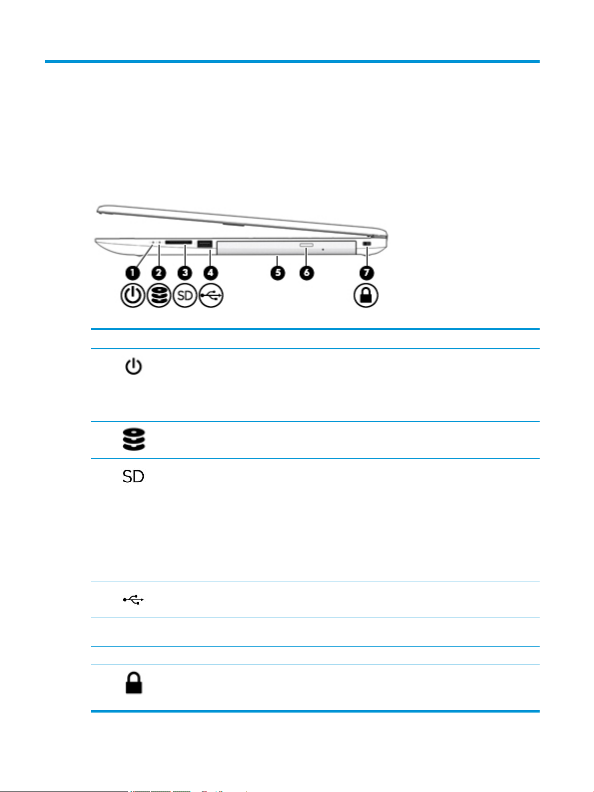
Right side
Table 2-1 Right-side components and their descriptions
Component Description
(1) Power light ● On: The computer is on.
● Blinking: The computer is in the Sleep state, a power-saving state. The
computer shuts o power to the display and other unneeded components.
● O: The computer is o or in Hibernation. Hibernation is a power-saving state
that uses the least amount of power.
(2) Drive light ● Blinking white: The hard drive is being accessed.
(3) Memory card reader Reads optional memory cards that enable you to store, manage, share, or access
information.
To insert a card:
1. Hold the card label-side up, with connectors facing the computer.
2. Insert the card into the memory card reader, and then press in on the card
until it is rmly seated.
To remove a card:
▲ Pull to remove the card from the memory card reader.
(4) USB port Connects a USB device, such as a cell phone, camera, activity tracker, or
smartwatch, and provides data transfer.
(5) Optical drive Depending on your computer model, reads an optical disc or reads and writes to an
optical disc.
(6) Optical drive eject button Releases the optical drive disc tray.
(7) Security cable slot Attaches an optional security cable to the computer.
NOTE: The security cable is designed to act as a deterrent, but it may not prevent
the computer from being mishandled or stolen.
6 Chapter 2 Getting to know your computer
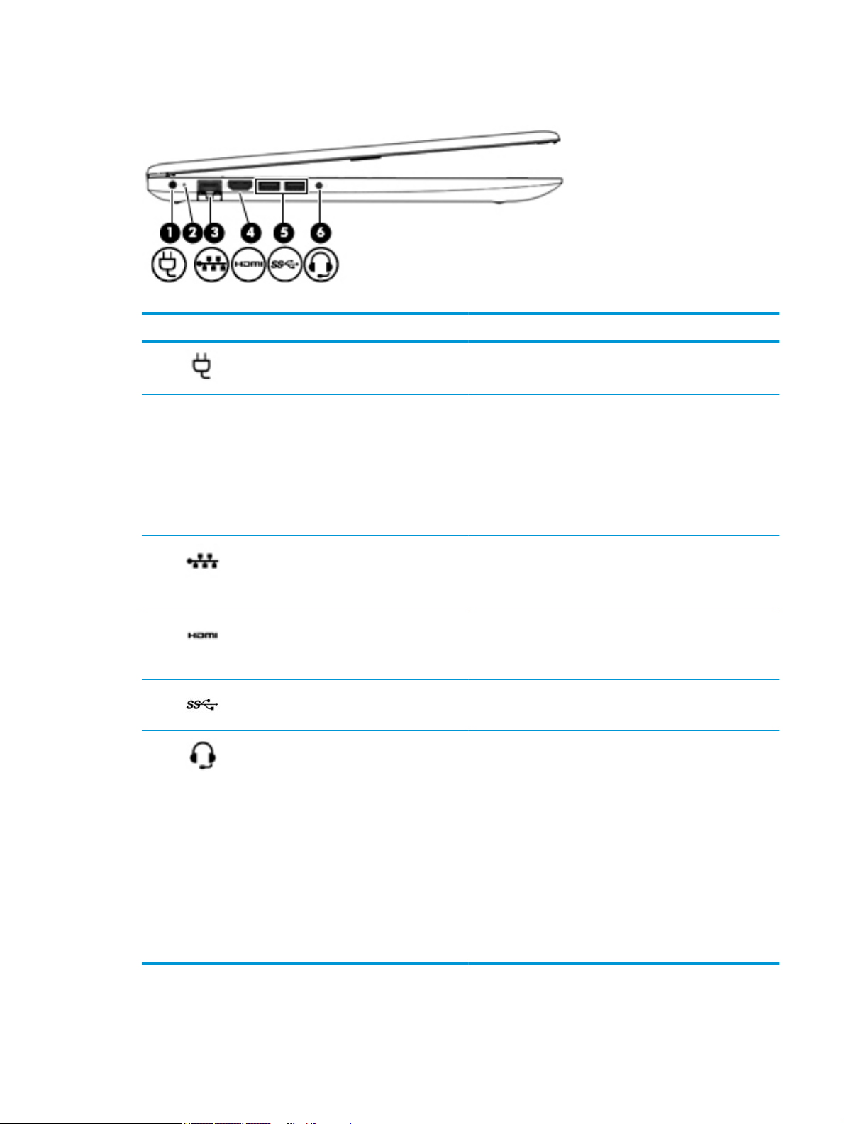
Left side
Table 2-2 Left-side components and their descriptions
Component Description
(1) Power connector Connects an AC adapter.
(2) AC adapter and battery light ● White: The AC adapter is connected and the battery is fully
charged.
● Blinking white: The AC adapter is disconnected and the
battery has reached a low battery level.
● Amber: The AC adapter is connected and the battery is
charging.
● O: The battery is not charging.
(3) RJ-45 (network) jack/status lights Connects a network cable.
● White: The network is connected.
● Amber: Activity is occurring on the network.
(4) HDMI port Connects an optional video or audio device, such as a high-
(5) USB SuperSpeed ports (2) Connect a USB device, such as a cell phone, camera, activity
(6) Audio-out (headphone)/Audio-in (microphone)
combo jack
denition television, any compatible digital or audio component,
or a high-speed High-Denition Multimedia Interface (HDMI)
device.
tracker, or smartwatch, and provide high-speed data transfer.
Connects optional powered stereo speakers, headphones,
earbuds, a headset, or a television audio cable. Also connects an
optional headset microphone. This jack does not support
optional standalone microphones.
WARNING! To reduce the risk of personal injury, adjust the
volume before putting on headphones, earbuds, or a headset.
For additional safety information, see the Regulatory, Safety,
and Environmental Notices.
To access this guide:
▲ Select the Start button, select HP Help and Support, and
then select HP Documentation.
NOTE: When a device is connected to the jack, the computer
speakers are disabled.
Left side 7
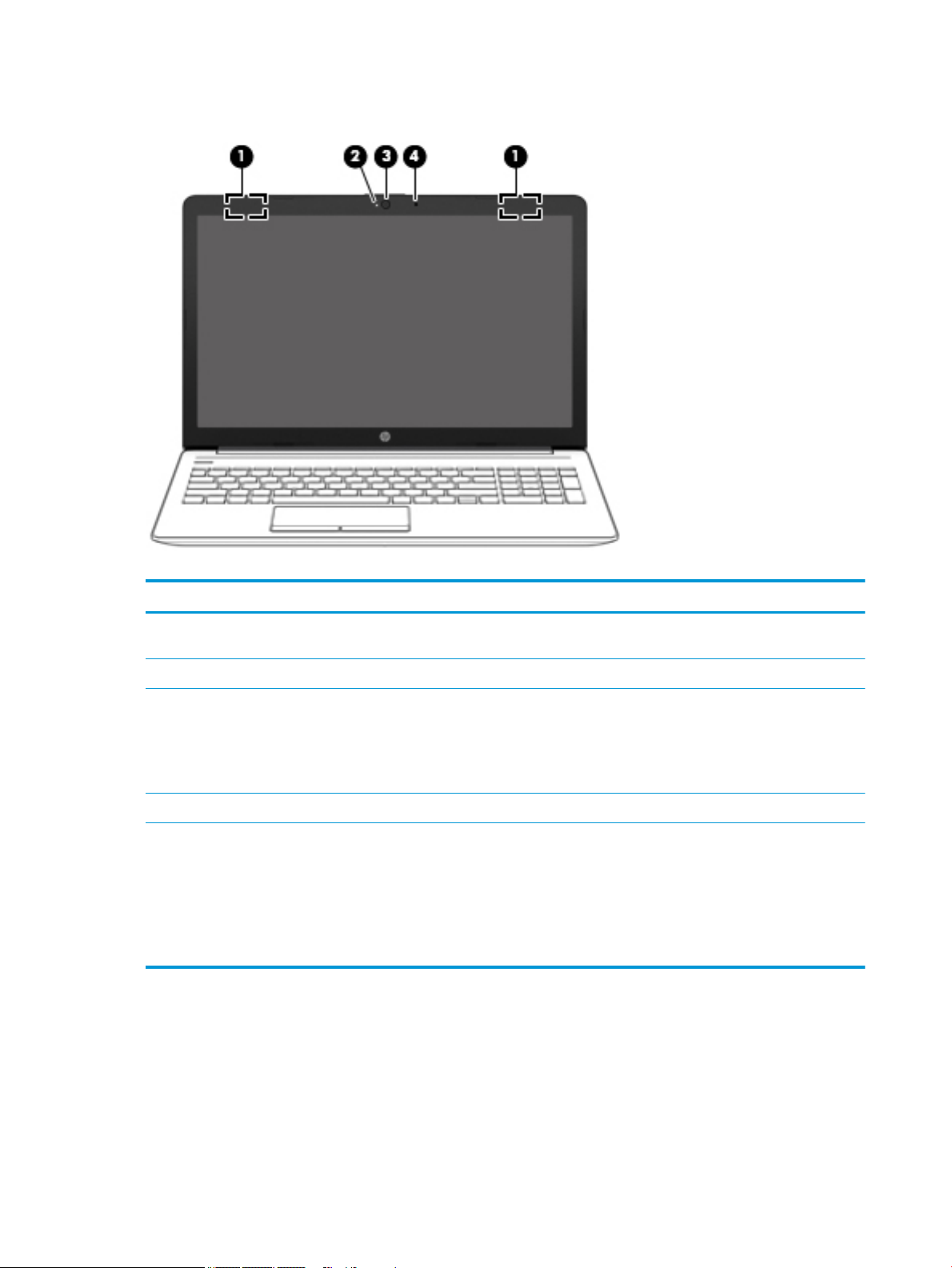
Display
Table 2-3 Display components and their descriptions
Component Description
(1) WLAN antennas* (1 or 2 depending on model) Send and receive wireless signals to communicate with wireless local
area networks (WLANs).
(2) Camera light On: The camera is in use.
(3) Camera Allows you to video chat, record video, and record still images. Some
(4) Internal microphone Records sound.
*The antennas are not visible from the outside of the computer. For optimal transmission, keep the areas immediately around the
antennas free from obstructions.
For wireless regulatory notices, see the section of the Regulatory, Safety, and Environmental Notices that applies to your country or
region.
To access this guide:
▲ Select the Start button, select HP Help and Support, and then select HP Documentation.
cameras also allow a facial recognition logon to Windows, instead of
a password logon..
NOTE: Camera functions vary depending on the camera hardware
and software installed on your product.
8 Chapter 2 Getting to know your computer
Keyboard area
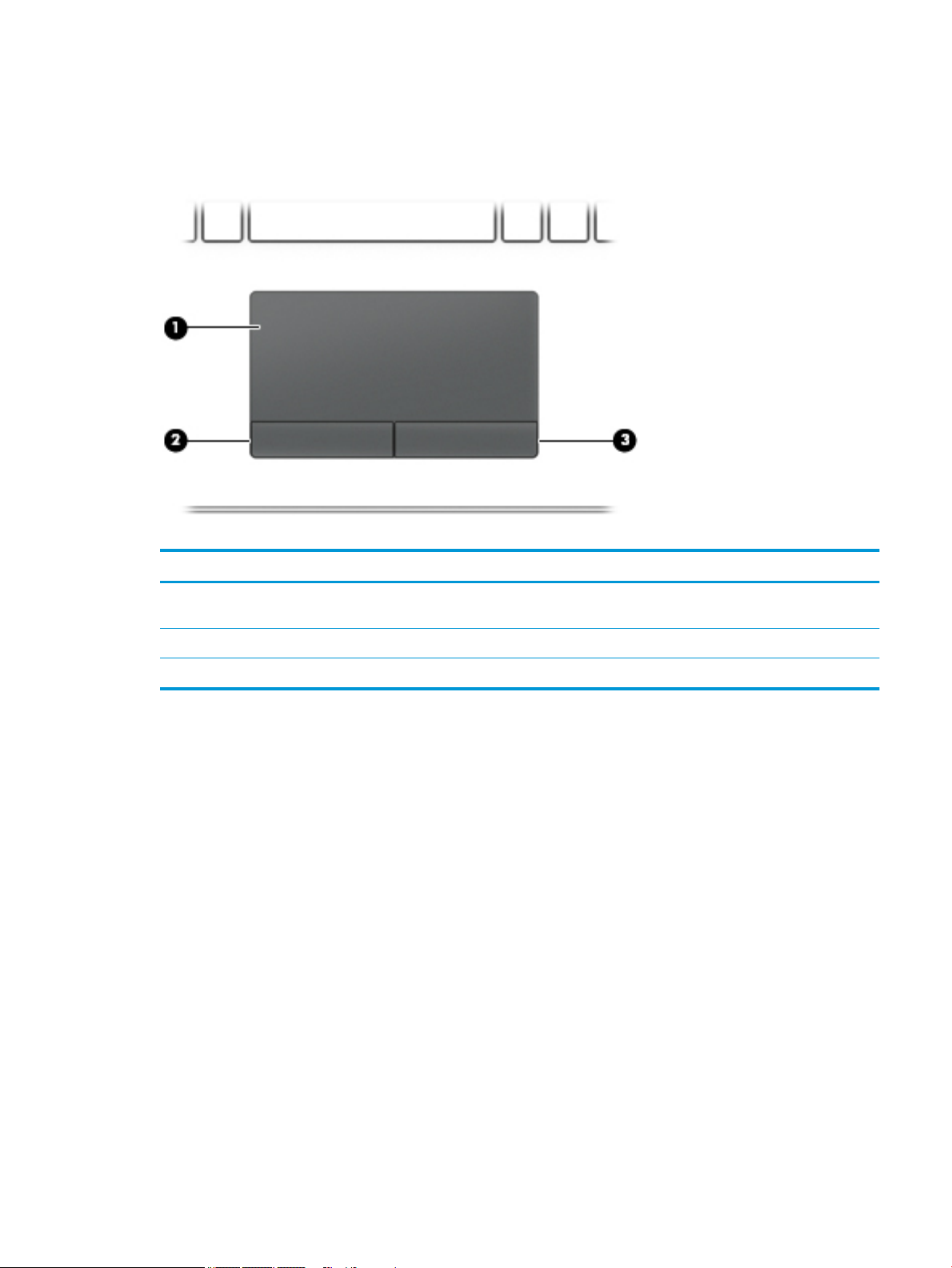
TouchPad
Table 2-4 TouchPad components and their descriptions
Component Description
(1) TouchPad zone Reads your nger gestures to move the pointer or activate items
on the screen.
(2) Left TouchPad button Functions like the left button on an external mouse.
(3) Right TouchPad button Functions like the right button on an external mouse.
Keyboard area 9
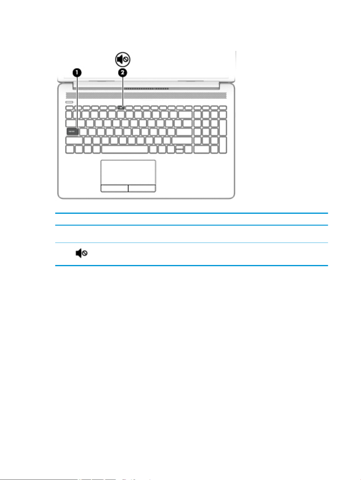
Lights
Table 2-5 Lights and their descriptions
Component Description
(1) Caps lock light On: Caps lock is on, which switches the key input to all capital
letters.
(2) Mute light ● Amber: Computer sound is o.
● O: Computer sound is on.
10 Chapter 2 Getting to know your computer
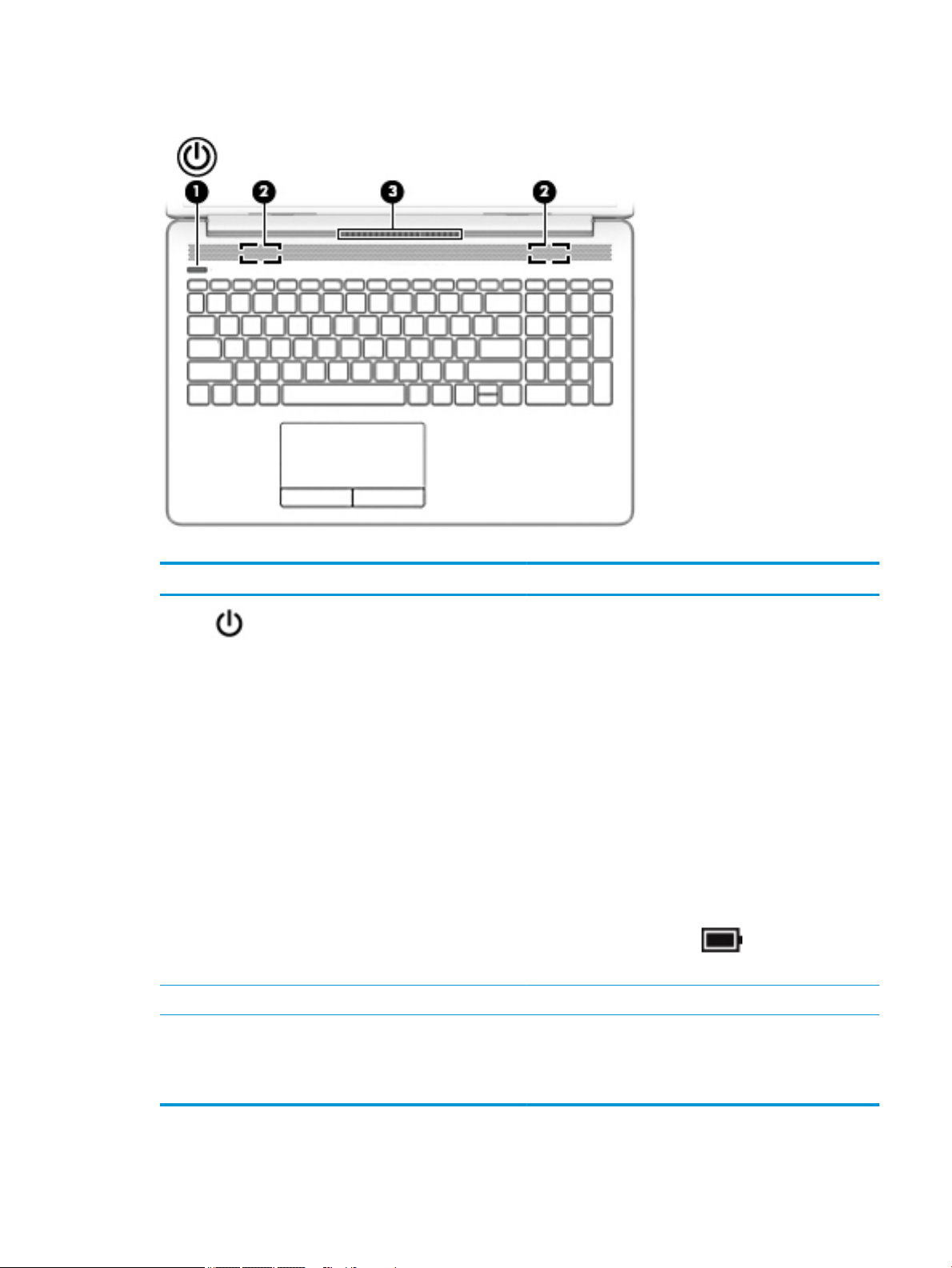
Button, speakers, and vent
Table 2-6 Button, speakers, and vent and their descriptions
Component Description
(1) Power button ● When the computer is o, press the button to turn on the
computer.
● When the computer is on, press the button briey to
initiate Sleep.
● When the computer is in the Sleep state, press the button
briey to exit Sleep.
● When the computer is in Hibernation, press the button
briey to exit Hibernation.
CAUTION: Pressing and holding down the power button results
in the loss of unsaved information.
If the computer has stopped responding and shutdown
procedures are ineective, press and hold the power button
down for at least 5 seconds to turn o the computer.
To learn more about your power settings, see your power
options:
▲ Right-click the Power icon , and then select Power
Options.
(2) Speakers (2) Produce sound.
(3) Vent Enables airow to cool internal components.
NOTE: The computer fan starts up automatically to cool
internal components and prevent overheating. It is normal for
the internal fan to cycle on and o during routine operation.
Keyboard area 11
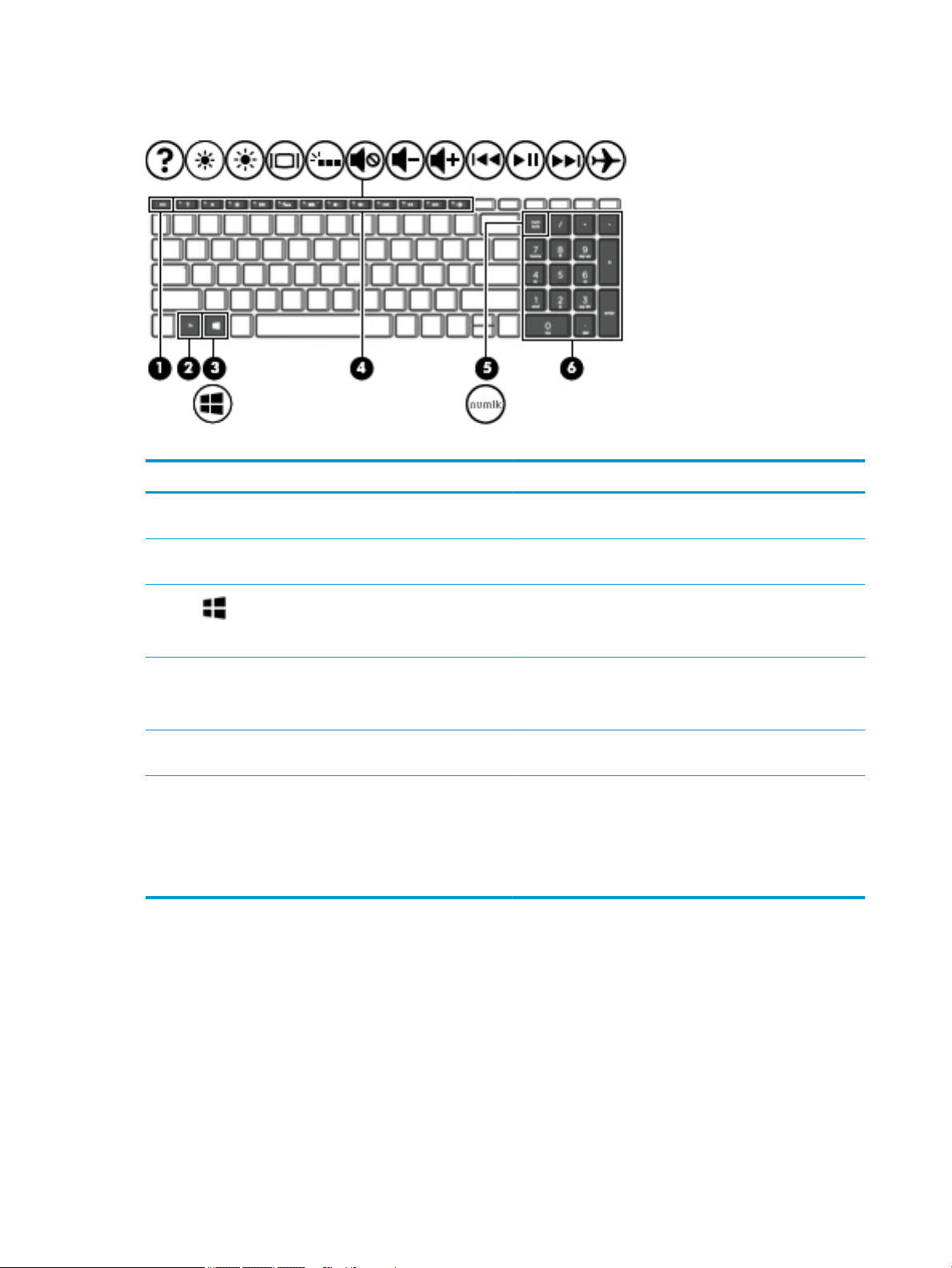
Special keys
Table 2-7 Special keys and their descriptions
Component Description
(1) esc key Displays system information when pressed in combination with
(2) fn key Executes specic functions when pressed in combination with
the fn key.
another key.
(3) Windows key Opens the Start menu.
NOTE: Pressing the Windows key again will close the Start
menu.
(4) Action keys Execute frequently used system functions.
NOTE: On select products, the f5 action key turns the keyboard
backlight feature o or on.
(5) num lock key Alternates between the navigational and numeric functions on
the integrated numeric keypad.
(6) Integrated numeric keypad A separate keypad to the right of the alphabet keyboard. When
num lock is pressed, the keypad can be used like an external
numeric keypad.
NOTE: If the keypad function is active when the computer is
turned o, that function is reinstated when the computer is
turned back on.
12 Chapter 2 Getting to know your computer
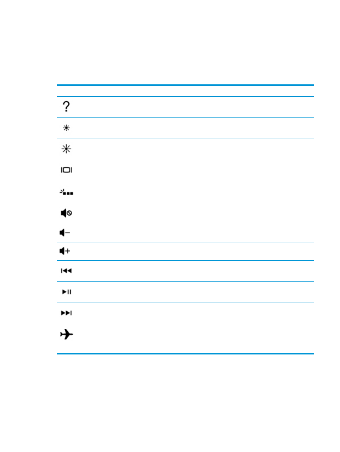
Action keys
An action key performs the function indicated by the icon on the key. To determine which keys are on your
product, see Special keys on page 12.
▲ To use an action key, press and hold the key.
Table 2-8 Actions keys and their descriptions
Icon Description
Opens the “How to get help in Windows 10” webpage.
Decreases the screen brightness incrementally as long as you hold down the key.
Increases the screen brightness incrementally as long as you hold down the key.
Switches the screen image between display devices connected to the system. For example, if a monitor is
connected to the computer, repeatedly pressing this key alternates the screen image from the computer
display to the monitor display to a simultaneous display on both the computer and the monitor.
Turns the keyboard backlight o or on.
NOTE: To conserve battery power, turn o this feature.
Mutes or restores speaker sound.
Decreases speaker volume incrementally while you hold down the key.
Increases speaker volume incrementally while you hold down the key.
Plays the previous track of an audio CD or the previous section of a DVD or a Blu-ray Disc (BD).
Starts, pauses, or resumes playback of an audio CD, a DVD, or a BD.
Plays the next track of an audio CD or the next section of a DVD or a BD.
Turns the airplane mode and wireless feature on or o.
NOTE: The airplane mode key is also referred to as the wireless button.
NOTE: A wireless network must be set up before a wireless connection is possible.
Keyboard area 13
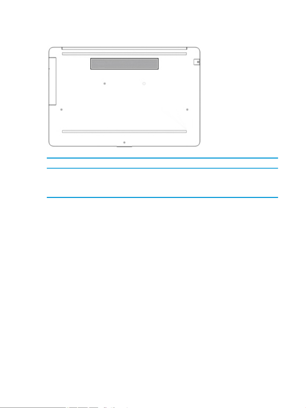
Bottom
Table 2-9 Bottom component and its description
Component Description
Vent Enables airow to cool internal components.
NOTE: The computer fan starts up automatically to cool internal
components and prevent overheating. It is normal for the internal fan
to cycle on and o during routine operation.
14 Chapter 2 Getting to know your computer
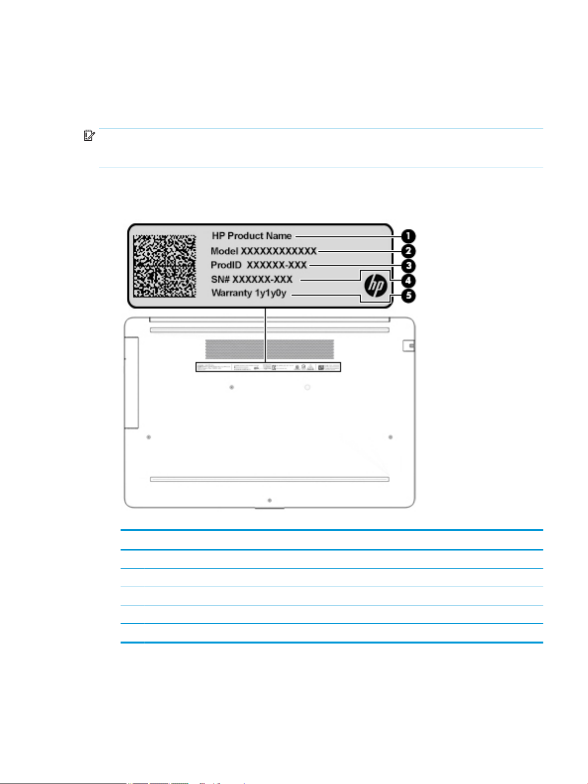
Labels
The labels axed to the computer provide information you may need when you troubleshoot system
problems or travel internationally with the computer. Labels may be in paper form or imprinted on the
product.
IMPORTANT: Check the following locations for the labels described in this section: the bottom of the
computer, inside the battery bay, under the service door, on the back of the display, or on the bottom of a
tablet kickstand.
● Service label—Provides important information to identify your computer. When contacting support, you
may be asked for the serial number, the product number, or the model number. Locate this information
before you contact support.
Table 2-10 Service label components
Component
(1) HP product name
(2) Model number
(3) Product ID
(4) Serial number
(5) Warranty period
● Regulatory label(s)—Provide(s) regulatory information about the computer.
● Wireless certication label(s)—Provide(s) information about optional wireless devices and the approval
markings for the countries or regions in which the devices have been approved for use.
Labels 15
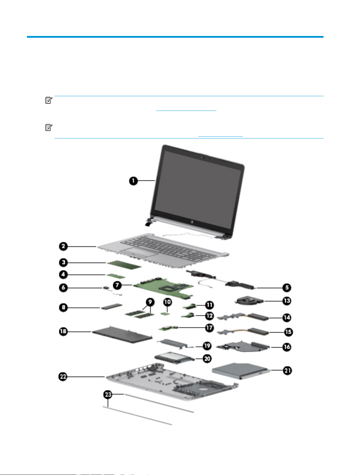
3 Illustrated parts catalog
Computer major components
NOTE: HP continually improves and changes product parts. For complete and current information on
supported parts for your computer, go to http://partsurfer.hp.com, select your country or region, and then
follow the on-screen instructions.
NOTE: Details about your computer, including model, serial number, product key, and length of warranty,
are on the service tag at the bottom of your computer. See Labels on page 15 for details.
16 Chapter 3 Illustrated parts catalog

Table 3-1 Computer major components and their descriptions
Item Component Spare part
number
(1) Display
NOTE: Displays are not spared as whole units. Display subcomponent spare parts are available. For
spare part information, see Display assembly subcomponents on page 22.
(2) Top cover/keyboard
NOTE: For a detailed list of country codes, see Top cover with keyboard on page 76.
Keyboard, no backlight, jet black L20387-xx1
Keyboard, no backlight, full-featured models, snow white L20388-xx1
Keyboard, no backlight, defeatured models, snow white L23066-xx1
Keyboard, no backlight, ash silver L20386-xx1
Keyboard, backlit, ash silver (available only with -001 United States, -002 India, and -DB1 Canadian
French keyboards)
Keyboard, no backlight, iridescent pale rose gold (available only with -001 United States keyboards) L28504-001
Keyboard, backlit, iridescent pale rose gold (available only with -001 United States keyboards) L28505-001
Keyboard, no backlight, iridescent ceramic white (available only with -001 United States keyboards) L28506-001
Keyboard, backlit, iridescent ceramic white (available only with -001 United States keyboards) L28507-001
Keyboard, no backlight, ocean teal (available only with -001 United States keyboards) L31735-001
Keyboard, no backlight, Real Tree (available only with -001 United States keyboards) L31736-001
Not spared
L23074-xx1
Keyboard, no backlight, natural silver (available only with -002 India keyboards) L32368-002
Keyboard, backlit, ocean teal (available only with -001 United States keyboards) L32863-001
Keyboard, backlit, natural silver (available only with -002 India keyboards) L32864-002
(3) TouchPad module L20449-001
(4) TouchPad button board not spared
(5) Speakers (include cable) L20453-001
(6) Power connector cable (DC-in) L20475-001
(7) System board
NOTE: All system board spare part kits include replacement thermal material.
All system boards use the following part numbers:
xxxxxx-001: Non-Windows operating systems
xxxxxx-601: Windows operating system
For use in models with discrete graphics memory:
● AMD Athlon 300U processor and Radeon 530 graphics L53469-xx1
● AMD Ryzen 3-3200U processor and Radeon 530 graphics L46517-xx1
● AMD Ryzen 3-2200U processor and Radeon 530 graphics L20668-xx1
● AMD A9-9425 processor and Radeon 530 graphics L46513-xx1
Computer major components 17

Table 3-1 Computer major components and their descriptions (continued)
Item Component Spare part
number
● AMD A9-9425 processor and Radeon 520 graphics L20480-xx1
● AMD A6-9225 processor and Radeon 530 graphics L46514-xx1
● AMD A6-9225 processor and Radeon 520 graphics L20481-xx1
For use in models with UMA graphics memory:
● AMD Ryzen 7-3700U processor L51325-xx1
● AMD Ryzen 5-3500U processor L46515-xx1
● AMD Ryzen 3-3200U processor L46516-xx1
● AMD Ryzen 5-2500U processor L20664-xx1
● AMD Ryzen 3-2300U processor L20665-xx1
● AMD Ryzen 3-2200U processor L20666-xx1
● AMD A9-9425 processor L20477-xx1
● AMD A6-9225 processor L20478-xx1
● AMD A4-9125 processor L31720-xx1
● AMD E2-9000e processor L20479-xx1
(8) Solid-state drive
NOTE: For spare part information, see Mass storage devices on page 26.
(9) Memory modules (2400 MHz DDR4)
8 GB 862398-855
4 GB 862397-855
(10) WLAN module
Realtek RTL8822BE 802.11ac 2 × 2 Wi-Fi + Bluetooth 4.2 Combo Adapter (MU-MIMO supported) 924813-855
Realtek RTL8821CE 802.11ac 1 × 1 Wi-Fi + Bluetooth 4.2 Combo Adapter (MU-MIMO supported) L17365-005
Realtek RTL8723DE 802.11bgn 1 × 1 Wi-Fi + Bluetooth 4.2 Combo Adapter L21480-005
(11) Hard drive connector board L20454-001
(12) Solid-state drive connector board L20457-001
(13) Fan
For use in models with discrete graphics L20473-001
For use in models with UMA graphics L20474-001
(14) Heat sink for use in models with AMD Ryzen processors and discrete graphics L20482-001
Heat sink for use in models with AMD A6/A9 processors and discrete graphics L20484-001
(15) Heat sink for use in models with AMD Ryzen processors and integrated UMA graphics L20483-001
Heat sink for use in models with AMD A6/A9 processors and integrated UMA graphics L20491-001
(16) Heat sink for use in fanless models with AMD E2-9000e processors L20494-001
18 Chapter 3 Illustrated parts catalog

Table 3-1 Computer major components and their descriptions (continued)
Item Component Spare part
number
(17) USB/card reader board
The USB/card reader board cable is available using spare part number L20452-001.
(18) Battery (3-cell, 41 Whr) L11119-855
(19) Solid-state drive bracket L20458-001
(20) Hard drive
NOTE: For spare part information, see Mass storage devices on page 26.
(21) DVD+/-RW Double-Layer Writer L20485-001
(22) Bottom cover
For use in models with an optical drive
● Snow white L20389-001
● Jet black L20390-001
● Natural silver L20391-001
● Pale gold L20392-001
● Twilight blue L20393-001
● Scarlet red L20397-001
● Smoke gray L20395-001
L20448-001
● Maroon burgundy L20398-001
● Iridescent pale rose gold L28510-001
● Iridescent ceramic white L28512-001
● Ocean teal L31725-001
● Real Tree L31726-001
● Berry mauve; Pattern: mesh knit L50283-001
● Chalkboard gray; Pattern: mesh knit L50284-001
● Jet black; Pattern: mesh knit L50285-001
● Lumiere blue; Pattern: mesh knit L50286-001
● Snow white; Pattern: mesh knit L50288-001
For use in models without an optical drive
● Snow white L20399-001
● Jet black L20400-001
● Natural silver L20401-001
● Pale gold L20402-001
● Pale rose gold L57161-001
● Twilight blue L20403-001
Computer major components 19

Table 3-1 Computer major components and their descriptions (continued)
Item Component Spare part
number
● Scarlet red L20405-001
● Smoke gray L20404-001
● Iridescent pale rose gold L28511-001
● Iridescent ceramic white L28513-001
● Maroon burgundy L31719-001
● Berry mauve: Pattern: mesh knit L50289-001
● Chalkboard gray: Pattern: mesh knit L50290-001
● Jet black; Pattern: mesh knit L50291-001
● Lumiere blue; Pattern: mesh knit L50292-001
● Snow white; Pattern: mesh knit L50293-001
(23) Front rubber feet
Pale gold L20408-001
Pale rose gold L57162-001
Iridescent pale rose gold L28518-001
Scarlet red L20411-001
Twilight blue L20409-001
Maroon burgundy L20412-001
Dark ash silver L20406-001
Asteroid silver L20407-001
Ocean teal L31731-001
Real Tree L31732-001
Berry mauve; Pattern: mesh knit L50314-001
Lumiere blue; Pattern: mesh knit L50317-001
(23) Rear rubber feet:
Pale gold L20415-001
Pale rose gold L57163-001
Iridescent pale rose gold L28519-001
Scarlet red L20418-001
Twilight blue L20416-001
Maroon burgundy L20419-001
Dark ash silver L20413-001
Asteroid silver L20414-001
Ocean teal L31733-001
20 Chapter 3 Illustrated parts catalog
 Loading...