


Hozelock Cyprio Cascade 1500, 3354 Installation And Operating Instructions Manual

The Hozelock Cyprio Cascade 1500
pump is designed for submersible use only.
The pump does not use oil or grease for
lubrication and can be used safely in ponds
containing fish or plants. The motor consists
of a sealed stator and water-cooled
permanent magnet rotor. All electrical
components are isolated from the water.
IMPORTANT
1. WARNING: ALWAYS UNPLUG OR
DISCONNECT ALL APPLIANCES IN THE
POND FROM THE ELECTRICITY SUPPLY
BEFORE PUTTING YOUR HANDS IN THE
WATER WHILST EQUIPMENT IS BEING
INSTALLED, REPAIRED, MAINTAINED OR
HANDLED.
2. Do not use the supply cable to lift the
pump, as this may cause damage. We
recommend fitting a lifting cord to the
handle eye on the top of the strainer cage
when the pump is installed in deep water.
3. Do not operate or leave the pump in
freezing conditions.
4. Do not allow the pump to run dry.
5. Check that the voltage marked on the
pump corresponds to the mains supply.
6. A 10MA OR 30 MA RESIDUAL CURRENT
DEVICE MUST
BE FITTED TO THE MAINS
SUPPLY.
7. DO NOT OPERATE THIS PUMP
WITHOUT THE STRAINER CAGE
ATTACHED. USING THE PUMP WITHOUT A
STRAINER CAGE MAY INVALIDATE YOUR
WARRANTY.
Safety Information
The appliance is not intended for
use by persons (including children)
with reduced physical, sensory or
mental capabilities, or lack of
experience and knowledge, unless
they have been given supervision or
instruction concerning use of the
appliance by a person responsible
for their safety. Children should be
supervised to ensure that they do
not play with the appliance.
(Australia & NZ only) This appliance
is not intended for use by young
children or infirm persons unless
they have been adequately
supervised by a responsible person
to ensure that they can use the
appliance safely.
Young children should be supervised
to ensure that they do not play with
the appliance.
WARNING: SAFETY AND
ELECTRICAL CONNECTIONS
1. The pump is supplied with 10m of 3 core
electric cable which is permanently
connected and sealed to the motor.
The supply cable cannot be replaced. If the
cable is damaged, the pump should be
discarded.
This product is designed to be
permanently wired to the mains supply in
a dry weatherproof enclosure through a
Double-Pole Switched Fused Spur (Disconnector) to BS 3676, with a
minimum contact separation of 3mm in
each Pole - Fitted with a 3 or 5 Amp fuse.
The installation must conform to the
national and local wiring regulations
which could include the use of plastic or
metal conduit to protect the cable.
2. A 10MA OR 30MA RESIDUAL CURRENT
DEVICE (RCD) MUST
BE FITTED TO THE
MAINS SUPPLY.
3. WARNING: THIS APPLIANCE MUST
BE
EARTHED AND IT IS ESSENTIAL THAT THE
CONNECTIONS ARE MADE USING THE
FOLLOWING CODE;
Brown - Live
Blue - Neutral
Green/Yellow - Earth
The BROWN lead should be connected to
the LIVE terminal which may be marked
with an ‘L’ or coloured brown or red.
The BLUE lead should be connected to the
NEUTRAL terminal which may be marked
with an ‘N’ or coloured blue or black.
The GREEN/YELLOW lead should be
connected to the EARTH terminal which
may be marked with an ‘E’ or coloured
green or green/yellow.
4. If an extension cable is required, this
should be connected to the end of the
pump cable using a weatherproof cable
connector. The joint must be positioned in
a suitable weatherproof housing. The
extension cable should be of 3 core
0.75mm
2
Polychloroprene rubber insulated
cable (ref: HO5 RN-F) and permanently
wired to the mains supply with a 3 or 5
Amp fuse.
5. The pump cable (and extension cable)
should be positioned and adequately
protected against damage especially
where contact with gardening equipment
(lawn mowers, forks etc.) children and
domestic animals may occur.
6. CONSULT A QUALIFIED ELECTRICIAN OR
LOCAL AUTHORITY IF IN ANY DOUBT
ABOUT WIRING TO THE MAINS SUPPLY.
ACCESSORY ASSEMBLY
Tee Piece
1. Locate the fountain flow adjuster (See
Fig1-A) to the tee piece body with the peg
positioned downwards to engage in the
tee. Push in fully and snap them together.
2. Locate the valve stem (B) to the waterfall
flow adjuster (C) and snap them together.
Screw the valve assembly into the longer
boss (D) on the tee piece. See fig 1.
Telescopic Stem
1. Slide the Inner Tube (E) through the
Telescopic Stem Nut (F) and “O” ring (G).
Push the Inner Tube into the Outer Tube
(H) and gently screw down the nut. The
finishing position of the tee piece is not
important. The maximum to minimum
range of the Telescopic stem is 150mm
(6”) (See fig 2).
Bell Fountain
1. Locate the Bell Support (I) to the Bell Main
Body (J) and push fully home.
2. Position the Bell (K) to the Body Assembly
and press into the central location.
See fig 3.
PUMP INSTALLATION
Position
Construct a solid and level platform on which
to place the pump. For installations using the
fountain tops directly on the Tee Piece, the
top level of the platform should be 300 mm
(12”) below the water level. For installations
using the fountain tops directly on the Tee
Piece and Telescopic Stem , the top level of
the platform should be 450 mm (18”) below
the water level.
Fountain Only. (See Fig 7 for general
installation guide)
1. Place the pump next to the pond and
route the cable back to the mains supply.
2. Position the pump with the Tee Piece
Assembly and if required the Telescopic
Stem with the fountain fitted in the
desired position in the pond. The 2 and 3
tierfountain heads simply snap onto the
fountain stem (See Fig 4).
3. The fountain height can be regulated to
suit your needs by rotating the Fountain
Flow Adjuster. See Fig 5 (L).
4. If required, the 2-Tier Fountain head, Fig 5
(M), can be used to achieve an alternative
and higher display pattern than the 3-Tier,
Fig 5 (N).
5. The Bell Fountain creates a decorative
waterbell. The size of the bell can be
regulated by adjusting the flow through
the Tee Piece by rotating the fountain
flow adjuster and or by raising or lowering
Cascade 1500
INSTALLATION AND OPERATING INSTRUCTIONS. READ INSTRUCTIONS CAREFULLY BEFORE ATTEMPTING INSTALLATION.
KEEP THESE INSTRUCTIONS FOR FUTURE REFERENCE
3354
ATTENTION
AUTOMATIC CUT-OUT. To help ensure
your pump’s long life and to prevent
damage, it is fitted with automatic
thermal overload protection. This
switches off the pump if it overheats. If
this occurs, switch off the power at the
mains supply to the pump. Check for the
cause. Usually it will be debris blocking
the inlets of the pump or obstructing the
impeller. Remove the obstruction and
wait 15 minutes for the pump to cool
down and automatically reset. Then
switch on the pump again.
NOTE: YOU MUST SWITCH OFF THE MAINS
SUPPLY BEFORE THE PUMP WILL RESET.
From 1st January 2005 installing this
product in the garden is classed as
'notifiable' in the revised Building
Regulations for England and Wales. The
Regulations now require you to tell
your local authority building control
department that you intend to install
this product before installation. Your
local authority will let you know how
you can get your installation approved.
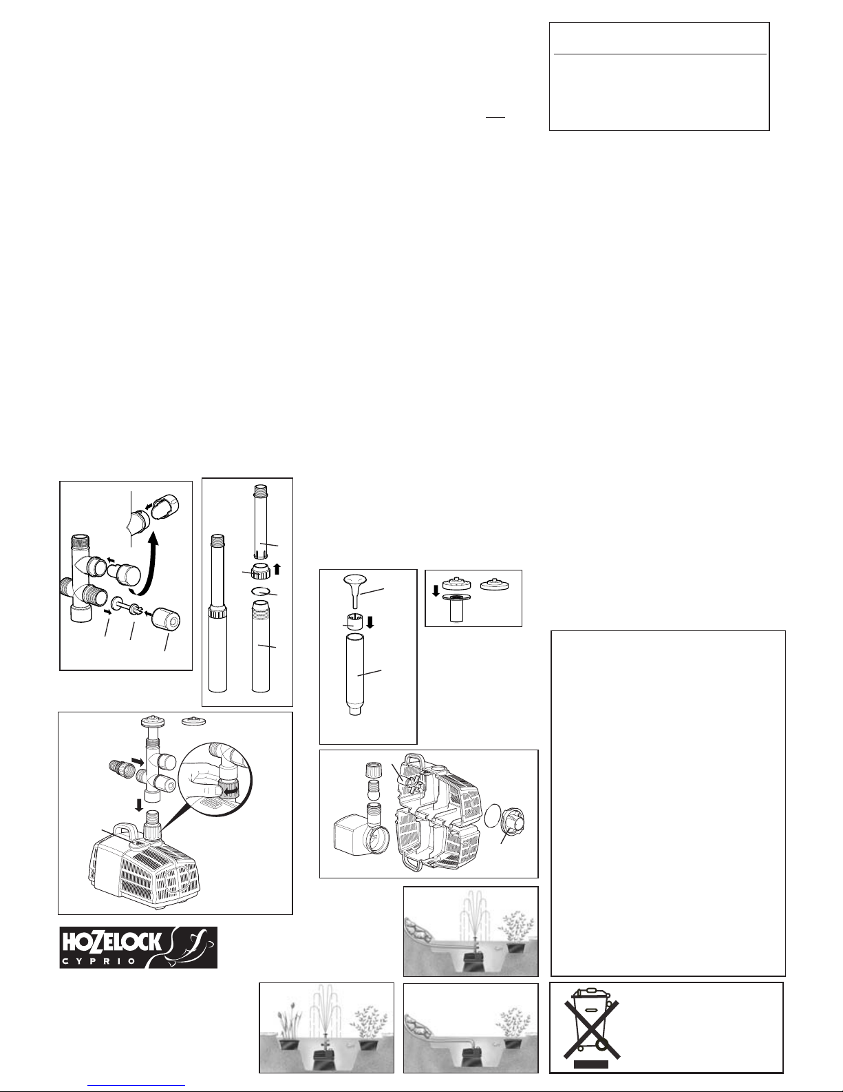
the top of the Bell in main Bell Body.
6. The ball joint on the bottom of the tee
Piece, Fig 5(O) can be used to adjust the
fountain angle so that it is vertical.
Fountain and Waterfall. (See Fig 8 for general
installation guide)
1. Position the pump as previously described.
2. Attach a suitable length of 25 mm (1”)
hose to the Threaded Hose tail, Fig 5 (P),
and secure with a suitable hose clip and
position the outlet end of the hose in the
desired position.
3. Screw the Threaded Hose tail onto the
waterfall outlet side of the Tee Piece.
4. The combination of waterfall and
fountain will reduce the fountain height
that can be achieved.
5. Once the pump is operating the flow of
the waterfall and the height of the
fountain can be independently adjusted.
Waterfall Only. (See Fig 9 for general
installation guide)
1. Position the pump as previously described.
2. Attach a suitable length of 25 mm (1”)
hose to the Threaded Hose tail and secure
with a suitable hose clip and position the
outlet end of the hose in the desired
position.
3. For maximum waterfall flow, screw the
Threaded Hose tail directly onto the outlet
of the pump. Some installations require
the flow of the water to be adjusted. In
these cases, screw the Tee Piece to the
outlet of the pump, screw the Threaded
Hose tail to the water fall outlet boss and
adjust the flow using the waterfall flow
adjuster, Fig 5 (Q), to suit your needs.
MAINTENANCE
The Hozelock Cyprio range of Cascade pumps
has been designed to allow fast and easy
maintenance. As with all pumps of its kind,
occasionally it will become necessary to clean
the Strainer Cage and Fountain Spray head
ring.
ALWAYS UNPLUG OR DISCONNECT ALL
APPLIANCES IN THE POND FROM THE
ELECTRICITY SUPPLY BEFORE PUTTING YOUR
HANDS IN THE WATER OR STARTING
MAINTENANCE.
Fountain Head
1. Place a coin or similar in the slot and
gently lever off the fountain head.
2. Rinse in clean water and reassemble.
Strainer
1. Remove the accessories from the pump
outlet.
2. Holding the pump in one hand, press the
release button on the top of the pump
and open Strainer Cage. See Fig 5 (R).
3. Slide the pump out of its location and
wash/rinse the Strainer Cage with clean
water. The hinges on the Strainer Cage
should also be washed clean at this time.
4. Reassemble the pump.
Rotor Assembly
1. Remove the Strainer Cage as described
above.
2. Release the Pump Chamber, Fig 6 (S), by
rotating it until the two retaining tongues
are clear of the lugs on the Motor Body.
3. Gently pull the Pump Chamber squarely
away from the Motor Body.
4. Pull the Rotor Assembly out of the Motor
Body. See Fig 6 (T ).
5. Wash out all of the components in clean
water. Do not use detergents or other
chemical cleaners.
6. Replace the Rotor Assembly into the
Motor Body and refit the Pump Chamber
and Strainer Cage.
ALL YEAR PUMP CARE
A quick daily check should be carried out to
ensure that the pump is performing
satisfactorily.
Once a week- Remove and clean the Strainer
Cage and Fountain Head in accordance with
the general maintenance notes. Depending
on pond water conditions, cleaning may be
required more frequently.
Once a year- Completely disassemble the
pump including the Rotor Assembly as
described in the general maintenance notes
and wash all components in clean, fresh
water. Replace worn or broken parts.
SPARE PARTS
Contact the Consumer Services Helpline on
0121 313 1122
HOZELOCK CYPRIO 3 YEAR
GUARANTEE
If this pump, excluding the Rotor Assembly,
becomes unserviceable within 3 years of the
date of purchase it will be repaired or
replaced at our option free of charge, unless
in our opinion it has been damaged or
misused.
Liability is not accepted for damage due to
accident, improper installation or use.
Liability is limited to replacement of a faulty
pump. This guarantee is not transferable. It
does not affect your statutory rights.
To obtain the benefits of the guarantee,
firstly contact Hozelock Cyprio Consumer
Services who may request that the pump is
sent along with proof of purchase directly to
the address below.
DAMAGE CAUSED BY RUNNING THE PUMP
DRY OR BY FROST INVALIDATES THE
GUARANTEE.
FAULT FINDING
WARNING: ALWAYS UNPLUG OR
DISCONNECT ALL APPLIANCES IN THE
POND FROM THE ELECTRICITY SUPPLY
BEFORE PUTTING YOUR HANDS IN THE
WATER WHILST EQUIPMENT IS BEING
INSTALLED, REPAIRED, MAINTAINED OR
HANDLED.
IMPORTANT - PLEASE KEEP THIS
SECTION FOR REFERENCE
LOW FLOW FROM PUMP
1. Ensure the Strainer Cage is clean.
2. A small diameter outlet pipe will
restrict outlet flow.
3. Clear any blockages and adjust the flow
controls.
NO FLOW FROM PUMP
1. Check power supply is on.
2. Check fuse and wiring.
3. Check the Rotor Assembly is not
jammed, damaged or showing signs of
excessive wear.
4. Ensure the Strainer Cage is clean.
POOR FOUNTAIN DISPLAY.
1. Clean the Fountain Head. (see
maintenance).
Fig. 1
Fig. 3
S
L
P
M
N
B
D
C
K
I
J
Fig. 7
Fig. 8
Fig. 9
Fig. 2
E
F
G
H
Fig. 5
A
Hozelock Cyprio
Midpoint Park, Birmingham B76 1AB
Tel: +44 (0)121 313 1122
www.hozelock.com
The Aquatics Division of Hozelock Group
33445-002
Item Numbers
1500
Pump Chamber and Seal. Z13254
Rotor Assembly. 3409
Strainer Cage. Z13214
Fountain Kit. 3403
Fig. 6
O
R
Fig. 4
Q
PLEASE NOTE:
Do not dispose
of in household
waste
T