

?
aquaforce
6000, 8000, 12000 &
15000
2823
1583
1584
1585
1586
Hozelock Ltd.
Midpoint Park,
Birmingham B76 1AB. England
Tel: +44 (0) 121 313 1122
info@hozelock.com
www.hozelock.com
43386-001
1
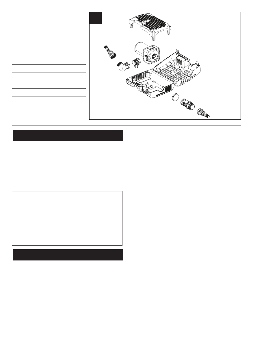
A
E
A. Wildlife Protection System
B. Pump
C. Outlet adaptor
D
D. Ball Joint
E. Hosetail & Nut
F. Strainer Cage
G. End Cap
H. Flow Control
Introduction
The pump is electrically operated and is designed to pump
solid particles up to 10mm in diameter with minimal prestrainer maintenance. These types of pumps are particularly
suitable for pumping water to external filters or for use in
high flow waterfalls or watercourse applications where low
maintenance is important. The pump does not use oil or
grease for lubrication and can be used safely in ponds
containing fish or plants. The motor consists of a sealed
stator and water-cooled rotor. All electrical components are
isolated from the water.
ATTENTION
AUTOMATIC CUT-OUT
To help ensure your pump’s long life and to prevent
damage, it is fitted with automatic thermal overload
protection. This switches off the pump if it overheats. If
this occurs, switch off the power at the mains supply to
the pump. Check for the cause. Usually it will be debris
blocking the inlets of the pump or obstructing the
impeller. Remove the obstruction and wait for the pump
to cool down. Then switch on the pump again.
General Safety Guidelines
Failure to observe the following notices may result in
injury, product damage or loss of fish.
1. This pump has been designed for the use with ponds
only. Only use this pump for the operation of pond
filter systems, water displays, waterfalls etc. Do not use
this pump for any other use (i.e. do not use this pump
in swimming pools, bathrooms, central heating systems
etc). Using the product for any other application may
result in injury or product damage.
2. This appliance is not intended for use by persons
(including children) with reduced physical, sensory or
mental capabilities, or lack of experience and
knowledge, unless they have been given supervision or
instruction concerning use of the appliance by a person
responsible for their safety. Children should be
supervised to ensure that they do not play with the
B
F
C
G
EH
appliance. (Australia & NZ only) This appliance is not
intended for use by young children or infirm persons
unless they have been adequately supervised by a
responsible person to ensure that they can use the
appliance safely. Young children should be supervised
to ensure that they do not play with the appliance.
3. WARNING: Always unplug or disconnect all appliances
in the pond from the electricity supply before putting
your hands in the water whilst equipment is being
installed, repaired, maintained or handled.
4. Never use the mains supply cable to lift the pump, as
this may cause damage. We recommend fitting a lifting
cord to the handle on the strainer cage when the pump
is installed in deep water.
5. Do not operate or leave the pump in freezing
conditions.
6. Protect the pump from direct sunlight. Direct sunlight
may overheat the motor.
7. Never allow the pump to run dry.
8. Do not operate this pump without the strainer cage
properly attached. Using the pump without the strainer
cage may invalidate your guarantee.
9. ATTENTION: This product is not suitable for water
temperatures above 35ºC.
10. ATTENTION: Do not operate this product if the mains
supply cable or the motor has become damaged in any
way. The supply cable cannot be replaced as it is
permanently encased in the motor housing and should
therefore be disposed of according to local regulations.
11. If you live in a hard water area (water with high
calcium or limescale content), the pump, rotor assembly
and inside of motor should be cleaned at regular
intervals (See MAINTENANCE).
12. Only use accessories which have been designed for use
with this product. The use of any other accessories may
invalidate your guarantee.
Installing this product in the garden is classed as
'notifiable' in the revised Building Regulations for
England and Wales. The Regulations require you to tell
your local authority building control department that
you intend to install this product before installation.
Your local authority will let you know how you can get
your installation approved.
Electrical Connections
1. WARNING: Always unplug or disconnect all appliances
in the pond from the electricity supply before putting
your hands in the water whilst equipment is being
nstalled, repaired, maintained or handled.
i
2. Check that the voltage marked on the unit corresponds
o the mains supply.
t
3. The pump is supplied with 10m of 3 core electric cable
which is permanently connected and sealed to the
otor.
m
he supply cable cannot be replaced. If the cable is
T
amaged, the pump should be discarded.
d
This product is designed to be permanently wired to the
mains supply in a dry weatherproof enclosure through a
ouble-Pole Switched Fused Spur - (Disconnector) to BS
D
3676 – with a minimum contact gap of 3mm in each
pole. Fitted with a 3 or 5 Amp fuse. The installation
must conform to the National and Local wiring
regulations which could include the use of plastic or
metal conduit to protect the cable.
4. A 10mA or 30mA Residual Current Device (RCD) Must
be fitted to the mains supply.
5. WARNING: This appliance must be earthed and it is
essential that the connections are made using the
following code;
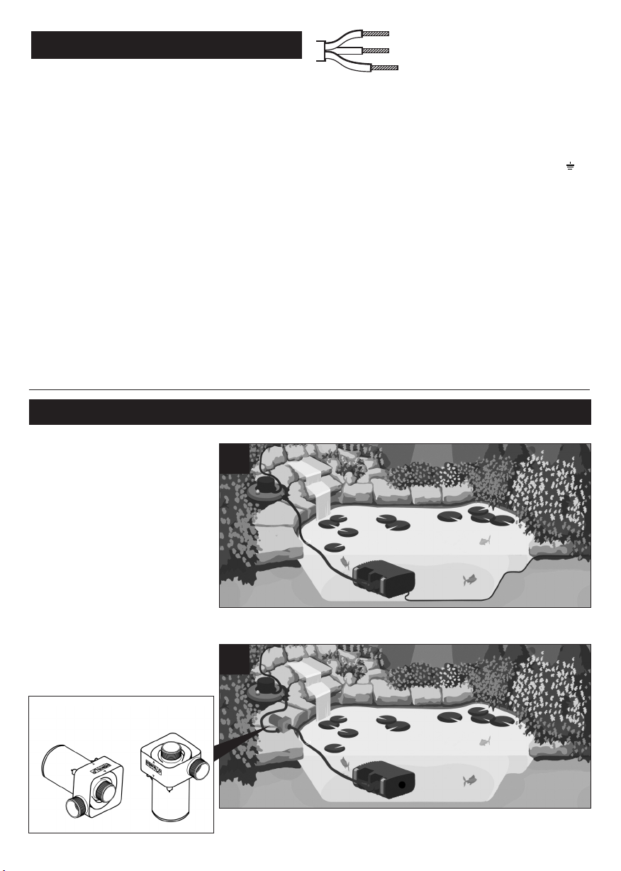
Typical Installation
rown – Live
B
Blue – Neutral
Green/Yellow – Earth
The BROWN lead should be connected to the LIVE
erminal which may be marked with an ‘L’ or coloured
t
brown or red.
he BLUE lead should be connected to the NEUTRAL
T
terminal which may be marked with an ‘N’ or coloured
blue or black.
he GREEN/YELLOW lead should be connected to the
T
ARTH terminal which may be marked with an ‘E’ ( ) or
E
oloured green or green/yellow.
c
6. If an extension cable is required, this should be
onnected to the end of the pump cable using a
c
weatherproof cable connector.
he joint must be positioned in a suitable dry housing.
T
The extension cable should be of 3 core 0.75mm2
Polychloroprene rubber insulated cable (ref: HO5 RN-F)
and permanently wired to the mains supply with a 3 or
5 Amp fuse.
7. The pump cable (and extension cable) should be
positioned and adequately protected against damage
especially where contact with gardening equipment,
(lawn mowers, forks etc..) children and domestic
animals may occur.
8. Consult a qualified electrician or local authority if in any
doubt about wiring to the mains supply.
NOTE: When running amphibiously,
the dry sited pump MUST be
positioned horizontally, as shown.
✓
✗
2
Most common Aquaforce set up
3
Amphibious operation

Pump Assembly & Installation
- Submerged Operation
ASSEMBLY
1. Open the clips at either end of the
trainer cage (Fig 1 – f) and open the
s
cage.
2. Remove the Wildlife Protection
ystem (Fig 1 – a).
s
3. Remove & unpack the ball joint,
hosetails & Flow control (Fig 1–d, e &
h).
4.Remove the mains supply cable and
ote:
N
For the 6000 & 8000 pump the adaptor
should be orientated with the outlet
at the bottom of the cage (fig 5).
For the 12000 & 15000 pumps, the
adaptor should be orientated with the
outlet towards the top of the cage (Fig
5).
6. Locate the mains supply cable into
the recess on the side of the cage.
Ensure it is seated in the correct
position so that the cable does not get
trapped when the cage is closed. (Fig
6).
nwind.
u
5. Ensure that the outlet of the pump
is secured to the outlet adaptor (Fig 1
– c). Locate the pump onto its
mounting area ensuring that the
daptor piece slots into the location
a
ribs in the front of the lower cage (Fig
).
4
4
5
6000/8000
12000/15000
6
7. Close the cage lid ensuring that the
end cap (Fig 1 – g) is in its correct
position and secure by pressing in the
centre of the clips (Fig 7).
8. Checking that the ball joint’s inlet
and outlet bosses are in line, firmly
screw the nut on to the screw thread
on the outlet adaptor (Fig 8).
7
8

300mm
9. Using small bore hoses leads to
xcessive restriction of the water flow.
e
The larger the diameter of hose that
ou use the better the performance of
y
the pump will be, especially over long
ose runs. The hosetail supplied with
h
this unit will accommodate 25mm (1"),
2mm (1.25") and 40mm (1.6") hose as
3
well a ¾” BSP screw thread for
ttaching fountain accessories. We
a
ould always recommend that on
w
pumps of this size, that the 40mm
0. Screw the hosetail directly onto the
1
utlet boss of the ball joint (Fig 10).
o
The ball joint can be rotated to allow
the hose to be directed away from the
pump.
diameter hose should be used when
sing the pump as a waterfall pump or
u
in combination with a filter (Fig 2 & 3).
nce you have selected the hose
O
diameter you wish to use, cut the steps
ff the hosetail which are smaller than
o
the hose diameter to eliminate
estriction (Fig 9). Attach a suitable
r
length hose to the hosetail and secure
ith a suitable hose clip and position
w
he outlet end of the hose in the
t
desired position.
9
10
Position
11. For the best results, the pump
should be positioned in the deepest
part of the pond at least 200mm under
the surface. This will ensure the best
circulation of water in the pond and
when being used as a filtration pump,
its solids handling capability will be
maximised.
For best results, the pump should not
be placed directly on the bottom of
the pond. We recommend that the
pump be installed on a flat level
Wildlife Protection System (WPS)
12. If you have fish or other wildlife in
your pond, there are periods in the
year during which they may breed. At
this time the fish ‘fry’ are small and
can be sucked into the pump. To
minimise this possibility, the Aquaforce
range of pumps has a unique Wildlife
Protection System (WPS), which
reduces the inlet strainer hole size
down to 2mm at this critical time in
fishes’ life cycle. To use this feature,
locate the WPS’s 4 legs into the
corresponding area in the lower cage
as shown in Fig 12 ensuring that the
WPS is the correct way round. Close
platform which is raised approximately
300mm from bottom of pond. This will
prevent the pump sucking dirt directly
from the bottom of the pond and will
also ensure that sufficient water
remains in the pond in the event of
accidental leakage of pond water (See
fig 11).
the top of the cage and secure the
clips. Whilst the WPS is in use, you may
need to unblock the Strainer Cage
more frequently. Once the fish or
other wildlife have grown to a
sufficient size you can then remove the
WPS from your pump’s cage and
return the strainer size to its maximum
10mm size.
11
12

Using The Flow Control
he flow Control (Fig 1 - h) can vary
T
the amount of water entering the
ump. Alternatively, it can be used to
p
connect a second inlet to the pump
uch as a satellite filter or a skimmer.
s
Do not use the flow control when the
ump is being used amphibiously.
p
1. Open the cage and remove the end
ap (Fig 1 - g).
c
. Close the flow control by rotating
2
the outer part until the arrows are
ligned.
a
. To use as a flow control, screw the
5
end cap to the free end of the flow
control.
6. Rotate the grip to the desired
position. This varies the opening size
on the flow control. The arrow on the
grip aligns with the pointer on the
outside of the top cage.
When the pointed end of the arrow is
aligned with the pointer on the
outside of the filter cage, this indicates
9. To use a second inlet connect a
suitable length of hose to a hosetail
which has been cut to a suitable
diameter and screw to the free end of
the flow control in place of the end
cap (Fig 15).
. Firmly screw the flow control to the
3
inlet of the pump aligning the arrows
n the flow control with the arrow in
o
the centre of the top of the pump
hamber (Fig 13).
c
4. Locate the pump into the cage.
Ensure that the slots in the outlet
adaptor align with the ribs in the
ower cage and that the grip of the
l
ow control is on the outside of the
fl
cage (Fig 4).
inimum flow. When the wide end of
m
the arrow is aligned with the pointer,
this indicates maximum flow (See fig
14).
7. Locate the cable into its recess (See
point 6 under Submerged Operation),
close the cage lid and secure the clips.
8. This allows you to reduce the flow
of water to your filter and control the
waterfall size.
13
14
15
10. The other end of the hose can be
connected to a satellite filter (Fig 16)
(available as a spare from Hozelock) or
to a skimmer (Fig 17).
11. By rotating the grip of the flow
control, the amount of water coming
through the satellite filter or skimmer
can be varied.
16
17

- AMPHIBIOUS
This pump can be used amphibiously
(i.e. it can be used whilst not
ubmerged).
s
WARNING! Ensure that the unit does
ot take in air or run dry otherwise
n
your pump will be damaged!
NOTE: This pump does not self prime.
. Place the pump under the surface of
3
the water near the side of the pond to
allow water to flow into the pumping
chamber (Fig 19).
4. Cut 2 hosetails to the required size
(See point 9 under Submerged
Operation). Attach a suitable length
hose to each hosetail and secure with
suitable hose clips.
5. Submerge the inlet hose under the
surface of the water ensuring that the
complete hose fills. Screw the hosetail
to the inlet of the pump ensuring a
watertight seal using the washer
provided (Fig 20).
Pump Installation
he suction hose and pump must be
T
filled with water before switching on.
1. Open the clips at either end of the
strainer cage, open the cage, and
remove all the contents.
. Unscrew the outlet adaptor from
2
the pump outlet and locate it into the
ibs in the lower cage (Fig 18)
r
18
19
20
6. Fix the outlet hose to the pump
outlet by screwing on the hosetail.
Ensure a watertight seal using the
washer provided (Fig 21).
7. Check that the pump chamber and
hose are full of water and switch on
the pump. The pump can now be
removed from the water to it’s
amphibious operating location
ensuring that the inlet end of the hose
remains submerged.
8. To prevent the pump becoming
clogged, connect the cage to the inlet
end of the inlet hose using another
hosetail.
9. When using the pump amphibiously,
protect the pump from direct sunlight.
Direct sunlight may overheat the
motor.
10. The ball joint is not designed to be
used out of water.
21

The Hozelock Cyprio range of
quaforce pumps have been designed
A
to allow fast and easy maintenance. To
rolong the life of your pump and
p
keep your pump in peak condition,
ou should follow these maintenance
y
guidelines.
aution: Always unplug or disconnect
C
LL appliances in the pond from the
A
electricity supply before putting your
hands in the water or starting
maintenance.
1. When the pump is newly installed,
ou should check your pump daily that
y
it is performing correctly.
2. If you notice a drop in performance
(low flow) you should clean the
strainer cage. Cleaning intervals will
vary depending on the condition of
your pond’s water. This could be as
often as weekly in the summer
months. To clean the strainer cage,
open the clips and remove the pump.
The cage can then be wiped clean of
debris blocking the strainer holes and
washed in clean water. You should
also check that the pump chamber &
rotor are not blocked with debris.
3. At least once a year you should
completely disassemble the pump
including the rotor assembly as
described below and wash all
components in clean, fresh water.
Replace worn or broken parts.
Pump Dismantling & Assembly
(6000 & 8000) - Fig 22
1. Switch off the pump and remove
the strainer cage as described above
and remove the pump.
2. Ensure the pump is cool before
dismantling it.
3. Unscrew the 3 posidrive screws in
the chamber.
4. Gently pull the pump chamber (d)
squarely away from the motor body
(a).
5. Pull the rotor assembly (c) out of
the motor body. Important! Take
extra care so as to not drop the
rotor assembly.
6. Wash out all of the components in
clean water. Do not use detergents
or other chemical cleaners.
7. Ensure the o-ring (b) is on it’s seat
(fig 29). Replace the rotor assembly
into the motor body, ensuring that
the holes in the plate behind the
impeller locate onto the pins on the
motor body. Refit the pump
chamber and screws and return the
pump to the strainer cage.
Pump Dismantling & Assembly
(12000 & 15000) - Fig 23
1. Switch off the pump and remove
the strainer cage as described above
and remove the pump.
2. Ensure the pump is cool before
Maintenance
22
a
b
000/8000
6
23
a
b
12000/15000
dismantling it.
3. Unscrew the 4 posidrive screws in
the chamber.
4. Rotate the pump chamber (d) as
far as it will go and gently pull the
chamber squarely away from the
motor body (a).
5. Pull the rotor assembly (c) out of
the motor body.
Important! Take extra care so as to
not drop the rotor assembly.
6. Wash out all of the components in
clean water. Do not use detergents
or other chemical cleaners.
7. Ensure the o-ring (b) is on it’s seat
(fig 24). Replace the rotor assembly
into the motor body, ensuring that
the holes in the plate behind the
impeller locate onto the pins on the
motor body. Refit the pump
24
c
d
c
d
chamber and screws and return the
pump to the strainer cage.
4. If you live in a hard water area
(water with high levels of calcium or
limescale content), the pump, rotor
assembly and steel can should be
cleaned at regular intervals. The
cleaning interval required will vary
depending on the hardness of your
water, so you should inspect for signs
of calcium build up regularly.
To clean off calcium or limescale
deposits a small nylon bristled brush
(such as a toothbrush) may be used.
Dismantle the pump as described
above and remove the rotor. Clean the
limescale deposits from the rotor using
fresh clean water
If excessive calcium deposits build up,
the thermal overload protection may
be activated (See INTRODUCTION).

Winter Care
. Your pump should be removed from your pond during
1
the autumn.
2. Clean the pump as described above.
3. During winter, we recommend storing the pump in a
bucket of water. This is to prevent the bearings from
drying out and potentially seizing. This is especially
mportant if you have been using your pump in a hard
i
water area. The bucket of water containing the pump
hould be stored in a frost protected area.
s
Troubleshooting/Fault Finding
Important - Please keep this section for reference.
LOW FLOW FROM PUMP
1. Ensure that the strainer cage is clean.
2. A small diameter outlet pipe will restrict outlet flow.
3. Ensure that there is no blockage within the pump
chamber.
4. If using the pump amphibiously, ensure that the ball
joint is not being used and check that the washers
provided are used when fixing the hosetail to the pumps.
NO FLOW FROM PUMP
1. Check the power supply is on.
2. Check the fuse, RCD and wiring.
3. Check that the rotor assembly is not jammed, blocked,
damaged or showing signs of excessive wear.
4. Ensure that the strainer cage is clean.
5. The thermal overload protection has tripped. (see
NTRODUCTION).
I
Hozelock Cyprio 3 Year
Guarantee
To activate your warranty please go to
http://register.hozelock.com.
f this pump, excluding the rotor assembly, becomes
I
unserviceable within 3 years of the date of purchase it
ill be repaired or replaced at our option free of charge,
w
unless in our opinion it has been damaged or misused.
Liability is not accepted for damage due to accident,
mproper installation or use. Liability is limited to
i
eplacement of a faulty pump.
r
This guarantee is not transferable. It does not affect your
statutory rights. To obtain the benefits of the guarantee,
firstly contact Hozelock Cyprio Consumer Services who
may request that the pump is sent along with proof of
purchase directly to the address below.
Hozelock Cyprio Ltd.
Midpoint Park, Birmingham
B76 1AB. England
Telephone: 0121 313 1122
www.hozelock.com
SPARE PARTS
Contact the Consumer Services Helpline on 0121 313 1122.
All spare parts can be purchased at www.hozelockservice.com
Model no. 6000 8000 12000 15000
Spares
1. Pump Chamber Assembly and Seal. Z10008 Z10009 Z10010 Z10010
2. Rotor Assembly. Z10001 Z10002 Z10003 Z10004
3. Outlet Adaptor Z10011 Z10011 Z10011 Z10011
4. Strainer Cage Assembly/Satellite Filter 1683 1683 1683 1683
5. Ball Joint Z10013 Z10013 Z10013 Z10013
6. Stepped Hosetail, Washer & Nut Z10012 Z10012 Z10012 Z100012
7. Flow Control Valve & End Cap Z100014 Z100014 Z100014 Z100014
Part No
Performance*
Aquaforce 1000 2500 4000 6000 8000 12000 15000
Saleable Part number 1580 1581 1582 1583 1584 1585 1586
Volts (V)
Power (w) 25 30 50 65 95 130 180
Max Flow, QMax, (l/hr) 1000 2500 4000 6000 8000 12000 15000
Max Head, HMax, (m) 1.5 2.1 2.5 3.5 4.0 5.0 5.7
IP Rating IPX8 IPX8 IPX8 IPX8 IPX8 IPX8 IPX8
Max submersion depth, (m) 2.5 2.5 2.5 2.0 2.0 2.0 2.0
Max Water Temperature
TMax, (°C) 35°C 35°C 35°C 35°C 35°C 35°C 35°C
Amphibious use
*
Measured under controlled conditions
230V 50Hz 230V 50Hz 230V 50Hz 230V 50Hz 230V 50Hz 230V 50Hz 230V 50Hz
✗ ✗ ✗ ✓ ✓ ✓ ✓

Hozelock Cyprio
Midpoint Park, Birmingham B76 1AB. England.
Tel: +44 (0)121 313 1122
www.hozelock.com
The Aquatics Division of Hozelock Group
43386-001
Do not dispose of electrical appliances as
unsorted municipal waste, use separate
collection facilities. Contact your local
government for information regarding
the collection systems available. If
electrical appliances are disposed of in
landfills or dumps, hazardous substances
can leak into the groundwater and get
into the food chain, damaging your
health and well-being. In the EU, when
replacing old appliances with new ones,
the retailer is legally obligated to take
back your old appliance for disposal at
least free of charge.
 Loading...