


?
www.hozelock.com
1583A
1584A
1585A
1586A
Hozelock Ltd.
Midpoint Park, Birmingham,
B76 1AB. England
Tel: +44 (0) 121 313 1122
consumer.service@hozelock.com
www.hozelock.com
43386 -003
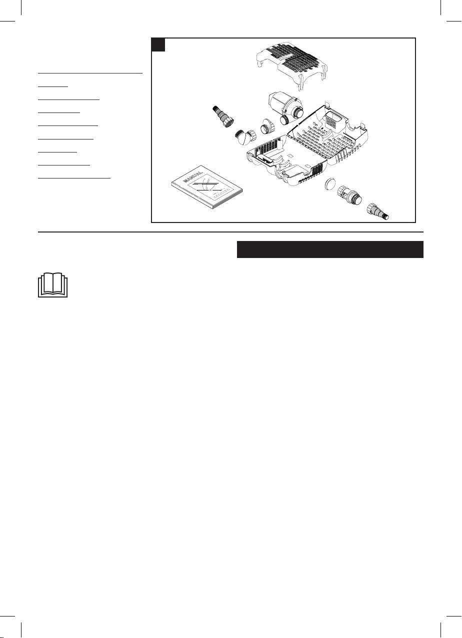
Check all contents are present
before installation.
A. Small Fish Protection Insert
B. Pump
C. Outlet adaptor
D. Ball Joint
E. Hosetail & Nut
F. Strainer Cage
G. End Cap
H. Flow Control
I. Instruction Manual
1
A
B
E
C
F
D
I
G
H
E
Thank you for choosing a Hozelock quality product.
You can be assured of many years of reliable service
from this product.
THIS APPLIANCE IS FOR HOUSEHOLD
USE.
READ THESE INSTRUCTIONS CAREFULLY
BE FO RE ATTEMPTI NG INSTA LL ATION.
FAILURE TO OBSERVE THE FOLLOWING NOTICES
MAY RESULT IN INJURY, PRODUCT DAMAGE OR
LOSS OF FISH.
KEEP THESE INSTRUCTIONS FOR FUTURE
REFERENCE.
YOU CAN ALSO DOWNLOAD THESE
INSTRUCTIONS AT http://www.hozelock.com/
customer-service/instruction-leaflets.html.
This Hozelock Cyprio Aquaforce pump is electrically
operated and is designed to pump solid particles
up to 10mm in diameter with minimal prestrainer
maintenance. These types of pumps are particularly
suitable for pumping water to external filters or for
use in high flow waterfalls or watercourse applications
where low maintenance is important. The pump does
not use oil or grease for lubrication and can be used
safely in ponds containing fish or plants. The motor
consists of a sealed stator and water-cooled rotor. All
electrical components are isolated from the water.
ATTENTION
AUTOMATIC CUT-OUT
To help ensure your pump’s long life and to prevent
damage, it is fitted with automatic thermal overload
protection. This switches off the pump if it overheats.
If this occurs, switch off the power at the mains supply
to the pump. Check for the cause. Usually it will be
debris blocking the inlets of the pump or obstructing
the impeller. Remove the obstruction and wait for the
pump to cool down. Then switch on the pump again.
General Safety Guidelines
1. This pump has been designed for the use with
ponds only. Only use this pump for the operation
of pond filter systems, water displays, waterfalls
etc. Do not use this pump for any other use (i.e. do
not use this pump in swimming pools, bathrooms,
central heating systems etc). Using the product
for any other application may result in injury or
product damage.
2. Important - This appliance must only be used by
a responsible adult who is capable of using the
appliance in a safe way and who understands the
hazards involved. Use and store this appliance
out of reach of children and persons with reduced
physical, sensory, or mental capabilities.
3. WARNING: Always unplug or disconnect all
appliances in the pond from the electricity supply
before putting your hands in the water whilst
equipment is being installed, repaired, maintained
or handled. Never immerse the terminal end of
the cable in water.
4. Never use the mains supply cable to lift the pump,
as this may cause damage. We recommend fitting
a lifting cord to the handle on the strainer cage
when the pump is installed in deep water.
5. Do not operate or leave the pump in freezing
conditions.
6. Protect the pump from direct sunlight. Direct
sunlight may overheat the motor.
7. Never allow the pump to run dry.
8. Do not operate this pump without the strainer
cage properly attached. Using the pump without
the strainer cage may invalidate your guarantee.
9. ATTENT ION: This product is not suitable for water
temperatures above 35ºC.

10. AT TEN TION : Do not operate this product if the
mains supply cable or the motor has become
damaged in any way. The supply cable cannot
be replaced as it is permanently encased in the
motor housing and should therefore be disposed of
according to local regulations.
11. If you live in a hard water area (water with high
calcium or limescale content), the pump, rotor
assembly and inside of motor should be cleaned at
regular intervals (See MAINTENANCE).
12. Only use accessories which have been designed
for use with this product. The use of any other
accessories may invalidate your guarantee.
13. This pump is not suitable for use with salt or sea
water.
14. For the maximum total head of these pumps,
please refer to the table at the end of these
instructions.
Installing this product in the garden is classed as
‘notifiable’ in the revised Building Regulations for
England and Wales. The Regulations require you to tell
your local authority building control department that
you intend to install this product before installation.
Your local authority will let you know how you can get
your installation approved.
Electrical Connections
1. WARNING: Always unplug or disconnect all
appliances in the pond from the electricity supply
before putting your hands in the water whilst
equipment is being installed, repaired, maintained
or handled.
2. Check that the voltage marked on the unit
corresponds to the mains supply.
3. The pump is supplied with 10m of 3 core electric
cable which is permanently connected and sealed
to the motor.
The supply cable cannot be replaced. If the cable
is damaged, the pump should be discarded.
This product is designed to be permanently
wired to the mains supply in a dry weatherproof
enclosure through a Double-Pole Switched Fused
Spur - (Disconnector) to BS 3676 – with a minimum
contact gap of 3mm in each pole. Fitted with a 3
or 5 Amp fuse. The installation must conform to
the National and Local wiring regulations which
could include the use of plastic or metal conduit to
protect the cable.
4. A 10mA or 30mA Residual Current Device (RCD)
must be fitted to the mains supply.
5. WARNING: This appliance must be earthed and it
is essential that the connections are made using
the following code;
Brown – Live
Blue – Neutral
Green/Yellow – Earth
The BROWN lead should be connected to the
LIVE terminal which may be marked with an ‘L’ or
coloured brown or red.
The BLUE lead should be connected to the
NEUTRAL terminal which may be marked with an
‘N’ or coloured blue or black.
The GREEN/YELLOW lead should be connected to
the EARTH terminal which may be marked with an
‘E’ ( ) or coloured green or green/yellow.
6. If an extension cable is required, this should be
connected to the end of the pump cable using a
weatherproof cable connector.
The joint must be positioned in a suitable dry
housing. The extension cable should be of 3 core
0.75mm2 Polychloroprene rubber insulated cable
(ref: HO5 RN-F) and permanently wired to the
mains supply with a 3 or 5 Amp fuse.
7. The pump cable (and extension cable) should
be positioned and adequately protected against
damage especially where contact with gardening
equipment, (lawn mowers, forks etc..) children and
domestic animals may occur.
8. Consult a qualified electrician or local authority if
in any doubt about wiring to the mains supply.
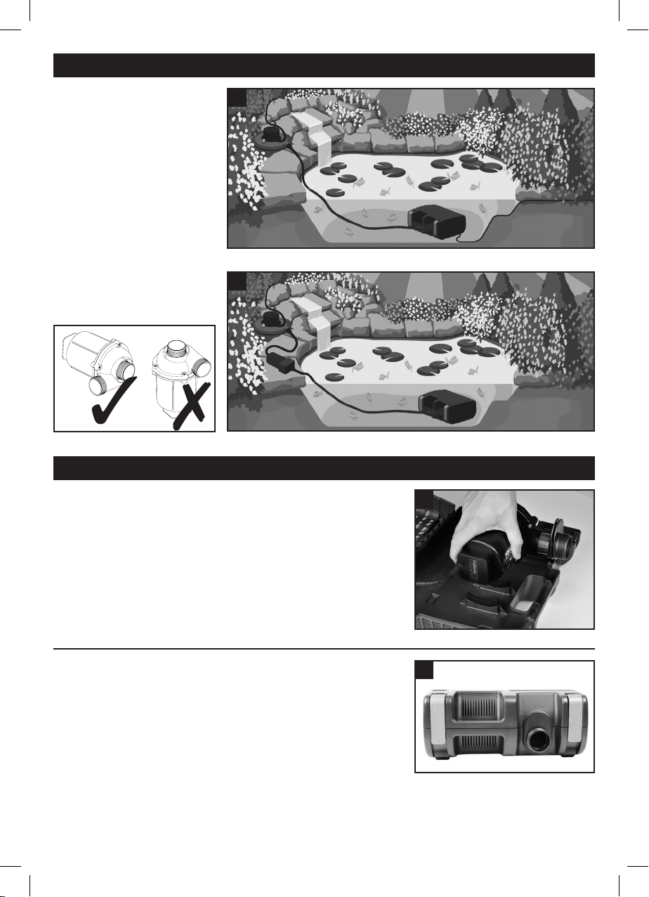
NOTE: When running
amphibiously, the dry sited
pump MUST be positioned
horizontally, as shown.
Typical Installation
2
Most common Aquaforce set up
3
Amphibious operation
Pump Assembly & Installation
- Submerged Operation
ASSEMBLY
1. Open the clips at either end
of the strainer cage (Fig 1 – F)
and open the cage.
2. Remove the Small fish
protection insert (Fig 1 – A).
3. Remove & unpack the ball
joint, hosetails & Flow control
(Fig 1–D,E & H).
Note:
The adaptor should be orientated
with the outlet at the bottom of
the cage (fig 5).
4. Remove the mains supply
cable and unwind.
5. Ensure that the outlet of the
pump is secured to the outlet
adaptor (Fig 1 – C). Locate
the pump onto its mounting
area ensuring that the adaptor
piece slots into the location
ribs in the front of the lower
cage (Fig 4).
4
5
 Loading...