

Hoyt Electrical Instrument Works, Inc. Alpha 41A Plus, Alpha 42A Plus, Alpha 40A Plus Operating Manual
Alpha 40A+/41A+/42A+
Operating Manual
Rev. 01_09/2015
2-60-006-00-00614


Section Contents
Installation & Operating Instructions
DIGITAL MULTIFUNCTION INSTRUMENT
Programmable Multi-function Energy Meter
1. Introduction
2. Measurement Reading Screens
3. Programming
3.1 Password Protection
3.2 Menu selection
3.2.1 System Parameter selection screen
3.2.1.1 System Type
3.2.1.2 Potential Transformer Primary value
3.2.1.3 Potential Transformer Secondary value
3.2.1.4 Current Transformer Primary value
3.2.1.5 Current Transformer Secondary value
3.2.1.6 Demand Integration Time
3.2.1.7 Auto Scrolling
3.2.1.8 Low Current Noise Cutoff
3.2.1.9 No. of Poles Selection
3.2.1.10 Energy Output
3.2.1.11 Energy Digit Reset count
3.2.1.12 Energy Rate
3.2.2 Communication Parameter selection screen
3.2.2.1 Address Setting
3.2.2.2 RS 485 Baud rate
3.2.2.3 RS 485 Parity selection
3.2.3 Reset Parameter selection screen
3.2.3.1 Resetting Parameter
3.2.4.1.1.1.1 Assignment of Energy to Pulse
3.2.4.1.1.1 Pulse Output
3.2.4.1.1 Relay Output Selection menu
3.2.4 Output Option selection screen (menu)
3.2.4.1.1.1.2 Pulse Duration Selection
3

3.2.6 Quit screen
7. Run - Hour
8. On - Hour
9. Number of Interruption
Relay Output
10.
10.1 Pulse output
10.2 Limit Switch
Phasor Diagram
11.
12. Installation
EMC Installation Requirements12.1
12.2 Case Dimensions and Panel Cut-out
12.3
Wiring
12.4 Auxiliary Supply
12.5 Fusing
12.6 Earth / Ground Connections
13.
Connection Diagrams
14.
Optional Pluggable Module
15.
16.
Connection for Optional Pulse output / RS 485
3.2.4.1.1.1.3 Pulse Rate
3.2.4.1.1.2 Limit output
3.2.4.1.1.2.1 Assignment of Limit Output to Parameter
3.2.4.1.1.2.3 Trip point selection
3.2.4.1.1.2.4 Hysteresis selection
3.2.4.1.1.2.5 Energizing delay time
3.2.4.1.1.2.6 De-energizing delay time
3.2.5 User Assignable Features
3.2.5.1 Feature Selection Menu
3.2.5.1.1 Backlit
3.2.5.1.2 User Assignable Screens
4. Current Reversal screen
5. Phase Rotation Error screen
6. Phase Absent screen
4
5
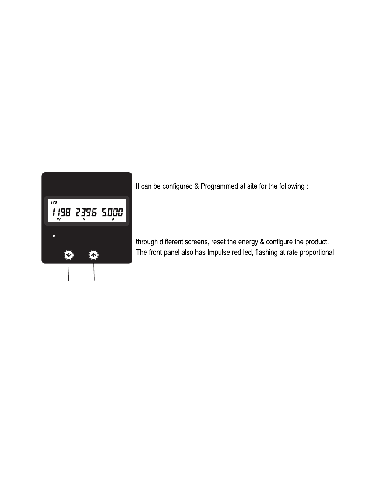
PT Primary, PT Secondary, CT Primary, CT Secondary 3 Phase 3W,
3 Phase 4W, 1 Phase 2W system.
The front panel has two push buttons using which the user can scroll
to measured power.
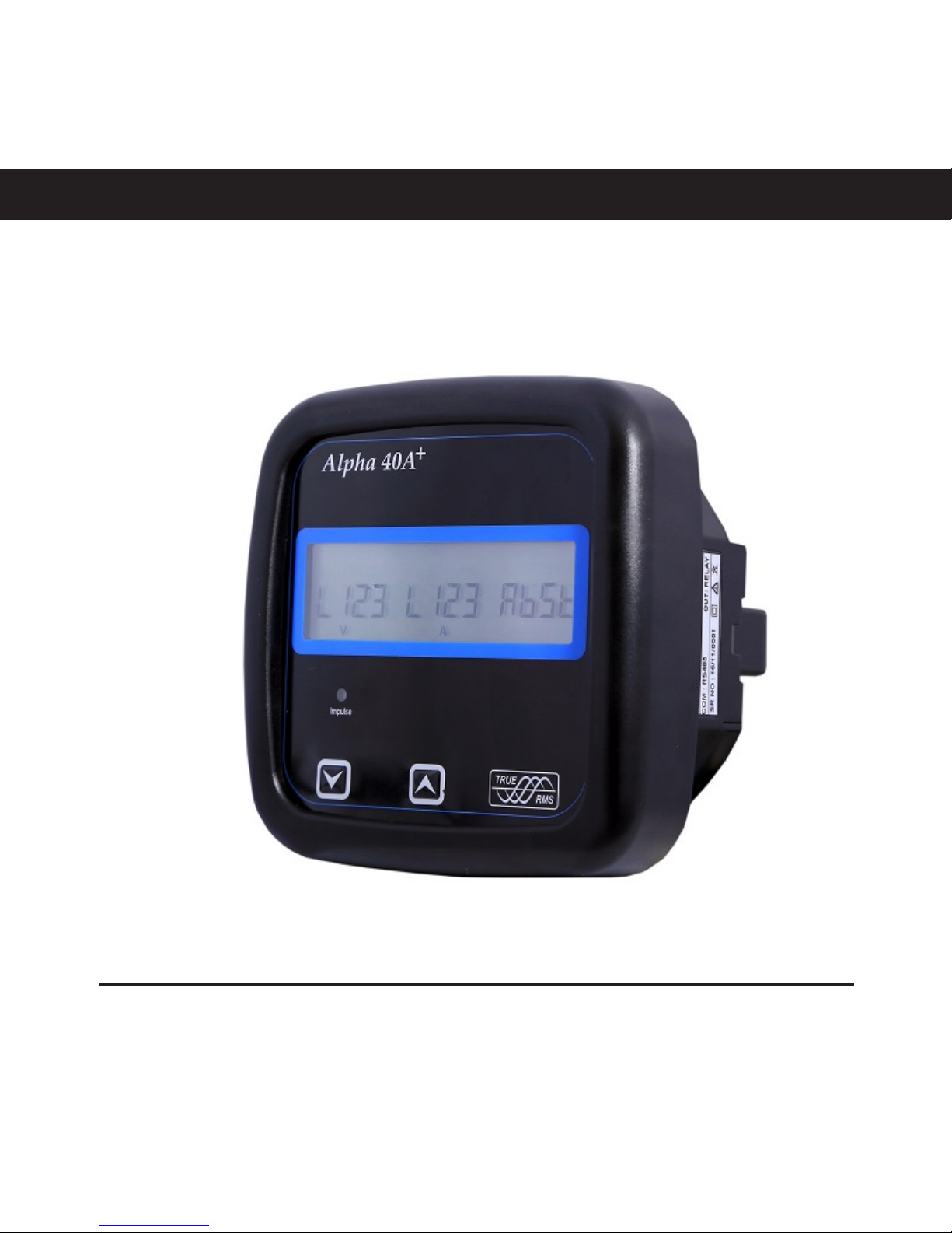
1. INTRODUCTION
The Multifunction Energy Meter is a panel mounted 114mm x 114mm ANSI round and 96 x 96mm
DIN Quadratic Digital Panel Meter, which measures important electrical parameters in 3 ph 4 wire
/ 3 wire / 1ph Network and replaces the multiple analog panel meters. It measures electrical
parameters like AC voltage, Current, Frequency, Power, Energy(Active / Reactive / Apparent), phase
angle, power factor & many more. The instrument integrates accurate measurement technology (All
Voltages & current measurements are True RMS upto 15th Harmonic) with LCD display with backlit.
UPDOWN
Impulse
Alpha 40A+
2. MEASUREMENT READING SCREENS
In normal operation, the user is presented with one of the measurement
reading screens out of several screens. These screens may be scrolled
through one at a time in incremental order by pressing the “UP key” and in
decremental order by pressing “DOWN key”.
6
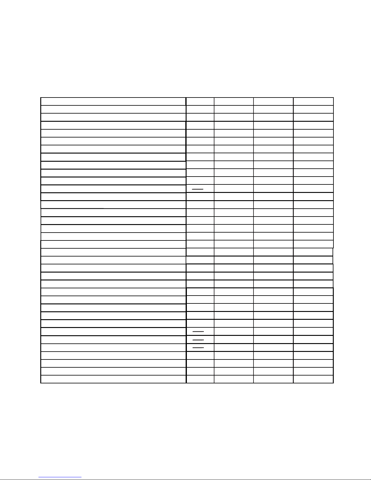
*Note: Units of these parameters will depend on “Energy Output”. (Refer section 3.2.1.10)
TABLE 1: Measured Parameters System Wise:
Voltage THD (System / Phase)
Current THD (System / Phase)
%
%
Measured Parameters
System Voltage
System Current
Frequency
Voltage VL1-N / 2-N / 3-N
Voltage VL1-L2 / L2-L3 / L3-L1
Current L1 / L2 / L3
Active Import Energy (9 Digit resolution)*
Units
Volts
Amps
Hz
Volts
Volts
Volts
Amps
kWh
kWh
Active Export Energy (9 Digit resolution)*
Active Power (System / Phase)
Reactive Power (System / Phase)
Apparent Power (System / Phase)
Power Factor (System / Phase)
Phase Angle (System / Phase)
kW
kVAr
kVA
Degree
kVArh
Capacitive Reactive Energy (9 Digit resolution)*
kVArh
Inductive Reactive Energy (9 Digit resolution)*
kVAh
Apparent Energy (9 Digit resolution)*
Neutral Current
Current Demand
kVA Demand
kW Import Demand
kW Export Demand
Max Current Demand
Max kVA Demand
Max kW Import Demand
Max kW Export Demand
Run Hour
On Hour
Number of Interruptions
Phase Rotation Error
kVA
kW
Amps
kVA
kW
kW
kW
Hours
Hours
Counts
Amps
3P 4W 3P 3W 1P 2W
only system only system
only system only system
only system only system
only system only system
only system only system
only system
only system
Min / Max System Voltage
Min / Max System Current
Volts
Amps
Phase Absent Indication
Current Reversal Indication
7
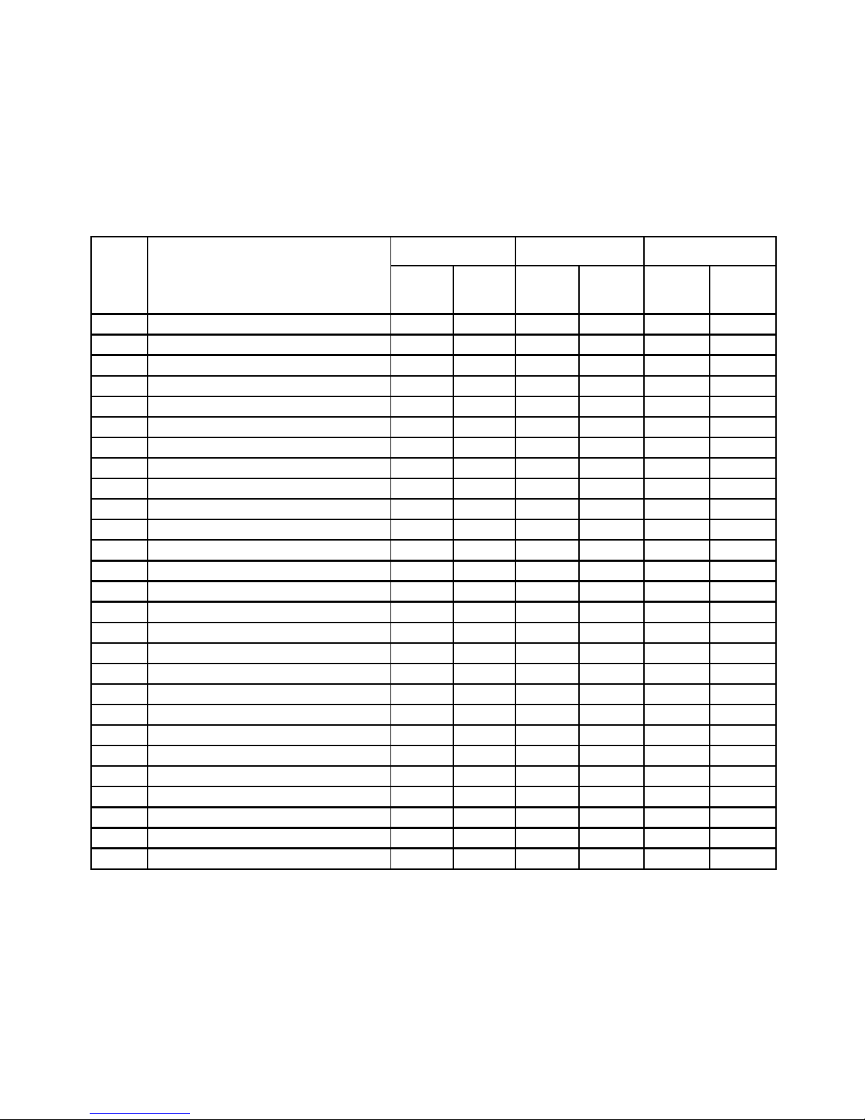
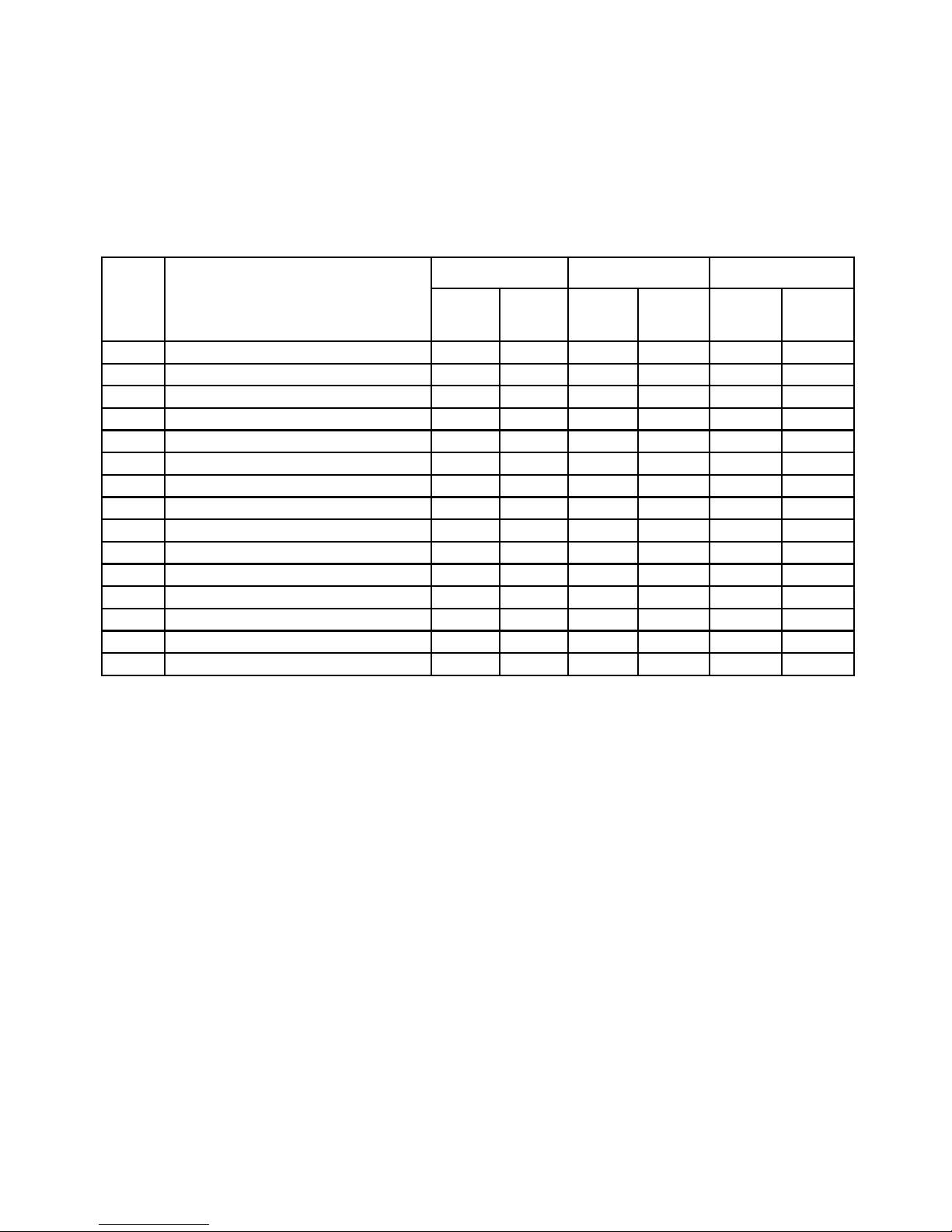
TABLE 2 : Measurement Screens (Model wise)
Screen
No.
Parameters
Alpha 42A+
Alpha 41A+
Alpha 40A+
On
Display
On
Modbus
On
Display
On
Modbus
On
Display
On
Modbus
1 Sys Power / Voltage / Current × √ √ √ √ √
√ √ √ √ √
√ √ √ √ √
4 Current × √ √ √ √ √
5 RPM / Frequency × √ √ √ √ √
6 Sys W / VA / Phase Angle × √ × √ √ √
7 Sys VAr / PF × √ only PF √ √ √
8 Active Energy Import √ √ √ √ √ √
9 Active Energy Export √ √ √ √ √ √
10 Capacitive Reactive Energy × √ × √ √ √
11 Inductive Reactive Energy × √ × √ √ √
12 Apparent Energy × √ × √ √ √
14 Min Sys Voltage & Current × √ × √ √ √
15 Max Sys Voltage & Current × √ × √ √ √
16 R Phase W/ VA / Phase Angle × √ only W √ √ √
17 Y Phase W/ VA / Phase Angle × √ only W √ √ √
18 B Phase W/ VA / Phase Angle × √ only W √ √ √
19 R Phase VAr / PF × √ only PF √ √ √
20 Y Phase VAr / PF × √ only PF √ √ √
21 B Phase VAr / PF × √ only PF √ √ √
22 W IMP / VA / Current Demand × √ × √ √ √
23 Max W IMP / VA / Current Demand × √ × √ √ √
24 W EXP / VA / Current Demand × √ × √ √ √
25 Max W EXP / VA / Current Demand × √ × √ √ √
26 Per Phase Voltage THD × × × × √ √
27 Per Phase Current THD × × × × √ √
28 Sys Voltage / Current THD × × × × √ √
L-N Voltage ×
L-L Voltage ×
2
3
8
TABLE 2 : Continued...
√ Available on Display
× Not available on Display
Screen
No.
Alpha 42A+ Alpha 41A+ Alpha 40A+
On
Display
On
Modbus
On
Display
On
Modbus
On
Display
On
Modbus
29 Run Hour × √ √ √ √ √
30 On Hour × √ √ √ √ √
35 No of Interruptions × √ √ √ √ √
37 I neutral × √ × √ √ √
38 Old Active Import Energy × √ × √ √ √
39 Old Active Export Energy × √ × √ √ √
41 Old Reactive Capacitive Energy × √ × √ √ √
42 Old Reactive Inductive Energy × √ × √ √ √
43 Old Apparent Energy × √ × √ √ √
45 Old Run Hour × √ × √ √ √
46 Old On Hour × √ × √ √ √
51 Old No of Interruptions × √ × √ √ √
53 Current Reversal √ × √ × √ ×
54 Phase Rotation Error √ × √ × √ ×
55 Phase Absent √ × √ × √ ×
Parameters
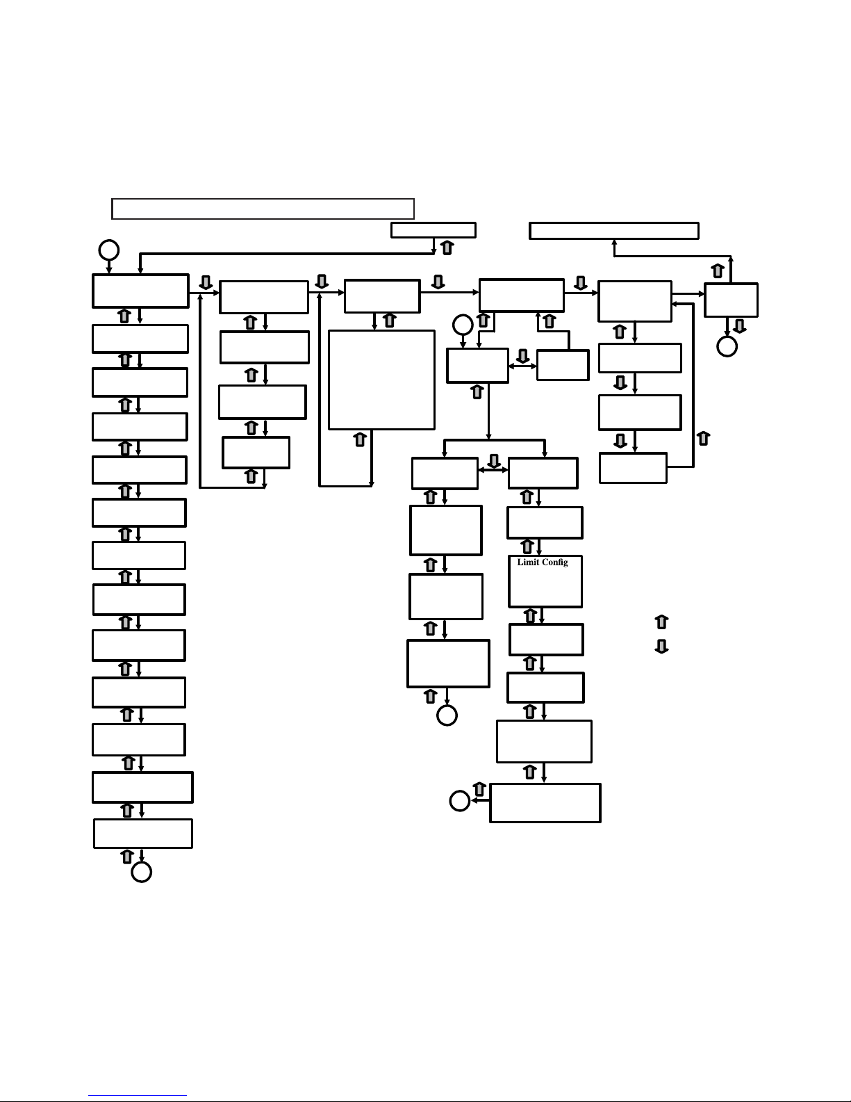
SEL (Select)
B
: UP KEY
: DOWN KEY
Out PArA
(Output Parameter)
rELY out
(Relay Output)
quit
(Exit Menu)
quit
(Exit Menu)
Lt
(Limit Output)
Para. Selection
(Acc. To Table)
.
Selection
(Hi-E,Hi-d,
Lo-E,Lo-d)
trip (Trip Point)
10% to 100%
HYS
(Hysterisis)
0.5% to 50%
En-d
(Energizing Delay time)
1s to 10s
dE-d
(De-energizing Delay time)
1s to 10s
PUL
(Pulse Output)
dur
(Pulse Duration)
60,100,200
rAt
(Pulse Divisor Rate)
1, 10, 100, 1000
.
Para Selection
(i-E, E-E, C-rE,
L-rE, A-E)
B
Exit
from setup Parameter to Main Display
rSEt
(Reset Parameter)
none (No Parameter),
ALL (All Parameters),
d (Demand),
E (Energy),
hi (Max values),
Lo (Min values),
Hr (Run Hour & On Hour),
Intr (No. of Interrupts)
Select any one option
using “Down” key.
Ser PArA
(Serial Comm.Parameter)
Addr
(Modbus Address)
br
(Baud Rate)
Pr
(Parity Bits)
codE (PassWord
)
SYS PArA
(System Parameter)
(Sec 3.2.1)
(Sec 3.2.2)
(Sec 3.2.3)
(Sec 3.2.4)
(Sec 3.2.4.1.1)
(Sec 3.2.4.1.1.1)
(Sec 3.2.4.1.1.1.1)
(Sec 3.2.4.1.1.1.2)
(Sec 3.2.4.1.1.1.3)
(Sec 3.2.4.1.1.2)
(Sec 3.2.4.1.1.2.1)
(Sec 3.2.4.1.1.2.2)
(Sec 3.2.4.1.1.2.3)
(Sec 3.2.4.1.1.2.4)
(Sec 3.2.4.1.1.2.5)
(Sec 3.2.4.1.1.2.6)
(Sec 3.2.2.1)
(Sec 3.2.2.2)
(Sec 3.2.2.3)
SYS
(System Type / Network)
UP
(PT Primary)
US
(PT Secondary)
AP
AS
dit
(Demand Integ. Time)
nC
(Noise Current Cut-off)
A
Auto
(Auto Scrolling)
(Sec 3.2.1.1)
(Sec 3.2.1.2)
(Sec 3.2.1.3)
(Sec 3.2.1.4)
(Sec 3.2.1.5)
(Sec 3.2.1.6)
(Sec 3.2.1.7)
(Sec 3.2.1.8)
Alpha 42A+/41A+/40A+ Setup Parameter Screen
(Sec 3.2.6)
(Sec 3.2.4)
Edrc
En.OP
(Energy Output)
(Sec 3.2.1.10)
(Sec 3.2.1.11)
(Energy digit reset count)
PoLE
(No. of poles selection)
(Sec 3.2.1.9)
A
Enrt
(Sec 3.2.1.12)
(Energy rate)
(CT Primary)
(CT Secondary)
USEr PArA
(User Assignable
bcLt
(Backlit On/Off)
(Sec 3.2.5)
(Sec 3.2.5.1.1)
Parameter)
(Sec 3.2.5.1.2)
Scrn
(User assignable
Screen feature)
quit
(Exit Menu)
(Sec 3.2.5)
A
B
9
3.1. Password Protection
Password protection can be enabled to
screens, by default password protection
Password protection is enabled by selecting
a password of 0000 disables the password
3. PROGRAMMING
The following sections comprise step by step procedures for configuring the Multifunction
Meter according to individual user requirements.
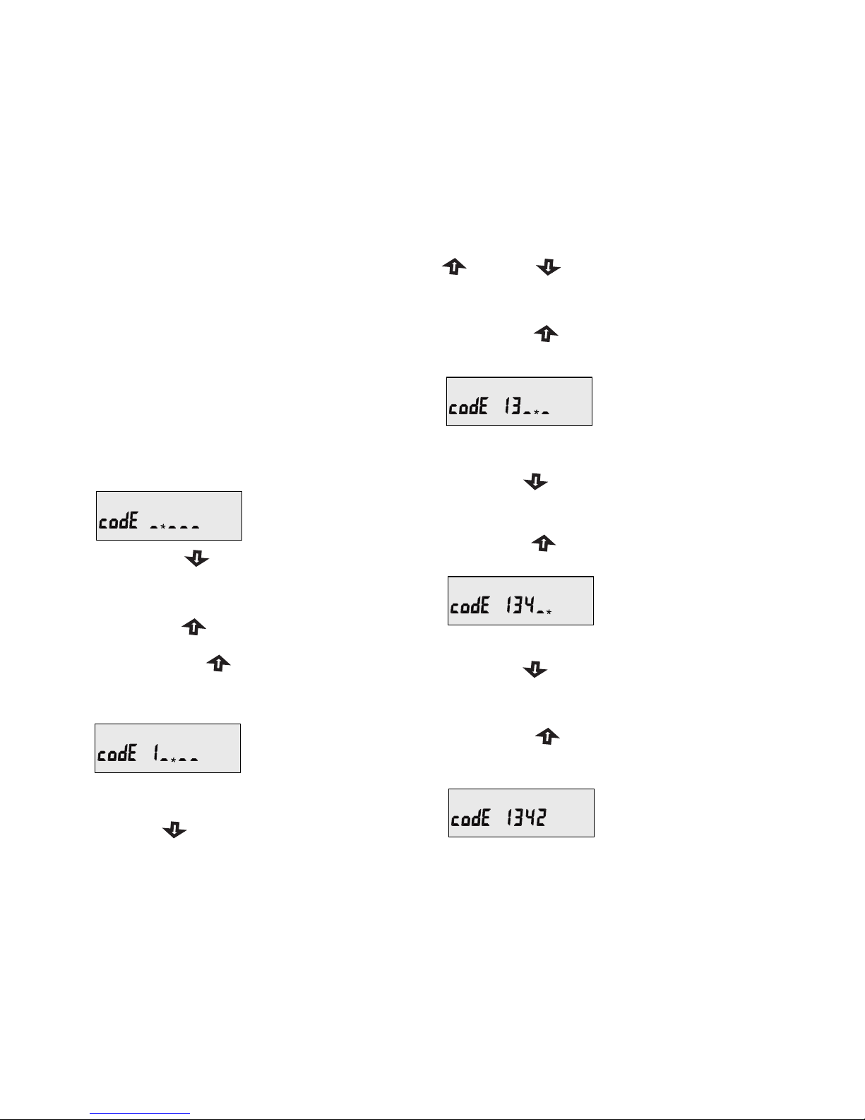
To access the set-up screens press and hold “ UP” and “ DOWN” keys simultaneously
for 5 seconds. This will take the User into the Password Protection Entry Stage (Section 3.1).
Enter Password, prompt
for first digit. (*Denotes
that decimal Point will
be flashing).
prevent unauthorised access to set-up
is not enabled.
a four digit number other than 0000, setting
protection.
Enter Password, first
digit entered, prompt for
second digit.(*Denotes
that decimal Point will
be flashing).
Press the “ ” key to scroll the value of
first digit from 0 through to 9, the value
will wrap from 9 round to 0.
Press the “ ” key to advance to next digit.
Enter Password, second
digit entered, prompt for
third digit. (* Denotes
that decimal point will
be flashing).
Press the “ ” key to advance to next digit.
Enter Password, third
digit entered, prompt
for fourth digit.
(*Denotes that decimal
point will be flashing).
In special case where the Password is “0000”
pressing the “ ” key when prompted for
the first digit will advance to “Password
confirmed” screen.
Press the “ ” key to advance to next digit.
Use the “ ” key to scroll the value of the
third digit from 0 through to 9, the value
will wrap from 9 round to 0.
Use the “ ” key to scroll the value of the
fourth digit from 0 through to 9, the value
will wrap from 9 round to 0.
Press the “ ” key to advance to
verification of the password.
Enter Password, fourth
digit entered, awaiting
verification of the
password.
Use the “ ” key to scroll the value of the
second Digit from 0 through to 9, the value
will wrap from 9 round to 0.
10
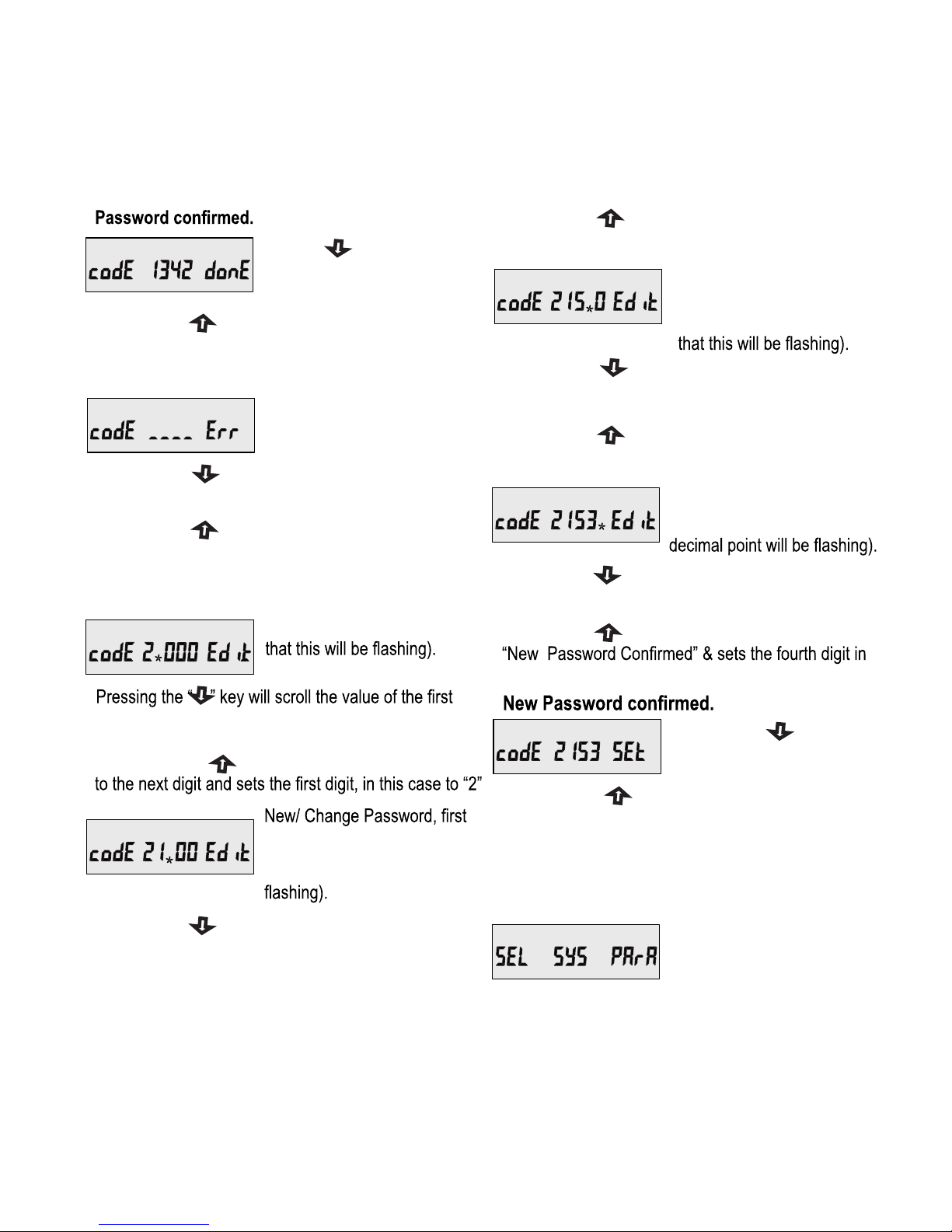
Pressing “ ” key will
advance to the “New / change
Password” entry stage.
Pressing the “ ” key to advance the operation
digit entered, prompting for
second digit. (*Decimal point
indicates that this will be
(* Decimal point indicates
New / Change Password
The unit has not accepted
the Password entered.
Password Incorrect.
Pressing the “ ” key will scroll the value of the
second digit from 0 through to 9, the value will
wrap from 9 round to 0.
New / Change Password,
second digit entered,
prompting for third digit.
(*decimal point indicates
Pressing the “ ” key will scroll the value of the
third digit from 0 through to 9, the value will wrap
from 9 round to 0.
New/ Change Password,
third digit entered, prompting
for fourth digit. (* denotes that
Pressing the “ ” key will return to the Enter
Password stage.
Pressing the “ ” key exits the Password menu
& returns operation to the measurement reading
mode.
Pressing the “ ” key will scroll the value of the
fourth digit from 0 through to 9, the value will wrap
from 9 round to 0.
Pressing the “ ” key to advance the operation to the
this case to “3”.
Pressing the “ ” key to advance the operation to the
next digit and sets the third digit, in this case to “5”
Pressing the “ ” key to advance the operation to the
next digit and sets the second digit, in this case to “1”
Pressing the “ ” key will advance to the Menu
selection screen. (See section 3.2).
digit from 0 through to 9, the value will wrap from
9 round to 0.
Pressing the “ ” key will
return to the “New/Change
Password”.
3.2 Menu selection.
3.2.1 System Parameter selection
screen
This screen is used to select
the different system Parameter
like “system type”,“CT
Pressing the “ ” key will advances to the Menu
selection screen. (see section 3.2).
11
Pressing the “ ” key allows the user to select &
Ratio”,“PT Ratio”,Pressing the “ ” key allows the
user to set Different system parameters.
(see section 3.2.1.1 to 3.2.1.12)
3.2.2 Communication
Parameter selection screen
This screen is used to select
the different communication
parameters like “Address
selection”,“RS485 Parity
selection”, “RS485 baud rate”.
This screen will allow the
user to access different
features like “Backlit”,“User
assignable screens”.
Pressing the “ ” key will advance to Communication
selection screen (see section 3.2.2)
Pressing the “ ” key allows the user to set different
Communication parameters.
(see section 3.2.2.1 to 3.2.2.3)
Pressing the “ ” key will advance to Reset
parameter Screen.(see section 3.2.3)
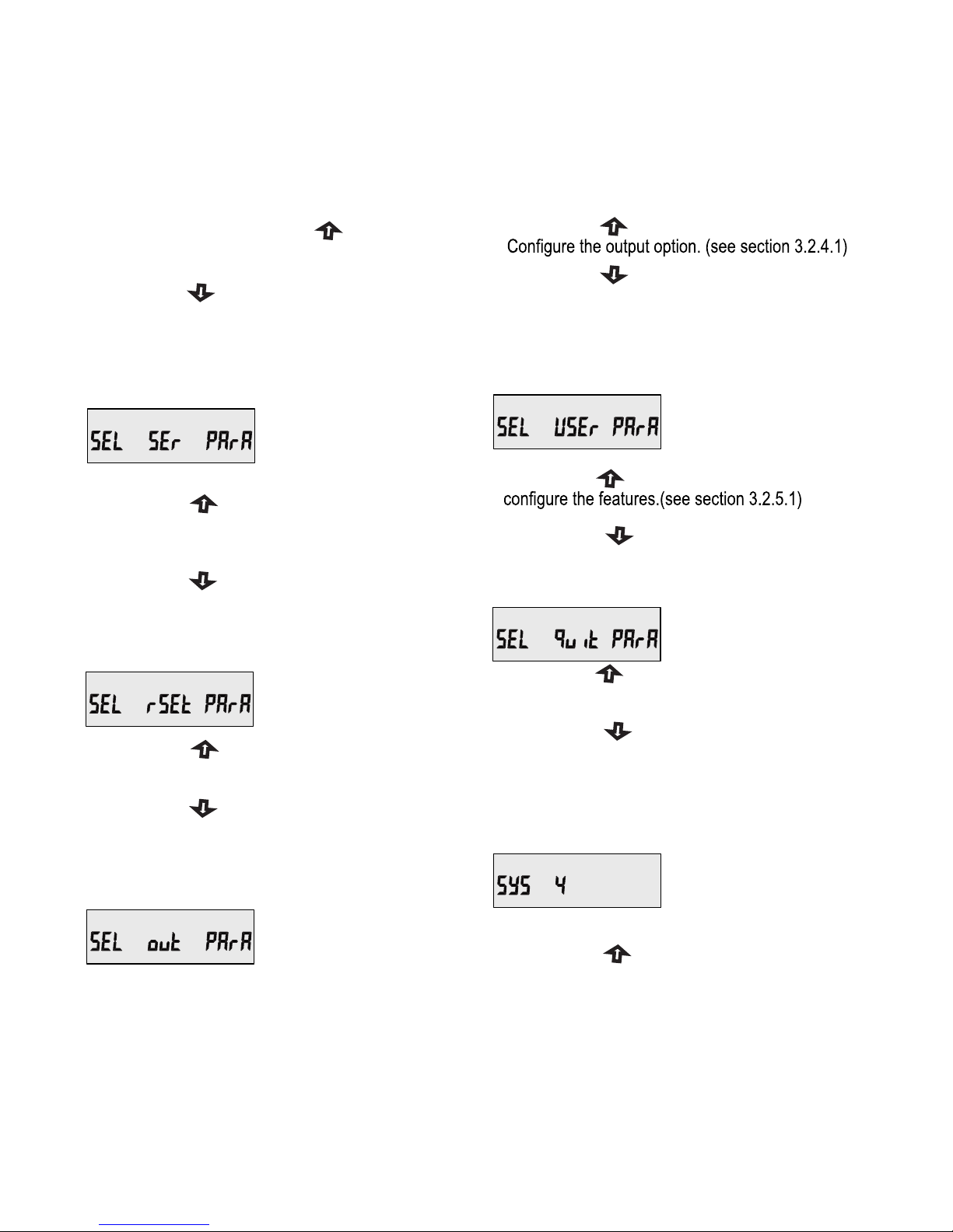
3.2.3 Reset Parameter
selection screen
This screen is used to Reset
the different parameters.
Pressing the “ ” key allows the user to Reset
different system parameters (see section 3.2.3.1)
Pressing the “ ” key will advance to Output
Option selection screen (see section 3.2.4).
3.2.4 Output Option selection
screen
This screen will allow the
user to select Output option
Like “Relay” Output.
Pressing the “ ” key will advance to User
Assignable Feature Selection screen.
(see section 3.2.5)
Pressing the “ ” key will allow the user to select &
Pressing the “ ” key will advance to Quit
screen. ( see section 3.2.6)
3.2.5 User Assignable Feature
Selection screen
3.2.1.1 System Type
3.2.1 System parameters Selection
This screen is used to set the
system type(only for 3 phase).
System type “3” for 3 phase
3 wire, “4” for 3 phase 4 wire
system & “1” for single phase
system.
3.2.6 Quit screen
This screen will allow the
user to Quit the Menu.
Pressing the “ ” key will allow the user to Quit
from menu & return to measurement screen.
Pressing the “ ” key will advance to System
Parameter Selection screen ( see section 3.2.1)
Pressing the “ ” key accepts the present value
and advances to the “Potential transformer primary
value Edit” menu. (see section 3.2.1.2)
12
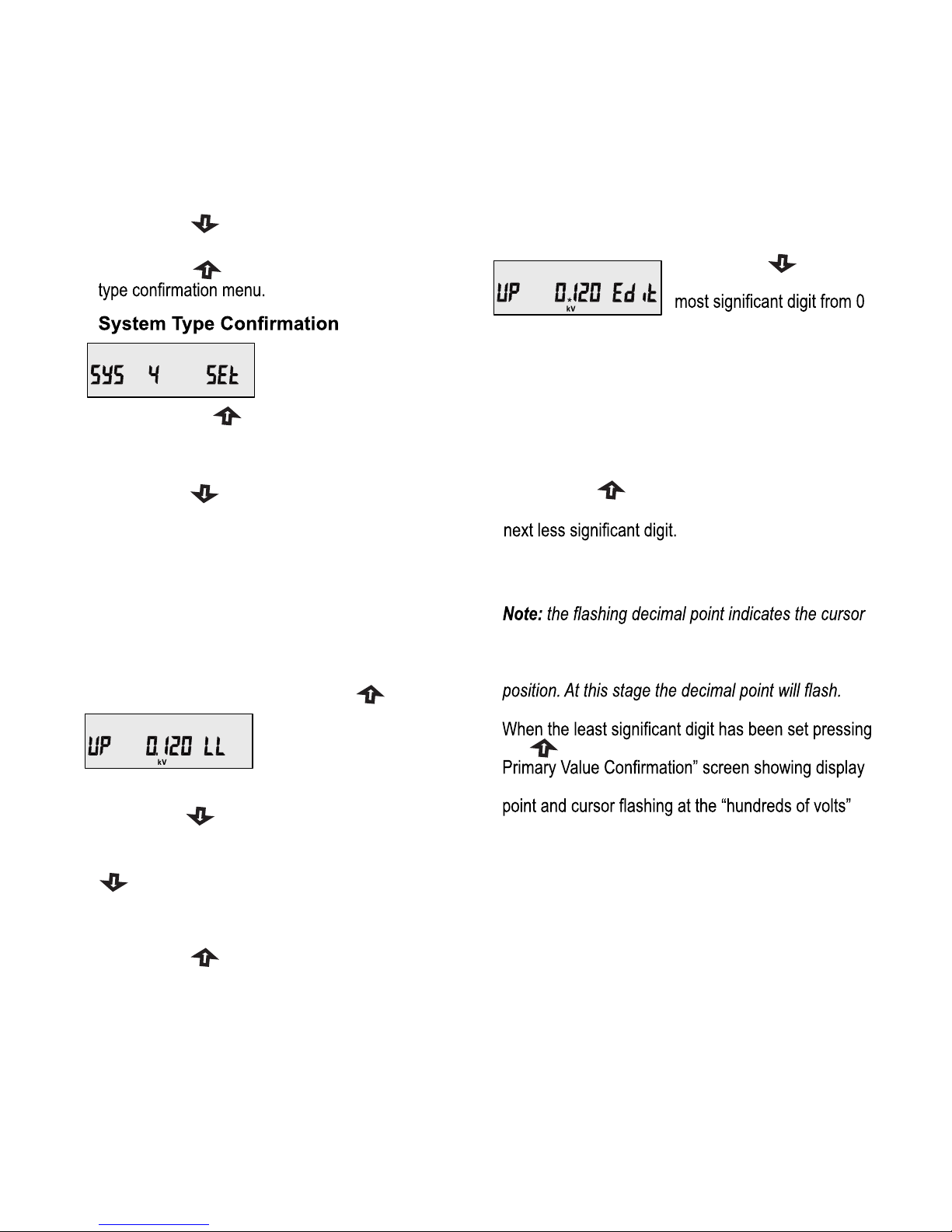
This screen will only appear
following the edit of system
type.
3.2.1.2 Potential Transformer
Primary Value
The nominal full scale voltage which will be displayed
as the Line to Line voltages for all system types.
The values displayed represent the voltage in
kilovolts (note “K” symbol).
Pressing the “ ” key accepts
the present value and
advances to the “potential
Transformer secondary Value
Edit” menu. (See Section
3.2.1.3)
Initially the “multiplier must be selected, pressing the
“ ” key will move the decimal point position to the
right until it reaches # # # #. after which it will return
to #. # # #.
Pressing the “ ” key accepts the present multiplier
(decimal point position) and advances to the
“potential Transformer primary Digit Edit” mode.
Note :
1. PT Values must be set as Line to Line
Voltage for Primary as Well as Secondary for all
system types (3P3W/3P4W/1P2W).
2. Default value is set as System Input Voltage.
Pressing the “ ” key sets the displayed
value and will advance to “Potential Transformer
Primary Value Edit” menu. (See section 3.2.1.2)
Pressing the “ ” key will return to the system type
edit stage.
NOTE: Default value is set to ‘4’ i.e. 3P 4W.
Pressing the “ ” key will enter the system type edit
mode & scroll through the values available.
Pressing the “ ” key advances to the system
Pressing the “ ” key will enter the “Potential
Transformer Primary Value Edit” mode.
The PT Primary value can be set from 100 VL- L to
1200 kVL-L. The value will be forced to 100 VL-L
if set less than 100.
position, a steady decimal point will be present to
identify the scaling of the number until the cursor
position coincides with the steady decimal point
the “ ” key will advance to the “Potential Transformer
of 0.120 kV i.e. 120 Volts indicating steady decimal
position.
presently displayed Potential Transformer Primary
Value together with the Current Transformer Primary
Value, previously set, would result in a maximum
system power of greater than 3000 MVA (1000 MVA
per phase) in which case the digit range will be
restricted.
Pressing the “ ” key accepts the present value at
the cursor position and advances the cursor to the
Pressing the “ ” key
will scroll the value of the
through to 9 unless the
Potential Transformer Primary Digit Edit
13
 Loading...