

Hoymiles MI-500, MI-600, MI-700, MI-1000, MI-1200 User Manual
1
MICROIVERTER
User Manual
(Model: MI-500 /MI-600 /MI-700)

2
User Manual
CONTENTS
INTRODUCTION ............................................................................................................................ 3
SAFETY ........................................................................................................................................... 4
SYMBOL ILLUSTRATION................................................................................................ 4
INSTALLATION WARNINGS .......................................................................................... 6
PREPARE FOR INSTALLING ...................................................................................................... 7
TRANSPORT AND INSPECT .......................................................................................... 7
CHECK INSTALLATION ENVIRONMENT .................................................................... 8
INSTALLATION POSITION.............................................................................................. 8
MOUNTING AND WIRING ............................................................................................................ 9
INSTALLING DIAGRAM ................................................................................................... 9
ASSEMBLY INSTRUCTION .......................................................................................... 11
Step 1. Install Microinverter ......................................................................................... 11
Step 2. Install AC Junction Box .................................................................................. 11
Step 3. Connect AC Cables of Microinverter ............................................................ 11
Step 4. Connect AC End Cable .................................................................................. 12
Step 5. Create an Installation Map ............................................................................. 12
Step 6. Connect PV Modules ...................................................................................... 13
Step 7. Energize the System ...................................................................................... 14
Step 8. System Monitoring Set Up ............................................................................. 14
TROUBLESHOOTING ................................................................................................................ 15
Status Indications and Error Reporting ..................................................................... 15
Troubleshoot an Inoperable Microinverter ................................................................ 15
MAINTENANCE GUIDE .............................................................................................................. 16
ROUTINE MAINTENANCE ............................................................................................ 16
STORAGE AND DISMANTLING ................................................................................... 17
APPENDIX .................................................................................................................................... 18
Grid Friendly Functions ................................................................................................ 18
TECHNICAL DATA .......................................................................................................... 19
INSTALLATION MAP ...................................................................................................... 21

3
INTRODUCTION
Thank you for using MI-500 /MI-600 /MI-700 Microinverter! This Microinverter system is
the world’s most technologically advanced inverter system with benefits of efficient,
flexible, safe and reliable for use in utility-interactive applications.
This system is composed of a group of Microinverters that convert direct current (DC) into
alternating current (AC) and feeds it into the electric grid. Different from systems that
photovoltaic modules are subdivided into strings and controlled by one or several
inverters, this system is built for the incorporation of a Microinverter for each photovoltaic
module. Each Microinverter works independently of the others to guarantee maximum
power of each photovoltaic module. This setup enables direct control over the production
of a single photovoltaic module, consequently improving the flexibility and reliability of the
system.
This manual contains important instructions for the MI-500 /MI-600 /MI-700 Microinverter
and must be read in its entirety before installing or commissioning the equipment. For
safety, only qualified technician, who has received training or has demonstrated skills can
install and maintain this Microinverter under the guide of this document.
Contact Information
Hoymiles Converter Technology Co. , Ltd.
No.18 Kangjing Road, Hangzhou, Zhejiang Province, China
Phone: +86-571-28056101
Fax: +86-571-28056137
http://www.hzconverter.com/cn/index.php
Hoymiles can provide commissioning. Please contact Hoymiles customer service at
086-0571-89775158. More information at website:
http://www.hzconverter.com/cn/index.php
4
SAFETY
IMPORTANT SAFETY INSTRUCTIONS!
PLEASE KEEP THIS INTRODUCTION IN A SAFE PLACE!
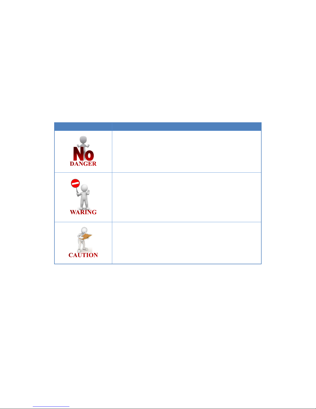
SYMBOL ILLUSTRATION
The safety symbols used in this manual are list below and illustrated in detail.
Symbol
Usage
Indicates a hazardous situation that can result in
deadly electric shock hazards, other serious
physical injury, or fire hazards.
Indicates directions which must be fully understood
and followed in entirety in order to avoid potential
safety hazards including equipment damage or
personal injury.
This points out that the described operation must
not be carried out. The reader should stop, use
caution and fully understand the operations
explained before proceeding.
5
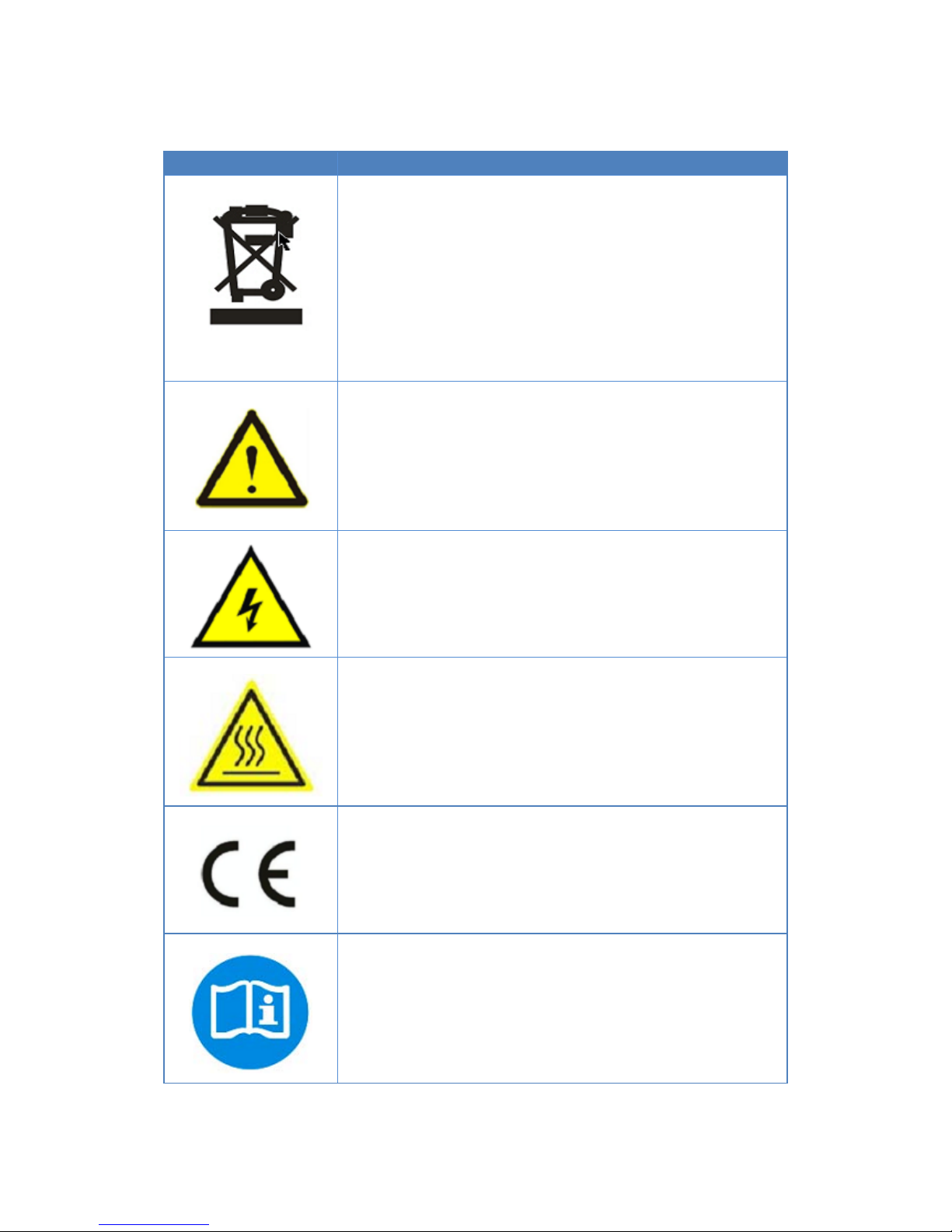
The symbols on the microinverter are list below and illustrated in detail.
Symbol
Usage
Treatment
To comply with European Directive 2002/96/EC on
waste Electrical and Electronic Equipment and its
implementation as national law, electrical equipment
that has reached the end of its life must be collected
separately and returned to an approved recycling
facility. Any device no longer required must be returned
to an authori zed dealer or approved collection and
recycling facility.
Caution
Do not come within 8 inches (20cm) of the
microinverter for any length of time while it is in
operation.
Danger of high voltages
Danger to life due to high voltage in the microinverter.
Beware of hot surface
The inverter can become hot during operation. Avoid
contact with metal surfaces during operation.
CE mark
The inverter complies with the requirements of the Low
Voltage Directive for the European Union.
Read manual first
Please read the installation manual first before
installation, operation and maintenance.
6
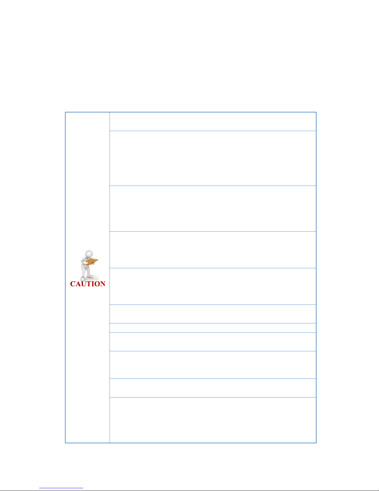
INSTALLATION WARNINGS
The MI-500 /MI-600 /MI-700 Microinverter is designed and tested according to
international safety requirements (IEC62109-1/-2, VDE4105, VDE0126, AS 4777.1 /.2&
AS 3000). However, certain safety precautions must be taken when installing and
operating this inverter. The installer must read and follow all instructions, cautions and
warnings in this installation manual
All operations including transport, installation, start-up and
maintenance, must be carried out by qualified, trained personnel.
Before installation, check the unit to ensure absence of any transport
or handling damage, which could affect insulation integrity or safety
clearances. Choose installation location carefully and adhere to
specified cooling requirements. Unauthorized removal of necessary
protections, improper use, incorrect installation and operation may
lead to serious safety and shock hazards or equipment damage.
Before connecting the Microinverter to the power distribution grid,
contact the local power distribution grid company to get appropriate
approvals. This connection must be made only by qualified technical
personnel. It is the responsibility of the installer to provide external
disconnect switches and Overcurrent Protection Devices (OCPD).
Only one photovoltaic module can be connected in the input of the
inverter. Do not connect batteries or other sources of power supply.
The inverter can be used only if all the technical characteristics are
observed and applied.
Do not install the equipment in adverse environment conditions such
as flammable, explosive, corrosive, extreme high or low temperature,
and humid. Do not use the equipment when the safety devices do not
work or disabled.
Use personal protective equipment, including gloves and eye
protection when working.
Inform the manufacturer about non-standard installation conditions.
Do not use the equipment if any operating anomalies are found. Avoid
temporary repairs.
All repairs should be carried out using only qualified spare parts,
which must be installed in accordance with their intended use and by
a licensed contractor or authorized Hoymiles service representative.
Liabilities arising from commercial components are delegated to their
respective manufacturers.
Anytime the inverter has been disconnected from the power network,
use extreme caution as some components can retain charge
sufficient to create a shock hazard. Prior to touching any part of the
inverter use care to ensure surfaces and equipment are at touch safe
temperatures and voltage potentials before proceeding.

7
Hoymiles accepts No liability for damage from incorrect or careless
operation
Electrical Installation & Maintenance shall be conducted by licensed
electrician and shall comply with Australia National Wiring Rules
PREPARE FOR INSTALLING
TRANSPORT AND INSPECT
Hoymiles packages and protects individual components using suitable means to make the
transport and subsequent handling easier. Transportation of the equipment, especially by
road, must be carried out by suitable ways for protecting the components (in particular, the
electronic components) from violent, shocks, humidity, vibration, etc. Please dispose the
packaging elements in appropriate ways to avoid unforeseen injury.
It is the customer’s responsibility to examine the condition of the components transported.
Once receiving the Microinverter, it is necessary to check the container for any external
damage and verify receipt of all items. Call the delivering carrier immediately if damage or
shortage is detected. If inspection reveals damage to the inverter, contact the supplier, or
authorized distributor for a repair/return determination and instructions regarding the
process.
 Loading...