

Hoymiles MI-1000, MI-1500, MI-1200 User Manual
MI
User Manual
MICROI
(Model: MI
-1000/MI-1200/MI-1500
NVERTER
-1000/MI-1200/MI-1500)
1

MI-1000/MI-1200/MI-1500
About Microinverter
This system is composed of a group of Microinverters that convert direct current (DC) into
alternating current (AC) and feeds it into the public grid. The system is designed for the
incorporation of one Microinverter for four photovoltaic modules. Each Microinverter works
independently that guarantees the maximum power generation of each photovoltaic
module. This setup enables user to control the production of a single photovoltaic module
directly, consequently improving the flexibility and reliability of the system.
About the manual
This manual contains important instructions for the MI-1000/MI-1200 Microinverter and
must be read in its entirety before installing or commissioning the equipment. For safety,
only qualified technician, who has received training or has demonstrated skills can install
and maintain this Microinverter under the guide of this document.
Other Information
Product information is subject to change without notice. User manual will be updated
frequently, please refer to Hoymiles official website at www.hoymiles.com for the latest
version.
2

MI-1000/MI-1200/MI-1500
Contents
1. Important Notes ..................................................................................................................................... 5
1.1 Product Range............................................................................................................................................. 5
1.2 Target Group ................................................................................................................................................ 5
1.3 Symbols Used .............................................................................................................................................. 5
2. About Safety ............................................................................................................................................ 6
2.1 Important Safety Instructions ................................................................................................................ 6
2.2 Explanation of Symbols ........................................................................................................................... 7
3. About Product ........................................................................................................................................ 7
3.1 About 4 in 1 unit .......................................................................................................................................... 7
3.2 Highlights ....................................................................................................................................................... 8
3.3 Terminals Introduction .............................................................................................................................. 8
3.4 Dimension...................................................................................................................................................... 8
4. Function .................................................................................................................................................... 9
4.1 Work Mode .................................................................................................................................................... 9
5. Installation ............................................................................................................................................ 10
5.1 Accessories ................................................................................................................................................ 10
5.2 Installation Precaution 图片 ................................................................................................................. 11
5.3 Space Distance Required 图片........................................................................................................... 11
5.4 Preparation ................................................................................................................................................. 12
5.5 Installation Steps ...................................................................................................................................... 13
6. Troubleshooting.................................................................................................................................. 17
7. Sample Wiring Diagram .................................................................................................................... 20
8. Decommissions .................................................................................................................................. 21
8.1 Decommissions ......................................................................................................................................... 21
8.2 Storage and Transportation ................................................................................................................. 21
8.3 Disposal ........................................................................................................................................................ 21
9. Technical Data ..................................................................................................................................... 22
9.1 DC Input ....................................................................................................................................................... 22
9.2 AC Ouput ..................................................................................................................................................... 22
9.3 Efficiency, Safety and Protection ....................................................................................................... 23
9.4 General Data .............................................................................................................................................. 23
Appendix 1: ............................................................................................................................................... 24
Installation Map........................................................................................................................................ 24
3
MI-1000/MI-1200/MI-1500
1. Important Notes
1.1 Product Range
This manual describes the assembly, installation, commissioning, maintenance
and failuresearch of the following model of Hoymiles Microinverter:
MI-1000
MI-1200
MI-1500
Note: “1000” means 1000W, “1200” means 1200W, “1500” means 1500W.
1.2 Target Group
This manual is only for qualified technician, who has been trained or has
demonstrated skills can install and maintain this Microinverter under the guide of
this document for safety purpose.
1.3 Symbols Used
The safety symbols in this user manual are show as below.
Symbol Usage
Indicates a hazardous situation that can result in deadly electric
shock hazards, other serious physical injury, or fire hazards.
Indicates directions which must be fully understood and followed in
entirety in order to avoid potential safety hazards including
equipment damage or personal injury.
Indicates this points out that the described operation must not be
carried out. The reader should stop, use caution and fully
understand the operations explained before proceeding.
4

MI-1000/MI-1200/MI-1500
2. About Safety
2.1 Important Safety Instructions
The MI-1000/MI-1200/MI-1500 Microinverter is designed and tested according to
international safety requirements (IEC62109-1/-2, VDE4105, VDE0126, AS
4777.1 /.2& AS 3000). However, certain safety precautions must be taken when
installing and operating this inverter. The installer must read and follow all
instructions, cautions and warnings in this installation manual.
All operations including transport, installation, start-up and maintenance, must be carried out by
qualified, trained personnel.
Before installation, check the unit to ensure free of any transport or handling damage, which could
affect insulation integrity or safety clearances. Choose installation location carefully and adhere to
specified cooling requirements. Unauthorized removal of necessary protections, improper use, incorrect
installation and operation may lead to serious safety and shock hazards or equipment damage.
Before connecting the Microinverter to the power distribution grid, contact the local power distribution
grid company to get appropriate approvals. This connection must be made only by qualified technical
personnel. It is the responsibility of the installer to provide external disconnect switches and Over
current Protection Devices (OCPD).
Only one photo voltaic module can be connected to one input of the inverter. Do not connect
batteries or other sources of power supply. The inverter can be used only if all the technical
characteristics are observed and applied.
Do not install the equipment in adverse environment conditions such as flammable, explosive,
corrosive, extreme high or low temperature, and humid. Do not use the equipment when the safety
devices do not work or disabled.
Use personal protective equipment, including gloves and eye protection during the installation.
Inform the manufacturer about non-standard installation conditions.
Do not use the equipment if any operating anomalies are found. Avoid temporary repairs.
All repairs should be carried out using only qualified spare parts, which must be installed in
accordance with their intended use and by a licensed contractor or authorized Hoymiles service
representative.
Liabilities arising from commercial components are delegated to their respective manufacturers.
Anytime the inverter has been disconnected from the public network, please be extremely caution as
some components can retain charge sufficient to create a shock hazard. Prior to touching any part of the
inverter please ensure surfaces and equipment are under touch safe temperatures and voltage
potentials before proceeding.
Hoymiles accepts No liability for damage from incorrect or improper operation
Electrical Installation & Maintenance shall be conducted by licensed electrician and shall comply with
Local Wiring Rules
5
MI-1000/MI-1200/MI-1500
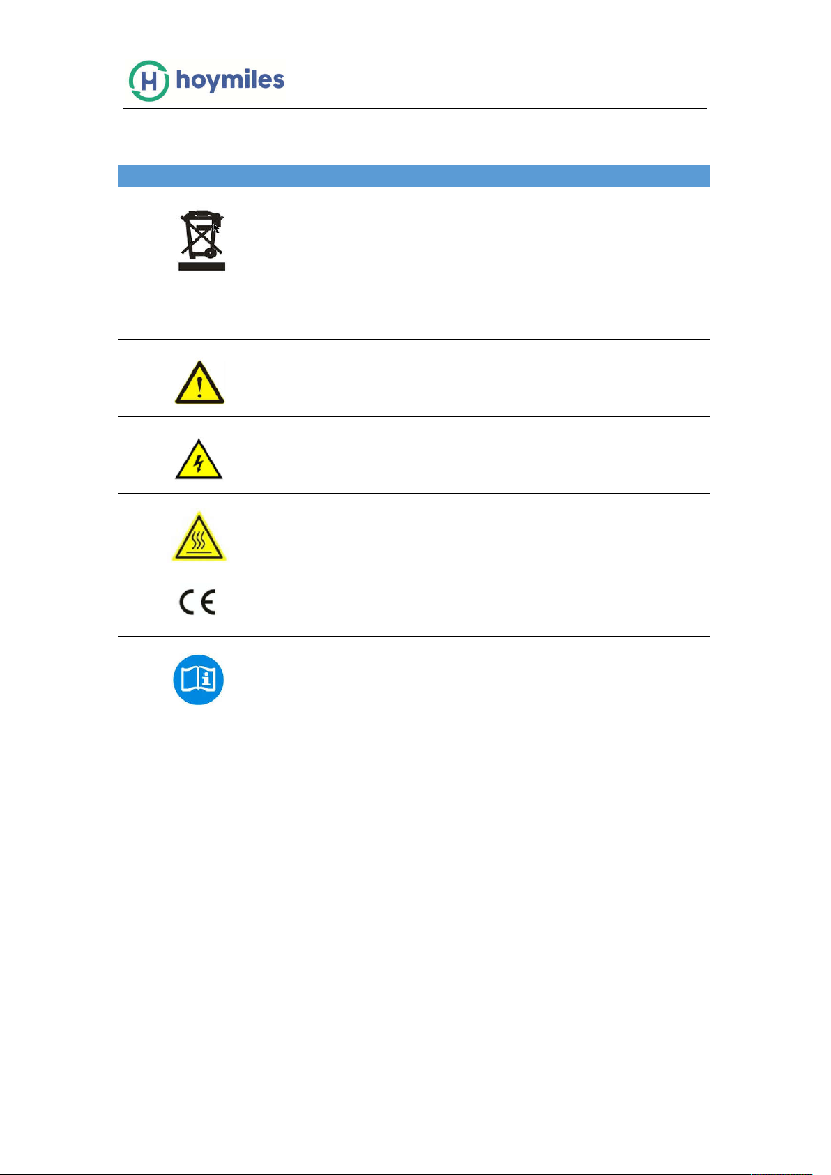
2.2 Explanation of Symbols
Symbol Usage
Treatment
To comply with European Directive 2002/96/EC on waste Electrical and
Electronic Equipment and its implementation as national law, electrical
equipment that has reached the end of its life must be collected separately
and returned to an approved recycling facility. Any device no longer
required must be returned to an authorized dealer or approved collection
and recycling facility.
Caution
Do not come within 8 inches (20cm) of the microinverter for any length of
time while it is in operation.
Danger of high voltages
Danger to life due to high voltage in the microinverter.
Beware of hot surface
The inverter can become hot during operation. Avoid contact with metal
surfaces during operation.
CE mark
The inverter complies with the requirements of the Low Voltage Directive
for the European Union.
Read manual first
Please read the installation manual first before installation, operation and
maintenance.
3. About Product
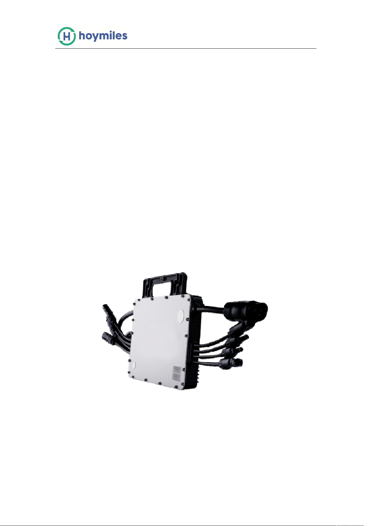
3.1 About 4 in 1 unit
“The world’s First Single-phase Microinverter” designed for 4 solar panels with dual
MPPTs with wide DC input operating voltage range(16-60V) and low start-up voltage
(22V only).
Hoymiles 4 in 1 Microinverter MI-1000/MI-1200/MI-1500 is “The Best PowerDensity
Microinverter” ever in solar industry with extremely light weight-only3.75KG including
integrated DC&AC cables;3-phase wiring is also easy to be configured by Hoymiles 4
in 1 Microinverter for MW size commercial PV power stations(one of the world’s
biggest Microinverter projects configured by Hoymiles Microinverter is 3.6MW).
6
MI-1000/MI-1200/MI-1500
3.2 Highlights
- Maximum output power up to 1000/1200/1500W; Adapted to 60 & 72 cells PV
panels.
- Peak efficiency 96.60%; CEC weighted efficiency 96.50%.
- Static MPPT efficiency 99.80%; Dynamic MPPT efficiency 99.76% in overcast
weather.
- High reliability: NEMA6 (IP67) enclosure; 6000V surge protection.
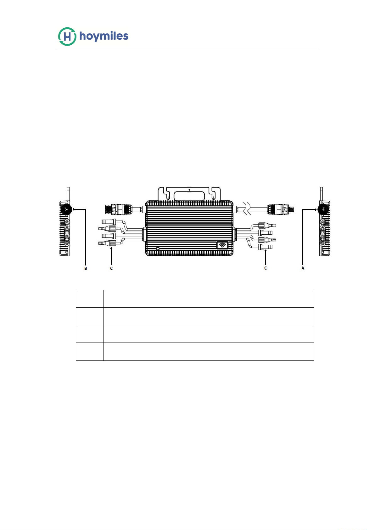
3.3 Terminals Introduction
Object
Description
A AC Connector (male)
B AC Connector (Female)
C DC Connectors
7
 Loading...