

Hoymiles DTU-MI-GPRS, DTU-MI User Manual
Version D-4-1.0 @2019

© 2019 Hoymiles Converter Technology Co., Ltd. All rights reserved. 2
DTU-MI-GPRS
Content
1. Important Safety Information ................................................................................................................................ 3
1.1 Read this First .................................................................................................................................................. 3
1.2 Safety Instructions ........................................................................................................................................... 3
1.3 User ................................................................................................................................................................... 3
1.4 Support and Contact Information .................................................................................................................. 3
1.5 Other Information ............................................................................................................................................. 4
2. Hoymiles Microinverter System ........................................................................................................................... 4
2.1 Microinverter .................................................................................................................................................... 4
2.2 DTU ................................................................................................................................................................... 4
2.3 Hoymiles Monitoring Server ........................................................................................................................... 4
3. Introduction to DTU Interface ............................................................................................................................... 5
3.1 DTU Screens .................................................................................................................................................... 5
3.2 DTU Local Interface ........................................................................................................................................ 5
3.3 DTU Home Interface ....................................................................................................................................... 6
3.4 DTU View Interface ......................................................................................................................................... 6
3.5 Configuration Interface ................................................................................................................................... 8
3.6 Device ID Interface .......................................................................................................................................... 8
4. DTU Installation.................................................................................................................................................... 10
4.1 System Capacity ............................................................................................................................................ 10
4.2 Basic Conditions Required........................................................................................................................... 10
4.3 Dimensions ..................................................................................................................................................... 11
4.4 System Installation Sequence ..................................................................................................................... 11
4.5 Install the DTU ............................................................................................................................................... 12
5. Complete Installation Map .................................................................................................................................. 16
6. Site creation on HMP .......................................................................................................................................... 16
7. Customer Login .................................................................................................................................................... 17
8. Browse the Web Station ..................................................................................................................................... 17
9. View Phone APP.................................................................................................................................................. 18
10. Troubleshooting ................................................................................................................................................. 18
11. Datasheet ........................................................................................................................................................... 19

© 2019 Hoymiles Converter Technology Co., Ltd. All rights reserved. 3
DTU-MI-GPRS
1. Important Safety Information
1.1 Read this First
This manual includes important instructions for installing and maintaining the Hoymiles Data
Transfer Unit (DTU-MI-GPRS).
1.2 Safety Instructions
Note that only professionals can install or replace DTU.
Do not try to repair DTU without Hoymiles’ approval. If DTU is damaged, please send the DTU
back to your installer for repairing/replacing. Disassembling DTU without Hoymiles’ approval will
invalidate remaining of the warranty period.
Please read all instructions and warnings on the technical specifications carefully.
Do not use Hoymiles products in a way that is not suggested by manufacture. If doing so, it
may cause death or injury to persons or damage to equipment.
1.3 User
This manual is only for professional installation and maintenance personnel to use.
1.4 Support and Contact Information
If you have technical queries concerning our products, please contact your system’s installer.
If further support is required, please contact Hoymiles’ support at this link.
www.hoymiles.com
Hoymiles’ customer service center: service@hoymiles.com
Symbol
Usage
Indicate a hazardous situation that can result in deadly electric shock hazards,
other physical severe injuries, or fire hazards.
Indicate directions that must be fully understood and followed in entirety to avoid
potential safety hazards, including equipment damage or personal injury.
Indicate that the described operation must not be carried out. The reader should
stop, use caution, and fully understand the processes explained before
proceeding.

© 2019 Hoymiles Converter Technology Co., Ltd. All rights reserved. 4
DTU-MI-GPRS
1.5 Other Information
Product information is subject to change without notice. The user manual will be updated
frequently, and please refer to Hoymiles official website at www.hoymiles.com for the latest
version.
2. Hoymiles Microinverter System
2.1 Microinverter
It converts the DC output of solar modules into grid-compliant AC power. It sends the output
information of PV panels and the operation data of the microinverters to the DTU, which is the
hardware basis of the panel-level monitoring.
With conversion efficiency up to 96.7% and MPPT efficiency up to 99.9%, Hoymiles
microinverters rank into the first class of the world’s Microinverter industry.
2.2 DTU
The DTU is the critical component in Hoymiles microinverter system. It works as the
communication gateway, which operates between the Hoymiles microinverters and the
Hoymiles Monitoring Server. The DTU communicates with the microinverter wirelessly via 2.4G
RF, collecting the operation data of the system. Meanwhile, the DTU connects to the Internet
via router and communicates with Hoymiles Monitoring Server. The microinverter system
operation data will be uploaded to Hoymiles Monitoring Server via DTU.
2.3 Hoymiles Monitoring Server
It collects the operation data and status of the microinverters in the system and provides the
module-level monitoring for the users and maintenance staff.
The following diagram shows the Hoymiles Microinverter system.
© 2019 Hoymiles Converter Technology Co., Ltd. All rights reserved. 5
DTU-MI-GPRS
3. Introduction to DTU Interface
3.1 DTU Screens
When the DTU completes the start-up process and obtains the IP address, the DTU will start
to operate. During operating, the LCD displays the primary system operation status and
indicates two different pages of info alternately shown below (screens 1 and 2 will appear once
internet configuration completed).
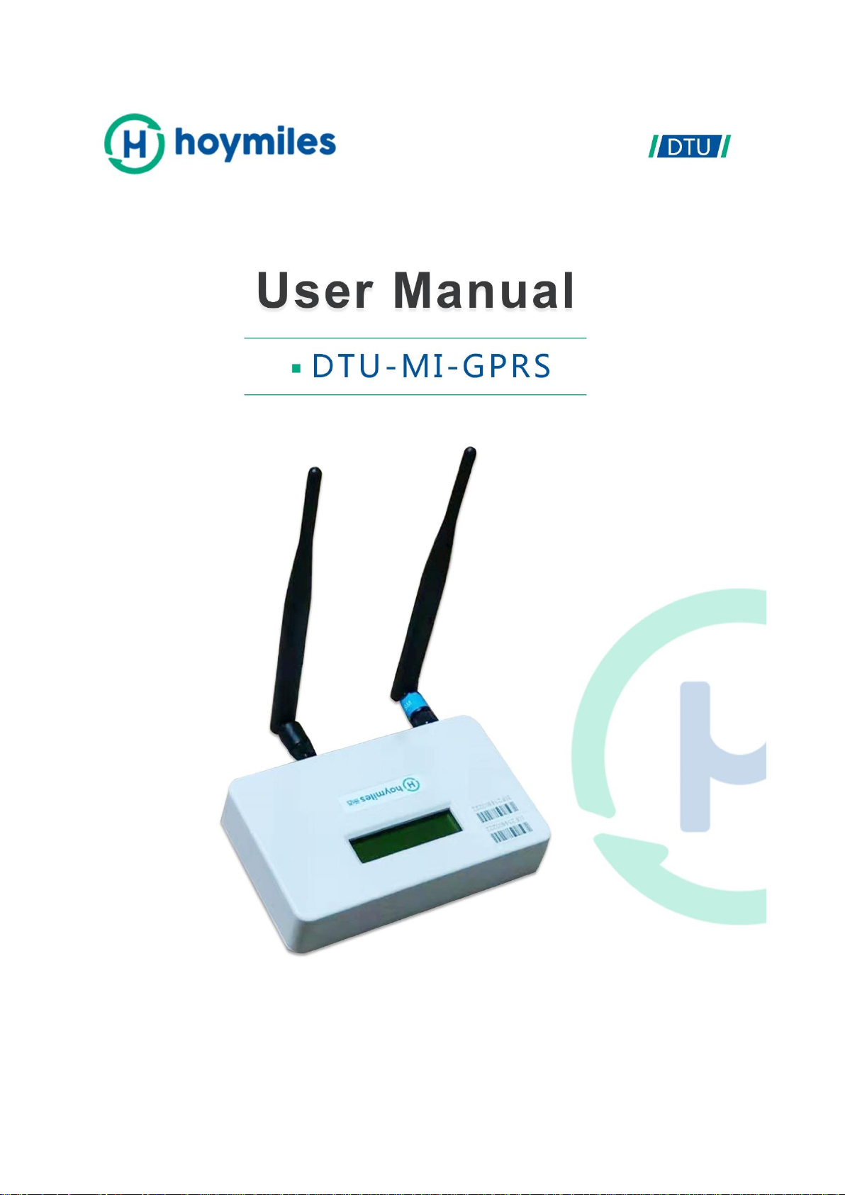
The data indicates:
Page 1:
(1) Web connection information: “YC” means that the DTU connects to the Internet. If it is
“NC”, the DTU does not connect to the Internet.
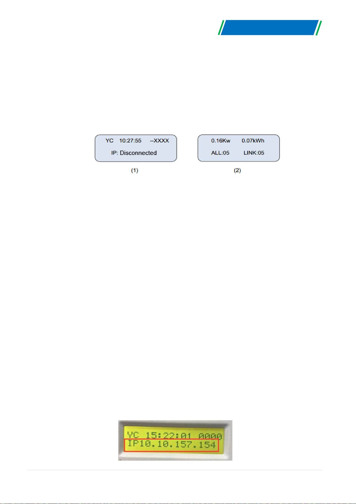
(2) Time, e.g. 10:27:55.
(3) --XXXX indicates the ID of the current search.
(4) Local IP address, e.g.192.168.1. XXX.
Page 2:
(5) It indicates data on the real-time output power in kilowatts, e.g., 0.16kW.
(6) It indicates data on today’s output energy of the system in kWh, e.g., 0.07kWh.
(7) The total number of microinverters in this system, e.g., ALL: 05.
(8) The number of microinverters usually communicating with DTU, e.g., LINK: 01.
(9) _XXXX, the first two indicate CSQ (IoT card connect Internet signal strength), the last
two indicate Internet transfer status.
3.2 DTU Local Interface
The DTU-MI has an embedded web server, which enables you to view the operation data,
status, and manage the devices and clear fault via browser locally. A computer will be needed
to connect to the same network with DTU, then open the DTU local interface in the browser by
entering the IP address shown on the LCD screen.

© 2019 Hoymiles Converter Technology Co., Ltd. All rights reserved. 6
DTU-MI-GPRS
3.3 DTU Home Interface
The home interface will be shown as the picture below once input the IP address into the
browser address bar. In the home interface, the left side displays the basic information of the
system, including Total Output Power, Total Energy, Today Energy, and CO2 Saved. On the
right side shows the operation data of each microinverter, including PV Voltage, Grid Voltage,
Grid Frequency, Grid Power, Today Energy, and Internal Temperature. On the upper side of
the page, it displays the total number of microinverters, connected microinverters, and
unconnected microinverters.
3.4 DTU View Interface
There are three options under “View” bottom: DTU Information; System Inventory; RF
Information.
 Loading...