

DTU-MI
User Manual
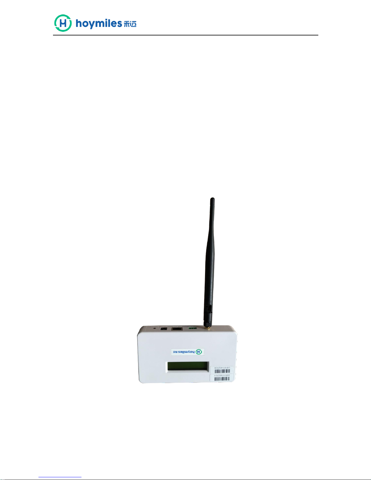
Data Transfer Unit
(model: DTU-MI)

DTU-MI
1 www.hoymiles.com
Table of contents
Important Safety Information ..................................................................................................... 2
Read this First .................................................................................................................... 2
Safety Instructions ............................................................................................................. 2
User ................................................................................................................................... 2
The Hoymiles Microinterver System ......................................................................................... 3
Basic DTU Operation ................................................................................................ ................ 4
LCD Screen Display at Start Up ......................................................................................... 4
Normal Operation............................................................................................................... 5
DTU Local Interface ........................................................................................................... 6
DTU Home Interface .......................................................................................................... 6
View Project ....................................................................................................................... 7
Ground Fault Reset ............................................................................................................ 9
Time Setting ....................................................................................................................... 9
Device ID Management ................................................................................................... 10
DTU Installation ................................ ................................................................ ...................... 12
System Capacity .............................................................................................................. 12
Basic Conditions Required ................................ ............................................................... 12
Installation Sequence ....................................................................................................... 13
Complete Installation Map ...................................................................................................... 18
Confirm Installation Successfully ............................................................................................ 18
Browse the Web Station ......................................................................................................... 19
View Phone APP .................................................................................................................... 19
Troubleshooting ...................................................................................................................... 20
LCD Screen Displays “NC” .............................................................................................. 20
The Link Number is less than Total Number of Microinverters .......................................... 20
Datasheet ........................................................................................................................ 21

DTU-MI
2 www.hoymiles.com
Important Safety Information
Read this First
This manual includes important instructions for installing and maintaining the Hoymiles data
transfer unit(DTU-MI).
Safety Instructions
Note that only professionals can install or replace DTU.
Don't try to repair DTU because it contains parts that are not available to users. If DTU is
damaged, please send the DTU back to our dealer for repair. Disassembling DTU privately will
invalidate the warranty period.
Please read all instructions and warnings on the technical specifications and the DTU carefully
User
This manual is only for professional installation and maintenance personnel to use.
Support and Contact Information
If you have technical queries concerning our products, please contact your system installer. If further
support is required, contact Hoymiles support at this link.
http://www.hoymiles.com
Hoymiles customer service center
Tel:+86-0571-8977515
Hoymiles Converter Technology Co. , Ltd.
No.18 Kangjing Road, Hangzhou, 310015, China
Tel: +86-571-28056101
E-mail:sales@hoymiles,com
DTU-MI
3 www.hoymiles.com
The Hoymiles Microinterver System
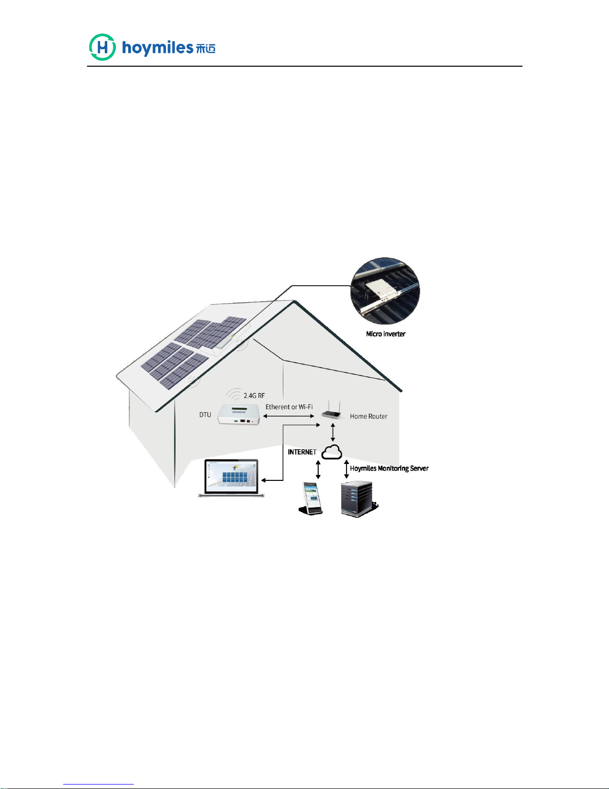
The DTU is the key component in Hoymiles microinverter system. It works as the communication
gateway, which operates between the Hoymiles microinverters and the Hoymiles Monitoring Server.
The DTU communicates with the microinverter wirelessly via 2.4 G RF, collecting the operation data
of the system. Meanwhile, the DTU connects to the Internet via router or GPRS and communicate
with Hoymiles Monitoring Server. The microinverter system operation data will be uploaded to
Hoymiles Monitoring Server via DTU.
The following diagram shows the DTU in the system.
Other Elements In the Hoymiles Microinverter System
The Microinverter: It converts the DC output of solar modules into grid-compliant AC power. It
sends the output information of PV panels and the operation data of the microinverters to the DTU,
which is the hardware basis of the panel-level monitoring.
With efficiency up to 96.7% and MPPT efficiency up to 99.9%, Hoymiles microinverters rank in the
first level around the world.
The Hoymiles Monitoring Server: It collects the operation data and status of the microinverters
in the system, and provides the panel-level monitoring for the users and maintenance staffs.
DTU-MI
4 www.hoymiles.com
Basic DTU Operation
LCD Screen Display at Start Up
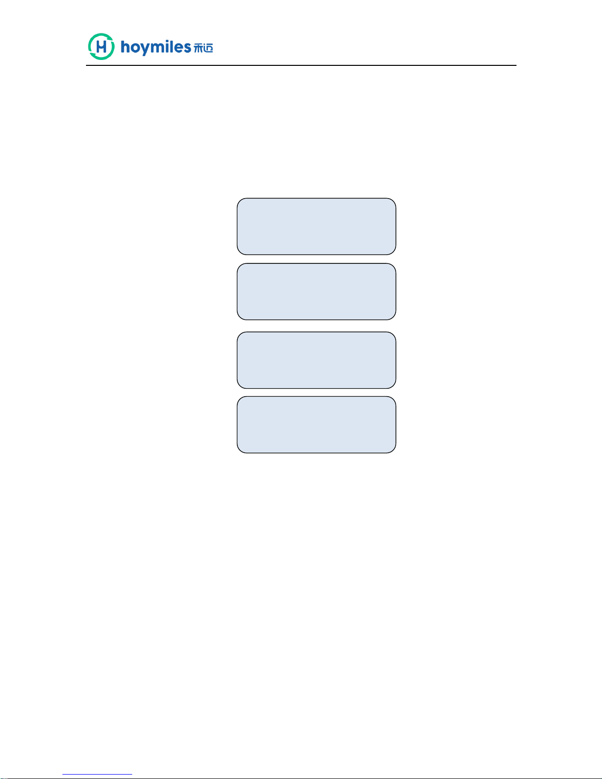
When the DTU starts up, it goes through the initial boot sequence. During this sequence, the DTU
LCD screen displays start-up progress as shown:
BOOT SYS setup
10:26:30
System setup…
10:27:55
ETH_BSP_Config
10:27:55
IP: 0.0.0.0

DTU-MI
5 www.hoymiles.com
Normal Operation
When the DTU completes the start up process and obtains the IP address, normal operation begins.
During the normal operation, the LCD screen displays the basic operation status of the system,
and the two screens shown as below alternate all the time.(screens 1 and 2 will appear when you
configure the Internet access).
(1) (2)
The data indicates:
(1) Web connection information: “YC”, this means the DTU is connected to the Internet. If it is
“NC”, the DTU is not connected to the Internet.
(2) Time, e.g. 10:27:55.
(3) Local IP address, e.g.192.168.1. XXX.
(4) Data of the real-time output power in watts, e.g.0.16kW.
(5) Data of the today’s output energy of the system in kWh, e.g. 0.07kWh.
(6) The total number of microinverters in this system, e.g. ALL: 05.
(7) The number of microinverters normally communicating with DTU, e.g. LINK: 01.
(8) _XXXX, the first two indicate CSQ (IOT card connect Internet signal strength), last two
indicate Internet transfer status.
(9) --XXXX, Indicates the ID of the current search.
YC 10:27:55 --XXXX
IP: 192.168.1.122
0.16Kw 0.07kWh
ALL:05 LINK:05
DTU-MI
6 www.hoymiles.com
DTU Local Interface
The DTU has an embedded web server, which enables you to view the operation data and status of
the system, manage the devices and clear fault locally via a browser. You need to get your
computer connected to the same network with DTU to open the DTU local interface in your browser
by entering the IP address shown on the LCD screen.
DTU Home Interface
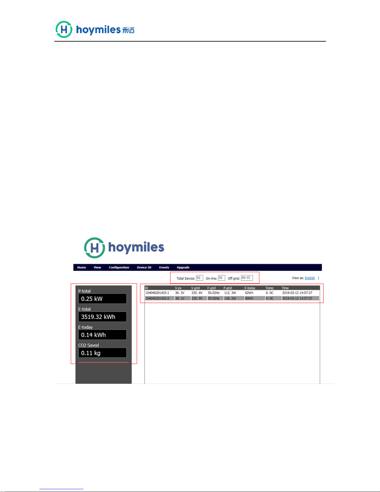
The home interface shown below will turn up first when you enter the IP address into the browser.
In the home interface, the left side displays the basic information of the system, including Total
Output Power, Total Energy, Today Energy and CO2 Saved. the middle form displays the operation
data of each microinverter, including PV Voltage, Grid Voltage, Grid Frequency, Grid Power, Today
Energy and Internal Temperature. The upward side displays the total number of microinverters, the
number of connected microinverters and the number of unconnected microinverters.

DTU-MI
7 www.hoymiles.com
View Project
Click “ View ”, appear three options.
(1) ViewDTU Information, access to the DTU basic information interface, which contains the
following information:

DTU-MI
8 www.hoymiles.com
a. DTU Information item include software version, hardware id code, manufacturing date and
upload server time intervals in turn. The upload time intervals can be changed according to the
requirements, usual default setting is 900.
b. The Network Information item is mainly the configuration Information related to the
network port, includes static IP and dynamic IP settings. Tick Enable DHCP when connect to a
router.
c. Client Set item include server address, server IP, server port.
Server address: data4.hoymiles.com, Factory settings
Server IP: 119.3.25.186, Factory settings
Dest Port: 10017, Factory settings
(2) ViewSystem Inventory, check the software and hardware version number of the microinverter
in the system. The display is in turn: microinterver ID, hardware version number, software versioning,
installation time and status.
(3) View RF Information, check the software and hardware version of the communication
module in the system. The display is in turn: communication module ID, hardware version software
version and status. The first line shows basic information of the DTU communication module.

DTU-MI
9 www.hoymiles.com
Ground Fault Reset
Click “ConfigurationGFDI Fault” to open ground fault manage interface. You can check whether
the microinverters have a ground fault or not. If the faults exist, click “Clear Fault”. If the problem
persists, please contact our technical support.
Time Setting
Click “ConfigurationDate/Time” to open the times setting interface. You can enter your local
date/time in the corresponding box and click “Send” to save.

DTU-MI
10 www.hoymiles.com
Device ID Management
During the first-time installation or maintenance of DTU, you need to add or delete the
microinverters’ IDs to realize the monitoring of whole system.
(1) Manual Config
Click “Device IDManual Config”to open manual ID manage interface.

DTU-MI
11 www.hoymiles.com
You need add the IDs into the blank box shown below manually, and then click “Add ID”.
After inputting all of the microinverters’ IDs, you need to click “Reg ID” to finish registration. Then
you can see the detailed operating information of system in the Home interface.
If one microinverter happens to break down and need to be replaced, you need to find that
microinverter’s ID and click “Delete”.

DTU-MI
12 www.hoymiles.com
(2) Auto Scan
Click ”Device IDAuto Scan” to open the auto ID management interface.
Click “Scan ID” to start automatic search for microinverters. When the DTU detects all the
microinverters’ IDs, you need to click “Reg ID” to finish registration. If the DTU cannot detect all
the microinverters in the system over 30 minutes, please use manual mode instead.
DTU Installation
System Capacity
The DTU is capable of monitoring up to 99 MI-250 microinverters or 49 MI-500 microinvrerters or
24 MI-1000.
Basic Conditions Required
Before installing the DTU, ensure the site meets the following requirements:
Standard 220VAC power outlet
Stable broadband Internet connection
Router with Ethernet port
The environmental requirements for DTU installation:
Away from dust, liquid, acidic or corrosive gas
Temperature between -40ºC and 65ºC
If you plan to install the DTU on the wall, two #8(4.166mm diameter) screws and a screwdriver shall
be prepared in advance.

DTU-MI
13 www.hoymiles.com
Installation Sequence
Install the DTU
To install the DTU, perform the following steps.
1. Install the PV Modules and microinverters
Install the PV modules and the microinverters as directed by the installation manuals.
2. Locate the DTU
The communication distance of Hoymiles DTU is 200m in the open space. But in the real
installation, the environment may be more complex. It may have some obstacles like walls or
roofs, which will reduce the communication distance.
The range of signal reduction for possible obstacles at the site has been shown below:
1. Install the PV modules
and microinverters
6. Check the communication
between microinverters and DTU
2. Locate the DTU
7. Wall-mount the DTU (optional)
3. Connect to the Internet
8. Complete the installation map
4. Chect the Internet connection
9. Create a monitoring account
5. Device ID management
10. View system performance

DTU-MI
14 www.hoymiles.com
Material
Relative signal range reductions
Wood/Glass
0-10%
Stone/Pressed cardboard
10%-40%
Reinforced concrete (reduction increases
with amount of reinforcement)
10%-90%
Metal
Up to 100%
Therefore, the DTU shall be placed as close to the microinverters as possible at the site to
ensure good communication between DTU and microinverters.
The typical installation positions of the DTU are shown as below. In the real installation, you need
refer to these scenarios
Ground Mounting Commercial Solar System
15m
50m
50m
15m

DTU-MI
15 www.hoymiles.com
3. Connect to the Internet
Use one of two methods described below to connect DTU to a broadband router:
① Ethernet Cable
② Power Line Communication Bridges
(1) Ethernet Cable
a. Plug the Ethernet cable into the RJ-45 port on the DTU.
b. Plug the other end of the cable into a spare port on the broadband router.
DTU
(2) Power Line Communication Bridges
a. Plug one of the bridges into the same AC outlet that the DTU is using.
b. Connect one end of the Ethernet cable to the Ethernet port on the DTU, connect the
other end of that Ethernet cable to the bridge.
c. Plug the other bridge to an AC outlet near the broadband router.
d. Connect one end of a second Ethernet cable to the second bridge, connect the other
end of the Ethernet cable into the broadband router.
e. Please refer to the user manual of power line communication bridge for the matching and
setting
Ethernet Cable

DTU-MI
16 www.hoymiles.com
4. Check the Internet Connection
a. Look for the “YC” indication. ”YC” indicates DTU communicates with the Internet.
b. If it still shows “NC” for several minutes after connecting to the broadband router, see
“Troubleshooting” on page 20.
5. Devices ID Management
Add all microinverters’ IDs by auto mode or manual mode, referring to “Devices ID
Management” on page 10-12.
6. Check the Communication between Microinverters and DTU
a. There are two methods to check the communication between microinverters and DTU:
Open the local main interface. If the number of “total device” is the same with
the number of “on-line”, it indicates that all microinverters communicate well with DTU.
Look for the LCD screen display. If the number of microinverters linked to the DTU
(LINK) are the same with the installed(ALL), it indicates that all microinverters
communicate well with DTU.
b. If the number of microinverters linked is less than the number of all microinverters installed,
see “Troubleshooting” on page 20.
YC 10:27:55 --XXXX
IP: 192.168.1.122
0.16Kw 0.07kWh
ALL:05 LINK:05

DTU-MI
17 www.hoymiles.com
7. Wall Mounting(optional)
After the DTU has detected all microinverters of the system, you can mount the DTU on a wall
near the site.
Mount the DTU in a cool and dry location and avoid heat-generating devices (oven,
warmer).
Use two drywall screws or wall anchors to affix the DTU to the wall mounted at the
dimensions about 100mm. The maximum screw head diameter is 0.35”, a #8 screw is
recommended.
Step 3. Slide the DTU onto the mounting screws, aligning the DTU screw holes with the
screws installed in step 2.

DTU-MI
18 www.hoymiles.com
Complete Installation Map
When the system is energized and the DTU detects the microinverters, you need complete the
installation map.
a. Peel the serial number label from the DTU and place it on the installation map.
b. Complete system information of the installation map shown as follows.
Confirm Installation Successfully
Check if the NC of the LCD screen changes to YC (The YC indicates that the connection server has been
successful ).
User
Addrees
DTU 一 ID
Capacity
Roof
Type
Install Date
user name
Country + city
10F031000001
20kW
Wooden
sloping roof
2018-09-01

DTU-MI
19 www.hoymiles.com
Browse the Web Station
Login your account, browse the web station.
View Phone APP
Download mobile phone APP and view station information.

DTU-MI
20 www.hoymiles.com
Troubleshooting
LCD Screen Displays “NC”
This means that the DTU has no connection to the remote monitoring server.
Check network connectivity to the router.
Check whether the router can connect to the Internet or not.
The Link Number is less than Total Number of Microinverters
“LINK: XX” is an indication of the number of connected microinverters. If this number is less than total
number of microinverters in the system, it indicates that some microinverters can’t communicate with
the DTU. How to troubleshoot this issue?
Relocate the DTU to ensure that the DTU can detect all the microinverters in the system.
If this problem occurs when light intensity is low, try again in sunny day .

DTU-MI
21 www.hoymiles.com
Datasheet
Model
DTU-MI
Communication to Microinverter
Type
2.4G RF
Sample Rate
5-15 minutes
Maximum distance(free space)
200m
Maximum number of inverters connected
99
ID
Communication to Router/PC
RJ45 Ethernet
10M/100M
GPRS Communication
GSM four frequency band:850/900/1800/1900MHz
Power Supply
Type
External plug-in adapter
Adapter input voltage/frequency
100 to 240 V AC / 50 or 60Hz
Adapter output voltage/current
5V / 1A
Power consumption
2.5W
(
typical), 5W(maximum
)
Mechanical Data
Ambient temperature(℃)
-20°C to 55°C
Dimensions(W×H×D)
149mm×90mm×31mm
Weight
0.22kg
Mounting system
Wall mounting
Display
16 Charactersx 2 lines LCD
Features
Compliance
IEC60950 IEC61000-6-2 FCC Part15 Class B / Class C
Standard warranty
2 years
 Loading...