

Hoymiles DTU User Manual
Data Transfer Unit (DTU)
User Manual
AP213041144( ( REV1.0( (

(((((((((((((((((((((((((((((((((((( ( (
2(
Corporate Headquarters Contact Information
Hoymiles Converter Technology Co.,Ltd.
No.18 Kangjing Road,
Hangzhou 310015,
China
www.hoymiles.com
info@hzconverter.com
Copyright Hoymiles Converter Technology Co.,Ltd. All rights reserved

(((((((((((((((((((((((((((((((((((( ( (
3(
Table of Contents
1.( Important Safety Information(....................................................................................................(4(
Read this First(.............................................................................................................................(4(
Safety Instructions(......................................................................................................................(4(
Audience(......................................................................................................................................(4(
2.( The Hoymiles Microinverter System(........................................................................................(5(
3. DTU Basic Operation(....................................................................................................................(7(
3.1 LCD Screen Display at Start Up(........................................................................................(7(
3.2 Normal Operation(.................................................................................................................(7(
3.3 DTU local Interface(..............................................................................................................(8(
4. DTU Installation(...........................................................................................................................(14(
4.1 System Capacity(................................................................................................................(14(
4.2 Required Basic Conditions(...............................................................................................(14(
4.3 Installation Sequence(........................................................................................................(15(
4.4 Install the DTU(....................................................................................................................(16(
5. Troubleshooting(...........................................................................................................................(23(
5.1 LCD screen displays “NC”(................................................................................................(23(
5.2 The number of linked microinverters is less than total number of microinverters(....(23(
6. Technical Data(.............................................................................................................................(24(

(((((((((((((((((((((((((((((((((((( ( (
4(
1. Important Safety Information
Read this First
This manual contains important instructions to follow during installation and maintenance of
the Hoymiles Data Transfer Unit (DTU).
Safety Instructions
·Be aware that only qualified person shall install or replace the DTU.
·(Do not attempt to repair the DTU as it contains the parts that are not serviceable to user. If
the DTU breaks down, please contact your distributor for maintenance. Opening the DTU
without permission will invalidate the warranty.
·( Please read all technical instructions and cautions in this manual and on the DTU before
installing and using DTU.
Audience
This manual is only for professional installation and maintenance personnel to use.
(((((((((((((((((((((((((((((((((((( ( (
5(
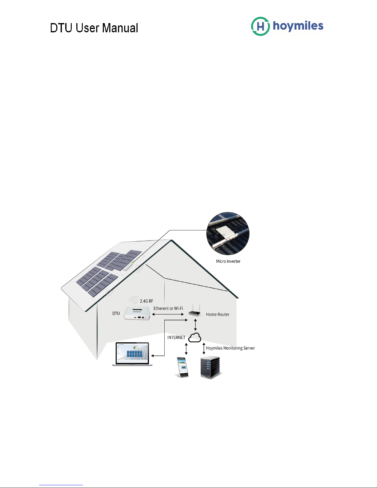
2. The Hoymiles Microinverter System
The DTU is the key component in Hoymiles microinverter system. It works as the gateway,
which is the transfer station of monitoring information in the system. The DTU communicates
with microinverters wirelessly via 2.4G RF, collecting the operating data of the system.
Meanwhile, it sends control commands to microinverters for adjusting the operating state. In
addition, the DTU connects with the Internet to realize the mutual communication of
Hoymiles cloud monitoring platform. The operating data from microinverters and the control
commands from the cloud-monitoring server will be sent through the DTU to the other end.
The remote operation and maintenance are achieved.
The following diagram shows the DTU in the system.

(((((((((((((((((((((((((((((((((((( ( (
6(
Other Elements in the Hoymiles Microinverter System
The Microinverter: Its main function is energy transfer. It converts the DC output of solar
modules into grid-compliant AC power. It also can send the output information of PV panels
and the operation data of the microinverters to the DTU, which is the hardware basis of the
panel-level monitoring. The efficiency of the Hoymiles microinverters is up to 96.7%, and the
MPPT efficiency of the Hoymiles microinverters is up to 99.9%.
The Remote Monitoring Server: It collects the operation data and status of the
microinverters in the system, and provides the panel-level monitoring for the users and
maintenance staffs.
(((((((((((((((((((((((((((((((((((( ( (
7(
3. DTU Basic Operation
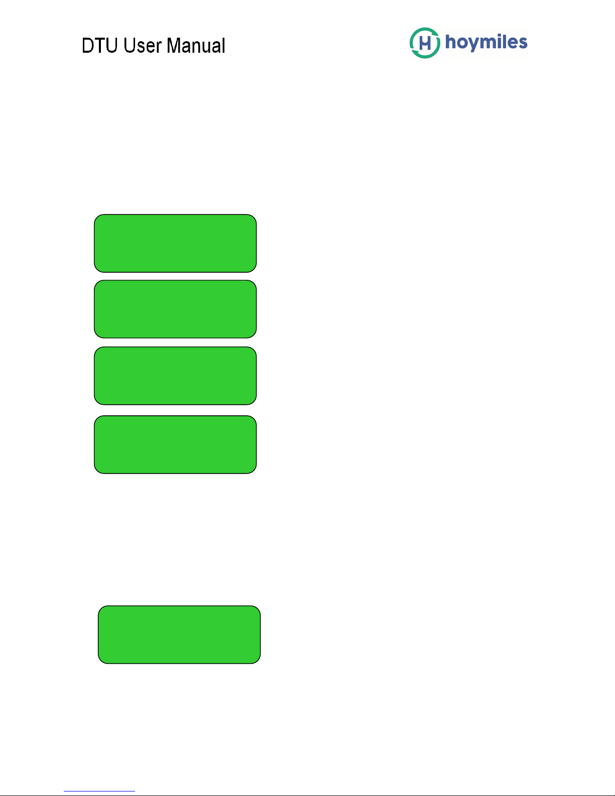
3.1 LCD Screen Display at Start Up
When the DTU starts up, it goes through the initial boot sequence. During this initial boot
sequence, the DTU LCD screen displays start-up progress as shown:
3.2 Normal Operation
When the DTU completes start and obtains the IP address, normal operation begins. During
the normal operation, the LCD screen displays the basic operation status of the system, and
the two screens shown as below alternate all the time.
(
BOOT SYSsetup
10:26:30
System setup…
10:27:55
ETH_BSP_Config
10:27:55
IP: 0.0.0.0
YC 10:27:55 XXXX
IP: 192.168.1.122

(((((((((((((((((((((((((((((((((((( ( (
8(
The data indicates:
(1) Web connection information: “YC”. This means the DTU is connected to the Internet.
If it is “NC”, the DTU is not connected to the Internet.
(2) Time, e.g. 10:27:55.
(3) Local IP address, e.g. 192.168.1. XXX.
(4) Data of the real-time output power in watts, e.g. 0.16kW.
(5) Data of the today’s output energy of the system in kWh, e.g. 0.07kWh.
(6) The total number of microinverters in this system, e.g. ALL: 05.
(7) The number of microinverters normally communicating with DTU, e.g. LINK: 01.
3.3 DTU local Interface
The DTU has the embedded web server. You can use a browser locally to view the
operation data and status of the system, manage the devices and clear fault. You need to
get your computer connected to the same network with DTU to open the DTU local interface
in your browser by entering the IP address shown on the LCD screen.
3.3.1 DTU Home Interface
The home interface shown below will turn up first when you enter the IP address into the
browser. In the home interface, the left side displays the basic information of the system,
including Total Output Power, Total Energy, Today Energy and CO2 Saved; the middle form
displays the operation data of each microinverter, including PV Voltage, Grid Voltage, Grid
Frequency, Grid Power, Today Energy and Internal Temperature. The upward side displays
the total number of microinverters, the number of connected microinverters and the number
of unconnected microinverters.
0.16Kw 0.07kWh
ALL:05 LINK:01
 Loading...