

Page 1
Redimon
v3
Latching monitor unit for Panic Strip
Mode 1 operation - Single push
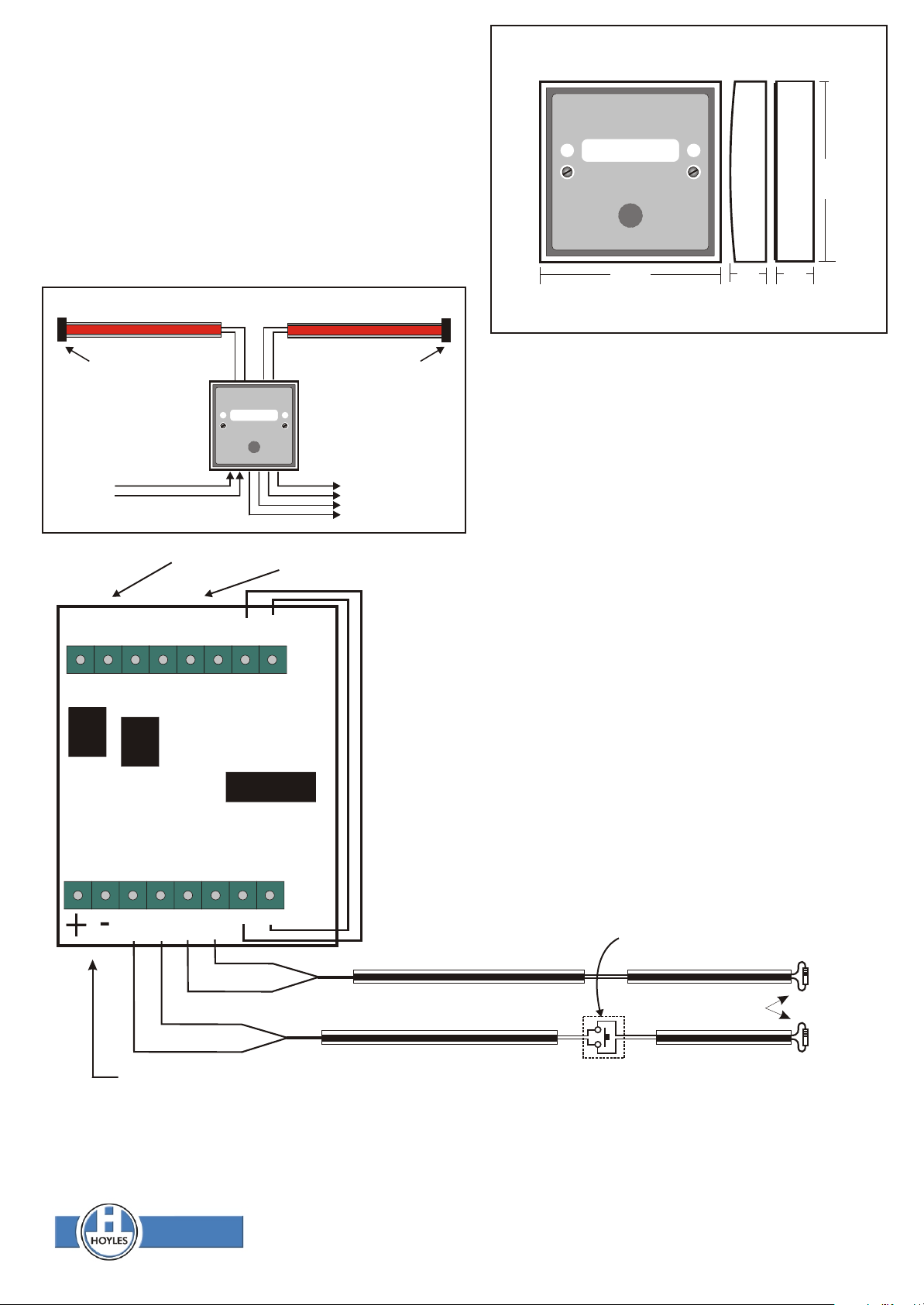
Redimon is a latching monitor unit which fully monitors two
lengths of to give independent alarm and fault
Panic Strip
conditions. An End of Line resistor is fitted at the remote end of
each length of . Pressing the creates a
Panic Strip Panic Strip
short circuit which will be detected as an alarm condition. If the
Panic Strip
becomes disconnected in any way a fault condition
is generated. The Redimon requires 12 volts dc and provides
volt free changeover contacts for both alarm and fault. A Reset
button is provided.
Redimon can also be used to create a double pole EOL circuit for any
momentary action normally open device. E.g. Push button.
Dimensions
v3
Redimon Monitor
Press to Reset
87.0
87.0
18.0 18.0
Panic Strip Type 3 Panic Strip Type 3
E.O.L 6k8
v3
Redimon Monitor
Press to Reset
E.O.L 6k8
12 Volts dc power
45ma max
Alarm output
Fault output
Use these changeover contacts to connect to the personal attack circuit of your intruder alarm.
Use these changeover contacts to connect to the tamper circuit of your alarm
RELAY 1 RELAY 2
NO
COM
ALARM
OUTPUT
COMNC NC
FAULT
OUTPUT
NO
TAMPER
SWITCH
Dimensions in mm
Redimon is supplied with two 6k8 end of line resistors fitted
to the terminals AB and CD for test purposes. If only one
length of is being monitored one of these
Panic Strip
resistors should be left in either AB or CD terminals and the
other terminals used for the .
Panic Strip
Any other type of non-latching open circuit button or switch
could be wired across Panic Strip circuits to complement
the system as in Panic Strip 2 shown below.
These contacts are rated @ 30vdc 1A
NOTE Panic Strip SHOULD NEVER BE
CONNECTED DIRECTLY TO MAINS
VOLTAGE CIRCUITS.
IT IS ONLY RATED FOR SAFE WORKING
ON 43 VOLTS MAXIMUM.
T1 and T2 are normally closed. Opening this circuit will cause a fault
until the circuit is closed again. If wired as shown, removing the unit
cover will cause a fault to be indicated, until the cover is replaced.
T2
T1
A B C D
Panic Strip Type 2
Panic Strip Type 2
11 - 14 volts dc at all times. Quiescent current 30ma Max current 45ma
Under normal circumstances the GREEN LED will be illuminated to show that power is on and the circuits are healthy. When
either is operated the RED LED will illuminate and the alarm relay will change over. If either of the
Panic Strip Panic Strip
circuits becomes disconnected the RED and GREEN LEDs will alternate and the fault relay will operate, this will restore
when the circuit has been repaired. To reset the from an alarm condition press the Reset button.
Panic Strip
Optional open circuit
non-latching push button
Panic Strip Type 3
6K8 Terminating resistors
Panic Strip Type 3
Hoyles Electronic Developments Ltd
T. 01744 886600 F. 01744 886607 E. sales@hoyles.com W. www.hoyles.com
Dwg No: 60136 Oct 2011
Page 2

Redimon
v3
Latching monitor unit for Panic Strip
Mode 2 operation - Double push
In Mode 2 operation a 10K End of Line resistor is fitted at the remote
end of each length of . Pressing either
twice, within a 5 second window will be seen as an alarm condition.
This double action reduces the number of false alarms caused by
accidental pressing. If the becomes disconnected in any
way, or is held pressed for longer than 5 seconds, a fault condition is
generated. The Redimon requires 12 volts dc and provides volt free
changeover contacts for both alarm and fault. A reset button is
provided.
Redimon can also be used to create a double pole EOL circuit for any
momentary action normally open device.
Panic Strip Panic Strip
Panic Strip
eg. Footswitch or
pushbutton.
Dimensions
v3
Redimon Monitor
Press to Reset
R
87.0
87.0
18.0 18.0
Panic Strip Type 3 Panic Strip Type 3
E.O.L 10K
v3
Redimon Monitor
Press to Reset
E.O.L 10K
12 Volts dc power
45ma max
Alarm output
Fault output
Use these changeover contacts to connect to the personal attack circuit of your intruder alarm.
Use these changeover contacts to connect to the tamper circuit of your alarm
RELAY 1 RELAY 2
NO
COM
ALARM
OUTPUT
COMNC NC
FAULT
OUTPUT
NO
TAMPER
SWITCH
TAMPER
OUTPUT
Dimensions in mm
Redimon is supplied with two 6k8 end of line resistors fitted to the
terminals AB and CD for Mode 1 operation and test purposes.
These resistors should be replaced with ones of 10K value for
Mode 2 operation. If only one length of is being
monitored one of these resistors should be left in either AB or CD
terminals and the other terminals used for the .
Any other type of non-latching open circuit button or switch could
be wired across Panic Strip circuits to complement the system
as in Panic Strip 2 shown below.
Panic Strip
Panic Strip
These contacts are rated @ 30vdc 1A
NOTE Panic Strip SHOULD NEVER BE
CONNECTED DIRECTLY TO MAINS
VOLTAGE CIRCUITS.
IT IS ONLY RATED FOR SAFE WORKING
ON 43 VOLTS MAXIMUM.
T1 and T2 are normally closed. Opening this circuit will cause a fault
until the circuit is closed again. If wired as shown, removing the unit
cover will cause a fault to be indicated, until the cover is replaced.
T2
T1
A B C D
Panic Strip Type 2
Panic Strip Type 2
11 - 14 volts dc at all times. Quiescent current 30ma Max current 45ma
Under normal circumstances the GREEN LED will be illuminated to show that power is on and the circuits are healthy. When
either Panic Strip is operated the RED LED will illuminate and the alarm relay will change over. If either of the Panic Strip
circuits becomes disconnected the RED and GREEN LEDs will alternate and the fault relay will operate, this will restore when
the circuit has been repaired. To reset the Panic Strip from an alarm condition press the Reset button.
Optional open circuit
non-latching push button
Panic Strip Type 3
10K Terminating resistors
Panic Strip Type 3
Hoyles Electronic Developments Ltd
T. 01744 886600 F. 01744 886607 E. sales@hoyles.com W. www.hoyles.com
Dwg No: 60136 Oct 2011
 Loading...