

Page 1

MULTIGUARD ANNUNCIATORS MG212XXX & MG216XXX
GENERAL
The MULTIGUARD is general purpose six zone annunciator. The mark resistant decal covers a removable identification panel which
can easily be created by a word processor or graphics package to enable a professional looking facia to be achieved for each
installation. Blanks are supplied with these instructions. The MULTIGUARD is ideal for 24 hour monitoring of many different emergency
alarms. It can be used with EXITGUARD door alarms to enable local and remote warning to be given. It is also suitable for standalone
Personal Attack systems.
There are a number of variations of the MULTIGUARD and these can be identified by the following numbering system
MGXXXXXX
1st 2 characters MG = Multiguard family
1st digit 2 = General Purpose annunciator, 3 = Nurse Call annunciator
2nd digit 1 = Master panel 2 = Repeater panel
3rd digit 1 = 1 pushbuttons (Silence), 2 = 2 pushbuttons (Silence & Reset) 6 = 6 pushbuttons (Zone control)
4th digit 0 = No Power Supply, 1 = Integral Power Supply
5th digit 0 = No Keyswitch 1 = Keyswitch fitted on front panel
6th digit 0 = Red LEDs, 1 = Green LEDs, 2 = Yellow LEDs, 3 = Blue LEDs
Thus stock code MG216110 is a general purpose annunciator master panel with six push buttons, an integral powersupply and battery,
a front panel keyswitch and red indication LEDs
OPERATION.
The basic operation of all units is the same but there are differences in the way that alarm conditions are silenced and reset.
MG212XXX units have a global silence button and global reset buttons. MG216XXX units have individual silence/reset buttons for
each zone. These individual buttons are also used to isolate zones in conjunction with the keyswitch.
When an alarm condition is detected an audible warning is given by the integral sounder, the relevant zone LED flashes rapidly and a
global relay is energised to provide volt free DPCO contacts for signalling to other equipment.
MG212XXX. Pressing F1 silences the alarm condition,restores the global relay to normal and the LED flashes more slowly. When the
cause of the alarm condition has been cleared F2 can be pressed to RESET the visual indication.
MG216XXX. Pressing the relevant Z1 -Z6 button silences the alarm condition, restores the global relay to normal and the LED flashes
more slowly. When the cause of the alarm condition has been cleared the relevant Z1 - Z6 button can be pressed again to RESET the
visual indication.
If a subsequent alarm condition occurs before earlier ones have been reset then all prior indications are temporarily suppressed in
order to emphasize the latest event. After silencing all indications are displayed again as slow flashing LEDs.
If a keyswitch is fitted and connected to F3 (see below) zones can be omitted or isolated. Pre-selected the zones for ommission by
turning the keyswitch and pressing the relevant Z button. To complete the ommission procedure return the key to its anti-clockwise
position. The zone LEDs will glow steady if ommitted.
The basic mode of operation can be changed to suit other application. See function changes below for details.
INPUTS
MULTIGUARD annunciators are all fitted with 16 inputs. Each input has a highimpedance and will cope with high cable resistance. The
inputs are capable of monitoring normally closed and normally open circuits and d.c. voltages between 2 and 30 vdc.
The 16 inputs are allocated as follows:
I1 - I6 Alarm inputs. N.C. open to alarm ie remove +ve, but see F4 below
Z1 - Z6 Zone Resets (MG212XXX). Silence, Reset and Isolate (MG216XXX) Momentary +ve applied to reset or silence etc.
F1 - F 4 function inputs. +ve applied to operate function
MG212XX Inputs F1 and F2 are connected to function buttons on the front panel. F1 is a SILENCE button F2 being RESET.
MG216XXX Inputs Z1 - Z6 are connected to six buttons marked Z1 - Z6 on the front panel. Thus it is possible to silence and reset the
system from a remote point if necessary.
OUTPUTS
There is a DPCO (1A 30Vdc) global relay output which follows the sounder. Whenever the sounder operates the relay is energised. A
serial output is also provided to transmit data to a remote repeater(s), driver(s) or relay card(s).
FUNCTION CHANGES
The function terminals can be linked to +ve either permanently or through switches to acheive differnt results:
Link F1 to +ve. to acheive silent operation. (MG212XXX & MG216XXX)
MG212XXX
Link F2 to +ve. If an alarm condition is detected the MULTIGUARD will sound and the relevant zone LED will flash rapidly. This visual
and audible indication will continue until the cause of the alarm condition has been cleared.
Link both F1 & F2 to +ve. If an alarm condition is detected the MULTIGUARD remains silent and the relevant zone LED will flash slowly
until the cause of the alarm condition is cleared.
F3 is a global isolate facility. By holding this terminal at +ve the system will be isolated. Any alarm conditions which existed at the time of
isolation will remain in memory and will re-indicate when the system is restored to normal monitoring.
F4. By linking F4 to +ve the alarm inputs I1 - I6 become N.O. instead of N.C.
MG216XXX
Link F2 to +ve. If an alarm condition is detected the MULTIGUARD will sound and the relevant zone LED will flash rapidly and the relay
will operate. Pressing Zn will Silence the buzzer and de-energise the relay. If the alarm input is restored the LED will extinguish, if the
alarm input is still present the LED will continue to flash but slowly until the input is restored.
Link both F1 & F2 to +ve. If an alarm condition is detected the MULTIGUARD remains silent and the relevant zone LED will flash slowly
and the relay will not operate. When the cause of the alarm condition is cleared the zone fully resets automatically.
F3 is usually connected to a panel mounted keyswitch (standard on MG216X1X) to enable buttons Z1 - Z6 as isolate buttons.
By linking F4 to +ve the alarm inputs I1 - I6 become N.O. instead of N.C.
Dwg No:60031:0 Iss 3
Page 2
IT IS IMPORTANT THAT THE MULTIGUARD IS FIXED TO A FLAT SURFACE. IF THE BOX DISTORTS IT WILL
BE DIFFICULT TO CLIP THE VARIOUS COMPONENTS TOGETHER TO FORM A SECURE HOUSING.
Connection & Power Up sequence.
The MULTIGUARD has a short test or verification sequence on power up. You should verify that the unit as supplied is functioning normally
before making any connections.
1. Plug in the battery. The plug is polarised to maintain the correct polarity. Ensure F4 is linked to +ve. The integral sounder will beep at 1 second
intervals.
MG212XXX
2a. Press the SILENCE button F1. The LED's will flash twice and then remain steady. Press the RESET button F2. The unit is now ready to
accept connections.
MG216XXX
2b. Press any button Z1 -Z6. The LED's will flash six times and then extinguish. The unit is now ready to accept connections.
3. Connect the 220/240vac mains to the Live, Neutral & Earth terminals. Ensure the mains fuse is fitted and the transformer leads (Blue &
Yellow) and earth lead (Green) are connected to the PCB.
4. Clip the PCB assembly onto the back box.
5. Switch on the power. Observe the green Mains On LED.
6. Dress the cable into the cable channel, trim to length and terminate as appropriate. Remove link F4 if monitoring closed circuits.
7. The system can now be tested and the decal and lid clipped into place.
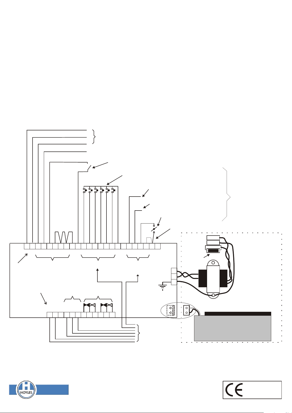
+
To EXITGUARD
M
Voltage monitoring with respect to -ve (1.5 - 30Vdc)
Closed or open circuit contacts
Remote zone control. Apply momentary +ve to Z1 - Z6
Link un-used
inputs to +ve
if configured
for N.C. I/Ps
- + 1 2 3 4 5 6 + + 1 2 3 4 5 6 + + 1 2 3 4 + -
INPUTS
All terminals marked +ve & -ve form a
common power supply feed. They can
be used for dc in or out. However, Do
not apply 12 volts dc to these terminals
on mains powered (ie. MG2121XX or
MG2161XX) versions
SERIAL
OUTPUT
ZONE RESETS FUNCTION
INPUTS
RELAY
OUTPUT
- + X S D C
F1 Auto or reomte SILENCE. Apply +ve
F2 Auto or remote RESET. Apply +ve
F3 ISOLATE functions. Apply +ve
Link F4 to +ve to change I1 - I6 from N.C. to N.O.
240/220
vac
50Hz
Mains Fuse
16 v.a.c
INPUT
N
E
L
Apply +ve to
activate function
These components are
only fitted in the
MG2121XX and
MG2161XX versions.
The MG2120XX and
MG2160XX versions
should be powered from
an external power
supply connected to
any unused +ve & -ve
terminals.
The standby battery is connected
via a polarised socket on the
reverse of the p.c.b.
Multicore cable
to repeaters, relay
or interface cards
See MG226000
instructions
12 volt 0.8 Ahr standby battery
POWER SUPPLY
The integral 13.8vdc power supply (if fitted) is rated at 250ma., and is supplied with a rechargeable 0.7 Ahr standby battery. The
MULTIGUARD circuitry has a maximum power requirement of 60ma . The integral power supply will therefore support its own six zone
electronics plus a further three units or repeaters and/or relay cards.
Hoyles Electronic Developments Ltd
T. 01744 886600 F. 01744 886607 E. sales@hoyles.com W. www.hoyles.com
Dwg No:60031:0 Iss 3 Apr 2001
MG212000
MG212100
Complies with Council
Directive 89/336/EEC
 Loading...