

Page 1
S351 Universal Timer Relay
Control Functions
Commutating Relay
Setup
The function control terminals C and D
are not connected. The Relay control
jumper is in position R0 and the timing
range T1 and T2 are not connected
and have no function. The POT has no
function.
Operation
Apply a trigger. The relay changes over
and the green led indicates. This will
remain until the first trigger is removed
and a second trigger is applied, then
the relay will switch back and the red
led will indicate, until the trigger is
removed when the led will extinguish.
A-stabling Relay
Setup
The function control terminals C and D
are both connected to +ve. The Relay
control jumper is in position R0 and
has no function.
Rate of A-stable.
Without a link in T1 and T2 is the lower
range from less than 1 second up to 10
seconds. When T1 and T2 are linked,
this is the upper range from 3 to 60
seconds.
Operation
Apply a trigger and the relay will astable. When the relay is switched the
green led illuminates and when the
relay is un-switched, the red led
illuminates. When the trigger is
removed, the relay will stop a-stabling,
reset to the un-switched state and the
led will extinguish.
Timing Function with Timing Function with
latching trigger momentary trigger
Bell cut off timer Reset pulse
Setup Setup
The function control terminals, D is The function control terminals, C is
connected to +ve and C is not connected to +ve and D is not
connected. The relay control jumper is connected. The relay control jumper is
in position R1. in position R1.
Timing ranges Timing ranges
Without a link in T1 and T2 is the lower Without a link in T1 and T2 is the lower
range from less than 1 second up to 60 range from less than 1 second up to 60
seconds. When T1 and T2 are linked, seconds. When T1 and T2 are linked,
this is the upper range from less than 1 this is the upper range from less than 1
minute up to 60 minutes. minute up to 60 minutes.
Operation Operation
Apply a trigger, the green led Apply a trigger, the green led
illuminates, but the relay doesn’t illuminates, but the relay doesn’t
switch. If the trigger is removed, the led switch. If the trigger is removed, the
extinguishes and the timing is stopped. timing continues. When the time
If the time period expires while the period expires with the trigger
trigger is still applied, then the relay removed, then the relay switches and
switches and the red led illuminates. the red led illuminates. This will remain
This will remain until the trigger is for 1 second, then the relay will switch
removed. back and the led extinguish.
Max time switch Pulse stretching
Setup Setup
The function control terminals, D is The function control terminals, C is
connected to +ve and C is not connected to +ve and D is not
connected. The relay control jumper is connected. The relay control jumper is
in position R0. in position R0.
Timing ranges as above. Timing ranges as above.
Operation Operation
Apply a trigger, the green led Apply a trigger, the green led
illuminates, and the relay switches. If illuminates, and the relay switches. If
the trigg er is remo ved, the l ed the trigger is removed, the timing
extinguishes, the relay switches back continues. When the time period
and the timing is stopped. If the time expires with the trigger removed, the
period expires while the trigger is still relay switches back and the red led
applied, then the relay switches back illuminates for 1 second and then
and the red led illuminates. This will extinguishes.
remain until the trigger is removed.
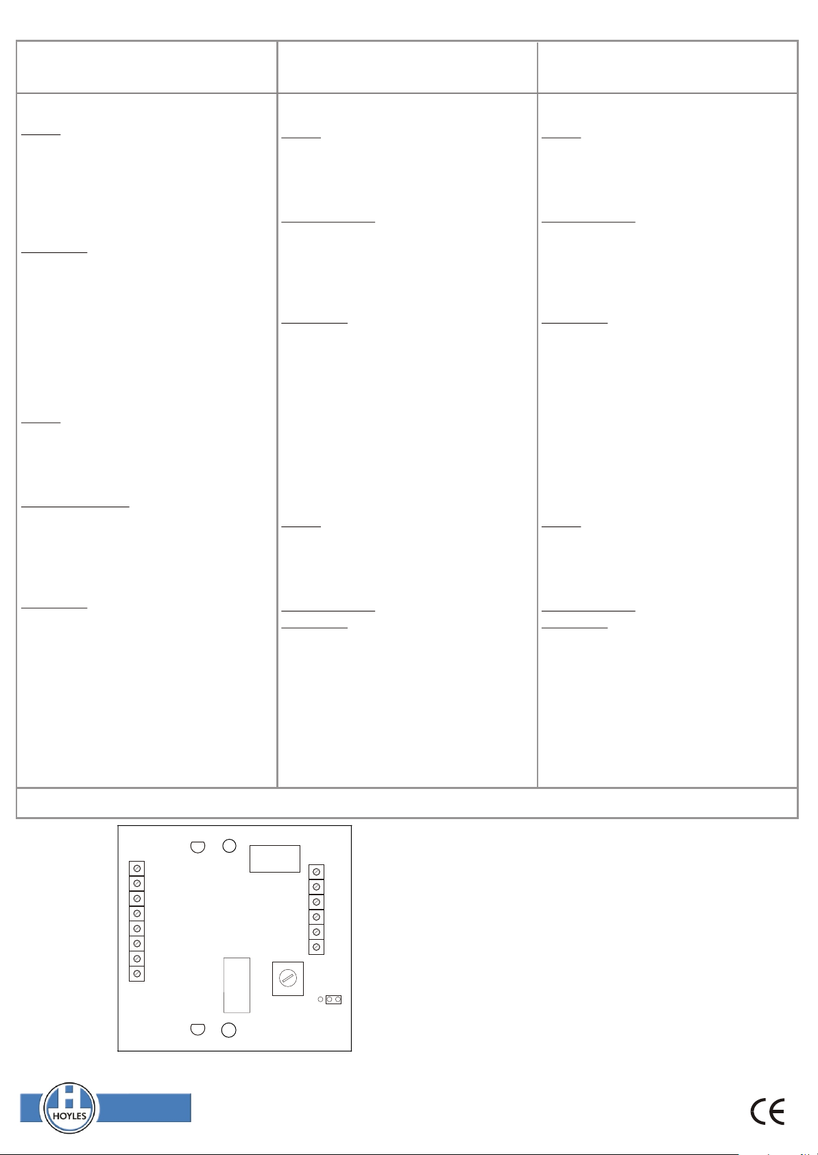
The trigger terminals, A is a -ve applied to trigger, B is +ve applied to trigger.
12V DC
-VE TRIGGER
+VE TRIGGER
Function
Controls
Timing
Range
Note
+
-
A
B
C
D
T1
T2
LED1
LED2
021-105 iss2
NC
RELAY1
COM COM
NCNO NO
RELAY2
MIN MAX
J1
Relay
R0
R1
Control
This unit requires 12v dc to power it at all times. (10-14v dc).
If the input is not removed when the timing has finished in both
momentary trigger modes, then the led will remain illuminated red
and the relay will remain in the state that it was when the led
illuminated red until the trigger is removed.
Contact ratings
The relay is DPCO rated 1Amp @ 12v dc. It must not be used to
switch mains voltages.
Boxed Version. If you have the boxed version of the S351, the decal
(included) has a clear window 10mm x 46mm. The area under the
decal is 12mm wide to take standard labelling machine tape. The
window is free from adhesive, nevertheless, it is wise to maintain
cleanliness and avoid fingerprints on the inside of the window. If a
labelling machine is not available a paper label can be used. For a
small extra charge these products can be factory labelled to your
requirements (subject to a character limit).
Hoyles Electronic Developments Ltd
T. 01744 886600 F. 01744 886607 E. sales@hoyles.com W. www.hoyles.com
60135 Iss 1 Sept 11
 Loading...