

Page 1

MAYDAY LMW2 Lone Worker Safety System
Specification. IN3 Input from a movement detector such as a PIR (Normally Closed
The MAYDAY is a loneworker safety system. It is designed to give
audible and visual warning to prompt staff to take action by cancelling
a warning after a pre-determined period. Failure to take action will
result in a secondary alarm operating after a further pre-determined
period. This is used to raise an alarm to call for assistance which can
be either a simple sounder and visual indicator or a voice message
transmitted via a speech dialler (not supplied) via a landline. The two
time periods are separately adjustable. 20 - 60 minutes and 2 - 10
minutes respectively. The MAYDAY is mains powered and supplied
with a rechargeable 12v 0.8Ahr standby battery. The integral 12v
power supply will deliver 150ma for ancillary items.
The unit is
housed in a plastic enclosure approx. 125w x 175h x 55d ( mm).
The MAYDAY has the following integral indications and controls:-
1. An On Off keyswitch to arm the unit.
2. An OK button to restart the countdown timer and reset the alarm.
3. A green Power On LED.
4. Four red System Active countdown LEDs.
5 . An integral piezo sounder. (85db at 10cm)
6. Two adjustable countdown timer controls. These are fitted
internally and only used during the installation set-up.
Five inputs are provided for connecting ancillary devices:IN1 Remote OK buttons to supplement the front panel OK button.
(Normally Open -close to acknowledge OK)
IN2 To arm the MAYDAY from a keyswitch or other device. (Normally
Closed - open to start lone working)
-open on detection - ie OK)
IN4 Input from a speech dialler. (Apply a -ve for OK)
IN5 Timer set-up. This is a divide by 60 facility (eg 57mins= 57sec).
Volt free contacts are provided by three independent relays:-
Relay 1 operates when the keyswitch is thrown to arm the unit.
Relay 2 operates at the end of the first pre-determined run down
delay T1 (20-60 minutes).
Relay 3 (normally on, off when operated) operates at the end of
the second pre-determined countdown delay T2 (2-10 minutes).
Eight outputs are provided for remote indications:
LED1 - 4 follow the LEDs on the front panel.
LED5 Remote buzzer, follows internal buzzer
LED6 Remote LED, all indications.
LED7 Remote LED to indicate T2 has run out.
LED8 Remote power LED.
Timer set-up procedure.
With IN2 closed (or keyswitch OFF), link out IN5, LED’s 2 and 4 only
illuminate. Set T1 and T2 pots approx. (Best guess). Press the OK
button, the unit bleeps and leds 1 and 3 only illuminates for T1 time in
seconds. At the end of T1 the unit bleeps and leds 1 and 2 only
illuminate for T2 time in seconds. At the end of T2 the unit bleeps and
reverts to leds 2 and 4 only. Adjust the pots accordingly and repeat
until time T1 and T2 minutes are correct as indicated in seconds.
Remove the link IN5 and the unit is set to operate in minutes.
Loneworker Scenarios where MAYDAY could be used
The notes below will assist in deciding how MAYDAY and ancillary equipment should be used and configured for any particular situation.
The first consideration should be; where are the responders located?
Scenario 1
AV AVAV AV
In this scenario a worker is only allowed in an area for a restricted work that the worker should have vacated the area and should be rescued.
period, perhaps 30minutes. This could be a freezer where reduced
temperature for long periods may be harmful to health or an area with a
high concentration of fumes or very high temperatures.
The worker would arm the MAYDAY with the key to start the countdown front panel of the MAYDAY should be disabled (see below).
timer before entering the area. During the countdown period pre-alarms
are generated to gradually warn that time is running out. At the end of the
restricted period a full alarm is given to alert responders outside the area
T1
T2
MIN
L1
+
L2
L3
+
L4
S
D
C
MAX
A MAYDAY and possibly an AV indicator within earshot of the responder are all
that is needed, no other ancillary devices are needed though repeat AV
indicator(s) may be of benefit to the worker. In this scenario the OK button on the
1 x LMW2
1 or more S1778PR AV units located near the responder (Optional)
1 or more S1778PR AV units for the worker (Optional)
BATTERY FUSE
TPR
TPR
L8
+
L7
L6
+
L5
To re-chargeable battery
in back box
Sited in work area to give
visual indication of System
IN USE and audible
indication to vacate the
area.
Optional
S1778PR
Buzzer & Lamp Unit
Sited near the responder to
give visual indication of
System IN USE and audible
indication of assistance
required.
BZ
+
L1
L2
Optional
S1778PR
Buzzer & Lamp Unit
BZ
+
L1
L2
NC COM NO NC COM NO NC COM NO
16 V
RELAY 1 RELAY 2 RELAY 3
AC
To transformer in back box
MM
+ + + + +
IN1
IN2 IN3 IN4 IN5
IN1 is linked to
disable the OK button
++
--
CONNECTOR
BATTERY
DWG No 60108 iss 4 Jun 12
Hoyles Electronic Developments Ltd
T. 01744 886600 F. 01744 886607 E. sales@hoyles.com W. www.hoyles.com
Page 2
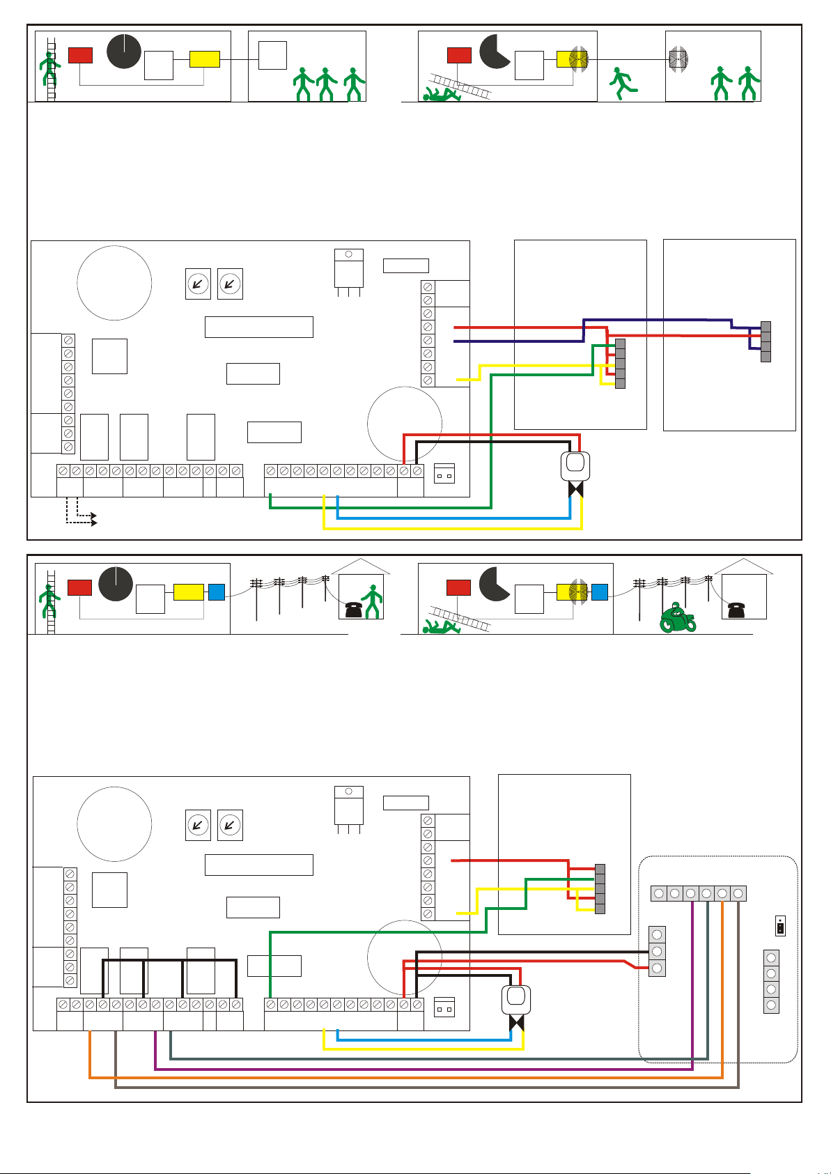
Scenario 2
PIR PIR
AV
OK
The working practice in force here allows lone working for long periods of is needed, no other ancillary devices are needed though a repeat AV indicator(s)
time. It could be a full 8 hour shift but on a remote part of a site. The with OK acknowledge buttons may be of benefit for the worker depending on the
responder(s) could be some distance away but on the same site. size of the working area. An alternative to an OK button would be one or more
The worker would arm the MAYDAY to start the countdown timer. Prealarms are generated in the same way as in 1 above. Periodically the 1 x LMW2
worker presses an OK button to restart the countdown timer. If the worker
does not, then eventually the MAYDAY generates a full alarm at a remote
audible/visual indicator AV to alert the responder.
A MAYDAY and an AV indicator within earshot of the responder are all that
AV
AV
OK
Passive Infra Red detectors, this could allow for hands free operation.
1 or more S1778PR used as AV units located near the responder
1 or more S1703PR or S1708PR used as AV/OK buttons (Optional) and/or
PIRs (Optional) for the worker.
MIN
T1
T2
MAX
BATTERY FUSE
TPR
TPR
Sited in work area to give
audible & visual indication
and act as an OK
acknowledge button.
Sited in responder area to
give audible & visual
indication that assistance
is needed.
L8
BZ
+
L1
L2
L1
L2
L3
L4
+
+
L6
+
L5
L7
+
Optional S1703PR or
S1708PR AV Unit with
S
OK Button
P1
P2
BZ
+
L1
Optional S1778PR
AV Unit
D
C
NC COM NO NC COM NO NC COM NO
16 V
RELAY 1 RELAY 2 RELAY 3
AC
MM
+ + + + +
IN1
IN2 IN3 IN4 IN5
++
--
CONNECTOR
BATTERY
One or more optional PIR
movement detectors in
PIR
the work area.
Battery connection are not shown for
To transformer in back box
clarity
Scenario 3
PIR PIR
The working practice here and operation is the same as 2 above but the A MAYDAY and an auto-dialler are needed, no other ancillary devices are
responder(s) is remote from the site. needed though one or more OK/ AV buttons may be of benefit to the worker. An
The communication to the responder uses an auto-dialler via a landline.
Signalling can also be given for the start and end of lone working. Up to
three responders telephone numbers can be programmed into the dialler. 1 x LMW2
Each is dialled in turn until acknowledge by the responder dialling 8. A
fourth number can be programmed for the lone worker. If no responder
acknowledges then the lone worker is automatically called to advise that
he/she will be working alone without cover. A separate landline or mobile is
required for this return call.
L1
+
L2
L3
+
L4
S
D
C
NC COM NO NC COM NO NC COM NO
16 V
RELAY 1 RELAY 2 RELAY 3
AC
AV
OK
MIN
T1
MM
T2
MAX
+ + + + +
IN1
IN2 IN3 IN4 IN5
AV
OK
alternative to OK buttons would be one or more Passive Infra Red detectors, this
could allow for hands free operation.
1 x SD1E Autodialer to contact the responder
1 or more S1703PR or S1708PR used as AV/OK buttons and/or PIRs for the
worker.
1 x Mobile phone for the worker (Optional)
BATTERY FUSE
--
++
TPR
TPR
L8
+
L7
L6
+
L5
BATTERY
CONNECTOR
Optional S1703PR or (08)
AV Unit with OK Button
Sited in work area to give
audible & visual indication
and act as an OK
acknowledge button.
P1
P2
BZ
+
L1
One or more
optional PIR
PIR
detectors
in the work area.
Transformer & battery
connections are not
for clarity
D
Tamp Abort
C B A
O/P1-ve
0v
+12vdc
+
Trig
-
Polarity
B1
A1
B
A
Landline
A= White
B= Orange
Page 3

Scenario 4
If an auto-dialler SD1E is used for communication as in scenario 3 then it is phone. This tells the autodialer to send a signal to the MAYDAY to restart the
possible to use the communication link to enable the worker to use a countdown timer. If no signal is received then auto-dialler calls the responder to
mobile phone to generate an OK signal to restart the countdown timer. This alert him to a problem on site.
would enable say a patrolling security guard to cover a large site without
the need for dozens of hardwired OK/AV acknowledge buttons. Optional
OK/AV buttons can be used if necessary to enable the countdown timer to
be reset.
Towards the end of the countdown period the MAYDAY generates a signal
to cause the auto-dialler to call the worker’s (guard’s) mobile phone. The
worker answers and responds by pressing a predetermined key on his
GSM
Network
Such a system requires:1 x LMW2
1 x SD1E auto-dialler
1 x Mobile phone
1 or more OK/AV buttons (Optional)
BATTERY FUSE
L1
+
L2
L3
+
L4
S
D
C
NC COM NO NC COM NO NC COM NO
16 V
RELAY 1 RELAY 2 RELAY 3
AC
MIN
T1
MM
T2
MAX
+ + + + +
IN1
IN2 IN3 IN4 IN5
Operation.
1. The green mains on LED is illuminated at all times unless the
mains has failed.
2. When the keyswitch is thrown to activate ie arm the MAYDAY the
four red System Active countdown LEDs adjacent to the OK button
illuminate and the countdown timer T1 starts. If the keyswitch is
used to switch off at any time then no further timing or other action
takes place. (This would be the case for scenario 1 above)
3. When armed the Lone Worker is expected to periodically press
the OK button on the MAYDAY or an ancillary OK/AV button within
the workplace. Alternatively if a movement detector is used to
sense movement within the workplace then no action other than
movement is required by the worker.
4. If the OK button or a remote OK button is pressed, the panel
buzzer will bleep to acknowledge this. If a PIR movement detector
senses movement with the workplace then the countdown timer is
reset without any bleep. This minimises annoyance when moving
around constantly.
5. As the countdown timer runs down the four LEDs gradually
extinguish to give a visual indication of time remaining. As each
LED extinguishes a bleep is heard.
6.At the end of the first countdown period only one LED remains
TPR
TPR
L8
++
--
CONNECTOR
+
L7
L6
+
L5
BATTERY
Transformer and battery
connections are not
shown for clarity
SD1E
Auto-dialler
Tamp Abort
O/P1-ve
0v
+12vdc
D
C B A
illuminated and the bleeps become more frequent during the
second countdown period to warn the lone worker that action must
be taken to reset the countdown timer by pressing an OK button or
in the case of scenario 4 he/she will be called by mobile phone to
dial 8 as an OK
7. If no action is taken before the end of this second countdown then
a full alarm condition is raised. This may be an AV device on the
same site to call the responders (Scenario 2) or a message from a
speech dialler to call a remote responder. (Scenario 3 or 4)
8.Under mains fail condition the green power on LED will
extinguish.
9. If the mains have failed prior to arming then, on arming, the green
power LED will flash for a short period and then extinguish. The
MAYDAY will continue to function but the four red countdown LEDs
will flash.
10. If the mains fails after arming then the MAYDAY will behave as
though the primary countdown timer has run down and only a short
period remains before an OK button should be pressed. The
MAYDAY assumes that there is a possibility that the cause of the
mains failure could be the lone worker.
The above conditions assume that the rechargeable standby
battery is healthy.
+
Trig
-
Polarity
B1
A1
B
A
Landline
A= White
B= Orange
Hoyles Electronic Developments Ltd
T. 01744 886600 F. 01744 886607 E. sales@hoyles.com W. www.hoyles.com
Page 4

Speech dialler setup for MAYDAY lone worker alarm
The notes below are our recommended set up for use with a MAYDAY lone
worker alarm when connected in accordance with our installation
instructions. If you wish to set the SD1E differently then you should
consult the installation and operation manuals supplied.
The SD1E is a 4 channel 4 number speech auto-dialler. (The SD1E operators
manual refers to channels as trigger inputs). The channel inputs are A,B,C and
D. Channel D is factory set as an abort channel and needs to be reprogrammed as a message channel (see 7 below). Each channel can give a
different message. In the notes below a message is composed of two phrases,
a commom phrase and a channel specific phrase. The common phrase is
referred to as phrase O and the channel phrases as A,B,C and D. Refer to the
table below for an example of recommended phrases. Write your own phrases
in a similar table before you start recording. You have a total of 40 seconds to
record all 5 phrases. It is recommended that all messages be recorded in order
in one session, to avoids trying to fit a spoken message into a predefined time
slot.
Throughout these instructions the keypad presses are denoted in bold capitals
eg ENT. The LCD display readings are denoted in bold italics eg READY
1.If this is a first time install short circuit the Factory Restart pins JP2 whilst
applying 12vdc power. This erases the memory of all phrases, numbers and
other set up parameters. The unit should bleep and display PLEASE
RECORD. Complete all programming before connecting the BT line.
2.Next enter the PASSCODE '1234'. The display should read READY.
3.You must now record at least one message.
3.1.Press ENT. The display will alternate between: ENT 1-4 : OR O-D. Press 0
and the display will read RECORD PHRASE 0. (The 1-4 is for the telephone
numbers see later). Phrase 0 is the common phrase and will be announced first
in each message.
3.2.To record the phrase press ENT and the display shows REC-40, and starts
to count down. Speak your phrase into the integral microphone of the SD1E.
When you have recorded the phrase, press ESC. This will stop the timer and
the display will again alternate between ENT 1-4 : OR O-D. waiting for you to
record the next phrase.
3.3.Record the phrases one at a time, To record the A phrases, press A, the
display will read RECORD PHRASE A. Press ENT and the display will show
REC and the remaining time. Press ESC at the end of phrase A. While
recording, the total time remaining will be displayed.
3.4. Record phrase B by pressing B and repeating the procedure 3.3 above.
3.5.Press ESC to get back to READY display.
4.Next programme the telephone numbers.
4.1.From the READY display, press ENT the display will alternate between:
ENT 1-4 : OR O-D, press 1 to programme the first telephone number to be
dialled followed by the telephone number, including any access codes for
PABX system, and press ENT. The display will revert to alternating between:
ENT 1-4 : OR O-D. Press 2 to programme the second telephone number to be
dialled followed by it's number. Repeat the process for number 3. Number 4 is
usually made available for the lone worker’s phone from which he/she can
acknowledge and reset the MAYDAY. If you get a digit wrong, press the, A
button to correct.
4.3.Press ESC to get back to READY display.
5.Next set up the SD1+ output to acknowledge the Mayday.
5.1.From the READY display press 6. The display should read OUTPUT. Press
ENT the display should read ACTIVE. Press B until the display reads
SUCCESS and then press ENT the display should read READY.
This must be used if the Mayday calls the lone worker's mobile phone to be
acknowledged and reset the MAYDAY timers.
6.Next set up the call routing. Which numbers to call for a particular channel.
6.1.From the READY display press 7 the display should read ROUTE- Press ENT.
The display should read A>1234. Press the numbers 1,2,3 or 4 to toggle the
display numbers on or off as required. In a typical setup telephone numbers 1, 2
and 3 may be toggled off for channel D, thus the display would read D>4. This is
the only number that will be called when channel D is triggered. The message
sent will be the common phrase O plus phrase D
6.2.When you are satisfied that the numbers are correct for channel A the
remaining channels B>1234, C>1234 and D>1234, can be scrolled through by
pressing button B. They are set up by toggling as in 6.1 above. When all are set
press ENT and the display should read READY.
6.3.We recommend that channels A,B and C call each of the four numbers 1,2, 3
and 4. Channel D should be reserved for calling the lone worker's phone when the
unit requires to be acknowledged. Thus the routing for channel D should read D>
4
7. Next set up the ABORT input channel as channel D.This allows the abort input
terminal to be used as channel D and also the dialler to be reset by the passcode if
no one is available to acknowledge its dialled numbers.
7.1.From READY, press 8, the display should read ABORT-, press ENT and
press B repeatedly until the display reads PASSCODE. Press ENT and the
display should read READY.
8.Next set up the acknowledgement to stop the dialler from repeatedly dialling.
8.1.From READY press 0 and the display should read CLRBY- press ENT and
then the display should show how many acknowledgements are required to stop
the dialler re-dialling. Press the B button repeatedly until you see the number that
you require, (we recommend 'ANY-1' ) and then press ENT. The display should go
back to READY.
If you select the NO-ONE option the SD1E will continue to call if numbers are
engaged or not answered but will stop when one is answered even if by an
answering machine. The NO-ONE is therefore not recommended.
While it is possible to dial to a pager, it is not recommended, as the pager
has no acknowledge or return call facility. The acknowledge facility, requires
the called person to press 8 to acknowledge. For this reason your message
should include the words "press 8 to acknowledge".
9.To erase the messages and start again.
9.1.From READY, press ENT, the display will alternate between: ENT 1-4 : OR O-
D. Press ENT again, the display should read ERASE-. Press B the display should
read SPEECH press ENT and the display should revert to ENT 1-4 : OR O-D..
Press ESC to return to READY. All phrases now need to be re-recorded, see 3
above.
10.To erase telephone numbers. (assuming you are in programme mode)
10.1.From READY press ENT. The display will alternate between: ENT 1-4 : OR
O-D. Press ENT again and the display will show ERASE- press B twice to scroll
the display to show PHONES. Press ENT to accept and the display should revert
to READY. You will now need to re-programmed the numbers as in 4 above.
Pressing ESC from display READY should display SD1+. To get back to the
READY display, enter the passcode 1234. To return to the SD1+ wait for 60
seconds or repeatedly press ESC. Other options such as changing the passcode
or setting up the BT line as pulse or tone should be done from the SD1+ operating
manual.
Phrase O XYZ Ltd. Newtown
Phrase A Lone working has started. Please press 8 to acknowledge you are on call.
Phrase B Lone working has stopped. Please press 8 to acknowledge.
Phrase C Lone worker in difficulty. Please press 8 to ackowledge you will attend.
Phrase D Only press 8 if you are not in difficulty and you are the correct recipient of this message.
Message to Name Telephone Number
st
1 Aider No. 1
st
1 Aider No. 2
st
1 Aider No. 3
Wandering Lone Worker only
 Loading...