

Hoyles GEMINI Battery powered fire alarm User Manual
GX32 Battery Powered Fire Alarm System
Installation Testing the system
It is assumed that installers are familiar with installing cables and fixing the Turn the keyswitch to TEST MODE. The sounder will give a low pitch bleep
various components etc.. The system is battery powered and presents no every 5 secs. Insert the black test key in the underside of the call point to
electrical risk to either installers or users. Callpoint/Sounder units are displace the glass. Only the control sounder will sound. Remove the test key.
generally fitted at a height of 1.2m AFL. Remove the front cover and glass While still in TEST MODE visit each call point in turn. Inserting the black test
and separate the back box. Pre-drill the back boxes if necessary to take the key sounds only the sounder of the call point being tested. When all call
interconnection cable. Fit the back boxes to the wall and introduce the points have been tested switch the control to the RESTART position.
cable. Strip the sheathing and cores as necessary.
Start connecting at the remote End of Line unit and work back towards the
control panel. Connect the Amber and Blue of the cable to PA and PB
respectively. Fit a link in the terminals marked EOL. Connect the battery.
The unit should bleep. This will be repeated every 10 secs.. Re-assemble
the unit onto the back box. Refit the glass - the sounder will give a double
whoop within 10 secs. to confirm correct installation. Refit and secure the
front cover. If on fitting the glass and cover a long tone followed by double
bleeps every 5 secs. this indicates that there is a problem on the previous
section. This could be: a short or open circuit on the cable, a reverse
connection, no battery in the previous unit or no EOL link fitted.
At the next unit connect the Amber and Blue of the cable from the End of
Line unit to EA and EB respectively of this unit. Connect the Amber and
Blue of the cable leading towards the control panel to PA and PB
respectively. Reassemble the unit as above and check for the double
whoop on this unit.
Repeat the above procedure at each unit. Do NOT start to connect the next
call point until you have heard the double whoop confirmation. At the
control panel connect Amber and Blue to EA and EB respectively. Ensure
that the keyswitch is in the RESTART position. Connect the batteries
(observe the correct polarity). The green system healthy LED should start
to flash within 10 - 15 secs.. Fit the control panel front onto its back box. If
the green LED does not flash check the batteries and cable connections in
the control and the first call point.
Fault Finding
Fault indication is given audibly and visually at the control and
can be caused
by exhausted or partially exhausted batteries, cable connections or cable
damage. If fault indication occurs on installation or on extending the system it
could be that the end of line link is not fitted or two have been fitted.
Switch to TEST MODE, any call point with a partially exhausted battery will
give a single high pitched bleep at 5 sec. intervals. Remove the callpoint and
replace the battery while in TEST MODE. All Callpoint and Control panel
batteries should be changed.
A double high pitched bleep every 5 secs. indicates that there is a cable fault
between the bleeping unit and the next unit towards the end of line. This
could also indicate a totally exhausted battery in the next unit.
Any battery replacements or cabling alterations should be done with the
keyswitch in TEST MODE otherwise it will be necessary to follow the
installation procedure above.
If only part of the system is sounding as a fire condition and it is not possible to
silence it from the control this would indicate that a cable has been damaged
and it is not possible for the silence signal to be received. In this case it will be
necessary to remove the batteries from the sounding call points and follow
the installation procedure above.
NOTE: The GX32CIE is not able to silence smoke alarms that are still
sensing smoke. If it is not possible to silence the call points beyond this
detector this would indicate that some of the batteries are approaching the
battery fail point. It will be necessary to clear the smoke first.
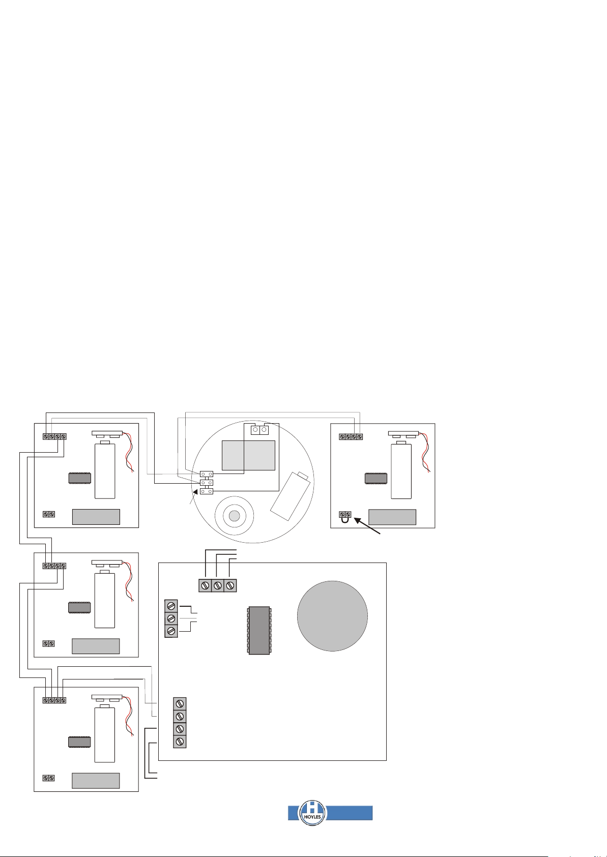
Blue
Amber
EA EB PA PB
PP3 PP3
Blue
Amber
Blue
GX32MCP GX32MCP
EOL
Amber
GX32S/1
Black
Red
- +
ery
t
at
3 B
P
P
GX32SMi
E.O.L link must be fitted
to last call point on system
Amber
Blue
EA EB PA PB
GX32MCP
EOL
EA EB PA PB
PP3
PP3
Amber
Blue
EB
EA
Keyswitch
connections
Pre-wired
do not alter
Battery connections
Pre-wired do not alter
www.hoyles.com
EA EB PA PB
EOL
NOTE
Smoke alarms, where fitted, can
only be used between callpoint/
/sounder units. Only one can be
fitted between each as shown. Thus
32 smoke alarms would require 32
callpoint/sounder units.
Smoke alarms cannot be used at
the end of line.
Smoke alarms are provided with a
GX32S/1 termination unit to provide
the necessary termination
resistance for the GX32 system
GX32 is available in kit form but
individual components can be
purchased as required.
GX32KIT400
1 x Gx32CIE Control Panel
4 x Gx32MCP Callpoint/sounders
GX32CAB140 140m twin cable
4 x CABCLIP5RBK 100 cable clips
GX32KIT402
1 x Gx32CIE Control Panel
4 x Gx32MCP Callpoint/sounders
2 x GX32SMi Ionisation smoke alarms
GX32CAB140 140m twin cable
4 x CABCLIP5RBK 100 cable clips
GX32MCP
To Integral Callpoint
EOL
W:\Tech\Gemini GX32\Common\Installation Instructions\60074.cdr Page 1 Sep 2009 Iss 2
Pre-wired do not alter
GX32CIE
All kits and individual items are supplied
with batteries and fixing screws etc..
Hoyles Electronic Developments Ltd
T. 01744 886600 E. sales@hoyles.com
F. 01744 886607 W. www.hoyles.com

GX32 Fire Alarm System
1. Overview
The GX32 fire alarm system has been designed to meet the
requirements of the Work Place regulations for electrically powered fire
alarm systems. As a manual system the GX32 complies with BS5839
Pt.1 AppG and also BS5839 Pt.6 Grade C for battery powered smoke
alarms when used with the optional interlinkable smoke alarms.
Because each Callpoint/Sounder has its own battery and
comprehensive cable monitoring between all units, the system sections
will continue to function individually even if the cables are cut or shortcircuited. For this reason more economical cable can be used than is
possible with conventional fire alarm systems.
Battery life is approximately 12 months but will depend upon usage. A
battery fault monitor is incorporated in each Callpoint/Sounder and the
Control Panel.
Up to 32 GX32MCP Callpoint/Sounders can be connected to a
GX32CIE. The system must be connected as shown in the
accompanying wiring diagram. It is NOT possible to use spur wiring. The
polarity of the wiring is important.
A battery fault in any callpoint/sounder will be reported as a fault to the
GX32CIE. However although the GX32SMi smoke alarms have a battery
fault this will only give local warning it will NOT be reported to the
GX32CIE.
2. Specifications.
GX32CIE Control Panel
Enclosure:
!The unit is housed in a plastic enclosure. IP51
!Dimensions 156 x 120 x (55-65) mm.
The control and indication:-
!Keyswitch for TEST MODE, SILENCE and RESTART
!Break glass call point (KAC Type)
!Twin Red FIRE LEDs
!Single Amber FAULT LED
!Single Green SYSTEM HEALTHY LED (Flashing)
!Integral audible warning device 80db at 1m
Connections:
!Two way I/P O/P terminals for connection to first GX32MCP or smoke
alarm. 1.0sqmm
Power Supply:
!6 x AA alkaline cells (supplied)
Monitoring:
!Battery low monitor gives audible warning (two bleeps every 15 secs.)
and visual FAULT LED flashing (1 sec. on 15 secs. off) Green SYSTEM
HEALTHY LED ceases to flash.
!Cable short circuited gives audible warning (two bleeps every 15 secs.)
and visual FAULT LED flashing (1 sec. on 15 secs. off) Green SYSTEM
HEALTHY LED ceases to flash.
!Cable severed gives audible warning (two bleeps every 15 secs.) and
visual FAULT LED flashing (1 sec. on 15 secs. off) Green SYSTEM
HEALTHY LED ceases to flash.
!Callpoint/sounder battery low gives both audible warning (two bleeps
every 15 secs.) and visual FAULT LED flashing (1 sec. on 15 secs. off)
Green SYSTEM HEALTHY LED ceases to flash.
!If the keyswitch is inadvertantly left in the SILENCE position an audible
(rapid bleeps) and visual FAULT LED warning is given. Green SYSTEM
HEALTHY LED ceases to flash.
!If the keyswitch is inadvertently left in the TEST position an audible
warning is given by a single bleep every 5 secs. and the green SYSTEM
HEALTHY LED ceases to flash.
GX32MCP Callpoint / Sounder
Enclosure:
!The unit is housed in a red plastic enclosure. IP51 (KAC World Series
Callpoint)
!Dimensions 90 x 90 x 65 (mm)
Control and indication:
!Breakglass (or deformable element) to active alarm
!Plastic reset key
!Piezo sounder approx 2Khz pulsed 96 db at 1m
!Facility to select end of line unit
Connections:
!4 way terminal 1.0sqmm. Two for cable from direction of panel, two for
cable leading towards end of line.
!2 way terminal for link to select end of line EOL
Power Supply:
!1 x PP3 Alkaline battery.
Monitoring:
!Battery low monitoring gives audible and visual warning at the
GX32CIE. Turning GX32CIE keyswitch to TEST MODE enable location
of low battery to be determined by bleeping the sounder in the defective
unit.
!Cable link towards end of line is monitored. If cut or severed this is
relayed to GX32CIE to give audible and visual indication. Turning
GX32CIE keyswitch to TEST MODE enables the fault to be located by
bleeping the sounder in the last serviceable unit.
!Cable from GX32CIE is constantly monitored for FIRE, SILENCE and
TEST MODE signals
GX32Smi Ionisation Interlinkable Smoke Alarm
Enclosure:
!Housed in a beige plastic enclosure
!Dimensions 110 dia x 35 (mm)
Control and indication:
!Red re-assurance LED flashes once every 45 secs.
!Piezo sounder approx 2Khz pulsed 96 db at 1m on detection of smoke.
!Piezo sounder bleeps periodically to warn of low battery.
!Test button to test, battery and functionality of the complete unit
Connections:
!Two way terminal block on smoke alarms to connect via GX32S/1 to
GX32 wiring
Power Supply
!PP3 Alkaline battery (supplied)
Monitoring:
!Battery low monitor bleeps the piezo sounder. This does NOT signal to
the GX32CIE.
GX32Smi Optical Interlinkable Smoke Alarm
Enclosure:
!Housed in a beige plastic enclosure
!Dimensions 110 dia x 35 (mm)
Control and indication:
!Red re-assurance LED flashes once every 45 secs.
!Piezo sounder approx 2Khz pulsed 96 db at 1m on detection of smoke.
!Piezo sounder bleeps periodically to warn of low battery.
!Test button to test, battery and functionality of the complete unit
Connections:
!Two way terminal block on smoke alarms to connect via GX32S/1 to
GX32 wiring
Power Supply
!PP3 Alkaline battery (supplied)
Monitoring:
!Battery low monitor bleeps the piezo sounder. This does NOT signal to
the GX32CIE.
GX32CAB140 Twin Cable
!140 metres twin 0.5sqmm hard drawn PVC insulated (yellow & blue)
and sheathed with hardened red PVC to give a finished diameter of 5mm.
Outer sheath is printed with the words FIRE ALARM in black at 215mm
intervals. This is NOT a fire resistant cable.
The GX32 system parts are available individually or in kit form. Two kits
are currently available:
GX32KIT400
1 x GX32CIE Control Panel
4 x GX32MCP Call Point / Sounders
1 x GX32CAB140 140metres twin red cable
4 x CABCLIP5RBK boxes of 100 5mm black clips
GX32KIT402
1 x GX32CIE Control Panel
4 x GX32MCP Call Point / Sounders
2 x GX32SMi interlinkable smoke alarms
1 x GX32CAB140 140metres twin red cable
4 x CABCLIP5RBK boxes of 100 5mm black clips
Both the above kits include batteries and fixing screws etc…
Hoyles Electronic Developments Ltd
T. 01744 886600 E. sales@hoyles.com
W:\Tech\Gemini GX32\Common\Installation Instructions\60074.cdr Page 2 Sep 2009 Iss 2
F. 01744 886607 W. www.hoyles.com
 Loading...