

Page 1
GEMINI
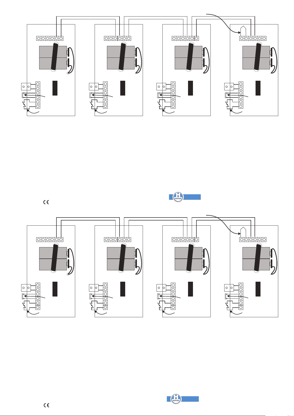
GX20e
IMPORTANT
the
E.O.L.
link
is
only
used
on
last
unit
or
when
units
are
not
wired
together
SSoouunnddeer
BBuuzzzzeer
The
Gemini
independantly
Installation
GX20e
the
other
black
flash
inserting
condition.
SILENCE.
seconds.
Installation
A A two
run
before
disconnect
the
each
interconnected.
Dw:
is
front
panel
suitable
leads.
alternate
the
wire
through
making
last
unit
unit
60083
as
supplied
Switch
The
The
Remove
Interconnected.
connection
all
the
must
in
turn
Iss
E EO OL L
p pi il le es s
KKeeyyssWwititcch
InInteterrrruuppteteuur
GX20e
is
powered
Standalone
with
and
fix
the
form
of
fixing.
to
Fire
Fault.
black
plastic
sounder
Fire
LEDs
the
units
as
the
interconnections.
batteries
have
as
outlined
Jun
I IN N
A Al lk ka al li in ne e B Ba at tt te er ri ie es s
2 2 x x 9 9 v vo ol lt t
p
CCaallll PPooinint
PPooinintdtd'a'appppeel
intended
from
two
Unit
two
operating
Back
Ensure
SILENCE
Return
Test
will
sounder
will
flash
Test
Key
is
required
shown
and
make
the
EOL
above.
O OU UT T
T
y
-
W
r
a
as
9v
box
BATTERY
the
Key
in
and
between
above.
the
link.
standalone
PP3
keys,
to
any
that
an
Keyswitch
to
the
and
the
and
the
restore
It
is
Once
two
Starting
It
is
not
size
Alkaline
TEST
solid
surface
EOL
link
TEST
to
underside
fire
LEDs
sounder
the
keyswitch
each
unit.
best
to
install
it
is
confirmed
wire
connections
with
recommended
SSoouunnddeer
BBuuzzzzeer
battery
batteries.
key,
batteries
using
is
fitted.
the
sounder
RE-START
of
the
will
flash
will
give
to
It
is
NOT
each
that
the
end
of
powered
and
the
screws
Clip
the
NORMAL.
call
point,
alternately.
short
its
NORMAL
possible
unit
and
each
as
shown.
line
unit
that
more
E EO OL L
p pi il le es s
KKeeyysswwititcch
InInteterrrruuppteteuur
fire
fixing
batteries
will
sound
this
warning
test
unit
refit
than
I IN N
A Al lk ka al li in ne e B Ba at tt te er ri ie es s
2 2 x x 9 9 v vo ol lt t
p
CCaallll PPooinint
PPooinintdtd'a'appppeel
alarm.
screws
provided
and
est
will
Turn
bleep
position.
to
spur
it
as
functions
DO
NOT
the
batteries
four
O OU UT T
T
y
-
W
r
a
Each
etc.Remove
or
on
to
the
the
the
fire
simulate
the
Keyswitch
every
off,
the
standalone
correctly
FORGET
units
unit
with
red
LEDs
Alarm
an
circuit
and
are
SSoouunnddeer
BBuuzzzzeer
A A cable
The
is
some
and
will
alarm
30
must
unit
that
test
batteries
need
to
Visual
Indications
FIRE
SILENCED
SILENCED
By
BATTERY
to
Audible Warning
FIRE
SIILENCED
SILENCED no Fire Condition
BATTERY
fault
be
replaced
after
no
LOW
LOW
and
should
Fire
after
E EO OL L
I IN N
p pi il le es s
A Al lk ka al li in ne e B Ba at tt te er ri ie es s
2 2 x x 9 9 v vo ol lt t
CCaallll PPooinint
PPooinintdtd'a'appppeel
KKeeyysswwititcch
InInteterrrruuppteteuur
battery
last
then
Fire
Condition
or
cable
Fire
or
cable
O OU UT T
T
y
-
W
r
a
p
fault
monitor
is
for
both
fault
fault
at
included
least
12
months
should
be
replaced.
red
Two
LEDs
red
Two
LEDs
red
Alternate
amber
Flashing
amber
Flashing
Continuous
Bleep
Continuous (for audibility walk test)
Single
Bleep
Sounder
every
30
bleep
every
every
60
Hoyles Electronic Developments Ltd
T. 01744 886600 F. 01744 886607 E. sales@hoyles.com W. www.hoyles.com
SSoouunnddeer
BBuuzzzzeer
to
detect
depending
flashing
flashing
amber
LED
LED
at
LED
every
seconds
seconds
seconds
cable
on
the
alternately
together
if
battery
sec
intervals
60
E EO OL L
I IN N
p pi il le es s
A Al lk ka al li in ne e B Ba at tt te er ri ie es s
2 2 x x 9 9 v vo ol lt t
-
W
r
a
p
CCaallll PPooinint
PPooinintdtd'a'appppeel
KKeeyysswwititcch
InInteterrrruuppteteuur
disconnection
frequency
every
30
is
healthy
if
battery
seconds
if
battery
is
low
O OU UT T
T
y
or
of
testing.
seconds
short
is
low
circuit.
If
batteries
GEMINI
The
Gemini
independantly
Installation
GX20e
is
supplied
the
front
panel
other
suitable
black
leads.
flash
alternate
inserting
the
condition.
The
SILENCE.
seconds.
Remove
Installation
two
wire
run
through
before
making
disconnect
the
last
unit
each
unit
in
interconnected.
Dw:
60083
GX20e
r
r
GX20e
is
powered
as a a
Standalone
with
and
fix
the
form
of
fixing.
Switch
to
SILENCE & &
Fire & &
Fault.
black
plastic
sounder
The
Fire
LEDs
the
Test
Interconnected.
connection
the
Iss
all
units
as
the
interconnections.
batteries
must
have
turn
as
outlined
Jun 0303
is
intended
from
two
two
operating
back
Ensure
Return
Test
will
sounder
will
Key
required
shown
and
make
the
EOL
above.
IMPORTANT
T
y
-
W
r
a
p
t
l
h
r
as a a
standalone
9v
PP3
Unit
keys, a a
box
to
any
that
BATTERY
the
keyswitch
Key
in
to
the
and
flash
and
the
and
restore
between
above.
It
is
Once
the
two
link.
Starting
It
is
size
Alkaline
TEST
solid
surface
an
EOL
link
TEST - -
underside
the
fire
LEDs
sounder
the
keyswitch
each
unit.
best
to
it
is
confirmed
wire
connections
with
not
recommended
the
E.O.L.
battery
batteries.
key,
batteries
using
is
fitted.
the
sounder
to
RE-START & &
of
the
will
flash
will
give a a
to
It
is
NOT
install
each
that
the
end
link
r
powered
the
Clip
call
alternately.
short
its
NORMAL
possible
unit
each
as
shown.
of
line
that
more
is
only
r
fire
and
fixing
screws
the
batteries
will
sound
NORMAL. TT
point,
this
warning
to
and
test
unit
functions
DO
unit
refit
than
used
T
y
-
W
r
a
p
h
alarm.
screws
provided
on
and
est
will
simulate
Turn
the
bleep
position.
spur
off,
it
as a a
NOT
the
batteries
four
units
on
last
t
l
r
Each
unit
etc.Remove
or
with
to
the
red
the
LEDs
the
fire
alarm
an
Keyswitch
every
the
circuit
standalone
correctly
FORGET
and
are
unit
or
when
units
cable
The
is
some
and
will
alarm
30
must
unit
that
test
batteries
need
to
Visual
Indications
FIRE
SILENCED
SILENCED
by
BATTERY
to
Audible Warning
FIRE
SIILENCED
SILENCED no Fire Condition
BATTERY
r
fault
be
replaced
after
no
LOW
LOW
are
r
and
should
Fire
after
not
wired
battery
last
then
Fire
Condition
or
cable
Fire
or
cable
together
T
y
-
W
r
a
p
t
l
h
r
fault
monitor
is
for
both
fault
fault
at
included
least
12
months
should
be
replaced.
red
Two
LEDs
red
Two
LEDs
red
Alternate
amber
Flashing
amber
Flashing
Continuous
Bleep
Continuous (for audibility walk test)
Single
Bleep
Sounder
every
30
bleep
every 2 2
every
60
Hoyles Electronic Developments Ltd
T. 01744 886600 F. 01744 886607 E. sales@hoyles.com W. www.hoyles.com
to
detect
depending
flashing
flashing
amber
LED
LED
at 2 2
LED
every
seconds
seconds
seconds
r
r
cable
on
the
alternately
together
if
battery
sec
intervals
60
-
W
r
a
p
h
disconnection
frequency
every
30
is
healthy
if
battery
seconds
if
battery
is
low
T
y
t
r
or
of
testing.
seconds
l
short
is
low
circuit.
If
batteries
 Loading...