

Page 1
Door Switch Contact Rd/Yl
EX204 Battery powered for use where a 4. OUT OF THE BOX factory default settings
separate supply of power is not available and are suitable for most applications. On first use
the protected door is opened infrequently or we recommend that you use these settings to
there is no requirement to sound the sounder test the EXITGUARD. They can be changed
for long periods. Can be powered from 12vdc if later to suit local requirements. Test by entering
necessary. (Discard batteries)
the user code and pressing I for Chime Mode.
A chime will be heard each time the door is
EX205 12vdc powered for use where the
opened.
protected door may be opened frequently or
Advanced Installation
the integral sounder needs to sound for
The following parameters can be changed
protracted periods. This version can also be
through the keypad:
interfaced with other equipment. There are volt
1. User Code
free relay contacts to separately signal
2. Select one of six different alarm tones
ON/OFF status and alarm conditions at remote
3. Change auto re-arm delay 0 - 88 secs
points. Cannot be powered from batteries.
4. Change Door Open Too Long (DOTL1)
EX206 230vac powered version where the
delay for keypad reset mode 0 secs - 88 mins.
protected door may be opened frequently or
5. Change DOTL2 delay for auto reset mode
the sounder needs to sound for protracted
0secs - 88mins.
periods. There is a volt free alarm relay contact.
6. Switch Bleep In Off (BIO) on or off.
This version is supplied with 6 x AA alkaline
7.Add or change a Reset/Pass Code
batteries for standby - Note: the batteries will
8. Add or change a Manager Code.
not power the alarm relay.
OUT OF THE BOX User Operation.
All versions have key pad control, integral
There are four possible modes:
sounder with programmable tones, 5 mode
Off Mode
LEDs, a front/back acting tamper switch and a
Chime Mode I
logic output to signal to a MULTIGUARD
Keypad Reset Mode II
indicator from HED. All are supplied with a door
Auto re-arm Mode III
contact, fixing screws and door warning label.
Quick Install
When the User Code is entered the
EXITGUARD is interrogated and one of the
EXITGUARDS are NOT intended for external
mode LEDs illuminates to indicate the current
use and to avoid damage should not be fixed to
status.
the protected door itself.
After the User Code is entered there is a 5sec
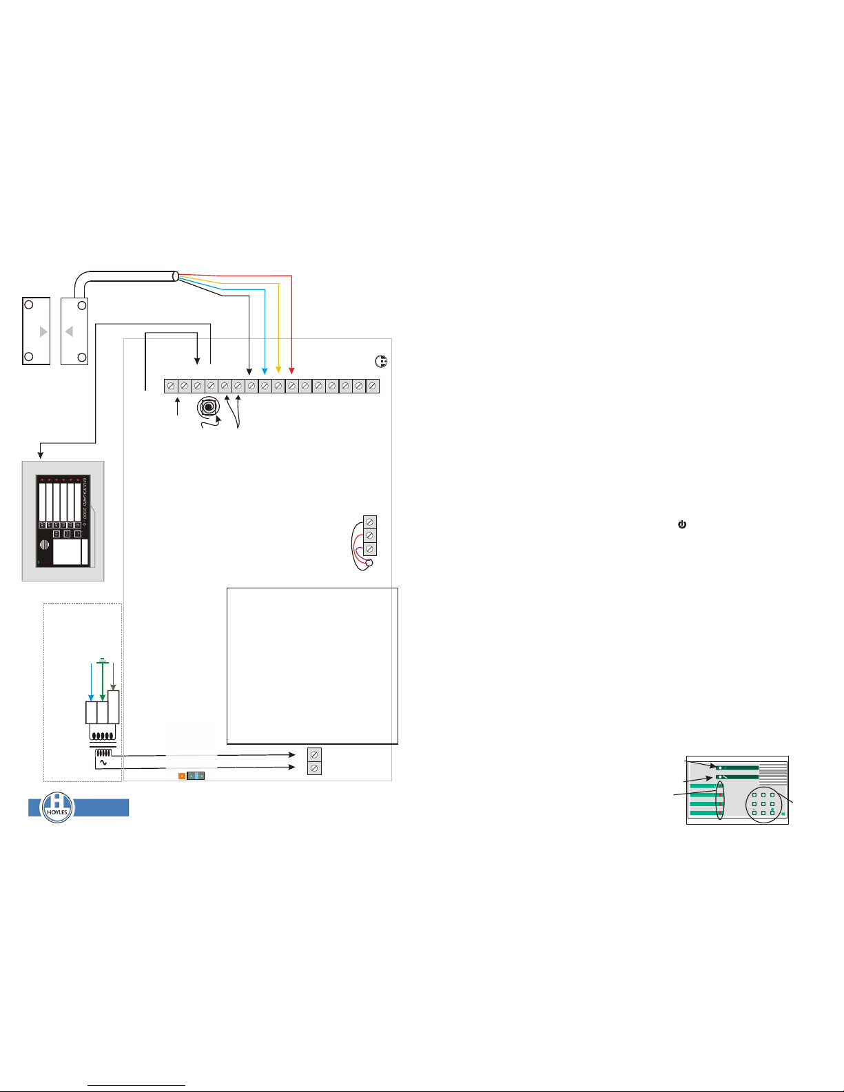
1.The door contact is in two parts; the magnet
window to change the mode, eg. If the current
should be fixed to the door and the contact with
mode is OFF and it is desired to switch to the
its cable fitted to the frame. The cable should
Keypad Reset mode just enter II ie 2 on the
be taken to the EXITGUARD and connected as
keypad. Within 5secs the LED will extinguish. If
shown. A is the alarm input for the switch
a mistake has been made this can be rectified
element (RD/YL) of the contact and T is from
before the LED extinguishes by simply
the tamper loop (BL/BK) of the contact.
selecting the desired mode, the LED indication
2. Make all connections, apply power, a double
will change to the new mode.
bleep will be heard and the four mode LEDs will
If the Auto re-arm mode is selected then the
illuminate.
factory default period of 30secs will be used
3. When the EXITGUARD leaves the factory
unless set up differently. (see programming
there are no codes in memory. The four
instructions to change the Auto re-arm period
illuminated red LEDs are inviting you to
and other functions)
enter a User Code. This must be a four digit
memorable code. As the code is entered
acknowledge bleeps are heard and each of
the mode LEDs will extinguish. The code is
now stored in memory and the EXITGUARD
will emit a double bleep and should be in the
OFF mode.
BK RD PP
HED
Door Switch tamper
loop Bl/Bk
These relay contacts
change state when the
EXITGUARDis armed.
EX205 only.
These relay contacts
change state when an
alarm condition is
generated.
EX205 & EX206
16vac
M
R
ve
+ve-
To
These terminals
are only used on
EX204 & EX206
If required the tamper switch To can be:
a. wired in series with the Blue or Black door switch
tamper loop to give an audible alarm at any time.
b. wired in series with the Red or Yellow of the door
switch contact pair to give an alarm condition only
when the Exitguard is armed.
c. wired to a remote device to give a warning at a
remote location.
d. ignored and not connected at all.
The on board tamper switch is
connected to these two terminals, To
If the tamper switch is required fit the spring
ensuring contact with the wall when the lid is fitted,
and operates when the lid is removed.
A
T
12vdc
EX204 Apply 12vdc (140ma max) here if required.
EX205 Apply 12vdc (165ma max) here.
EX206 12vdc available here @ 100ma max when mains power is available.
EXITGUARD EX200 series Installation Instructions
RELAY 1 RELAY 2
Input for Fire Door Checker (see scenario 4) Or Temporary Pass through (see scenario 7)
Apply 12vdc +ve to invoke Fire Door Checker. This can be
derived from an intruder, time clock or keyswitch etc..
Apply momentary 12vdc +ve for return pass through.
Factory Default.
To restore the factory default settings
disconnect power completely for about 10
secs. Ensure the door contact & tamper loop
are open. Move the SYSTEM RESET
jumper J1 from its normal position to the
reset position. Re-apply power four bleeps
will be heard. Replace the jumper to the
normal position. Two beeps will be heard
and the four mode LEDs should be
illuminated inviting you to enter a new user
code. Re-close the tamper & door contact..
The Factory default settings are as follows:
User Code None
Auto re-arm period 30 seconds
DOTL1 delay 00 seconds
DOTL2 delay 00 Seconds
Sounder Tone 1
I
II
III
Chime mode
Off
Keypad reset mode
Auto re-arm mode
exitguard
Mode
LEDs
Power LED
Setup LED
NO
COM
NC
NO
COM
NC
SYSTEM J1
RESET
{
Z1
Z2
Z3Z4Z5
Z6
F3
MULTIGUARD 2000 - 6
O/P to optional MULTIGUARD
Neutral
Earth
1 AM
P
230vac
Transformer is fitted in the enclosure back
box and is pre-wired to the circuit board.
EX206 Mains Powered Version Only
DWG No: 60112 Issue 2, Nov 2013
1
4 5 6
7 8 0
2
3
II IIII IIIIII
Keypad
T. 01744 886600 F. 01744 886607 E. sales@hoyles.com W. www.hoyles.com
Hoyles Electronic Developments Ltd
NORM
RESET
8mm (max gap)
Magnetic Door Contact.
Fit to door frame and
protect from moisture
Magnet. Fit to door
& align with contact
Page 2
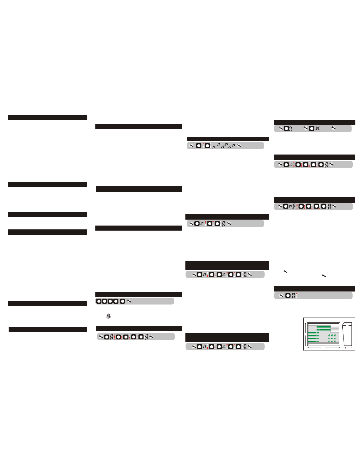
EXITGUARD Set-up
Bleep In Off (BIO).
Scenario 6. Temporary Pass Through
Tone Select.
Add or change a Reset/Pass Code.
Scenario 1. Typical Fire Exit Door.
High Level Security.
Add or Change a Manager Code.
Scenario 2. Shop or Reception Door.
Auto re-arm period.
Programming.
Scenario 3. Fire Door Checker.
Door Open Too Long Delay for Keypad
reset mode (DOTL1.)
Leave Set-up Mode.
To Enter Set-up Mode.
Scenario 4. Loading Bay Door.
Changer User Code.
Scenario 5. Fire Stop Corridor Door.
Door Open Too Long Delay for Auto re-arm
Mode (DOTL2.)
closer spring is fitted. Arm the EXITGUARD in III code is pressed an LED will extinguish. When the to the procedure for DOTL1 above
mode. code is complete a double bleep is heard. The unit
The EXITGUARD contains a non volatile memory
remains in the SET-UP mode and further
(NVM). The User Code and any programmed
programming can be carried out following the
functions are stored in this NVM even if power is
instructions below.
lost for long periods. If you have forgotten the
In Set-up mode BIO can be toggled On and Off .
User Code (or manager code if used) it will be
The default factory setting is Off,
necessary to reset to the factory default settings.
In Set-up mode enter 6. If one bleep is heard then
Any functions that you have programmed will be
BIO is off, if two bleeps are heard then BIO is on.
lost.
In Set-up mode enter 2. A bleep is heard and a
Successively pressing 6 will toggle BIO on and off.
Before altering any functions such as the re-arm
single mode LED illuminates to indicate that a one
period or door open too long delays (DOTL) etc..
digit number in the range 1 - 6 is needed.
consider if the factory defaults will meet your
The tones are:
requirements. The following scenarios are quite
1 & 2. High (Factory default setting is 1)
In set-up mode enter 7. A single bleep is heard and
typical. The first four involve no programming
Ear defenders are recommended!!!!!
four mode LEDs illuminate inviting you to enter a
other than setting the User Code. The remaining
3 & 4. Normal
four digit Reset/Pass Code PPPP. As each digit is
scenarios require a little programming.
5 & 6. Low entered an LED will extinguish. When the code is
complete a double bleep is heard. The Set-up LED
If an incorrect digit is entered a ‘Barp’ will be heard
An audible alarm is required when the door is
continues to flash to indicate that you are still in the
and the LED continues to indicate that a single digit
opened. Use the factory default settings and arm
In some applications it may be necessary to allow only
Set-up mode. Ensure DOTL1 and DOTL2 are set.
is still required. When a correct digit is entered the a
selected persons to change the various parameters. A
the EXITGUARD for either Keypad reset II or
short sample of the tone is played with the strobing
Manager Code gives an extra level of security by only
Auto re-arm III mode. ie. the EXITGUARD
LEDs to indicate the selected tone. The Set-up LED
allowing a manager to change:
silences and re-arms after a 30 second delay if the
flashes to indicate that you are still in Set-up mode.
A. User and Pass & Manager Codes
door has been closed.
Enter 0 to leave if set-up is complete.
In set-up mode enter 8. a triple bleep is heard and
B. Bleep In Off (BIO)
four mode LEDs illuminate inviting you to enter a
C. Auto re-arm delays
A chime is required each time the door is opened.
four digit Manager Code MMMM. As each digit is
Use the factory default settings and arm the
D. Door Open Too Long delays (DOTL)
entered an LED will extinguish. When the code is
EXITGUARD for Chime I mode.
complete a double bleep is heard. To change any
In Set-up mode enter 3. A bleep is heard and two
Before the EXITGUARD can be programmed a User
further settings in future you will need to use the
mode LEDs will illuminate to indicate that a two digit
Code must have been set up as detailed overleaf. The
The EXITGUARD can be used to verify that all
Manager Code in order to enter the set-up mode
number corresponding to the required period eg. 00
following functions can be programmed into the NVM:
Fire Exit Doors are available for use when a
rather than the User Code.
for instant re-arm, 05 for 5secs, 88 for 88secs etc..
building is occupied. The R terminal of each
1. Four digit User Code.
As the digits are entered the LEDs extinguish and a Note: If the EXITGUARD has been set up with a
EXITGUARD is connected to a switched +ve
2. Select one of six different alarm tones
double bleep is heard when both digits have been Manager Code then both the User Code and
12vdc of the building’s intruder alarm. When the
3. Change auto re-arm time 0 - 88 seconds
entered. The Set-up LED continues to flash to Manager Code must be used to enter the set-up
alarm is set this signal is applied to the
4. Change DOTL1 delay for keypad reset mode 0 indicate that you are still in the Set-up mode. mode and change any settings. Proceed as
EXITGUARDs. When the intruder alarm is un-set
seconds - 88 minutes. follows:
the signal is removed and the EXITGUARDs will
5. Change DOTL2 delay for auto reset mode 0 Enter the User Code UUUU, Press and hold 7.
strobe and double bleep every 30 secs. Opening
seconds - 88 minutes. The LED illuminates steady. Enter the
and re-closing the door causes the strobing and
Manager Code M M M M, the LED flashes.
6. Switch Bleep In Off (BIO) on or off.
the periodic bleeps to cease. The EXITGUARD
To delete a Pass or Manager Code use the User
7.Add or change a four digit Reset/ Pass Code.
In Set-up mode enter 4. A bleep is heard and the
then automatically reverts to the mode it was set to
Code for either or both..
8. Add or change a four digit Manager Code.
bottom two mode LEDs illuminate to request a two
during the previous period of occupancy; O, I, II
Programming is carried out in Set-up mode digit number for minutes eg. 00 for zero mins 05 for
or III. If the intruder alarm has been set in error it
5mins, 88 for 88 mins etc.. As the digits are entered
can be un-set and re-set without the necessity to
the LEDs extinguish and a single bleep is heard
open and re-close all doors for checking.
when both digits have been entered. The top two
In Set-up mode enter 0, a double bleep is heard as the
mode LEDs now illuminate requesting a two digit
EXITGUARD leaves set-up mode. The EXITGUARD
To enter the this mode type the User Code UUUU and
Invoke the Bleep In Off facility (see programming
will now be in the OFF mode as indicated by the OFF
number for seconds eg. 00 for zero secs, 15 for
hold down the 7 key until two beeps are heard. The
below). Arm the EXITGUARD in Keypad reset II
LED. Whilst this LED is illuminated the EXITGUARD
15secs up to a maximum of 58secs. The maximum
Set-up LED flashes. To leave this mode type 0. The
mode. Switch Off with keypad for deliveries. The
can be switched
is therefore 88m58s. A double bleep is heard when
system always reverts to the OFF when leaving Set-
Bleep In Off will remind staff to re-arm the
to any other mode
all digits have been entered correctly. The Set-up
up. See also Manager Code later.
EXITGUARD after each delivery.
I, II or III or
LED continues to flash to indicate that you are still in
even back to Set-
the Set-up mode.
up mode by
Staff are able to pass through the door without
pressing and
generating an alarm but if left open then an alarm
holding 7.
will be generated. Set the Auto re-arm period at 00
In Set-up mode enter 1, a double bleep is heard and
and DOTL2 delay at 10. Door must be closed
the four mode LEDs will illuminate inviting you to enter
within 10 seconds. It is recommended that a door
a new four digit User Code UUUU. As each digit of the
In Set-up mode enter 5. The procedure is identical
In this scenario a Pass Code is used to allow passage
through to say a storeroom without the necessity to
switch the EXITGUARD Off. When using a pass code
there is a 10 sec window to open the door and a further
time period to pass through and close the door. This
time is specified by either DOTL1 or DOTL2,
depending on which mode the EXITGUARD is armed
in. To use a pass code DOTL1, DOTL2 or both must be
set depending on whether you wish to use mode II or
III. See later instructions for setting DOTL1 and
DOTL2. To return through the door a momentary +ve
must be applied to the R terminal, this will bleep the
unit and strobe the LEDs to warn that the door is about
to open. Arm the EXITGUARD in mode II or III.
?
?
?
?
?
?
?
?
?
?
?
?
?
? ?
7
3
6 6
4
5
2
BIO BIO
PP
O
UPU
PUPUP
1
7
8
0
M M M M
Chime mode
Off
Keypad reset mode
Auto re-arm mode
1
4 5 6
7 8 0
2
3
exitguard
Dimensions mm
125
175
60
50
DWG No: 60112 Iss 3 Sep 2014
 Loading...