

Page 1

Zoneguard ZG800 Installation Instructions
ZONEGUARD is a Grade 3 EN50131-3:2009
Environmental Class II zone omit unit that fits
between intruder detection devices and a control
panel to allow the devices to be securely and safely
omitted and reinstated.
In its simplest mode ZONEGUARD uses its integral
keyswitch to omit or reinstate. Other modes are
available using the integral keypad or external
devices such as biometric reader or a combination of
keyswitch and keypad, useful where dual
responsibility is needed. Timed entry/exit modes are
also available.
The ZONEGUARD requires a supply of 12vdc.
(120ma quiescent - 200ma peak)
General Rules
A. Zones will always omit using an omit function.
B. If any zone has a detection condition during
reinstatement, then it must be returned to omitted
state and the detection condition cleared and then
reinstated.
When powered, no indications should be seen. If the
unit should bleep and LED III indicates then the
memory has been corrupted and the unit will require
setting up.(See ‘set/change mode’ instructions)
The NVM (Non Volatile Memory) remembers how
the unit was previously set up, including the code, if
used, after a power down.
There are seven operational modes:
1.Integral keyswitch mode. (Factory default)
2. Integral keypad mode.
3.Remote latching input mode, eg. keyswitch
4. Remote non-latching input mode, eg.
biometric).
5.Combination of integral keypad & integral
keyswitch.
6.Timed entry/exit, integral keyswitch execute.
7.Timed entry/exit, integral keypad execute.
Operational instructions
To omit the zones Mode 1 turn the unit keyswitch to position R. In any mode, if the alarm zones are not clear for reMode 1 turn the unit keyswitch to position O. Mode 2 type in the 6 digit code.
Mode 2 type in the 6 digit code. Mode 3 operate the remote device
Mode 3 operate the remote device Mode 4 operate the remote device
Mode 4 operate the remote device Mode 5 type in the 4 digit code and the unit will bleep
Mode 5 type in the 4 digit code and the unit will bleep
for approx. 10 seconds. During this time turn the unit
keyswitch to position O. Mode 5 alternative operation. Turn the keyswitch to
Mode 5 alternative operation. Turn the keyswitch to
position O and while it is there type in the 4 digit code. Mode 6 turn the keyswitch to position O the unit will
Mode 6 open the start timer contact and the unit will
bleep for the entry/exit time. While the timer is timing,
turn the keyswitch to position O.
Mode 7 open the start timer contact and the unit will
bleep for the entry/exit time. While the timer is timing,
type in the 6 digit code.
Omit Indications
In any mode, when the zones are omitted, a double
bleep will sound.
To reinstate the zones
for approx. 10 seconds. During this time turn the unit
keyswitch to position R.
position R and while it is there type in the 4 digit code.
bleep for the entry/exit time. While the timer is timing
you can open and close the start timing contact, but if
it is open at the end of the entry /exit time, it will
indicate fault.
Mode 7 type in the 6 digit code, the unit will bleep for
the entry/exit time. While the timer is timing you can
open and close the start timing contact, but if it is open
at the end of the entry /exit time, it will indicate fault.
Reinstate indications
In any mode, when the zones are re-instated, a long
single bleep will sound.
instating, or in modes 6 and 7 the entry/exit start
contact is open, then the tone will not silence after 2
seconds, but continue to indicate that all is not well. In
addition to the sounder, an led will indicate the source
of the problem, either alarm zones 1 and 2 (LED I and
LED II), or the entry/exit start ting contact LED III.
If a fault is indicated, then you must omit the zones
again. The led indication will remain until the source
of the fault is cleared, then the led indication will clear
and re-instating can be attempted again.
User Code Changing from the keypad
An authorised user, can change the code from the
keypad, but only if the zones are not omitted. To
change the code, simultaneously press 0 and 1 a
double beep will sound and three LEDs will be
illuminated. Enter the current code, a double beep will
sound and LED I will extinguish LEDII and LEDIII will
remain illuminated. Enter the new code. A double
beep will sound, LEDII and LEDIII will extinguish.
The change must be completed within 30 secs.
Set / change mode instructions
The ZONEGUARD will work out of the box in mode 1 operational position B. bleeps will sound LEDI will extinguish leaving LEDII
without any set up. All setting/changing the mode and ledIII illuminated. Type in your six digit code. Two
operations must be carried out with the key in the R bleeps will sound and LEDII will extinguish. LEDIII will
position. To set up the unit or change modes move remain illuminated and the unit will bleep until J1 is
jumper J1 to the set position A. Two bleeps will sound moved to the operational position B.
and three LEDs illuminated. Next, enter the required
mode number:
Mode 1 press 1. Two bleeps will sound and LEDI and 0 for neither or press 1 for zone 1 only or press 2 for
LEDII will extinguish. LEDIII will remain illuminated both zones to sound alarm tone. Two bleeps will
and the unit will bleep until J1 is moved to the sound LEDI and LEDII will extinguish. LEDIII will
operational position B. remain illuminated and the unit will bleep until J1 is
Mode 2 press 2. Two bleeps will sound and LEDI will
extinguish. LEDII and LEDIII will remain illuminated. Mode0 press 0. Two bleeps will sound and LEDI will
Type in your six digit code. Two bleeps will sound and flash. LEDII and LEDIII will remain illuminated. Press
LEDII will extinguish. LEDIII will remain illuminated 0 for no bleep while omitted or press 1 to enable bleep
and the unit will bleep until J1 is moved to the while omitted. Two bleeps will sound LEDI and LEDII
operational position B. will extinguish. LEDIII will remain illuminated and the
Mode 3 press 3. Two bleeps will sound and LEDI and
LEDII will extinguish. LEDIII will remain illuminated
and the unit will bleep until J1 is moved to the
Mode 4 press 4. Two bleeps will sound and LEDI and
LEDII will extinguish. LEDIII will remain illuminated
and the unit will bleep until J1 is moved to the
operational position B.
Mode 5 press 5. Two bleeps will sound and LEDI will
extinguish. LEDII and LEDIII will remain illuminated.
Type in your four digit code. Two bleeps will sound
and LEDII will extinguish. LEDIII will remain
illuminated and the unit will bleep until J1 is moved to
the operational position B.
Mode 6 press 6. Two bleeps will sound and LEDI will
flash. LEDII and LEDIII will remain illuminated. Type
in the entry/exit time in seconds(two digits) two
bleeps will sound LEDI and LEDII will extinguish.
LEDIII will remain illuminated and the unit will bleep
until J1 is moved to the operational position B.
Mode 7 press 7. Two bleeps will sound and LEDI will
flash. LEDII and LEDIII will remain illuminated. Type
in the entry/exit time in seconds(two digits) two
Mode8 press 8. Two bleeps will sound and LEDI will
flash. LEDII and LEDIII will remain illuminated. Press
moved to the operational position B.
unit will bleep until J1 is moved to the operational
position B.
Additional features
Remote Re-Instate This relay follows the Zoneguard state at all times and Bleep While Omitted programmed as mode 0. While
It is possible to re-instate the zones from a remote
device (Control panel, central station, time clock etc).
Apply a momentary +ve to RMT2. If the zones have Remote Sounder Output.
been omitted by the keyswitch or a latching device Omitted Door Alarm. Programmed as mode 8. While
connected to RMT1 LED III will illuminate to warn that the Zoneguard is omitted the alarm sounds for the
the zones are re-instated but the keyswitch is not in duration that a alarm zone is open. Programming
the correct position. To rectify this turn the keyswitch options are neither, zone 1 only or zone 1 and zone 2.
to the re-instate position. The default is neither.
Omitted Relay
could be used to signal the status to a main control or the Zoneguard is omitted the sounder double bleeps
central station. The contacts are rated 30vdc 1A . every 30 seconds. Programming options are on or off.
The default is off.
An open collector sounder output is provided to drive
remote sounders (12vdc 100ma max). This output
sounds omitted and reinstated tones.
Zoneguard Sounder Control Input.
Apply closed circuit from other equipment to sound
the alarm sounder at any time omitted or reinstated.
DWG 60099.cdr Iss Nov 12
Page 2
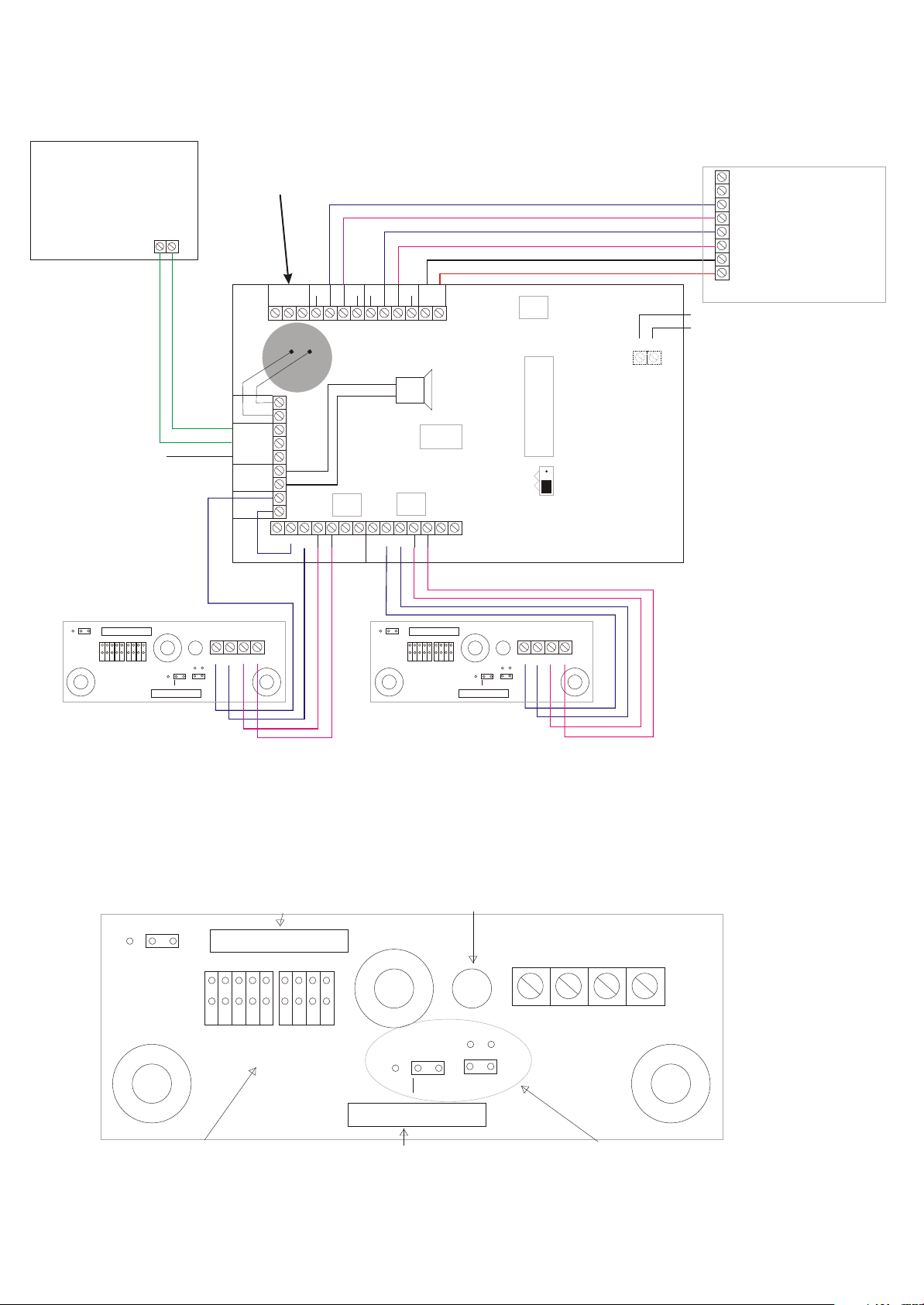
Configuration for Grade 3 Door Contact Hoyles DCS/G3
Remote device for modes
3 and 4 eg a normally open
remote keyswitch or biometric
reader. In modes 6 and 7 this
would be a device to start the
timer. It is not part of the
alarm monitoring
Optional remote re-instate.
Apply a momentary +ve
These contacts can be taken to a
remote point or data logger to
indicate or record zone omissions.
TO
PANEL
KSW
RMT 1
R COM
RMT 2
SDR
DETECTION 2
NO
OMITTED
-
+
Z2
NC
C
UNIT
TAMPER
X2
Y2
C2
A2
T2
A2
-
+
Z1Y1X1
T1C1A1
ZONE 3
ZONE 2
CONTROL
ZONE 1
PANEL
12v dc
POWER
-
-
+
TO
+
PANEL
Apply closed circuit from remote
equipment to sound the alarm
F +
OPTIONAL
REMOTE
+
SOUNDER
tone while the signal is applied
The unit tamper is wired
as Zone 2 tamper
PROGRAMMING MODE
A
OPERATIONAL MODE
B
J1
Unused alarm loops on the
detection side must be linked
with a short circuit not a resistor.
-
+
A1
DETECTION 1
Mag
Tamp
Byps
A
EOL
Alarm
W
Y
H
Std
X
Z
Tamp
Alarm
Mag
Tamp
Byps
A1
1B
B2
2C
C3
3D
D4
5
EOL
Alarm
W
Y
H
Std
X
Z
Tamp
Alarm
Door Contact DCS/G3 Door Contact DCS/G3
Grade 3 Door Contact Hoyles DCS/G3
Tamper Reed Tamper Switch
Mag
Tamp
Byps
3
4455
Alarm
1
2
A
B
C
D
EOL
W
Y
H
Std
Tamp
X
Z
Alarm
Select Alarm and
EOL jumpers to
suit control panel
Alarm Reed Control Jumpers
Must be set as shown
(W-X none) (Y-Z on)
and (H on)
Page 3

Zone omit theory
The main reason to use a Zone Omit Module, is to isolate a 24 hour protected zone from a security system without having full
access to the security system and having isolation rights. It is NOT a local alarm.
One way to isolate a device is to short circuit the monitoring contact, so that when the monitored contact opens it appears as closed
to the system. The simplest way of doing this is with a low cost keyswitch. However with just a keyswitch, an open contact will
switch back onto the security system and cause a false alarm if accidentally left open when switching back. The zone omit module
ensures that this does not happen and gives a local warning if you attempt to reinstate the open omitted device.
The Zoneguard ZG800 achieves this and does not isolate tampers thus allowing end of line monitoring by the security system.
Classic fully supervised loopFully supervised loop with ZG800 zone omit
A1(2)
Shunt
Switch
ZG800
The EOL is always monitored by the intruder alarm electronic circuitry. When the shunt switch of the ZG800 is switched,
the ZG800 circuitry starts to monitor the alarm loop (A1 or A2). This is why it is essential that there are no electrical
connections external to the ZG800 between the Alarm loop and the EOL loop. Connections include resistors and links.
The ZG800 alarm loop monitoring is required to prevent faults from being reinstated onto the security system.
Any connections to the X and Y terminals pass through the Zoneguard without interference eg EOL and anti-mask. Anything
across the ‘A’, terminals gets omitted.
A1(2)C1(2)
X1(2)
Y1(2)
Resistor Resistor
EOL EOL
Double Doors with DCS/G3 contacts (Only one zone shown for clarity)
POWER
TO
PANEL
KSW
RMT 1
R COM
RMT 2
SDR
NO
OMITTED
-
+
Z2
NC
C
UNIT
TAMPER
X2
Y2
C2
T2
A2
Contact 1 Contact 2
Mag
Tamp
Byps
No Alarm
Jumpers set
A A1 1B B2 2C C3 3D D4 45 5
EOL EOL
Alarm Alarm
W W
Y Y
H H
Std Std
Set EOL No EOL
Alarm Alarm
Tamp Tamp
X X
Z Z
Control
Jumpers
C1
A2
T1
-
+
Y1
Z1
X1
No Alarm
Jumpers set
TO
-
A1
+
PANEL
F +
OPTIONAL
REMOTE
+
SOUNDER
PROGRAMMING MODE
A
OPERATIONAL MODE
B
J1
-
+
A1
Alarm shunt resistor to suit control panel
Mag
Tamp
Byps
Control
Jumpers set
Jumpers
Unused zones
Z2
NC
C
UNIT
TAMPER
X2
Y2
C2
A2
T2
-
A2
+
Z1
TO
PANEL
RMT 1
R COM
RMT 2
SDR
KSW
NO
OMITTED
-
+
POWER
C1
T1
TO
-
A1
+
PANEL
Any unused alarm loop on the detection side must be linked out.
This is required is for the Zoneguard to be allowed to reinstate.
F +
OPTIONAL
REMOTE
+
SOUNDER
The Zoneguard provides a local warning if a zone is not secure
when you try to reinstate it onto the security system. It will leave
both zones omitted if a fault is present. Normally the closed loop
comes from a closed door or a detector that is not detecting. In the
case of an unused zone, the loop allows the Zoneguard to
PROGRAMMING MODE
A
OPERATIONAL MODE
B
J1
-
Y1
+
X1
A1
reinstate the other used zone (if it is clear).
Page 4

Note the unit sounder indicates faults when reinstating. It is NOT a local alarm sounder.
Remote device for modes
3 and 4 eg a normally open
remote keyswitch or biometric
reader. In modes 6 and 7 this
would be a device to start the
timer. It is not part of the
alarm monitoring
Optional remote re-instate.
Apply a momentary +ve
Device 2
eg PIR
These contacts can be taken to a
remote point or data logger to
indicate or record zone omissions.
NO
C
OMITTED
-
UNIT
TAMPER
Y2
Z2
A2
C2
A2
T2
NC
X2
ALR
-
T1
-
A2
+
Z1
+
TO
PANEL
KSW
RMT 1
R COM
RMT 2
SDR
DETECTION 2
AMR
EOL
T2
M2
+
ZONE 3
ZONE 2
CONTROL
ZONE 1
PANEL
12v dc
POWER
C1
TO
-
A1
+
PANEL
F +
OPTIONAL
REMOTE
+
SOUNDER
+
Apply closed circuit from remote equipment to
sound the alarm tone while the signal is applied
CONFIGURATION FOR EOL
WITH TAMPER AND ANTI-MASK
NOTES
PROGRAMMING MODE
A
OPERATIONAL MODE
B
J1
-
X1
AMR
+
A1
DETECTION 1
EOL
ALR
A2
T2
M2
-
+
Device 1
eg PIR
Y1
EOL = End of Line Resistor
AMR = Anti Masking Resistor
ALR = Alarm Resistor Min 1k
The unit tamper is wired
as Zone 2 tamper
Unused alarmloops on the
detection side must be linked
with a short circuit not a resistor.
The EOL resistor must be
connected as shown and not
connected between alarm and
tamper as conventional.
Remote device for modes
3 and 4 eg a normally open
remote keyswitch or biometric
reader. In modes 6 and 7 this
would be a device to start the
timer. It is not part of the
alarm monitoring
CONFIGURATION FOR EOL
WITH TAMPER BUT
WITHOUT ANTI-MASK
Optional remote re-instate.
Apply a momentary +ve
Device 2
eg PIR, VIPER
DOOR CONTACT
These contacts can be taken to a
Remote device for modes
3 and 4 eg a normally open
remote keyswitch or biometric
reader. In modes 6 and 7 this
would be a device to start the
timer. It is not part of the
alarm monitoring
Optional remote re-instate.
Apply a momentary +ve
Device 2
eg PIR, VIPER
DOOR CONTACT
remote point or data logger to
indicate or record zone omissions.
NO
C
OMITTED
UNIT
TAMPER
Y2
Z2
A2
C2
A2
T2
NC
X2
-
T1
-
A2
+
Z1
+
TO
PANEL
KSW
RMT 1
R COM
RMT 2
SDR
DETECTION 2
T2
-
+
POWER
C1
-
A1
+
OPTIONAL
REMOTE
+
SOUNDER
-
Y1
X1
A1
T1
PANEL
+
A1
TO
These contacts can be taken to a
remote point or data logger to
indicate or record zone omissions.
TO
NO
PANEL
OMITTED
KSW
RMT 1
R COM
RMT 2
-
SDR
+
Z2
DETECTION 2
EOL
A2
T2
PROGRAMMING MODE
A
OPERATIONAL MODE
B
J1
DETECTION 1
Device 1
eg PIR, VIPER
DOOR CONTACT
-
+
NC
C
UNIT
TAMPER
X2
Y2
ALR
-
ZONE 3
ZONE 2
CONTROL
ZONE 1
PANEL
12v dc
C2
A2
T2
T1
-
A2
+
Y1
Z1
X1
+
F +
A1
-
+
TO
-
+
PANEL
OPTIONAL
REMOTE
SOUNDER
PROGRAMMING MODE
A
OPERATIONAL MODE
B
J1
-
+
A1
DETECTION 1
EOL
T1
TAMPER
ZONE 2
ZONE 1
12v dc
+
ALR
A1
Device 1
eg PIR, VIPER
-
+
DOOR CONTACT
CONTROL
PANEL
Apply closed circuit from remote equipment to
sound the alarm tone while the signal is applied
F +
POWER
C1
+
Apply closed circuit from remote
equipment to sound the alarm
tone while the signal is applied
NOTES
EOL = End of Line resistor ALR =
Alarm Resistor Min 1k
The unit tamper is wired as Zone
2 tamper
Unused alarm loops on the
detection side must be linked with
a short circuit not a resistor.
The EOL resistor must be
connected as shown and not
connected between alarm and
tamper as conventional.
CONFIGURATION FOR A
CONVENTIONAL 4 WIRE SYSTEM
NOTES
EOL = End of Line resiator
ALR = Alarm Resistor Min 1k
The unit tamper is wired
as Zone 2 tamper
Unused alarm loops on the
detection side must be linked
with a short circuit.
www.hoyles.com
 Loading...