

Page 1
S351 Control / Timer Relay
Control Functions
Commutating Relay
Setup
The function control terminals C and D
are not connected. The Relay control R
and the timing range T1 and T2 are
also not connected and have no
function. The POT has no function.
Operation
Apply a trigger. The relay changes over
and the led indicates green. This will
remain until the first trigger is removed
and a second trigger is applied, then
the relay will switch back and the led
indicates red, until the trigger is
removed when the led will extinguish.
A-stabling Relay
Setup
The function control terminals C and D
are both connect to +ve. The Relay
control R is not connected and has no
function.
Rate of A-stable.
Without a link in T1 and T2 is the lower
range from less than 1 second up to 10
seconds. When T1 and T2 are linked,
this is the upper range from 3 to 60
seconds.
Operation
Apply a trigger and the relay will astable. When the relay is switched the
led illuminates green and when the
relay is un-switched, the led
illuminates red. When the trigger is
removed, the relay will stop a-stabling,
reset to the un-switched sate and the
led will extinguish.
Timing Function with Timing Function with
latching trigger momentary trigger
Bell cut off timer Reset pulse
Setup Setup
The function control terminals, D is The function control terminals, C is
connected to +ve and C is not connected to +ve and D is not
connected. The relay control input R is connected. The relay control input R is
linked. linked.
Timing ranges Timing ranges
Without a link in T1 and T2 is the lower Without a link in T1 and T2 is the lower
range from less than 1 second up to 60 range from less than 1 second up to 60
seconds. When T1 and T2 are linked, seconds. When T1 and T2 are linked,
this is the upper range from less than 1 this is the upper range from less than 1
minute up to 60 minutes. minute up to 60 minutes.
Operation Operation
Apply a trigger, the led illuminates Apply a trigger, the led illuminates
green, but the relay doesn’t switch. If green, but the relay doesn’t switch. If
the trigger is removed, the l ed the trigger is removed, the timing
extinguishes and the timing is stopped. continues. When the time period
If the time period expires while the expires with the trigger removed, then
trigger is still applied, then the relay the relay switches and the led
switches and the led illuminates red. illuminates red. This will remain for 1
This will remain until the trigger is second, then the relay will switch back
removed. and the led extinguish.
Max time switch Pulse stretching
Setup Setup
The function control terminals, D is The function control terminals, C is
connected to +ve and C is not connected to +ve and D is not
connected. The relay control input R is connected. The relay control input R is
not linked. not linked.
Timing ranges as above. Timing ranges as above.
Operation Operation
Apply a trigger, the led illuminates Apply a trigger, the led illuminates
green, and the relay switches. If the green, and the relay switches. If the
tr ig ge r i s r em ov ed , t he le d trigger is removed, the timing
extinguishes, the relay switches back continues. When the time period
and the timing is stopped. If the time expires with the trigger removed, the
period expires while the trigger is still relay switches back and the led
applied, then the relay switches back illuminates red for 1 second and then
and the led illuminates red. This will extinguishes.
remain until the trigger is removed.
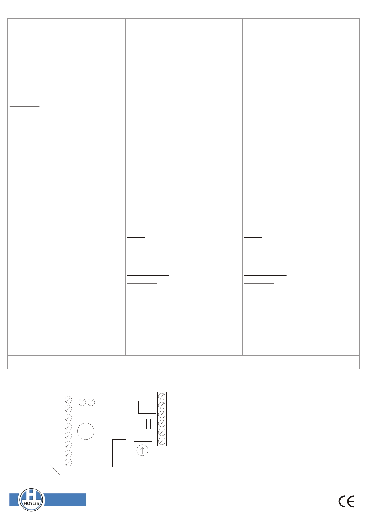
The trigger terminals, A is a -ve applied to trigger, B is +ve applied to trigger.
12V DC
-VE TRIGGER
+VE TRIGGER
Function
Controls
Timing
Range
Relay
Control
R
+ - A B C D
LED
T1
T2
MIN
T
NO NO
NC NCCOM COM
MAX
Note
This unit requires 12v dc to power it at all times. (10-14v dc).
Note 1
RELAY 1 RELAY 2
If the input is not removed when the timing has finished in
both momentary trigger modes, then the led will remain
illuminated red and the relay will remain in the state that it
was when the led illuminated red until the trigger is removed.
Contact ratings
The relay is DPCO rated 1Amp @ 12v dc. It must not be
used to switch mains voltages.
Hoyles Electronic Developments Ltd
T. 01744 886600 F. 01744 886607 E. sales@hoyles.com W. www.hoyles.com
60043 Iss 5 May 07
 Loading...