

Installation and operating instruction
ABRA 6

CONTENT
INTRODUCTION
Page 3
DESCRIPTION OF THE DEVICE
Electronical control unit Page 4
Display Page 5
Door sensor Page 5
Air inlet flap Page 5
Hightemperature sensor Page 5
Power source adapter Page 5
INSTALL ATION
Door sensor intallation Page 6
Hightemperature sensor installation Page 6
Air inlet flap installation Page 7
Electronical unit connection Page 7
SETTINGS
Setting of device and communication channel Page 8
Setting for UNI-product Page 9
OPERATING
Informations on display Page 10
Alarms and warnings Page 11
Power source shortage Page 11
TROUBLESHOOTING Page 12
LIST OF PRODUCTS Page 13
WARRANTY Page 14
2

We would like to thank you for purchasing electronical fireburning
control ABRA 6.
Based on the temperature in the burning chamber this fireburning
control optimizes combustion by precise dosage of inlet air.
The installation of this product must be carried out by specialist
– stove maker – only.
Before you start using the device we would like to invite you to read
this manual and follow the instruction inside.
INTRODUCTION
3
RUN
SET
S1
TK
T1
12V DC
PWR
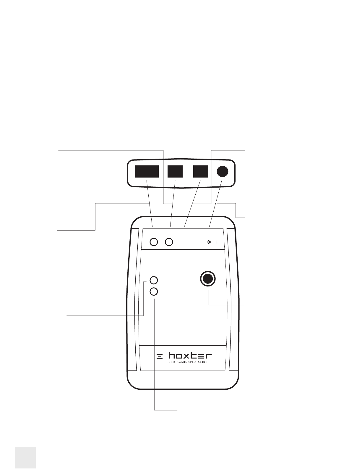
ELECTRONICAL FIREBURNING CONTROL UNIT
• Power source adapter 12V
• Electronical unit includes 9V backup battery
• Heat resistance max 40°C / 104°F
Description of inputs and control diode
S1
• Connector input
for air inlet flap
• Control diode signals
when flap is changing
its position
RUN
• Operation
control diode
• Flashing signals
ongoing burning
process
• If switches off
during set-up
process, it confirms
the current step
TK
• Connector input
for door sensor
• Control diode signals
closed position
of the door
T1
• Connector input
for hightemperature
sensor
12V DC
• Connector input
for power supply
adapter
DESCRIPTION OF THE DEVICE
SET
• Functional button
used for set-up
• Browse through
choices by short
pressing
• Confirm choice
by holding (5 sec)
PWR
• Control diode signals
power supply 12V
4
DIS PLAY
• Display shows information from
the control unit through FM waves
• Power supply – 3pcs of 1,5V AAA battery
• Heat resistence - max 40°C / 104°F
• Signal range between electronical control
unit and display max 50m / 164 ft.
• (more instruction for display unit in chapter
„OPERATION“ on page 10)
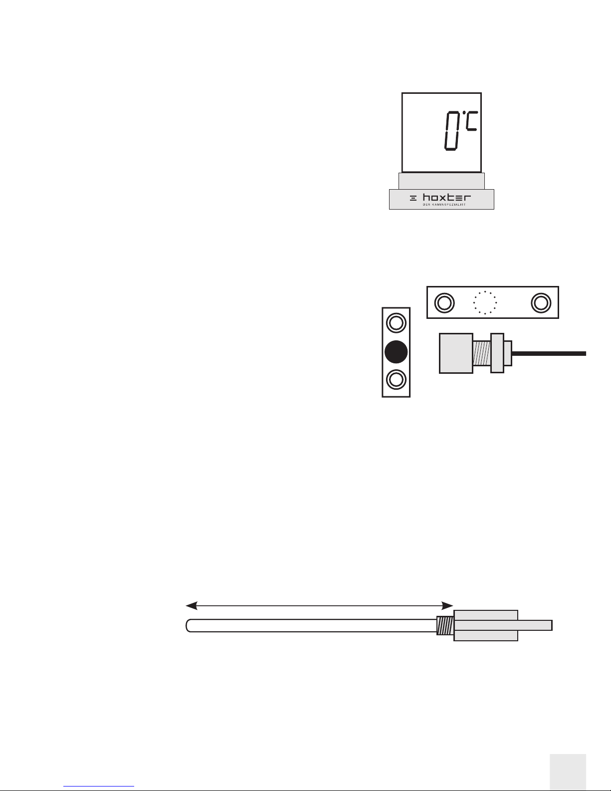
DOOR SENSOR
• Sensor with connecting cable, lenght 4 m / 13 ft.,
heat resistence of the cable 180°C / 356°F (A)
• Magnetic counterpart (B)
• Steel hitch (only compatible
with HOXTER products) (C)
AIR INLET FLAP
• Heat resistence of the stainless steel flap and its components max 50 °C / 122 °F
• Lenght of the cable 4m / 13 ft., heat resistence of the cable 180 °C / 356 °F
HIGHTEMPERATURE SENSOR
• Range 0°C - 1200°C / 32°F - 2192°F
• Heat resistence of the hightemperature sensor and ceramical cover max 1200 °C / 2192°F
• Heat resistence of the cable 400 °C / 752°F, lenght of the cable 5 m / 16,4 ft.
• Assembly lenght of the sensor is adjustable 140-160mm / 5.5 – 6.3 In.
POWER SUPPLY ADAPTER
• Input 110-230V
• Output 12V DC
• Heat resistance max 40 °C / 104 °F, lenght of the cable 2 m / 6.5 ft
140 - 160 mm
5
A
B
C

DOOR SENSOR INSTALLATION
Break out the indicated opening in the steel
hitch (B), pull the door sensor through this hole
(A) and fasten with the distance barrel (C)
and a nut (D).
Fasten the steel hitch with the door sensor
on designed place at the frame (E).
Enclose the magnetic counterpart on the
bottom edge of the doors.
Both the door sensor and the magnetic
counterpart must be placed in the common
axis. The distance between those parts
must be 2-12mm / 0.08-0.47 in. (F) In case
the distance between these part is too big,
underlay the magnetic counterpart with the
distance barrel.
The magnetic counterpart is strong enough
to held on place. For the fixation use
enclosed screws (G).
A
B
C
D
E
INSTALLATION
1
2
3
4
5
2-12 mm
F
6
G

HIGHTEMPERATURE SENSOR INSTALLATION
Screw the hightemperature sensor on fireplace
insert or stove doors to the designed place.
Minimal lenght for correct measurment
is 20mm / 0.8 in at its end (H).
AIR INLET FLAP INSTALLATION
Connect the air inlet flap by alu pipe with the fireplace insert or stove doors.
The connection between the air inlet flap and the product must be tight enough.
When installing into closed-in build, the air inlet flap must be placed
outside the hightemperature place. The heat resistence of the air inlet
flap is max 50°C / 122°C.
CONTROL UNIT CONNECTION
Connect all the components and power supply adapter with the control unit.
After that plug the power supply adapter to the power feed.
For complete instruction
how to set-up the control
unit follow the instruction
stated in the chapter
„SET-UP“
RUN SET
S1 TK T1 12V DC
PWR
1
1
1
2
2
2
min.
20 mm
H
7

SETTING UP THE PRODUCT AND COMMUNICATING CHANNEL
There is a red control diode RUN flashing.
Press the SET button on the control unit until the red control diode turns off.
Remove the strip between the battery and the contact in the display. It prevents
the batteries to power the display. In case, the display is already powered,
remove and after short moment put back inside all the batteries.
The first number from the product codes appears on the
display (list of product codes on page 13).
Scroll to the required number by short presses of the SET
button. To confirm the selection hold the SET button for 5 sec.
Now the last two numbers from the product codes are active. Scroll to the
required number by short presses of the SET button. To confirm the selection
hold the SET button for 5 sec.
Now the number of the communicating channel is active.
Confirm by holding the SET button. In case there is another
fireburning control installed or another source interfering the
communication, repeat the SET-UP process and choose
different channel.
Set message appears on the display to confirm the set-up
proces was finished succesfully. After a while the fireburning
control turns itself into operating mode.
SET-UP
SHORT PRESS TO CHANGE VALUE.
HOLD TO CONFIRM THE CHOICE.
1
2
3
4
5
6
7
8
RUN SET
S1 TK T1 12V DC
PWR
8

UNI PRODUCTS SETTING
This settings is defined for individual fireplaces or to adjust the time of active
burning out phase. UNI setting is available in three different options for
starting temperatures (T
start
) - pro 80°C, 250°C or 400°C. The choice for the
correct starting temperature depends on the place where the hightemperature
sensor is installed – in burning chamber, or in the accumulating system.
When setting the UNI system, follow the step 1-5 as in the chapter
„Setting up the product and communicating channel“.
After confirmation of the UNI product code, the option for temperature T5
appears on the display. When this temperature is reached, the air inlet flap
is closing completely, the phase of active burning ends and phase of hot
coal is starting. By default the temperature T5 is set on the 65% value of the
temperature T4.
For adjusting applies:
Values higher than 65% shortens the phase of active burning
Values lower than 65% extends the phase of active burning
To confirm the choice hold the SET button. After that continue with the
option for communicating channel.
St1
T
3
T
4
T
5
T
start
T
max
St2
St3 St4
St5
time
temperature
1
2
3
COMBUSTION CURVE
9

Stage or phase of the burning
Because of different conditions of each burning (humidity, firewood quantity,
thrust of the chimney) the fireburning control unit ABRA 6 doesn’t control the
combustion by fixed time intervals for each phase. The period and process of
the combustion are always derived from maximal reached temperature (T
ma x
)
in the second phase of burning.
INFORMATIONS ON DISPLAY
Informations on the display are beeing updated
each 8 second. For instant update or to activate
the backlight push the display in the upper part.
During common operation the display
shows four basic values:
Current temperature in the burning chambre
Temperature measured by the hightemperature sensor
Time of burning
The period starts when the doors sensor contact
is interrupted (opened doors) and ends when the
combustion stops . The fireburning control is now
in phase 0, the hightemperature sensor measures
temperature lower than 50°C.
Strenght of signal
The marks in the lower part of the display are showing
the strenght of the signal between the display and the
electronical control unit. It shows seven marks when
the signal is full, when the signal is too weak,
the display shows SIG warning message.
OPERATING
St1
T
start
T
max
St2 St3 St4 St5
time
temperature
10

ALARMS AND WARNING MESSAGES
SiG warning message - the signal strenght beween display
and control unit is too weak.
bAt warning message - the voltage of the batteries in the
display is too low. Replace the batteries.
Alarm - Alarm is signaled by beeps and flashing of the display.
AL-1 Power supply of the electronical control unit failure. For security reason the
backup battery allows to open the air inlet flap and the fireburning controls turns
itself off. Check the power supply feed.
AL-2 Power supply of the electronical control unit failure
and also weak backup battery in the electronical control unit.
Replace the backup battery in the electronical control unit
and check the power supply feed.
AL-3 Bad heating. All of following conditions occured. The time period of the first
burning phase was longer than 30min, the temperature in the burning chamber
didn’t reach 90°C and decreased of more than 10°C. The fireburning control
automatically ends the combustion proces and when the temperature drops bellow
50°C it closes the air inlet flap.
St1 - first phase. This stage begins with opening and closing of the doors and
ends when the starting temperature
tstart
is reached. Starting temperature is
determined with the choice of product during the set-up process.
St2 - second phase. Second phase starts after the temperature
tstart
is reached
and continues for at least 15 min. During this stage the maximal temperature
tmax
is reached.
St3 - third phase is the stage of active burning.
St4 - fourth phase is the stage of active burning out, the air inlet flap lets in only
minimal possible air required for combustion.
St5 - fifth phase is the stage of hot coals, the air inlet flap is closed completelly.
St0 phase zero - non-active phase, when the temperature in the burning chamber
is lower than 50°C. Fireburning control automatically wents in saving mode.
11

Failure Cause Solution
Control diode RUN
doesn’t flash.
Electronical fireburning
control unit is in set-up
mode.
Remove and put back
batteries from the
display. Finish the set-up
process.
Sig is showing on the
display, control diode
PWR is off.
Electronical fireburning
control unit is not feeded
from the power supply
feed.
Check the connection
between electronical
fireburning control unit
and the power supply
feed.
Display is showing SiG,
control diode PWR is
on, control diode RUN is
not flashing.
Electronical fireburning
control unit is in set-up
mode.
Remove and put back
batteries from the
display. Finish the set-up
process.
Display is showing SIG,
control diode PWR
is on, control diode
RUN is flashing.
Display is out of reach
from the electronical
fireburning control unit.
Put the display closer
to the electronical
fireburning control unit.
Display and electronical
fireburning control unit
are not on the same
channel.
Repeat the whole proces
described in chapter
„Setting up the product
and communicating
channel“.
The communication
between display and
electronical unit is
interfered.
Repeat the whole proces
described in chapter „
Setting up the product
and communicating
channel“. Change the
communication channel
as described in point
7 of this chapter.
TROUBLESHOOTING
12

HOXTER
1.01 HAKA 37/50
1.02 HAKA 63/51
1.03 HAKA 67/51h
1.04 HAKA 89/45h
1.05 ECKA 67/45/51h
1.06 ECKA 90/40/40h
1.07 HAKA 37/50W
1.08 HAKA 63/51W
1.09 HAKA 63/51WT
1.10 HAKA 67/38W
1.11 HAKA 67/51W
1.12 HAKA 89/45Wh
1.13 ECKA 67/45/51Wh
UNIVERSAL
2.01 UNI - 80°C
2.02 UNI - 250°C
2.03 UNI - 400°C
LIST OF PRODUCTS
13

14
Warranty for the electronical fireburning control ABRA 6 and its componenst is
24 months. The warranty doesn’t apply on mechanical damage. The warranty
also doesn’t apply if the damaged products were exposed to temperatures
higher than the defined maximal values.
Installation of the electronical fireburning control ABRA 6 must be done by
specialist – stove maker. For warranty and post-warranty service contact
please the company that installed the product.
Date of the installation:
Company / Stove maker:
Address:
Phone:
WARRANTY

NOTES
15

HOXTER gmbh
Kirchgasse 1
91217 Hersbruck
Germany
Tel.: +49 (0)9151 8659 163
info@hoxter.de
www.hoxter.de
HOXTER a.s.
Mlýnská 326/13
602 00 Brno
Czech republic
Tel.: +420 518 777 701
info@hoxter.eu
www.hoxter.eu
 Loading...