

Howe 100-RLA Installation Manual
Rapid Freeze ICE FLAKERS
INSTALLATION & SERVICE MANUAL
and parts catalog
Selective Purpose Flake Ice Machines
2,000 – 40,000-lb/day capacity
Flooded Ammonia series (RLA)
Recirculated Ammonia series (RLR)
TECHNICAL ASSISTANCE LINE
Howe Corporation
1650 North Elston Avenue
Chicago, IL 60622
1-773-235-0200
www.howecorp.com
e-mail: howeinfo@howecorp.com

Notice
This manual and all information contained herein are provided “as is” and are subject to change
without notice. Howe Corporation makes no warranty of any kind with regard to this
manual, including, but not limited to, the implied warranties of merchantability and fitness
for a particular purpose. Howe Corporation shall not be liable for any errors or for incidental
or consequential damages in connection with the furnishing, performance, or use of this manual.
The information contained herein is applicable to the specified models current at the time of
publication. Some information in this manual will be of use to owners of older model machines.
The reader is cautioned that use of this manual with older equipment is at the user’s risk. Howe
Corporation makes no warranty or guarantee, explicit or implicit with regard to the use of this
manual with equipment models outside the scope of this manual. If in doubt of the scope of this
manual, contact Howe Corporation.
© Howe Corporation 2005. All rights reserved. Reproduction, adaptation, or translation of this
manual is prohibited without prior written permission of Howe Corporation, except as allowed
under the copyright laws.
Howe Corporation
1650 North Elston Avenue
Chicago, IL 60622
Phone: (773) 235-0200
Fax: (773) 235-0269
e-mail: howeinfo@howecorp.com
web: www.howecorp.com
Revision date: April, 2012
- ii -

TABLE OF CONTENTS
2. Introduction ................................................................................................................................ 1
Introduction to the Rapid Freeze® Ice Flaker ................................................................................. 2
Important Safety Information ...................................................................................................... 4
Safety Symbols and What They Mean ........................................................................................ 4
3. Receiving and Inspection of Equipment ................................................................................... 5
4. Installation of the Rapid Freeze Flaker .................................................................................... 7
Installation Conditions ................................................................................................................ 8
Installation without ice bin .......................................................................................................... 8
Installation on Ice Storage Bins .................................................................................................. 9
Recommended Installation Method on Ice Bin ........................................................................... 9
Water Supply & Filter Connections .......................................................................................... 10
Wiring & Electrical Connections .............................................................................................. 13
Piping Connections ................................................................................................................... 13
5. Accessories ................................................................................................................................ 16
Electric Eye Ice Level Control .................................................................................................. 16
Installation Instructions for Photoeye Ice Level Controls ......................................................... 16
Ice Bin Thermostats .................................................................................................................. 17
Rib Heating Elements ............................................................................................................... 17
6. Start & Adjust .......................................................................................................................... 19
Checklist.................................................................................................................................... 20
7. Electrical Systems ..................................................................................................................... 23
Control Panel Layout ................................................................................................................ 24
Control Module ......................................................................................................................... 28
8. Maintenance .............................................................................................................................. 29
Ice Machine Cleaning Instructions ............................................................................................ 30
9. Troubleshooting ........................................................................................................................ 35
Operation ................................................................................................................................... 36
Freezing and Refrigeration ........................................................................................................ 37
Ice Storage and Removal .......................................................................................................... 39
Speed Reducer ........................................................................................................................... 40
10. Service & Adjustment ............................................................................................................ 41
Replacement of Photoeye Ice Level Controls ........................................................................... 43
Replacement and Adjustment of Ice Deflector ......................................................................... 43
Replacement and Adjustment of the Ice Deflector Scraper ...................................................... 44
Replacement and Adjustment Of The Squeegee & Squeegee Wrapper ................................... 44
- iii -

Replacement Of Water Pump .................................................................................................... 45
Replacement Of Drive Motor.................................................................................................... 45
Replacement Of Speed Reducer and Flexible Coupling ........................................................... 46
Replacement and Adjustment Of Water Float Valve ................................................................ 47
Replacement of Solenoid Valve ................................................................................................ 48
Replacement and Adjustment of the Hand Expansion Valve (TXV) ....................................... 48
Replacement and Adjustment of Ice Blade ............................................................................... 49
Bearing Replacement ................................................................................................................ 49
11. Appendix A Ice Flaker Drawings .......................................................................................... 53
12. Appendix B Wiring Diagrams ............................................................................................... 63
13. Appendix C Parts List ............................................................................................................ 69
- iv -

2.Introduction
2. Introduction
- 1 -

2.Introduction
The Rapid Freeze by Howe ice flaker is backed by over 50 years of proven performance and
innovation. Long known for durability and reliability, our flake ice equipment is unsurpassed in
energy efficiency and low maintenance.
Available in a wide variety of sizes and configurations, the rugged Rapid Freeze flaker can be
found in diverse applications from supermarkets and food processors to remote fishing villages.
®
Introduction to the Rapid Freeze
Refer to Figure 1 for a guide to the major components of the Howe ice flaker. Among the key
features are:
Evaporator: The heart of the Howe ice flaker is the carbon steel, flooded evaporator. The
carbon steel construction provides exceptional heat transfer properties, while the hard
chrome lining provides a clean, sanitary, corrosion-resistant freezing surface.
Ice Blade: An investment-cast stainless steel ice blade removes the ice from the freezing
surface. The material and method of fabrication mean that the blade will never need resharpening.
Squeegee: Made of USDA-approved material, the squeegee removes excess water from
the surface of the ice, guaranteeing that the ice produced by the flaker is dry and subcooled.
Ice Flaker
Ice Deflector: Mounted underneath the ice blade, the deflector directs the harvested ice
toward the center of the drop zone.
Water Distribution Pan: The water distribution pan and tubes provide a continuous flow
of water over the evaporator surface. Ice production is rapid and continuous, with no
interruption in production.
Water Sump: Collects water that was not frozen on the evaporator, and re-circulates it to
the water distribution pan. The incoming water supply is connected here, through a float
valve that maintains a constant water level in the sump.
Bearings: Oversized bronze bearings ensure a long service life.
Control Panel: The “brains” of the ice flaker, the control panel governs all of the
functions of the ice flaker. Available in a NEMA4 weatherproof enclosure for harsh
environments or frequent washdown applications.
Drive Motor: Open, drip-proof drive motor. Totally enclosed, fan-cooled motor available
for harsh environments or frequent washdown applications.
- 2 -

2.Introduction
n
h
Figure 1
Howe Rapid Freeze
®
Ice Flaker
Major Components
Speed Reducer
Water
Distribution Pa
Main Shaft
Evaporator
Drive Motor
Squeegee
Ice Blade
Water Regulating
Valve
Water Pump
Water Return
Troug
Bearing
(Bottom)
Ice Deflector
Water Sump
- 3 -

2.Introduction
Important Safety Information
The information found in this manual is intended for use by individuals possessing adequate
backgrounds of electrical, refrigeration and mechanical experience. Any attempt to repair or
make alterations to this equipment may result in personal injury or property damage. The
manufacturer or seller cannot be responsible for the interpretation of this information, nor can it
assume any liability in connection with its use.
Safety Symbols and What They Mean
Please read and understand this manual prior to installing or operating this Rapid Freeze ice
flaker. You must be completely familiar with the start-up, operation and service of this flaker
before you attempt to start, operate or adjust this piece of equipment.
The following safety symbols will alert you to any special precautions throughout this manual:
***DANGER***
BEWARE OF HAZARDS THAT CAN RESULT IN PERSONAL INJURY
***DANGER***
***WARNING***
“DO IT RIGHT” OR RISK SEVERE PERSONAL INJURY.
FOLLOW INSTRUCTIONS CAREFULLY
***WARNING***
***CAUTION***
RISK OF PERSONAL INJURY OR DAMAGE TO EQUIPMENT
FOLLOW INSTRUCTIONS CAREFULLY
***CAUTION***
- 4 -

3.Receiving and Inspection of Equipment
3. Receiving and Inspection
of Equipment
- 5 -

3.Receiving and Inspection of Equipment
Upon receipt of your Rapid Freeze ice flaker, you should first inspect the carton very carefully, to
determine if any damage might have occurred during shipment. If you suspect any damage has
occurred, it should be noted immediately on the freight bill. In addition, a written notice must be
sent to the agent representing the freight carrier. The written notice should request an inspection
by the agent to verify damage during shipment. If the damage was noticed after un-crating of the
carton, it is necessary to keep the original shipping container so that the carrier’s agent can
investigate the damage claim thoroughly.
If a repair is necessary for the Rapid Freeze machine, you must first obtain written permission
from the factory before beginning any repairs. Unauthorized work on your Rapid Freeze ice
flaker could result in voiding the machine’s warranty.
Immediately upon receipt of equipment, before placement or installation of
equipment, verify the electrical, and refrigerant configuration are correct as
ordered. If any discrepancies are found, notify Howe Corporation immediately
prior to any installation.
- 6 -

4.Accessories
4. Installation of the Rapid
Freeze Flaker
- 7 -

4.Accessories
Installation Conditions
Rapid Freeze Ice Flakers are designed to operate in ambient temperatures warmer than 50°F. Do
not install ice flaker(s) in refrigerated cold rooms or in areas where the ambient temperature is
lower than 50°F (10°C). If it is unavoidable, ice flakers may be installed in areas down to 45°F
(7°C) provided that three (3) electric rib heaters (available from the factory) are installed to heat
the bottom casting to prevent ice buildup on the three supporting ribs for the bottom bearing. If
installed in cold ambient conditions, it is advisable to supply the ice flaker with warmer water
through a water mixing valve, around 60°F (15°C).
When a combination of cold water and cold air temperature exists, the mixing valve and rib
heaters must be used. Failure to do so will cause the lower water collecting trough and
sump to plug up with ice to the extent that the water may overflow into the ice storage bin
in addition to blocking the water inlet to the pump. Also, it is advisable to direct air blowers
and fans away from the ice flaker, as air velocity over the ice flaker will reduce the effectiveness
of the heaters.
***CAUTION***
NEVER INSTALL AN ICE FLAKER IN A COLD ROOM 45°F (7°C) OR LOWER. THE
ICE FLAKER WARRANTY IS VOID IF THE ICE FLAKER IS INSTALLED IN A COLD
ROOM, OR OUTSIDE WHERE THE AMBIENT TEMPERATURE MAY DROP BELOW
FREEZING.
***CAUTION***
Optimum surrounding air temperature range 60°F (15°C) to 95°F (35°C)
Minimum air temperature (without heater) 50°F (10°C)
Minimum air temperature (with heater) 45°F (7°C)
Maximum air temperature 100°F (38°C)
Optimum water temperature range 60°F (15°C) to 80°F (25°C)
Minimum water temperature (without water mixing valve) 45°F (7°C)
Minimum water temperature (water mixing valve must be used) 36°F (2°C)
Maximum water temperature 90°F (32°C)
Installation without ice bin
Rapid Freeze Ice Flakers may be installed under certain conditions without a typical ice bin.
When the flaker is installed without a bin, it must have a drainable condensate pan located under
the machine. The flaker must also be mounted high enough off the floor so there is no chance
that somebody may reach into the evaporator from below either with a pole, or their arm, while
the flaker is operating.
Refrigerating the ice storage bin is not normally necessary nor is it recommended. However, in
those cases where ice is to be discharged into an existing freezer room then, as a minimum,
electric heaters should be installed on the bottom casting and the sump regardless of the actual
ambient temperature of the air surrounding the ice flaker. Air from the freezer room should be
directed away from the ice flaker opening otherwise, the effectiveness of the heaters will be
reduced. If the storage area is held at 28°F (-8°C) or colder, it is advisable to install the ice
flaker 1 to 2 feet above the freezer and use a duct section to direct the ice into the storage bin.
- 8 -

Installation on Ice Storage Bins
4.Accessories
Rapid Freeze
usually mounted directly on top of an insulated ice storage bin. The storage bin must have an
insulated top, with a drip pan that is an integral part of the top designed specifically for the
Rapid Freeze Ice Flaker model installed on it. The ice bin should be designed to support the
weight of the flaker, and the ice stored inside the bin. Most ice storage bins can handle the
weight of a 2000, 3000, 4000 or 6000 pound capacity ice flaker without any additional bracing.
It is recommended that the bin manufacturer be consulted before any ice flaker is placed on
top of a bin. The weight of each ice flaker machine, along with the diameter of the hole required
for ice entry into the bin, is given on the specification sheet for that particular model.
Allow for a MINIMUM OF 6" clearance on top of the ice flaker for removal of the speed
reducer, and sufficient space around the unit (approximately 3 feet) for inspection and service.
Recommended Installation Method on Ice Bin
Refer to bin manufacturer’s installation instructions for proper assembly and set up procedures.
Locate and set the bin on a solid level footing. Once the bin is set in place and leveled, the
Rapid Freeze ice flaker can be placed inside the drip pan.
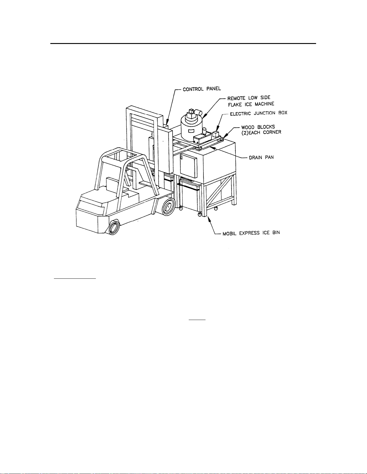
Exhibit 2 illustrates the forklift and block method of placing the ice flaker on the bin.
Forklift & Block Method
You will need:
®
Ice Flakers are designed to run smoothly and without vibration. The machines are
Forklift truck with adequate load and height capacities
(8) 2 X 4 wood blocks approximately 6-8" long
(2) 2 X 4 's approximately 36" long
Pry Bars
Step 1. Position ice flaker on forks.
Step 2. Stack two wood blocks in each corner of the drip pan on the ice bin.
Step 3. Lift ice flaker over the wood blocks, position ice drop zone over the bin top
opening, then set the flaker on the blocks.
Step 4. Remove forklift.
Step 5. Stack the two 36" long 2 X 4's on the side of the bin beside the drip pan,
overlapping the front and back of the bin.
Step 6. Using a pry bar as a lever on the 2 X 4's raise the side of the flaker and remove
the TOP blocks only.
Step 7. Repeat steps 5 & 6 on the other side.
Step 8. With the flaker sitting on one (1) block under each corner, repeat steps 5, 6 & 7
removing the remaining blocks. Drip pan flanges MAY bend slightly.
Step 9. Straighten the drip pan flanges (if necessary)
- 9 -
4.Accessories
Figure 2
Ice Flaker Installation
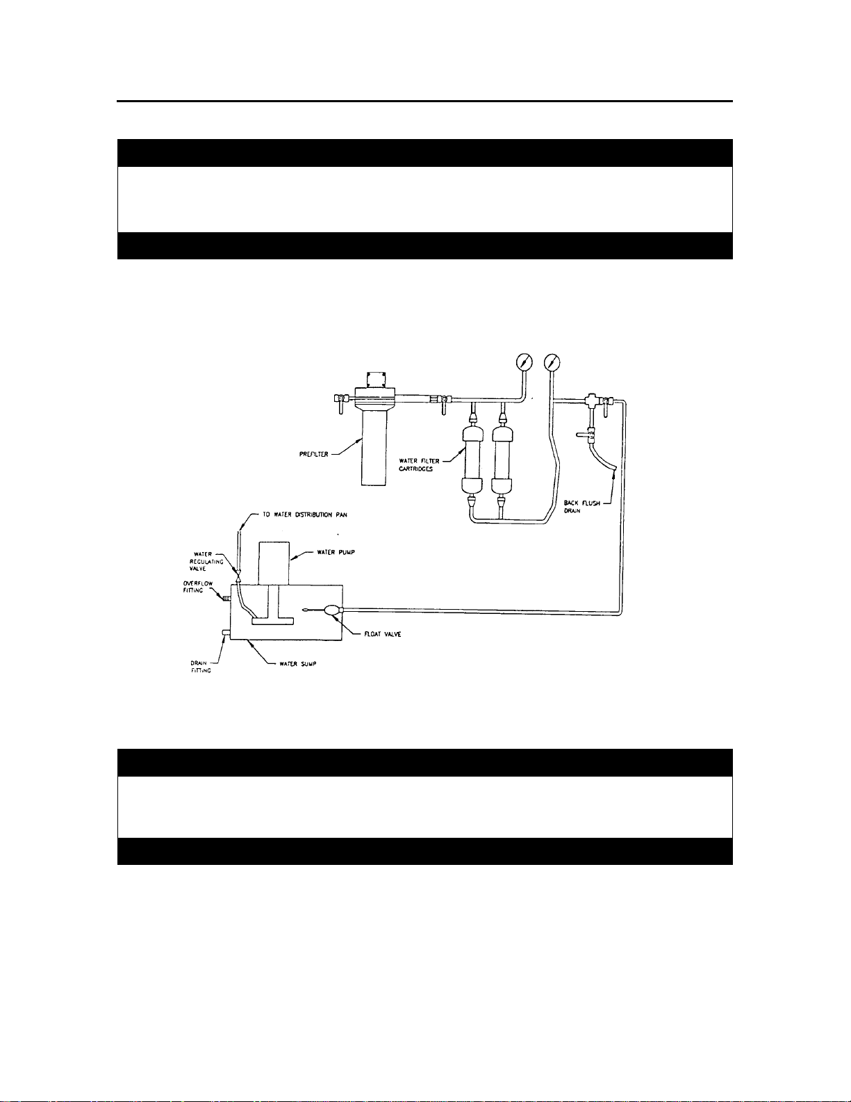
Water Supply & Filter Connections
WATER LINE: Connect a 1/2" galvanized or 1/2" ODS COPPER water pipe from the closest
convenient water line to within 2 to 4 feet of the ice flaker water sump. Install a water line
shutoff valve near the ice flaker. Use copper tubing between water valve & water inlet
connection located on water sump.
Refer to the engineering sheet for the line size connection from the ice flaker sump to the water
supply line. If water supply has silt or sand in it, a coarse water filter is recommended.
- 10 -
4.Accessories
***CAUTION***
MINIMUM WATER PRESSURE OF 30 PSIG IS REQUIRED AT THE ICE FLAKER
FOAT VALVE TO INSURE ADEQUATE WATER FLOW.
MAXIMUM ALLLOWABLE WATER PRESSURE TO THE FLOAT VALVE IS 60 PSIG.
***CAUTION***
Figure 3
Water Supply & Filter Connections
***WARNING***
NEVER OPEN CHARGING VALVE, ALLOWING REFRIGERANT TO VENT
DIRECTLY TO THE ATMOSPHERE. REFRIGERANT MUST BE REC LAIMED
THROUGH A RECOVERY SYSTEM.
***WARNING***
- 11 -

4.Accessories
***CAUTION***
SERVICE/INSTALLATION PERSONNEL MUST HAVE KNOWLEDGE OF
REFRIGERATION SYSTEMS TO PROPERLY CHARGE THIS FLAKER.
***CAUTION***
***WARNING***
ALL RAPID FREEZE REMOTE MODEL ICE FLAKERS ARE SHIPPED WITH A
SMALL HOLDING CHARGE OF DRY NITROGEN.
SYSTEM MUST BE EVACUATED PRIOR TO CONNECTING TO THE AMMONIA
SYSTEM.
***WARNING***
Follow good accepted practice and procedure to charge refrigerant into the system briefly
outlined as follows.
1) Pressurize and test the system checking for leaks.
2) Use a good quality vacuum pump to evacuate the system. Make sure all shut-off
valves are OPEN so that the entire system is evacuated. Allow vacuum pump to run
for several hours.
3) Break vacuum with refrigerant and evacuate again.
4) Repeat step 3. This is called "triple evacuation". It ensures that all air and moisture
has been removed from the system. Failure to do so may result in compressor
burnout.
- 12 -

4.Accessories
Wiring & Electrical Connections
***CAUTION***
ELECTRICAL WIRING SHOULD BE PERFORMED BY QUALIFIED TECHNICIANS
FOLLOWING LOCAL ELECTRICAL CODES.
***CAUTION***
The electrical control panel is supplied with remote low side (-RLA or RLR) machines, but is
shipped loose to be mounted on the wall (near the bin) for easy access to controls. To install
control panel:
1) Install disconnect (not supplied by factory), and connect main power to terminals marked
L1 and L2 in the ice flaker control panel.
2) Install optional on-off switch to the two terminals designated "On-Off switch". Remove
wire jumper on these terminals if you are installing a remote switch.
3) A jumper is installed between terminal marked “Line A” and terminal marked "Line B".
This will enable the liquid line solenoid on the ice flaker to operate properly.
4) Following local applicable electric codes, wire the remote panel to the components (drive
motor, water pump, and solenoid valve) on the flaker. The drive motor and water pump
should be wired to terminals T
solenoid valve, and dual pressure regulator are wired to terminals marked, “solenoid
valve” in the flaker control panel.
5) If the flaker has factory installed/supplied photo eye ice level controls, connect the long
cables from the ice flaker to the relay base (or terminal strip) in the control panel. The
wires are color-coded and must be connected to the proper terminals. The BLUE leads
from both the emitter and receiver cables connect to terminal # 10 (Blue terminal), the
BLACK lead from the receiver only, connects to terminal # 11 (Black Terminal), and the
BROWN leads from both the emitter & receiver connect to terminal # 1 (Brown
Terminal). Refer to Figure 15 on page 67 for electric eye wiring diagram.
THE SENSOR LEADS FOR THE ICE LEVEL CONTROLS MUST NOT BE RUN IN
THE SAME CONDUIT AS THE MOTOR AND SOLENOID WIRES. SENSOR WIRES
MUST BE RUN IN SEPARATE CONDUIT.
Piping Connections
When installing the ice flaker, it is important that the flaker is properly piped as indicated below.
When connecting to a AMMONIA refrigeration system, a dual pressure regulator valve must also
be provided and installed on the suction line to regulate the evaporator suction temperature to
between –5°F and -10°F (-20.4°C to -23.2°C).
and T3 respectively, in the control panel. The
1, T2,
***WARNING***
***WARNING***
- 13 -
4.Accessories
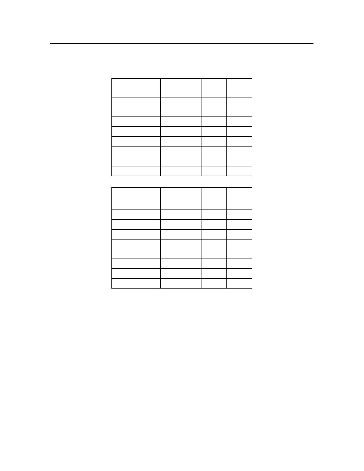
Table 1
Flooded Ammonia Piping Connection Sizes
Approximate
MODEL
Ammonia
Charge (lbs.)
2000-RLA 15 ½” 1”
3000-RLA 18 ½” 1”
4000-RLA 22 ½” 1 ¼"
6000-RLA 35 ½” 1 ¼"
50-RLA 130 ½” 1 ½”
75-RLA 190 ½” 2”
100-RLA 240 ½” 2”
200-RLA
Re-Circulated Ammonia Piping Connection sizes
Approximate
MODEL
Ammonia
Charge (lbs.)
2000-RLR 8 ½” 1”
3000-RLR 12 ½” 1”
4000-RLR 15 ½” 1 ¼"
6000-RLR 22 ¾” 1 ½"
50-RLR 75 ¾” 2”
75-RLR 125 ¾” 2”
100-RLR 150 1” 2 ½”
200-RLR 280 1” 3”
Liquid
Liquid
Suction
Suction
The ice flaker as, supplied by Howe Corporation, was thoroughly cleaned and dehydrated at the
factory. Foreign matter may enter the system by way of the field piping. Therefore, care must
be used during installation of the piping to prevent entrance of foreign matter.
Install all refrigeration system components in accordance with applicable local and national
codes in conformance with good practice required for the proper operation of the system.
The following procedures should be followed:
a. Do not leave dehydrated equipment or lines open to atmosphere any longer that is
absolutely necessary.
b. Suction lines should be sloped ¼” per 10 feet towards the compressor.
c. Pipes sized for normal runs (up to 100 FT)
d. Avoid excessive number of elbows/bends in all refrigerant lines, especially suction lines.
e. Use SCH 80 steel pipe for all ammonia lines except suction lines 1-1/4” and larger may
be SCH 40.
- 14 -
4.Accessories
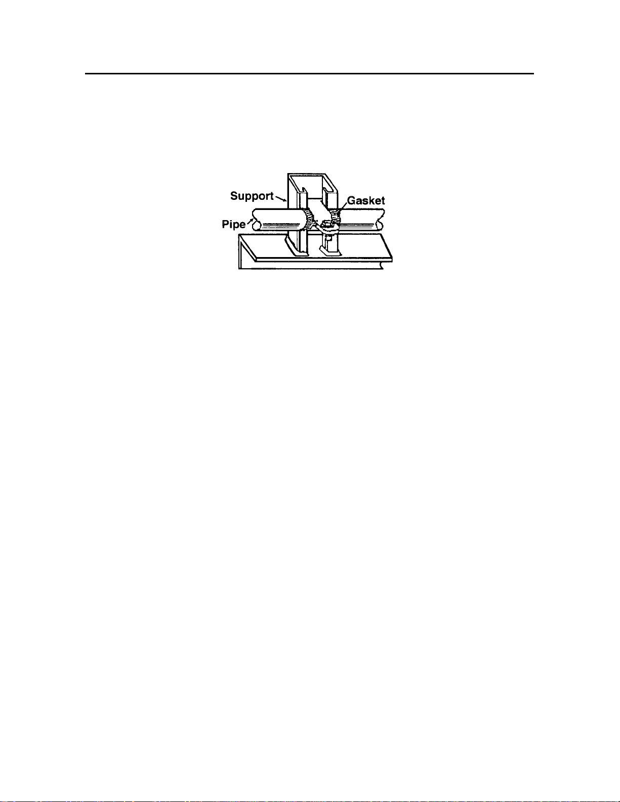
Figure 4
Refrigerant Piping Support
1. Ensure that refrigerant lines are supported and fastened properly. See Figure 4 for an
example.
2. When changing directions in a run of tubing, no corner should be left unsupported.
Supports should be placed a maximum of 2 feet in each direction from the corner.
3. Do not use short radius ells. Short radius elbows have points of excessive stress
concentration and are subject to breakage at these points.
4. Thoroughly inspect all piping after the equipment is in operation and add supports
wherever line vibration is significant. Extra supports are relatively inexpensive as
compared to refrigerant loss.
Line Insulation
After the final leak test, refrigerant lines should be insulated to reduce heat pick-up and prevent
the formation of flash gas in the liquid lines. Suction lines should insulated with ¾” wall
Armstrong “Armaflex” or equal. Liquid lines should be insulated with ½” wall insulation or
better. Insulation located in outdoor environments should be protected from UV exposure to
prevent deterioration of the insulation.
- 15 -

4.Accessories
4. Accessories
Electric Eye Ice Level Control
The use of a suitable ice level control to shut off the ice flaker when the storage bin fills is
mandatory. Failure to use the proper ice level control will cause the ice to build within the ice
flaker evaporator after the bin is full to capacity. Operating the flaker with a full bin will cause
the ice deflector to bend or break as it “churns” the ice. In extreme cases it may result in damage
to the speed reducer and/or the electric drive motor and flexible coupling.
The proper and approved bin level control is the photoelectric eye. When ordered with the
machine, the eyes are mounted on brackets that will attach to the bin top or wall. The cables are
routed through the bottom casting of the ice flaker. The power module is mounted inside the ice
flaker control panel.
Figure 5
Electric Eye Ice Level Control
Installation Instructions for Photoeye Ice Level Controls
1) Turn off the ice flaker at the control panel and at the main shut-off disconnect. Cover or
remove any ice that may be present in the ice storage bin.
2) Open the front cover of the flaker control panel. Locate the 11-pin mounting base for the
photoeye control module. If the control module is installed in the base, unplug the control
module.
3) Mount the photoeye emitter. If the storage bin top was supplied by Howe, there will be
recessed pockets in the bin top for placement of the photoeye elements. If pockets are not
present, mount the emitter securely to the top or side wall of the bin, and align the emitter so
that it projects its beam directly across the ice drop opening.
4) Locate the photoeye receiver. Again, if the storage bin top was supplied by Howe, there will
be recessed pockets in the bin top for placement of the photoeye elements. If pockets are not
- 16 -

4.Accessories
present, mount the emitter securely to the top or side wall of the bin, and align the receiver so
that it is directly across the ice drop opening from the emitter. DO NOT permanently affix
the receiver. Leave enough adjustment to ensure proper alignment with the emitter.
5) Run the long cables through one of the knockouts furnished on the side of the control panel.
6) Connect the wires to the control module base as shown in Figure XX. NOTE: If a wire
jumper is installed between terminals 5 & 6, it must be removed for the photoeye controls to
operate properly.
7) Plug the control module into the base.
8) Check to ensure that the control panel ON/OFF switch is in the Off position. Turn on the
main power disconnect.
9) Align the photoeye receiver. This alignment is critical to the proper operation of the level
controls.
a. Check the LED on the emitter. With the disconnect switch ON, the red LED on
the emitter should be glowing. If the light does not come on, check the Molex
plug and the connections on the base until the LED lights.
b. Move the receiver until the LED on the receiver lights. When proper alignment
has been achieved, secure the receiver.
c. Check once more that the LEDs on both the emitter and receiver are lit. Realign
or tighten loose connections as necessary to keep both LEDs lit.
10) Reroute and fasten cables as necessary. If the photoeye elements are installed in the ice bin
(as opposed to in recessed housings in the bin tops), leave enough slack in the cables to
provide for “drip loops” in the cables, so that condensation will travel down the cables and
drip into the bin, and not onto the emitter or receiver. DO NOT run the photoeye cables close
to high-voltage wires. High-voltage wires will interfere with the low voltage control signals,
and may cause the ice flaker to shut down.
11) Turn on the control panel ON/OFF switch. The flaker should begin making ice within
minutes.
Ice Bin Thermostats
The use of a bin thermostat is not recommended and is not permitted. The Rapid Freeze ice
flaker is designed so that the freezing drum (operating at –5°F) is located directly over the ice
drop opening in the bin. This large opening permits cold air to cascade off the evaporator down
into the bin. Since the air temperature in the bin is equal to or lower than the ice temperature, the
set point of the thermostat cannot be adjusted with sufficient accuracy to distinguish temperature
difference upon contact with the ice. Use of a bin thermostat for level control will void the
product warranty.
Rib Heating Elements
Rapid Freeze ice flakers are designed to operate in ambient temperatures between 50°F (10°C)
and 100°F (38°C). When operating in ambient temperatures between 50°F (10°C) and 45°F
(7°C), rib heaters must be installed on the ice flaker. Under no circumstances is the machine to
be allowed to operate in ambient conditions below 45°F (7°C).
- 17 -

4.Accessories
Factory installed rib heaters are available on all sizes and configurations when ordered with the
ice machine. These heaters are installed in the three ribs on the bottom casting, inside the
evaporator section of the ice flaker. These heaters warm the ribs and water return trough to
prevent the accumulation of ice inside the evaporator.
General Purpose ice flakers (1,000 – 6,000-lb/day) cannot be retrofitted with rib heaters if they
were not installed at the factory. Carefully consider the installation conditions prior to ordering
the ice flaker, to ensure that all necessary equipment is furnished.
- 18 -

5. Maintenance
5. Start & Adjust
- 19 -
5. Maintenance
Once installation has been completed, the ice flaker has been properly evacuated and charged
with the Freon identified on the ice flaker label, you may proceed with the check and adjust
section.
Checklist
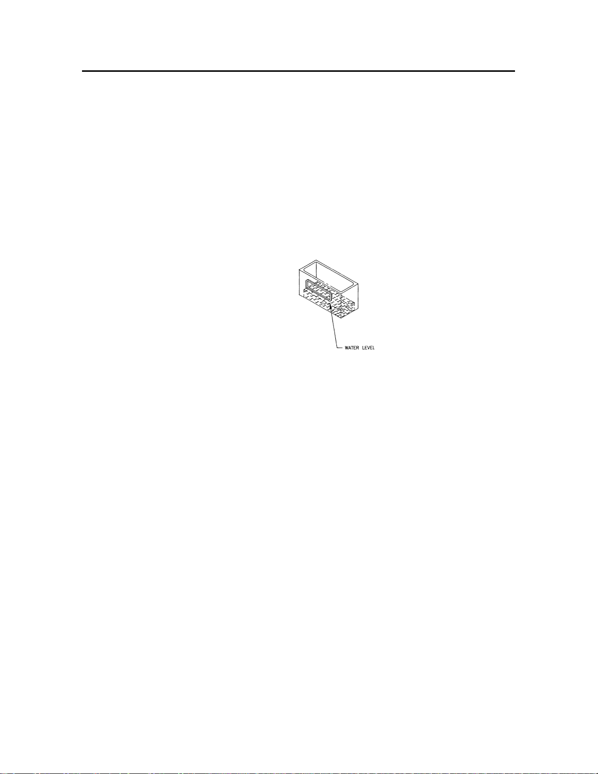
1) ______ Before power is turned on, open inlet water valve (field supplied & installed
near the back of the ice flaker) and check water level in sump. The water level
in the sump is the same as the return trough; it should be about half full (see
Figure 6 below).
Figure 6
Sump Water Level
2) ______ Make sure the ON/OFF switch is in the OFF position, then turn on the main
disconnect.
3) ______ Check voltage between line 1 and line 2, and verify that it is within nameplate
ratings.
4) ______ Turn the ON/OFF switch ON.
5) ______ Verify that the solenoid valve has opened (the valve will click loudly).
6) ______ Verify that the drive motor and water pump start.
7) ______ Verify that water is delivered to the distribution pan located inside the
evaporator.
- 20 -
5. Maintenance
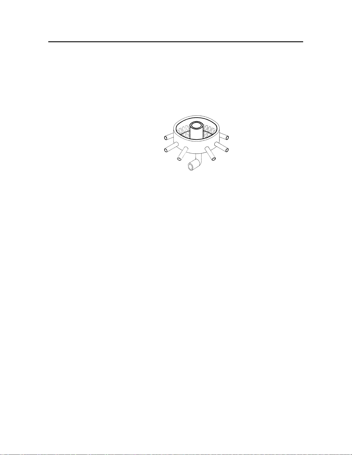
8) ______ Verify that the distribution pan water level is maintained at the half full point.
Open or close the water adjustment valve until the water level is maintained at
the proper level (see Figure 7 below)(20 ton model ice flakers have a
distribution ring).
Figure 7
Water Distribution Pan Water Level
9) ______ Allow 10-15 minutes to let the ice flaker come down to temperature and
balance out.
10) ______ Verify that ice is being frozen and harvested over the entire surface of the
evaporator. If it is, skip to step 14) below. If it is not, continue to the next
step.
11) ______ Check the suction pressure at the ice machine Suction temperature must be
maintained between -5°F & -20°F (depending on model flaker) at all times.
12) ______ Adjust Dual Pressure Regulator, Low range (operating) to 9-12PSIG (-5 to -
10°F), 3-6 PSIG (-20°F for 20 ton) High Range (relief) to 65-75 PSIG.
13) ______ Recirculated ammonia suction temperature is -5°F, Adjust the hand expansion
valve(s). Adjust the hand expansion valves to meter the correct amount of
Liquid to fill each circuit. Adjust the adjustment stem 1/8 to 1/4 turn at a time
(counterclockwise to open the valve if the evaporator was not freezing ice on
its entire length). Wait 10-15 minutes between each adjustment to allow the
valve and machine balance out. Repeat this step until ice is produced and
harvested all the way down to the bottom of the evaporator.
14) ______ When the ice maker is adjusted and operating properly, turn ON/OFF switch
OFF, and verify that the solenoid valve closes (the valve will click loudly).
15) ______ Verify that the off-delay is set correctly. After the ice flaker is turned OFF, the
drive motor and water pump will continue to operate for a period of time. This
should be adjusted to allow the drum to be cleared of residual ice after the
solenoid valve is de-energized. This ensures that, when the drive motor and
water pump stop, the evaporator will be free of ice. If necessary, adjust the
off-delay (see page 28 for location).
16) ______ Turn the ON/OFF switch ON.
- 21 -

5. Maintenance
17) ______ Verify operation of the photoeye level controls. Block the path of the infrared
beam. After a built-in 15 second delay, the shutdown cycle will begin. If the
ice flaker does not begin shutdown, adjust the photoeyes per instructions of
page 16.
18) ______ Unblock the photoeye beam, and verify that the ice flaker re-starts
immediately.
19) ______ Adjust the electronic overload setting (see page 28 for location). Slowly turn
the overload setting counterclockwise, just to the point that the flaker shuts
down on overload. Turn the overload adjustment ¼ turn clockwise, reset the
overload device, and re-start the flaker. This will insure that the drive motor is
adequately protected, but will not cause nuisance shutdowns.
20) ______ Verify that the ice flaker is adjusted and producing dry flake of ice.
21) ______ Verify that water is NOT dripping into the bin. If it is, locate the dripping
point and correct it (i.e., distribution pan overflowing, water recovery trough
overflowing, or distribution tubes broken or misaligned).
- 22 -
 Loading...