

Howden Roots RAS-J Whispair, Roots RAS Whispair Installation, Operation & Maintenance Manual
Page 1
www.howden.com
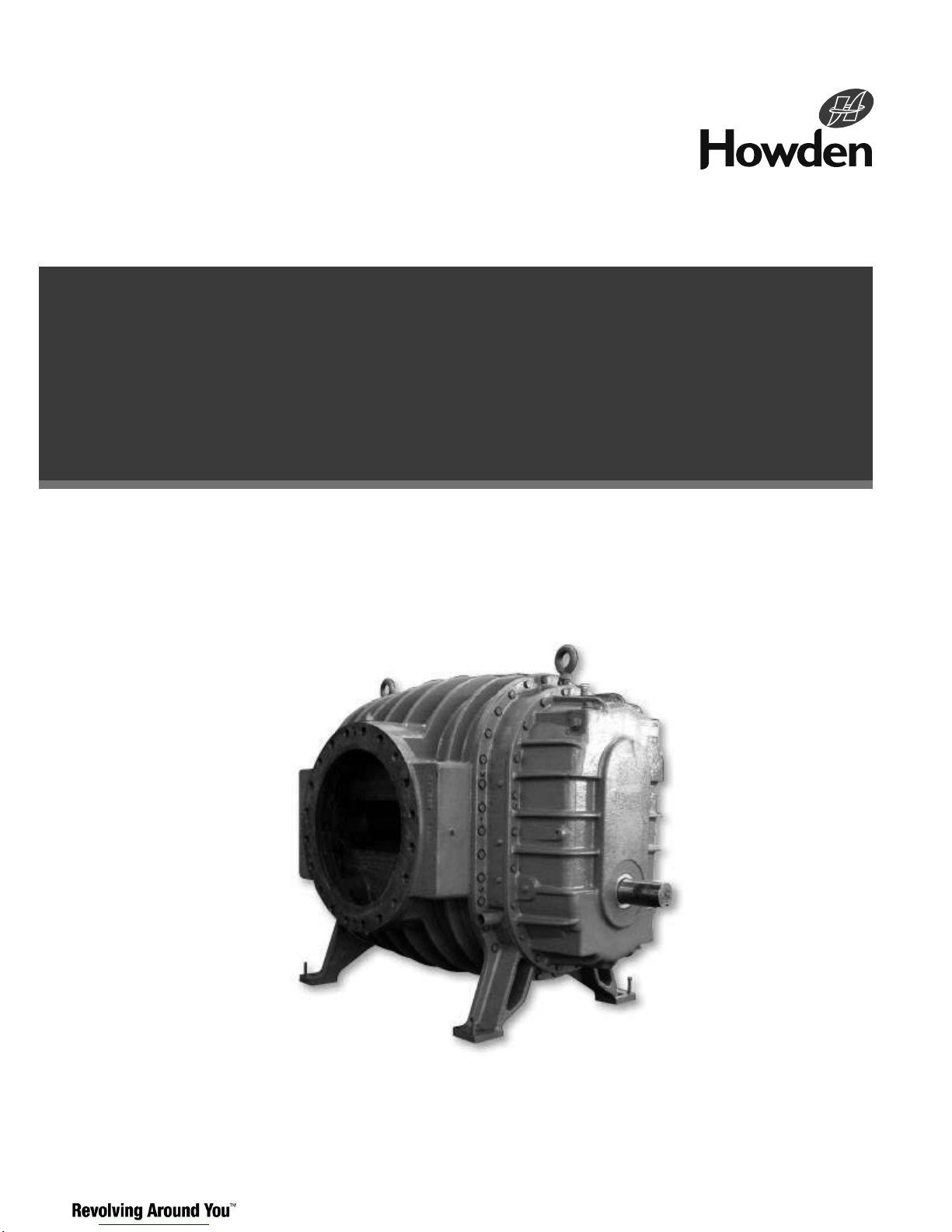
Roots* RAS and RAS-J
Whispair* Blower
10”-20” Splash Lubricated
Installation Operation & Maintenance Manual
Page 2

ILRB-3000 GEA20261 RAS and RAS-J WHISPAIR Blowers
Page 2 of 33
Contents
Information Summary ...................................................2
Operating Characteristics .............................................3
Operating Limitations ....................................................4
Installation .....................................................................6
Lubrication ...................................................................11
Operation......................................................................13
Safety Precautions ......................................................14
Preventive Maintenance .........................................14-15
Troubleshooting Checklist ...........................................15
Rotary Lube Blower Vibrations ....................................16
Maintenance/Replacements....................................16-22
Repair
Kit Information ..................................................22
Tables.................................................................... 23-24
Parts
Lists ....................................................................25
Assembly Drawings ................................................26-28
Do these things to get the most from your Roots Blower
❏ Check shipment for damage. If found, file claim with
carrier and notify Howden Roots.
❏ Unpack shipment carefully, and check contents against
Packing List. Notify Howden Roots if a shortage appears.
❏ Store in a clean, dry location until ready for installation.
Lift by methods discussed under INSTALLATION to avoid
straining or distorting the equipment. Keep covers on all
openings. Protect against weather and corrosion if outdoor
storage is necessary.
❏ Read OPERATING LIMITATIONS and INSTALLATION
sections in this manual and plan the complete installation.
❏ Provide for adequate safeguards against accidents to
persons working on or near the equipment during both
installation and operation. See SAFETY PRECAUTIONS.
❏ Install all equipment correctly. Foundation design just be
adequate and piping carefully done. Use recommended
accessories for operating protection.
❏ Make sure both driving and driven equipment is
correctly lubricated before start-up. See
LUBRICATION.
❏ In event of trouble during installation or operation, do not
attempt repairs of Howden Roots furnished equipment.
Notify Howden Roots
, giving all nameplate information plus
an outline of operating conditions and a description of the
trouble. Unauthorized attempts at equipment repair may
void Howden Roots warranty.
❏ Units out of warranty may be repaired or adjusted by the
owner. Good inspection and maintenance practices should
reduce the need for repairs.
NOTE: Information in this manual is correct as of the date
of publication. Howden Roots reserves the right to make
design or material changes without notice, and without
obligation to make similar changes on equipment of prior
manufacture.
Roots products are sold subject to Howden Roots general terms of sale and warranty policy; contact your nearest
Howden Roots office for more information.
Page 3
ILRB-3000 GEA20261 RAS and RAS-J WHISPAIR Blowers
Page 3 of 33
Operating Characteristics
The Roots air blowers described in this manual represent
both the basic type of Roots Anti-friction System (RAS)
rotary lobe arrangement and the proprietary Roots RAS
WHISPAIR design, with gear diameters ranging from 10 to
20 inches. All units are equipped with an effective splash oil
lubrication system.
The Roots RAS Blower
The Roots RAS rotary lobe blower is a positive
displacement unit; its pumping capacity is determined by
size, operating speed, and inlet conditions. It has two
double-lobe impellers mounted on parallel shafts and
rotating in opposite directions within a cylinder closed at the
ends by headplates. As the impellers rotate, air is drawn
into one side of the cylinder and forced out the opposite
side against the existing pressure. The differential pressure
developed depends on the resistance of the connected
systems.
Effective sealing of the blower inlet area from the discharge
area is accomplished using very small operating
clearances. This feature significantly reduces rubbing
contact between rotating and stationary parts, removing the
need for internal lubrication. Clearances between the
impellers during rotation are maintained by a pair of
accurately machined timing gears mounted on the two
shafts that extend outside the air chamber.
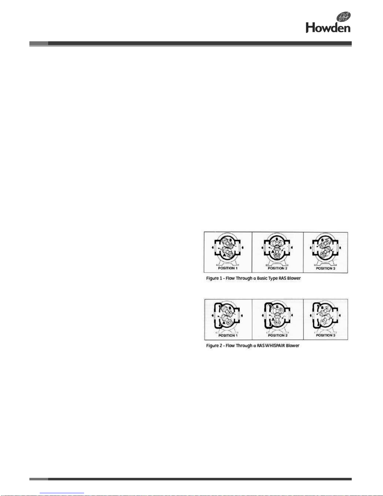
Operation of the RAS rotary lobe blower is illustrated in
Figure 1, where air flow is from right to left from inlet to
discharge, with the lower impeller rotating clockwise. In
Position 1, it delivers a known volume (A) to the discharge,
while the space (B) between the upper impeller and
cylinder wall is being filled. Counterclockwise rotation of
this impeller then traps an equal volume (B) in Position 2,
and further rotation delivers it to the discharge in Position 3.
At the same time, another similar volume is forming under
the lower impeller, and will be discharged when rotation
reaches Position 1 again.
One complete revolution of the driving shaft alternately
traps four equal and known volumes of air (two by each
impeller) and pushes them through to the discharge. The
pumping capacity of a lobe blower operating at a constant
speed therefore remains relatively independent of
reasonable inlet or discharge pressure variations. To
change the capacity it is necessary to change the speed of
rotation or vent some of the air.
The Roots RAS WHISPAIR
Operation of the proprietary Roots RAS WHISPAIR blower
is represented in Figure 2. Just as in the standard Roots
RAS blower, the air flow is from right to left, with the lower
shaft rotating clockwise. This design differs from the basic
RAS rotary blower in that it provides a chamber on the
discharge side of the cylinder.
From this chamber, two or more slots open back into the
two alternately closed pocket areas of the cylinder (shown
as A and B). These slots, at certain impeller positions,
allow discharge pressure to bleed into the normally low
pressure pockets. They also provide a jet action on the
impellers in the direction of rotation. Gradual pressure
build-up in the pockets, to a level almost equal to the
discharge pressure, reduces the backflow rate at the
instant of pocket discharge, effectively minimizing pulsing
and shock noise.
As shown in Position 1 in Figure 2, the known volume (A) is
delivered to the discharge chamber while the space (B) is
filled with an equal volume at inlet pressure. In Position 2
the space has been sealed from an inlet, but some
discharge pressure is entering the space (B) through the
slot passage, as indicated by the small arrows. The force of
the jet assists the rotation of the impeller, while also
building pressure in the sealed space (B). Rotation
continues to Position 3, where the volume (B) is delivered
to the discharge chamber in the same manner as the
volume (A) in Position 1. Because of the almost complete
pressure equalization through the slot, shock is minimized.
Notes and Warnings
With either blower design, no attempt should ever be made
to control capacity by means of a throttle valve in the intake
or discharge piping. This increases the power load on the
driver and may seriously damage the blower. Similarly, if a
possibility exists that flow to the blower inlet may be cut off
during normal operations, then an adequate vacuum relief
valve should be installed in the inlet line near the blower. A
pressure relief valve in the discharge line near the blower is
also strongly recommended for protection against cut-off or
blocking in this line.
When a belt drive is employed, blower speed can usually
be adjusted to obtain the required capacity by changing the
diameter of one or both sheaves. In a direct-coupled
Page 4

ILRB-3000 GEA20261 RAS and RAS-J WHISPAIR Blowers
Page 4 of 33
arrangement, a variable speed motor or transmission is
required, or air may be vented through a manually
controlled unloading valve and silencer. If discharge air is
returned to the blower inlet, it must go through a cooling bypass arrangement.
Before making any change in blower capacity or operating
conditions, contact the nearest Howden Roots office for
specific information applying to your particular blower. In all
cases, operating conditions must be maintained within the
approved range or pressures, temperatures and speeds as
stated under LIMITATIONS. Also, serious damage to the
rotating parts of the blower will result if it is used to handle
air that contains liquids or solids.
Operating Limitations
A Roots blower must be operated within certain approved
limiting conditions to enable continued satisfactory
performance. The Howden Roots warranty is contingent on
such operation.
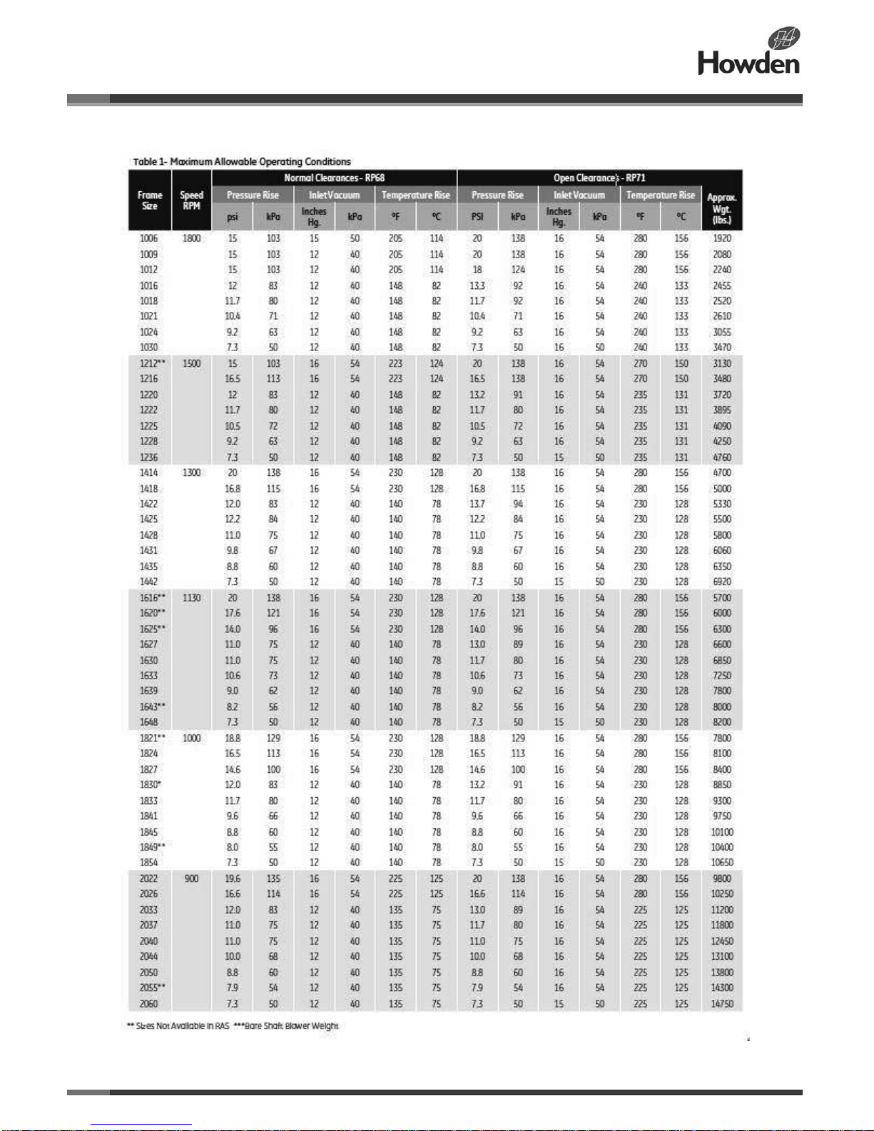
RAS/RGS and RAS/RGS WHISPAIR blowers are available
with two types of internal blower clearances, normal and
open. Maximum limits for pressure, temperature, vacuum,
and speed are specified in Table 1 for both types of
clearances. Verify with the factory that your blower is
supplied with open clearances before operating it within the
specified conditions. Table 8 lists the values of normal
clearances and Table 9 lists the values of open clearances.
Do not exceed any single limit or combination of limits
listed in Table 1.
Be sure to arrange connections or taps for thermometers
and pressure or vacuum gauges at or near the inlet and
discharge connections of the blower. These, along with a
tachometer, will enable periodic checks of operating
conditions.
Note: Some special purpose blowers may be assembled
with non-standard clearances other than those shown in
Table 8 or 9. These units may be operated at pressure and
or temperature rises higher than those listed in applicable
Table 1. However, you must request specific approval from
the nearest Howden Roots office before doing so,
otherwise the warranty will be voided. Normally, when a
blower is operated at the design conditions stamped on its
nameplate, the specified limits apply.
Pressure- The pressure rise, between blower inlet and
discharge, must not exceed the figure listed for the specific
unit frame size concerned. Also, in any system where the
unit inlet is at a positive pressure above atmosphere, a
discharge pressure of 25 PSI (172 kPa) should not be
exceeded, regardless of blower size.
On vacuum service, with the discharge to atmospheric
pressure, the inlet suction or vacuum must not be greater
than the values listed for the specific frame size.
Temperature - Blower frame sizes are approved only for
installations where the following temperature limitations can
be maintained in service:
• Measured temperature rise must not exceed listed values
when the inlet is at ambient temperatures. Ambient is
considered as the general temperature of the space around
the blower. This is not outdoor temperature, unless the
blower is installed outdoors.
• If inlet temperature is higher than ambient, the listed
allowable temperature rise values must be reduced by twothirds of the difference between the actual measured inlet
temperature and the ambient temperature.
Speed- Blowers may be operated at speeds up to the
maximums listed for the various frame sizes. They may be
directly coupled to suitable constant speed drivers if
pressure/temperature conditions are also within limits. At
low speeds, excessive temperature rise may be a limiting
factor.
Special Note: The listed maximum allowable temperature
rise (increase in air temperature between inlet and
discharge) for any particular blower may occur well before
the maximum speed or maximum pressure rating is
reached. This may occur at high altitude, low vacuum or
very low speed. The unit’s operating limit is always
determined by the maximum rating reached first −
pressure, temperature, or speed.
Page 5
ILRB-3000 GEA20261 RAS and RAS-J WHISPAIR Blowers
Page 5 of 33
Page 6

ILRB-3000 GEA20261 RAS and RAS-J WHISPAIR Blowers
Page 6 of 33
Installation
Supervision of the installation by a Howden Roots service
engineer is not usually required for these units. Technicians
with general experience in installing heavy machinery
should be able to produce satisfactory results. However, a
Howden Roots service engineer may be engaged for
assistance or for final checking of an installation.
Note: The information contained in this manual is intended
to supplement more detailed discussions of foundations
and piping found in API recommended practice 686 and the
Compressed Air and Gas Handbook, published by the
Compressed Air and Gas Institute, New York City, and the
American Petroleum Institute, Washington, D.C.
Location
Because the unit is completely enclosed, the location of the
installation is typically not critical. While a clean, dry, and
protected indoor location is preferred, an outdoor location
will generally provide satisfactory service. Important
requirements are that the correct grade of lubricating oil be
provided for the expected operating temperatures, and that
the unit is located so that routine checking and servicing
can be conveniently performed.
Protection
As indicated by markings on the flange covers, the internal
machined surfaces of Roots blowers are treated with a
vaporizing inhibitor after factory assembly to protect against
normal atmospheric corrosion. Protection against chemical
or saltwater atmosphere is not provided.
The maximum period of protection is one year under
average conditions, if flange covers and closing seals are
not removed. Leave covers and tape seals over all
openings as long as possible during installation to avoid
loss of protection.
If there will be an extended period between installation and
start-up, take the following steps to ensure corrosion
protection:
1. Coat the insides of the cylinder, gearbox, and drive end
bearing covers with a vapor phase rust-inhibiting liquid
such as Nox-Rust VCI-10 or equivalent. Repeat once a
year or as conditions require. VCI-10 is oil soluble and
does not have to be removed before lubricating. If desired,
Nox-Rust VCI-10 may be removed from within the cylinder
shortly before start-up by spraying a fi ne mist of petroleum
solvent through the blower while it is running at a slow
speed with open inlet and discharge, or it can remain in the
blower if it is not harmful to the operation of the connected
system. Nox-Rust VCI-10 may be obtained from Daubert
Chemical Co., 2000 Spring Rd., Oak Brook, IL, 60521.
2 Paint the shaft extension, inlet and discharge flanges,
and all other exposed surfaces with Nox-Rust X-110 or
equivalent.
3 Seal the inlet, discharge, and vent openings. It is not
recommended that the unit be set in place, piped to the
system, and allowed to remain idle for extended periods. If
any part is left open to the atmosphere, the Nox-Rust VCI10 vapor will escape and lose its effectiveness.
4 Protect the equipment from excessive vibration during
storage.
5 Rotate the drive shaft three or four revolutions every two
weeks.
6 Prior to startup, remove the fl ange covers on both the
inlet and discharge and inspect the interior to ensure the
absence of rust. Check all internal clearances. Also,
remove the gearbox and bearing covers and inspect the
gear teeth and bearings for rust.
Before connecting the piping, remove the main flange
covers and inspect the blower interior for the presence of
foreign particles or dirt adhering to machined surfaces. Use
petroleum solvents to carefully wash away any material
found and then manually rotate the impellers to ensure that
they turn freely. Use the same solvent to remove the
antirust coating from the fl ange faces and any other
surfaces. Note: Interior cleaning is not required if no dirt is
found.
Equipment Handling/Lifting
Handling of the Root blower equipment needs to be
accomplished with care, and in compliance with safe
practices. The weight of a bare unit, without the base plate,
driver, or accessories, ranges from about 1 ton (910 kg) for
the smallest units to approximately 7 tons (6350 kg). On
RAS and RAS-J units, an eyebolt is provided near each
end for lifting. Units mounted on a base plate have greater
weight and should always be handled using the four lifting
hooks provided.
Check the eyebolts for tightness, by tapping with a
hammer, before lifting the equipment by the eyebolts. Make
sure to pull the bolts in a nearly vertical direction when
lifting. To ease the side strain caused by a large cable
angle, place a stiff spreader between the eyebolts and
adjust the cable lengths so that the unit is approximately
level during the lift.
Note: A harness with four lifting hooks is required to lift
base-mounted units. After inserting the hooks in the lifting
lugs, block the chains out on the sides to avoid placing the
unit under strain. At the same time, adjust the lengths to
produce a level lift.
Foundation
Because many factors, including local soil conditions,
impact the foundation design, this section offers only a
Page 7
ILRB-3000 GEA20261 RAS and RAS-J WHISPAIR Blowers
Page 7 of 33
general discussion that is intended to be supported by
information from the Compressed Air and Gas Handbook
referenced earlier. To ensure satisfactory equipment
operation, the concrete foundation must be rigid, have
minimal defects, and should not be resonant in the
frequencies of the operating speed range of the equipment.
The foundation’s length and width must provide at least
6 inches (150 mm) from any edge to the nearest
machine anchor bolt (based on the location indicated in
the certified manufacturer’s general arrangement
drawing). The depth dimension should be determined by
design, with a minimum practical depth considered to be
twice the distance between the shaft centres (or gear
diameter) of the unit, or sufficient depth to attain a
concrete mass a minimum of one-and-a half times the
weight of the blower and motor.
The concrete block needs to cure for a minimum of 28
days before the blower is grouted in place. Any block
distortions during curing will have little or no effect on
equipment and alignment. To simplify machine levelling
and provide a good grouting bond, the top of the
foundation should be struck off as level as possible, but
left with a rough surface.
We do not recommend spring-type vibration isolating
mounting for use directly between the operating
equipment and the foundation. When such mountings
are required, they should be designed to carry a
reinforced concrete slab on which the equipment is
mounted. The slab must offer good rigidity against
bending and twisting. The suspension system requires
careful adjustment to produce a reasonably level
condition during operation. All piping requires flexible
sections and supports to reduce connection strains on
the unit.
We also do not recommend the direct use of structural
framing members for mounting the blower base to a
building structure. If this is unavoidable, it should be
restricted to smaller frame size units, and spring-type
mountings should not be used. Structural members
must be rigid, and will probably require reinforcement if
they are part of a building. Noise transmission can be
reduced by using a cork isolation pad to reduce the
transfer of vibration from the blower base to the building
structure. The pad should be 1 to 2 inches (25-50 mm)
thick, bedding on a full steel plate attached to the
structure and carrying the rigid concrete slab on which
the equipment is mounted.
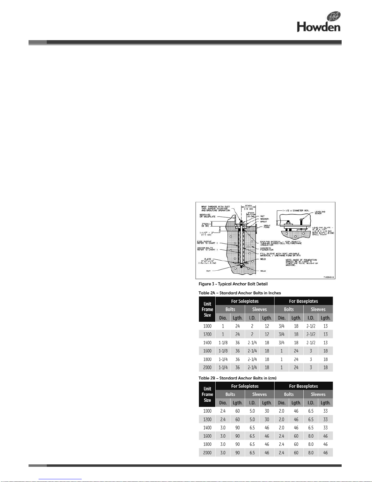
Anchor Bolts and Plates - Place anchor bolts within
the foundation forms before the concrete is poured.
(See Table 2 for the recommended bolt sizes and
Figure 3 for proper bolt installation.) The bolts must be
located as accurately as possible based on the
dimensions provided on the certified installation
drawing. To obtain a bolt location tolerance of 1/8-inch
(3mm), use drilled templates firmly secured to the
foundation forms.
It is important to keep the bolt sleeves centered around
the bolts and free of concrete to allow the bolts to be
sprung enough to correct for small variations in bolt
setting and machine drilling. The sleeves are filled in the
final grouting operation. Adjust the bolt positions
vertically so that the top ends extend at least one-and-ahalf diameters above the soleplate or taper washer, or
as shown on the installation drawing.
Use the provided jack screws for easier height
adjustment levelling. Place steel plates, approximately
4” x 4” x 1/2” (100 x 100 x 13 mm, on the foundation
under each jack screw location. Plates and anchor bolts
are not furnished as standard accessories.
Page 8

ILRB-3000 GEA20261 RAS and RAS-J WHISPAIR Blowers
Page 8 of 33
Levelling
Because the unit should be as level as possible in all
directions, we recommend performing this critical step
using a good quality machinist’s level with a ground glass
bubble vial. Level the blower from the drive shaft and pipe
flanges.
Machined baseplates have pads running along both the
length and width. On soleplates, the machined top surfaces
are used for levelling. Scrape the pads or surfaces clean,
and use a flat file to remove burrs on the high points.
When the blower and driver are factory mounted on a
common baseplate, treat the assembly as a unit for
levelling purposes. Use the jack screws to establish the
grouting space under the base flanges and to level the
base. Adjust the screws until the indicated variation from
the level does not exceed .001 inch per foot (.08 mm per
meter) in either length or width. To reduce twist, any
variations should all be in the same direction. The
maximum allowable twist is .001 inches per horizontal foot
(.08 mm per horizontal meter) measured between any two
sections of the base.
Units that are mounted on soleplates can be levelled in a
similar manner. The plates should be large enough to
provide extensions for levelling in both length and width on
the finished upper surfaces. Solidly fasten the plates to the
blower feet, which are machined flat and parallel to each
other. Then install and level the blower carefully, using jack
screws, shims, or wedges for adjusting. It is very important
to eliminate twist. Minor adjustments can be made by
placing shims directly under the blower feet. When a
satisfactory level condition is obtained, turn the anchor bolt
nuts down snug, but not tight.
Aligning
When the blower unit and its driver are direct coupled,
careful attention is required to align the drive shafts.
Precise alignment helps ensure satisfactory coupling
operation, as well as significantly reducing the chance of
damage to either the driving or driven unit from vibration or
thrust forces.
For package units with the driver and blower mounted in a
common baseplate, the two shafts have been placed in
approximate alignment at the factory. Because baseplate
deflections can occur during shipping and installation, it is
important to obtain a close coupling alignment during
levelling to ensure that only small final adjustments will
need to be made after grouting.
For soleplate applications, the separately mounted driver
must be positioned, levelled, and aligned during
installation. Whether the unit is on soleplates or its own
base, place shims (1/16 to 1/8 inch (2-3 mm) thick) directly
under the driver feet before setting the unit in place to
achieve more accurate final alignment. Establish spacing
between the two shaft ends as required by the coupling. If
a motor is being used that has end play in the shaft, be
sure its rotor is located on magnetic center before setting
this spacing. It also needs a limited end fl oat kit.
When the blower is driven through V-belts, the driver must
be mounted on an adjustable base to permit tightening or
removing of the belts. In this case, the driver shaft height is
of no concern, but it must be parallel to the blower shaft
and level. To position the driver properly, mount both
sheaves on their shafts (the shaft center distance must be
known).
Install the narrow hub type of blower sheave (usually the
one with a larger diameter) so that its inner hub face is not
more than 1/4 inch (6 mm) away from the bearing housing
end cover. The driver sheave should also be mounted as
close to its bearing as possible. Position the driver so that
the faces of the two sheaves are accurately in line, with the
adjustable base located so that two-thirds of its total
available movement is in the direction away from the
blower.
This positioning provides minimum belt wear and slip, and
allows sufficient adjustment for installing and tightening the
belts. Do not install the belts until the grouting has set and
the anchor bolts are tightened.
Blowers to be driven by v-belts may be provided with an
extended drive shaft and an additional outer bearing to
handle the side pull of the drive. Identified by the extended
housing for the outer bearing, these blowers can also be
driven by direct coupling to the motor if necessary.
Note: Blowers intended specifically for direct coupling
have no outer bearing, and can be seriously damaged if
used for belt drive applications. Consult your Howden
Roots sales office before belting these units.
Grouting
The final levelling step − and a preliminary alignment step −
involves grouting the foundation.
After proper curing, create a roughened top surface by
chipping away glazed areas and removing oil or grease
using a strong hot detergent or caustic solution.
Grouting compensates for surface irregularities in the
foundation and machine base and also helps restrain
shifting. Because anchor bolts are used for hold-down only,
the grout under the soleplate or base flange must be
adequately thick, it must flow into the anchor bolt sleeves
and all interior cavities, and it must be a variety that offers
minimal shrinkage during the setting period. Due to the
open frame design, the bedplate should be filled with
concrete that is level with the top of the main channels.
Special grouting materials designed to counteract
shrinkage are commercially available and are often
preferred to cement. Follow the manufacturer’s instructions
Page 9
ILRB-3000 GEA20261 RAS and RAS-J WHISPAIR Blowers
Page 9 of 33
when using these materials. Care must be exercised when employing non-shrink additives with cement, as too much
can be worse than none. Any gas-forming or air-entraining
additives should be avoided, because they tend to reduce
grout strength.
Wait at least 24 hours before tightening anchor bolts or
connecting piping. When jack screws have been used for
levelling, make sure the bottom of the levelling screw is
treated according to the grout manufacturer’s instructions
so that it can be backed off. Such points of concentrated
loading are likely to wear during machine operation,
resulting in loose anchor bolts. Final bolt tightening should
only be enough to hold the machine firmly against the
foundation and prevent vibration.
After all anchor bolts are secured, recheck the blower for
twist and level. Working from the finished pad on top of the
cylinder, make corrections to meet the requirements
specified under LEVELING by shimming under the blower
feet. Then rotate the drive shaft by hand to make sure both
impellers turn freely at all positions.
When the blower is directly coupled to its driver, final
alignment of the two shafts should be accomplished by
very carefully adjusting the shims under the driver feet.
While a flexible coupling can accept some degree of
misalignment, it should not be forced to compensate for
careless workmanship. The flexing or sliding member in a
coupling transmits undesirable forces between the two
shafts in proportion to the degree of misalignment, thus
promoting vibration and unnecessary wear problems.
The two basic types of misalignment − offset and angular −
often occur together. Use the following limits to achieve
satisfactory coupling operation: maximum deviation in
offset alignment not greater than .005 inches (.13 mm) total
indicator reading on the coupling hubs, and maximum
deviation from parallel of the inside coupling faces not
greater than .001 inches (.03 mm) when checked at six
points. When the driver is a steam turbine, the final
alignment should be made with the turbine at operating
temperature in order to allow for shaft movement resulting
from expansion.
Piping
Before connecting the piping, thoroughly clean it. The
piping should be sized so that air velocity in the line does
not exceed 100 feet per second (30 m per second). When
a blower is operated at or near its maximum volume rating,
the piping should be no smaller than the blower
connections.
Use long radius elbows whenever possible to ensure
smooth flow. Design the piping layout so that no strain is
placed on the blower, either from weight or expansion
forces. Provide adequate supports, anchors, and
expansion joints or loops.
We recommend installing a spool-type rubber expansion
joint near the blower inlet connection. In addition, a similar
unit with control elements added to minimize piping
vibrations may be required near the discharge. Depending
on the blower speed, operating pressure, length and type
of piping, and surrounding area sound level requirements,
the use of snubbers or silencers in
the inlet or discharge piping may be necessary. For specific
silencer recommendations, contact your nearest Howden
Roots sales office.
Typically, inlet piping should be free of valves or
restrictions, but when a shutoff valve cannot be avoided,
make sure a full-size vacuum relief valve is installed near
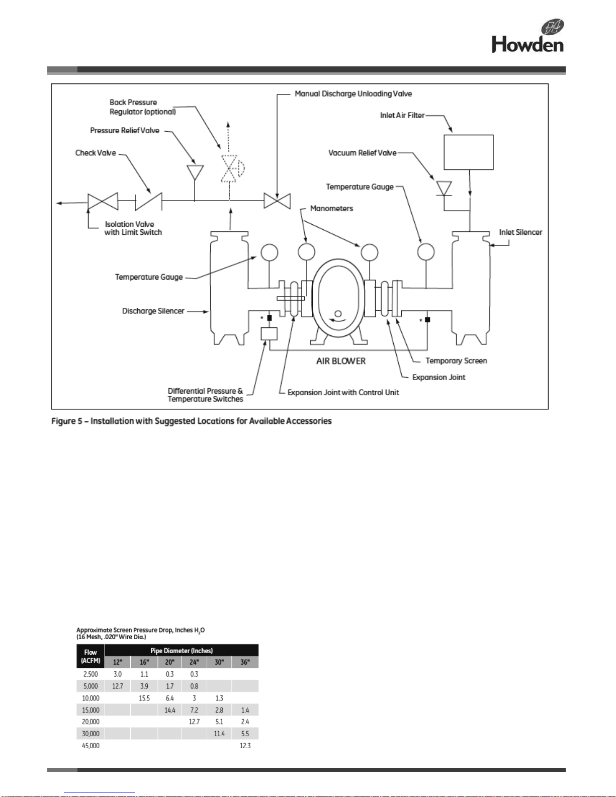
the blower inlet connection (see Figure 5). This will protect
against an overload caused by accidental valve closing.
Further protection can be provided by installing a
dependable pressure-sensitive device with an alarm or
shutdown action.
During initial operation, install a temporary corrosionresistant screen at the compressor inlet connection. The
screen should be made of 16 mesh (.020 inch diameter)
wire backed with 2 mesh wire cloth. The backing cloth-wire
diameter should be a minimum of:
• 0.063 inch diameter for 12-inch pipe
• 0.080 inch diameter for 16-inch pipe
Page 10
ILRB-3000 GEA20261 RAS and RAS-J WHISPAIR Blowers
Page 10 of 33
• 0.105 inch diameter for 20-inch pipe
• 0.120 inch diameter for 24-inch pipe
For 30” and 36” pipe use 1 mesh backing cloth with a
minimum of 0.180-inch wire diameter for 36-inch pipe.
The table below provides the approximate screen pressure
drop. To determine when the piping needs to be cleaned,
connect a manometer to measure the pressure drop across
the screen. Do not allow the pressure drop to exceed 55
inches H2O. Clean and replace the screen until debris no
longer appears, and then remove the screen. Typically,
screens are installed for the first one to two days of
operation. If the screen is left in place, the wire will
eventually deteriorate and wire fragments may enter the
blower and cause serious damage.
Discharge piping requires a pressure relief valve, and
should also include a suitable pressure gauge and a
manually operated unloading valve. The unloading valve
permits starting under no-load conditions. The optional
back pressure regulator shown in Figure 5 is required if
volume demands vary while the blower operates at a
constant speed. It may be vented if only air is being
handled. Depending on permissible sound levels in the
general surroundings, a vent silencer may be required.
In some installations, particularly when two or more
blowers discharge into a common header, we recommend
that a direct acting or free swinging check valve be
provided in each discharge line. These valves protect
against damage resulting from reverse rotation caused by
back flow through an idle blower.
Carefully line up the mating flanges when making pipe
connections to the blower. They must contact squarely and
accurately, without imposing strain on the blower casing.
Any attempt to draw flanges together by force will likely
distort the blower and cause internal contacts. The blower
should not carry more than the weight of one pipe fitting at
each connection. After bolting up the flanges, rotate the
drive shaft by hand to check for rubbing contacts caused by
strains or dirt.
Page 11

ILRB-3000 GEA20261 RAS and RAS-J WHISPAIR Blowers
Page 11 of 33
Lubrication
Separate Opposite Gear End Reservoirs
Roots blowers use a simple and reliable splash lubrication
system. All friction parts -- gears, bearings, and shaft seals
− are lubricated by dipping them directly into oil reservoirs
or by splash oil from other rotating parts. All reservoirs
require the same grade of oil as specified in Table 3 for
various ambient temperature ranges at the installation site.
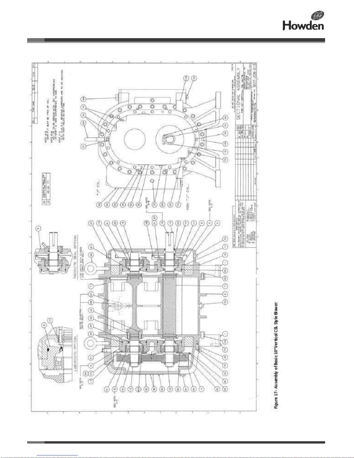
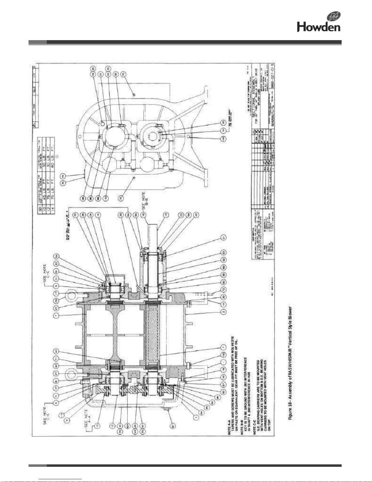
Reference the appropriate assembly drawing in Figure 15
to better understand the following discussion.
At the opposite gear end of the blower, the upper (or
driven) shaft bearing is lubricated from its own oil reservoir,
formed by the bearing carrier (6) and the deep blind end
cover (5A).
At a normal oil level, bearing rollers dip into the oil as they
roll through the bottom of their raceway. The oil picked up
is carried over the top by bearing rotation, and some of it
transfers to the shaft behind the bearing to lubricate the
dynamic lip-type inboard seal (27). A slight amount of oil
may work through this seal, but it will be thrown off by the
shaft slinger, and it will be further prevented from reaching
the air chamber by a labyrinth-type seal where the shaft
passes through the headpiece. The chamber between the
two sealing points is vented to atmosphere and serves not
only to drain any seal leakage but also to keep the
lubrication system at atmospheric pressure.
At the lower (driving) shaft, the arrangement is the same as
described above when a short shaft for direct coupling is
provided. An outboard shaft seal (23) is provided in the end
cover (5). On V-belt driven blowers, the drive shaft and
bearing carrier (63) are extended and provided with an
additional inboard bearing (60). This creates a larger
reservoir requiring about three times as much oil to fi ll.
Lubrication is the same as for the shorter shaft, except that
two protruding screws (96) are provided to ensure
adequate splash oil for the bearing (60).
At the gear end of the blower, the bearings, seals, and
timing gears are enclosed by a gearbox containing a
double (primary and secondary) oil sump arrangement. In a
vertical-style blower, the secondary sump is formed of
sheet steel and contoured around the bottom half of the
lower gear. It is fed with oil at a controlled rate from the
surrounding primary sump in the gearbox itself, through a
metering orifice in the secondary wall. The lower gear teeth
pick up oil and carry it to the meshing point with the upper
gear, where it is splashed onto oil control shields with
leaders that direct the oil to the two bearings. A dam at
each bearing maintains the desired oil level there, with
excess overflowing into the gearbox primary sump. Inboard
sealing of the shafts is the same as at the drive end. In a
horizontal style blower, the gear end lubrication
arrangement is identical, except that a secondary sump is
formed around each gear and the total oil capacity is more
than doubled.
Note: A high-quality grade of industrial-type non-detergent,
anti-foaming oil should be used when the average of
blower inlet and discharge temperature is 125°F (52°C) or
lower. Oil should be changed after the first 100 hours of
operation. After the initial oil change, the normal oil change
periods under these conditions are every 2,000 operating
hours. At higher temperatures these oils may turn black
and leave carbon deposits. For average temperatures
above 125°F (52°C), we recommend that oil with an
efficient oxidation inhibitor be used, and that the change
interval should be reduced. Shell TELLUS is a suitable oil
type with the required characteristics. Equivalent oils from
other suppliers are assumed to be comparable in
performance.
Suggested oil change periods for the higher operating
temperatures are as follows:
Average Temp. °F (C°) Operating Hrs.
Below 150 (65) 1000
151-160 (66-71) 500
Above an average temperature of 180°F, a synthetic oil like
Roots* Synfilm ST Synthetic Oil should be used.
On the gearbox and the two opposite gear end bearings
sumps, oil levels are indicated in sight windows. All three
sight windows are completely unobstructed circular discs,
allowing the oil level to always be in view.
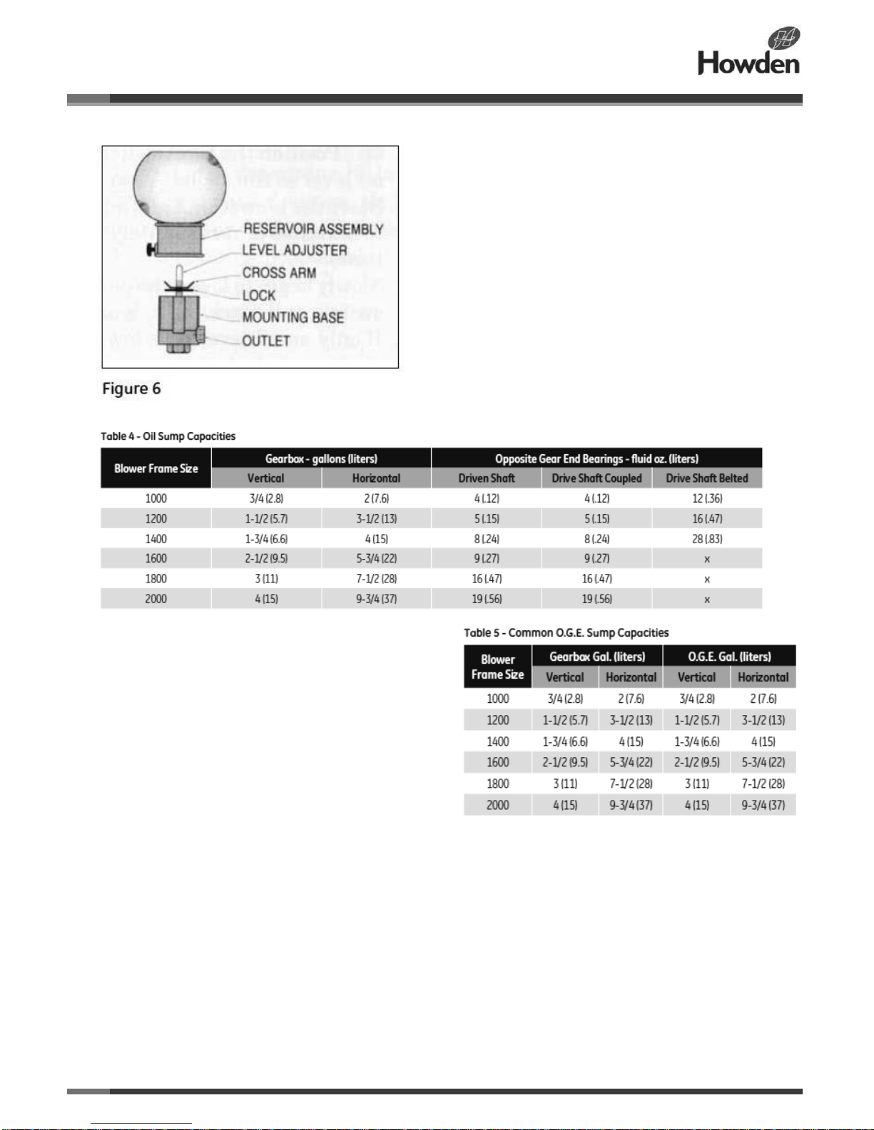
Approximate capacities in gallons or fluid ounces for the
three sump locations are given in Table 4 as a guide.
Actual filling requirements may vary slightly from the listed
figures.
Select a good industrial grade of oil per Table 3 for your
existing ambient temperature conditions.
To establish the correct oil levels, fill the oil sump when the
blower is not operating. At the gearbox, remove the top
vent plug (37) and pour in slightly less oil than indicated in
Table 4 for the appropriate blower size, or add the oil until it
rises to the center of the sight glass. Wait several minutes
for the levels to equalize between the primary and
secondary sumps, then add more oil if needed, or drain
excess at the plug (67).
Page 12
ILRB-3000 GEA20261 RAS and RAS-J WHISPAIR Blowers
Page 12 of 33
The opposite gear end sumps use constant level oilers. To
fill the sumps, remove the top glass reservoir. Fill it with oil,
place it on its holder, and let the bottle empty to fill the
sump. To obtain proper oil level in the sump that is toward
the center of the sight glass (90), pull out the level adjuster
(A) shown in Figure 6 and raise or lower the cross-arm (B)
as needed. Secure the cross arm with the lock (C), drop
the assembly back into the lower reservoir, and replace the
bottle. Note: Raising the cross arm (B) raises the oil level
and lowering it lowers the oil level.
During operation the sump levels can be expected to
fluctuate. At the gearbox sight window the level will rise as
a result of oil being thrown out of the secondary sump (oil
pan) into the primary sump. A satisfactory oil level is
assured as long as it is visible in the window. A blower
should not be operated when the oil is either above or
below the circle on the sight window.
Oil levels at the opposite gear end will fall slightly during
operation because of the apparent “loss” carried in the
bearings and on the shafts. If the level is visible in the sight
glass, a satisfactory amount of oil is present.
During the fi rst week of blower operation, check the oil
level daily and watch for leaks. Replenish oil as necessary.
Thereafter, an occasional check should be sufficient. Drain
plugs (67 and 88) are provided at the bottom of the
gearbox and bearing sumps.
Common Opposite Gear End Reservoirs
Some blowers are equipped with a common reservoir on
the opposite gear end. The small reservoirs are replaced
with a large cover similar to that covering the gear end.
The oil is transmitted to the bearings by use of a slinger
plate that dips into the oil. The oil is then captured and
directed to the bearings by oil control shields. Refer to the
sectional drawings at the back of this manual for help in
better understanding this system.
The lubrication of the gear end of the blower is accurately
described in the previous section. Refer to Table 5 to
determine the approximate opposite gear end oil sump
capacity.
Some blowers using the common O.G.E. reservoir are
supplied with oil level switches. The recommended
procedure for setting these switches is as follows:
1 Prior to starting the blower:
• Add oil to the reservoirs until the level is in the center of
the bullseye sightglasses.
• Disconnect the level switch from the blower shut down
system.
• Position the level switch slightly above the oil level so the
switch is not as yet reset.
Page 13

ILRB-3000 GEA20261 RAS and RAS-J WHISPAIR Blowers
Page 13 of 33
2 Start the blower and allow the oil temperature to stabilize
(approximately 1/2 hour running time).
3 Slowly begin to lower the position of the oil level switch
and mark the height at which it resets.
4 If only an oil level shutdown is to be used, continue to
lower the switch until it is 3/4 inch below the position where
the switch is reset, and lock it in place.
5 If an oil level alarm is to be used jointly with a shutdown,
lower the switch 1/2 inch below the point where the alarm
switch is reset, and lock it in place.
Lip seal oil leakage - A small amount of oil seal leakage
always occurs at the drive shaft seal and the headplate
seals because the unit requires this film under the lip for
proper operation. This oil should be wiped off of the blower
and base plate surfaces periodically, to prevent build-up.
Operation
Before operating a blower for the first time, thoroughly
recheck the unit installation using the following
procedure checklist as a guide. In addition, make sure
to consider any special conditions of your installation.
1 Ensure that no bolts, tools, rags, or debris have been
left in the blower air chamber or piping.
2 If you are using an outdoor intake without a filter,
ensure that the opening is clean and protected by a
strong screen. Use of a temporary protective screen at
the blower inlet as described under INSTALLATION is
strongly recommended during early operation.
3 If the installation was not performed recently, recheck
the blower leveling, drive alignment, belt tension, and
tightness of all mounting bolts.
4 Hand turn the drive shaft to make sure that the
impellers rotate without bumping or rubbing at any point.
5 Check that the blower lubrication system oil levels are
at the center of the sight glasses.
6 Check that the driver (and gear unit if supplied) is
properly lubricated. Make sure that power is available
and that all electrical overload and safety controls are
installed and workable.
7 Open the manual unloading valve in the discharge air
line. Make sure that any blocking valve in the inlet piping
is open.
8 Bump the blower a few revolutions with the driver to
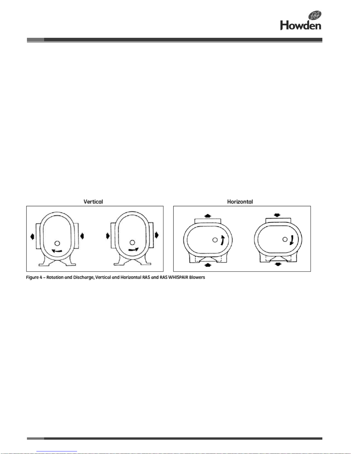
ensure that the direction of rotation agrees with the
arrow near the blower shaft and to make sure that both
units coast freely to a stop.
After completing the check list items above, the blower
is ready for trial operation under “no-load” conditions.
The following procedure is suggested for this initial
operation test period.
9 S
tart the blower, let it accelerate to full speed, and
then shut it off. Listen for any knocking sounds, both
with the power on and also as it slows down.
10 If no problems have been noted, after the blower
comes to a complete stop, restart the unit and let it
operate for 5 to 10 minutes under no-load conditions.
Feel all of the cylinder surfaces for any hot spots
indicating impeller rubs. Continue to listen for noises
and watch for changes in vibration.
11 If all conditions are acceptable, continue operating
the unit, while gradually closing the discharge unloading
valve to replicate normal operating conditions as closely
as possible. We recommend using high-quality pressure
and vacuum gauges and thermometers in both inlet and
discharge locations to measure pressure and
temperature rises across the blower. Observe the
pressure increase as the unloading valve is closed, and
do not allow it to exceed the rating of the specific blower
as listed under LIMITATIONS.
12 If all conditions remain satisfactory, continue the run
for about one hour. Observe the pressure and
temperature rise periodically to make sure neither
exceeds the specified limits. Continue to check for
noises and hot spots, and observe oil level behaviour at
the three sumps.
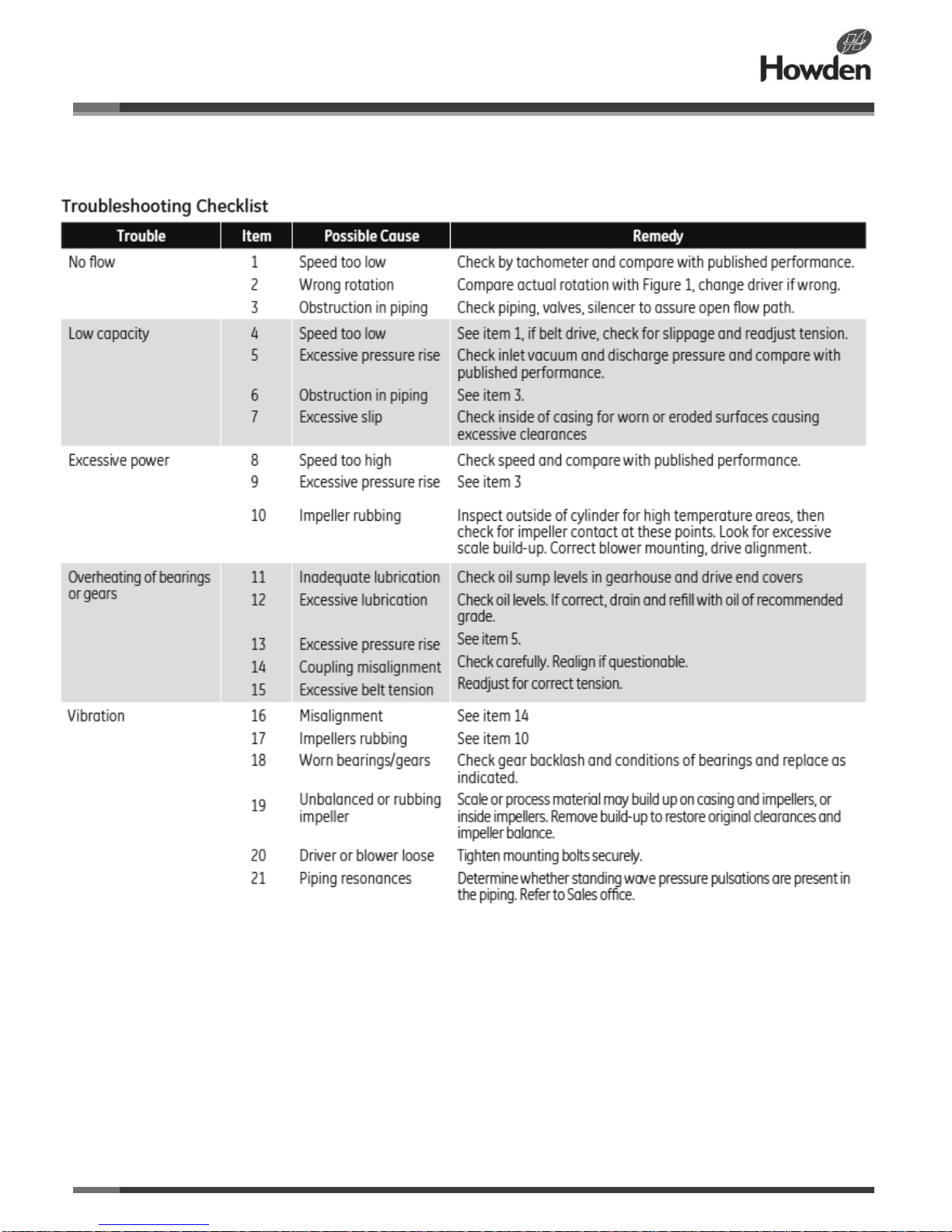
If trouble appears, refer to the TROUBLESHOOTING
CHECKLIST for suggested remedies. The blower
should now be ready for continuous duty under full load.
During the first several days, periodically verify that all
conditions remain reasonably steady and within limits.
These checks may be especially important if the unit is
part of a process system where conditions may vary. At
the first opportunity, stop the blower and clean or
remove the temporary inlet protective screen. If no
appreciable amount of debris has collected, the screen
may be removed. See comments under
INSTALLATION. Also, verify levelling, coupling
alignment or belt tension, and anchor bolt tightness.
If operating experience indicates that the blower’s
capacity is a little too high for the actual requirements, a
small excess may be blown off continuously through the
manual unloading or vent valve. Never rely on the
pressure relief valve as an automatic vent because it
may cause the discharge pressure to become
excessive, and can also result in valve failure. If the
blower capacity is too low, refer to the
TROUBLESHOOTING CHECKLIST before contacting
the nearest Howden Roots sales office for
recommendations.
Page 14

ILRB-3000 GEA20261 RAS and RAS-J WHISPAIR Blowers
Page 14 of 33
Safety Precautions
When working with any of the equipment mentioned in this
manual, it is important to observe safety precautions to
reduce chance of injury. The following safety
considerations are particularly important:
• The blower casing and associated piping or accessories
may become hot enough to cause major skin burns on
contact.
• Internal and external rotating parts of the blower and
driving equipment can produce serious physical injuries. Do
not reach into any opening in the blower while it is
operating, or while subject to accidental starting. Cover
external moving parts with adequate guards.
• Disconnect power before doing any work, and do not
bypass or render inoperable any safety or protective
devices.
• If the blower is operated while the piping is disconnected,
place a strong, coarse screen over the inlet and avoid
standing in the discharge air stream.
• Stay clear of open inlet piping (suction area) of pressure
blowers, and the open discharge blast from vacuum
blowers.
• Stay clear of the blast from pressure relief valves and the
suction area of vacuum relief valves.
• Avoid extended exposure in close proximity to machinery
that exceeds safe noise levels.
• Use proper care and good procedures in handling, lifting,
installing, operating, and maintaining the equipment.
• Use proper care and good procedures in handling, lifting,
installing, operating, and maintaining the equipment.
• Casing pressure must not exceed 25 PSI (172 kPa)
gauge. Do not pressurize vented cavities from an external
source. Do not restrict the vents.
• Do not use air blowers on explosive or hazardous gases.
• Other potential hazards to safety may be associated with
operating this equipment. All personnel working in or
passing through the area should be warned by signs and
trained to exercise adequate general safety precautions.
Preventive Maintenance
Daily
• Record the following:
− Lube oil pressure (if applicable)
− Lube oil temperature (if applicable)
− Blower inlet temperature
− Blower inlet pressure
− Blower discharge temperature
− Blower discharge pressure or differential pressure
− Motor amperage
− Motor voltage, if available
− Motor stator temperature, if available
− Motor bearing temperature, if available
• Observe any abnormalities, such as burned paint,
unusual noises, vibration, strange odours, oil leaks, and so
on.
• Review log sheets to determine if there are any changes
from previous readings. It is very important to look for any
changes or trends that might indicate pending problems.
• Check oil levels.
• Record hour meter readings.
Monthly
Record bearing housing vibration levels at each bearing in
the horizontal, vertical, and axial planes. Use velocity
(inches per second) measurements and note any changes
from previous readings. Take a complete vibration
signature (amplitude versus frequency) if any trends are
noted. It may be helpful to keep a chart noting monthly
readings.
Quarterly
• Sample the lube oil
• Change the oil if the following values are exceeded:
− Water 100 PPM maximum
− Metals 200 PPM maximum
− Acid 5.0 to 7.5 mg/KOH/g maximum
• Increase the sample frequency if any of the above values
show a 20 to 25 percent increase over the last sample.
• Flush all oil reservoirs before filling with clean oil. Annually
• Remove an inlet expansion joint, inspect the impellers,
measure impeller clearances, and note wear patterns.
Page 15

ILRB-3000 GEA20261 RAS and RAS-J WHISPAIR Blowers
Page 15 of 33
• Check the coupling alignment, inspect the coupling for
wear, and repack with fresh grease.
• Inspect oil cooler tubes, as applicable.
• Check all protective switches for proper set points and
operation.
• Check v-belt drive condition and tension.
Note: A preventative maintenance schedule should be
established for drivers and all accessories in accordance
with the applicable manufacturer’s recommendation.
Page 16
ILRB-3000 GEA20261 RAS and RAS-J WHISPAIR Blowers
Page 16 of 33
Page 17

ILRB-3000 GEA20261 RAS and RAS-J WHISPAIR Blowers
Page 17 of 33
Rotary Lobe Blower Vibrations
Blower vibration levels should be monitored on a regular basis. Take measurements at the bearing locations on the housings
and refer to the chart below for guidelines on assessing the vibration severity of a rotary lobe blower rigidly mounted on a stiff
foundation. When vibration measurements indicate that a review is required, the installation should be fully evaluated to
determine and resolve the causes of vibration.
In addition, vibration level trends should be observed for progressive or sudden changes. If a change occurs, the cause should
be determined through spectral analysis.
Blower vibrations are transmitted into the motor, speed reducer, and other system components. Make sure to obtain the
allowable vibration levels of all accessories from the associated vendors.
Note: Rotary lobe blower vibrations are measured in inches per second. The measurement of spike energy is not recommended
for judging blower condition because the rotary lobe blower has inherent impacting bearing loads.
The following items generate vibrations in rotary lobe blowers:
• Inherent rotary lobe blower characteristics can lead to vibrations:
− Impacting bearing loads excite component/ system natural frequencies.
− Pressure pulsations set off vibrations at four times the running speed (RPM).
• Very close clearances between the impellers and the housing can result in vibrations set off by impeller contact:
− Impeller to impeller frontal lobe contact. If contact is between only one set of lobes, the vibration frequency is one times the
RPM. If both sets of lobes contact, the vibration frequency is two times the RPM.
− Impeller to cylinder contact. The vibration frequency depends on the number of impeller tips contacting the cylinder and can
range from one to four times the RPM.
− Impeller to head plate contact. The vibration frequency is erratic and unsteady.
• Damaged gears generate vibrations at mesh frequency (number of teeth times RPM).
• Damaged bearings generate vibrations at ball pass frequency, fundamental train frequency, and ball spin frequency.
• Rotor unbalance and a bent shaft generate vibrations at one times RPM.
• Blower/driver coupling misalignment generates vibrations at one times RPM and two times RPM.
• Acoustic resonance in the blower inlet/discharge piping generates vibrations at four times RPM.
• Operation of a rotary lobe blower at or near system torsionals may cause impeller lobe contact and increase vibrations.
• If external piping is not properly isolated it will transmit vibrations into the blower.
• The foundation design and mounting method considerably affect blower vibrations.
Maintenance/Replacement
A consistent program of inspection and maintenance is the most reliable way to reduce the need for costly blower repairs. To
help establish a regular maintenance schedule, keep a simple record of procedures and dates. While operating the unit within
its specified rating limits is the best way to help ensure a satisfactory service life, the following basic ongoing service needs
should also be performed:
• Lubrication
• Cleaning
• Checking for hot spots
• Checking for increases or changes in vibration
• Frequently observing inlet and discharge pressures to ensure that blower ratings are not exceeded In a properly installed and
operated blower, there is no moving contact between the two impellers, or between the impellers and cylinder or headplates.
Wear is confined to the timing gears, the bearings that support and locate the shafts, and the shaft oil seals. When properly
lubricated with clean oil of the correct grade, only normal wear should occur. Shaft seals (lip type or rotating mechanical type),
Page 18
ILRB-3000 GEA20261 RAS and RAS-J WHISPAIR Blowers
Page 18 of 33
are subject to deterioration as well as wear and may require replacement at varying periods. O-rings should be replaced at each
disassembly.
Troubleshooting and Repairs
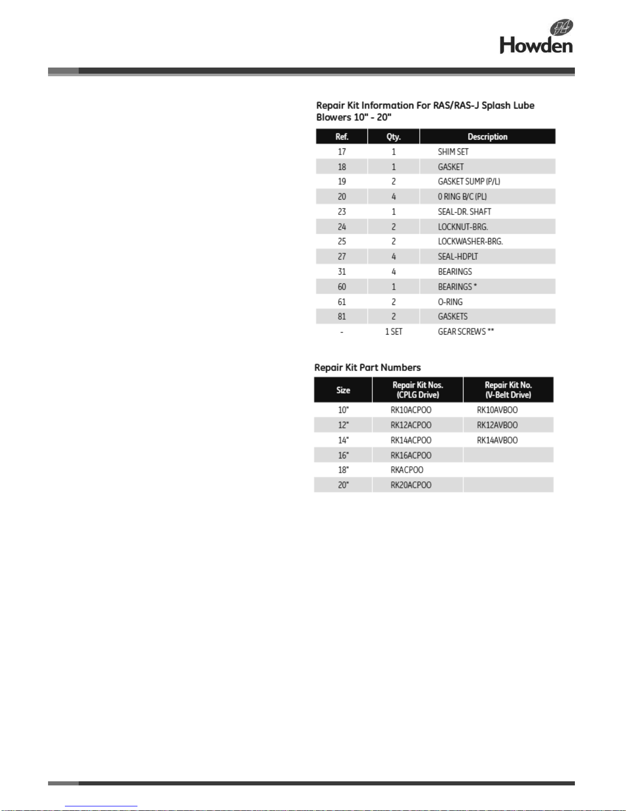
Refer to the TROUBLESHOOTING CHECKLIST for a wide range of causes and solutions for operating troubles. Suggested
remedies can typically be performed by qualified mechanics, using procedures detailed in this manual.
Major repairs not covered in this manual are considered beyond the scope of maintenance, and should be performed by
Howden Roots personnel. Refer to the nearest Howden Roots sales office as listed on the last page of this manual. Do not
attempt to
repair failures covered by warranty, unless specific approval has been obtained through a Howden Roots sales office
before starting the work. Unauthorized disassembly within the warranty period may void the warranty.
When repairs involve parts replacement, factory parts should be used to ensure fit and suitability. Keeping spare parts on hand
can help reduce delays associated with repairs. Remember to supply all information from the blower nameplate when ordering
parts.
Repair and Adjustment Procedures - Some operations involve extra care and a degree of precision work. This is especially true
of the procedures for timing impellers and handling bearings. Experience indicates that a high percentage of bearing failure is
caused by dirt contamination before or during assembly. Therefore, clean the work area before starting disassembly, and
protect new or reusable parts as work progresses.
The following detailed work procedures describe repairs and adjustments that can typically be handled successfully at the
installation site. While reading the instructions, refer to the item numbers (shown in parentheses) on the related sectional
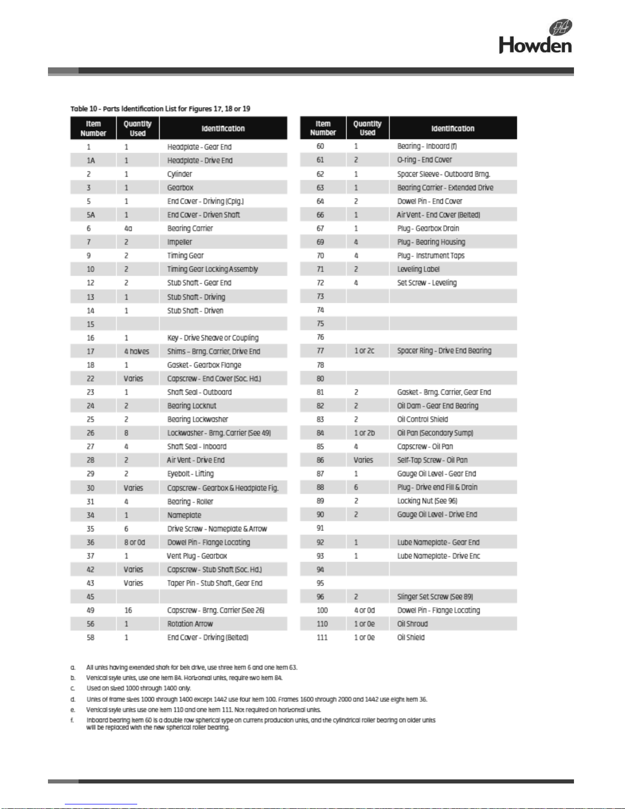
assembly drawings and in Table 9.
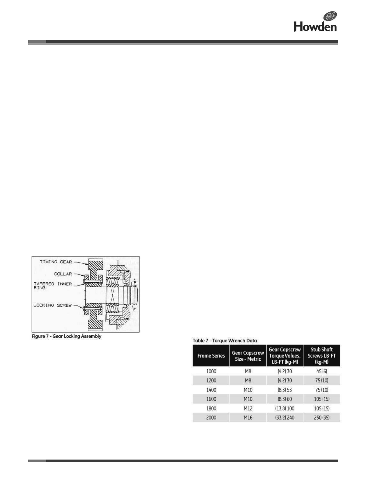
A - Removing Gears with Gear Locking Assemblies
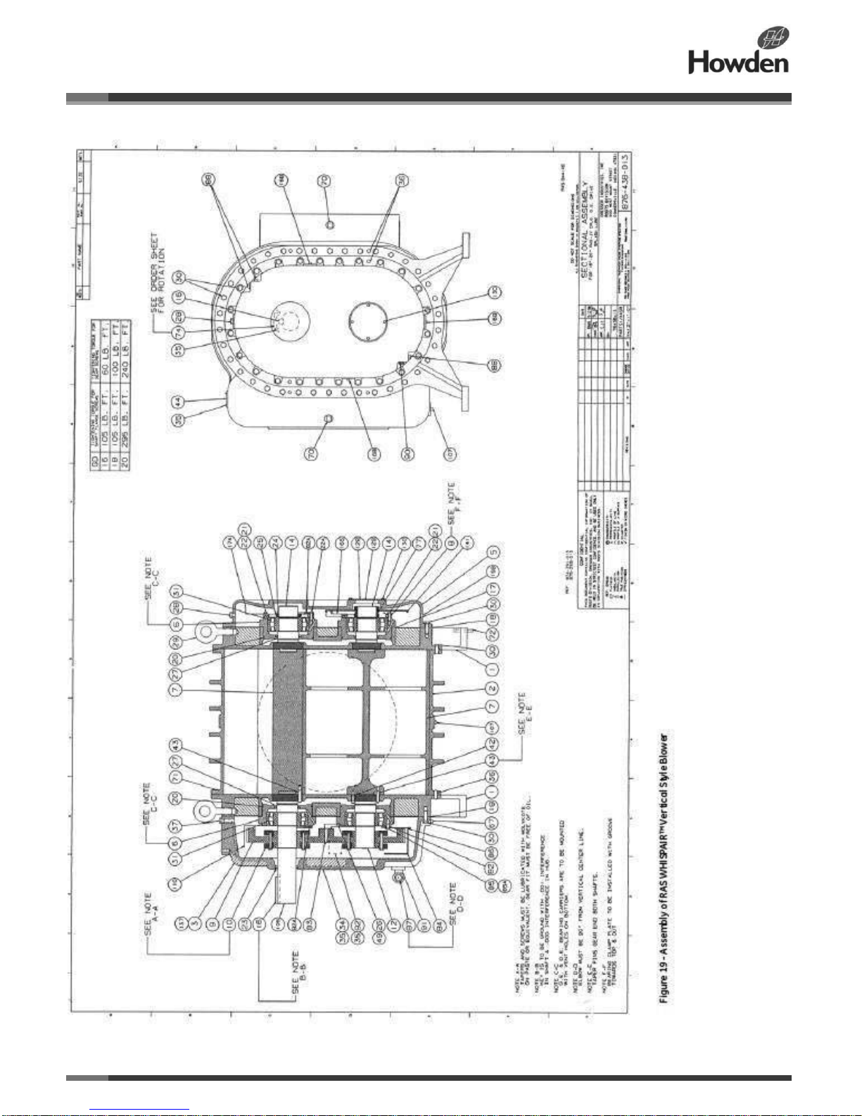
1. Drain the oil using the plug (67) near the bottom of the gearbox (3).
2. Loosen the cap screws (30) that attach the gearbox to the headplate.
3. Attach the lifting device to support the gearbox and remove the cap screws. Move the gearbox out of the way.
4. Make match marks on the gears so that they can be returned
to the same shafts in the same position.
5. Gradually and evenly release the gear locking assembly cap
screws all around. Initially, each screw should be released about
a quarter of a turn to prevent tilting and jamming of collars.
Loosen the locking assembly so that both collars are loose on
the tapered inner rings. To loosen the back collar, you may need
to tap on the locking screws. To loosen the front collar, you may
need to use wedges between the collar and the gear web.
Warning: Do not remove the locking screws completely or the collar may spring off and cause injury.
6. Pull the gears off the shafts using the two puller holes in the gear (see Table 6 for size information).
Page 19
ILRB-3000 GEA20261 RAS and RAS-J WHISPAIR Blowers
Page 19 of 33
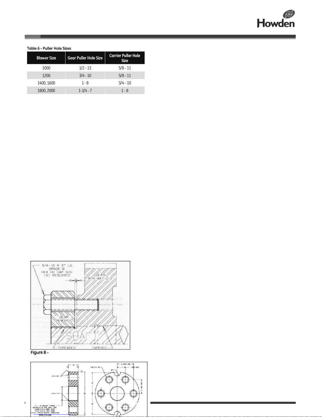
B - Installing Gears with Gear Locking Assemblies
1. Apply Neverseez paste on the gear locking device screw threads, under the screw heads, on the tapered rings, on the collar
tapers, and on the gear hub outside diameters.
2. Slide each tapered ring collar and the web clearance holes and screw them loosely into the opposite collar. Note: Do not
tighten the screws at this time.
3. Degrease the gear hub bore and shaft. The gear fit must be free of lubricant.
4. Install two 12-inch-long threaded rods (see Table 5 for size information) in the bearing carrier puller holes. Line up the gear
puller holes with the rods and use the proper nuts on the guide rods to push the gears on flush with the shaft end.
Make sure that the gear match marks line up. Snug up any three or four equally spaced locking screws.
5. Set the impeller timing as described under Step 4 of Operation C.7. Once satisfactory timing is achieved, use a calibrated
torque wrench to tighten the locking screws (values noted in Table 7). Tighten all of the locking screws gradually in either a
clockwise or counter-clockwise sequence, not in a diametrically opposite sequence. Tighten the screws half a turn at a time.
Check that the screws cannot be turned any more by applying the specified torque.
Removing 10” Taper Bore Gears
1. Remove the gear nut.
2. Install Gear Remover within 1/8 inch of the gear face. Note: This gap is necessary to unseat the gear from the shaft taper.
3. Apply Neverseez on 3/4-10X3” long, grade 8 cap screw threads and under the hex heads.
4. Install cap screws through the gear remover holes into the gear
puller holes. Tighten the cap screws a quarter turn at a time in
either a clockwise or counter-clockwise sequence, not a
diametrically opposite sequence, until the gear is unseated from
the taper.
If the gear does not come off using the above procedure, use the
hydraulic assist feature provided in the gear in addition to the
above steps. A hydraulic pump capable of generating about
20,000 PSI pressure is required. Make sure that all of the tubing
and fittings are good for 40,000 PSI. The gear connections are
1/4-inch NPT. Hook the pump up to the bottom connection.
Leave the top hole open. Crank the pump until some oil comes
through the open hole bleeding all air out. Close the top hole
with a 1/4-inch NPT solid steel plug. Crank the pump up until
the gear comes off. Do not exceed 20,000 PSI oil pressure. If
you are not sure how to use the hydraulic removal system,
contact the factory.
Installing 10” Taper Bore Gears
1. Block the impellers inside the blower using wooden
blocks/wedges.
Page 20

ILRB-3000 GEA20261 RAS and RAS-J WHISPAIR Blowers
Page 20 of 33
2. Degrease the gear bore and shaft taper. Note: All surfaces must be free of oil.
3. Screw the inside ring onto the shaft and snug it up against the gear by hand.
4. Slide the outside ring onto the inside ring.
5. Apply Neverseez on the threads and under the head of the installation cap screws. Finger tighten the cap screws.
6. Install the indicator on the gear outside face for measuring the gear axial movement.
7. Tighten each screw a quarter turn at a time in either a clockwise or counter-clockwise sequence, not a diametrically opposite
sequence, until the outer ring is solid against the inside ring. Note: The gear should move .065 to .075 inches.
8. Loosen up the installation cap screws and remove the gear installation tooling.
9. Install the gear locknut and tighten the nut with a spanner wrench.
Page 21
ILRB-3000 GEA20261 RAS and RAS-J WHISPAIR Blowers
Page 21 of 33
C - Timing the Impellers
1. Disconnect the piping at both the inlet and discharge flanges
of the machine. Note: Move the pipe flanges at least far enough
away for easy insertion of an arm into the openings.
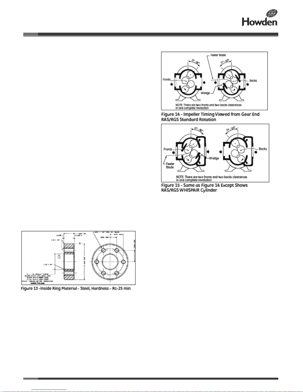
2. Use a set of feeler gauges with blades about 12 inches (300
mm) long for measuring clearances between the impeller lobes.
These clearances are identified as “front” and “back”, and are
measured with the impellers in the positions shown in Figures 13
and 14. The drive shaft rotation indicated is counter-clockwise.
For opposite rotation, impeller positions are reversed from those
shown in Figures 13 and 14, and the front and back
identifications are interchanged. Fronts may be defined as the
lobes that tend to contact during rotation because of pressure
load and gear tooth wear; conversely, backs are the surfaces
that tend to separate.
3. Determine and record the total lobe clearance by adding the
front and back clearance measurements. It is normally
satisfactory to take measurements at the mid-point of the
impeller length. Place a wedge between the gear teeth to prevent
the impellers from shifting during the measurement, making sure
that any gear tooth clearance is always taken up in the same
direction. Note: There are two front and two back clearance
positions in one complete revolution. Use the minimum clearance
value found along the length of impeller for fronts and backs
throughout a 90-degree rotation.
4. Loosen the screws on one gear (make sure the collars are
loose) to permit slight adjustments of position relative to its impeller, and set the impeller “front” clearance so that it is two-thirds
of the total clearance found in Step 3. Make sure that any backlash in the gears is taken up in the direction of rotation with the
lower gear driving.
5. Tighten all screws as described in Step 7 of Operation B, and recheck the front and back clearances.
D - Removing Bearings and/or Seals
1. Dismantle as described in Operation A.
2. Remove the gear end bearing carriers (6). Bearings and shaft seals will come out with the carriers. Discard the O-rings (20).
Impellers are now supported by the labyrinth seals in headplate holes.
3. Dismount the drive and remove the drive end cover (5) and/or (58), using care with the seal (23).
4. Use a spanner wrench to remove the bearing locknuts (24) and lockwashers (25).
5. Remove the bearing clamp plates (8).
6. Pull the drive end bearing carriers with bearings and seals as on the gear end. Keep the shims (17) under the flanges in order
and identify them so they can be replaced in the same positions
Page 22
ILRB-3000 GEA20261 RAS and RAS-J WHISPAIR Blowers
Page 22 of 33
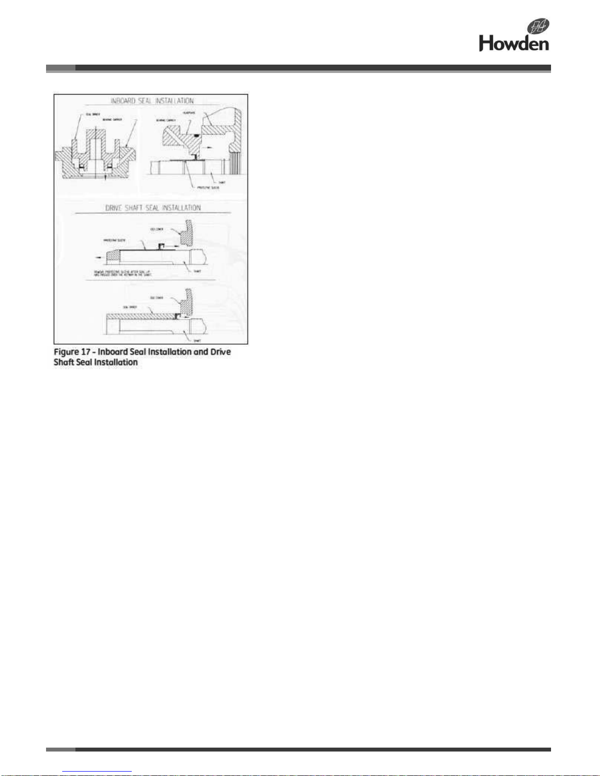
E - Replacing Lip Seals (RAS/RAS WHISPAIR)
1. Check the shafts for a surface finish of 10-16 micro inches (.3 to .4 micrometers) root mean square (RMS) in the seal contact
area. Also ensure that they are in good condition at the bearing locations. Carefully remove any burrs or sharp corners, but do
no attempt to refinish them.
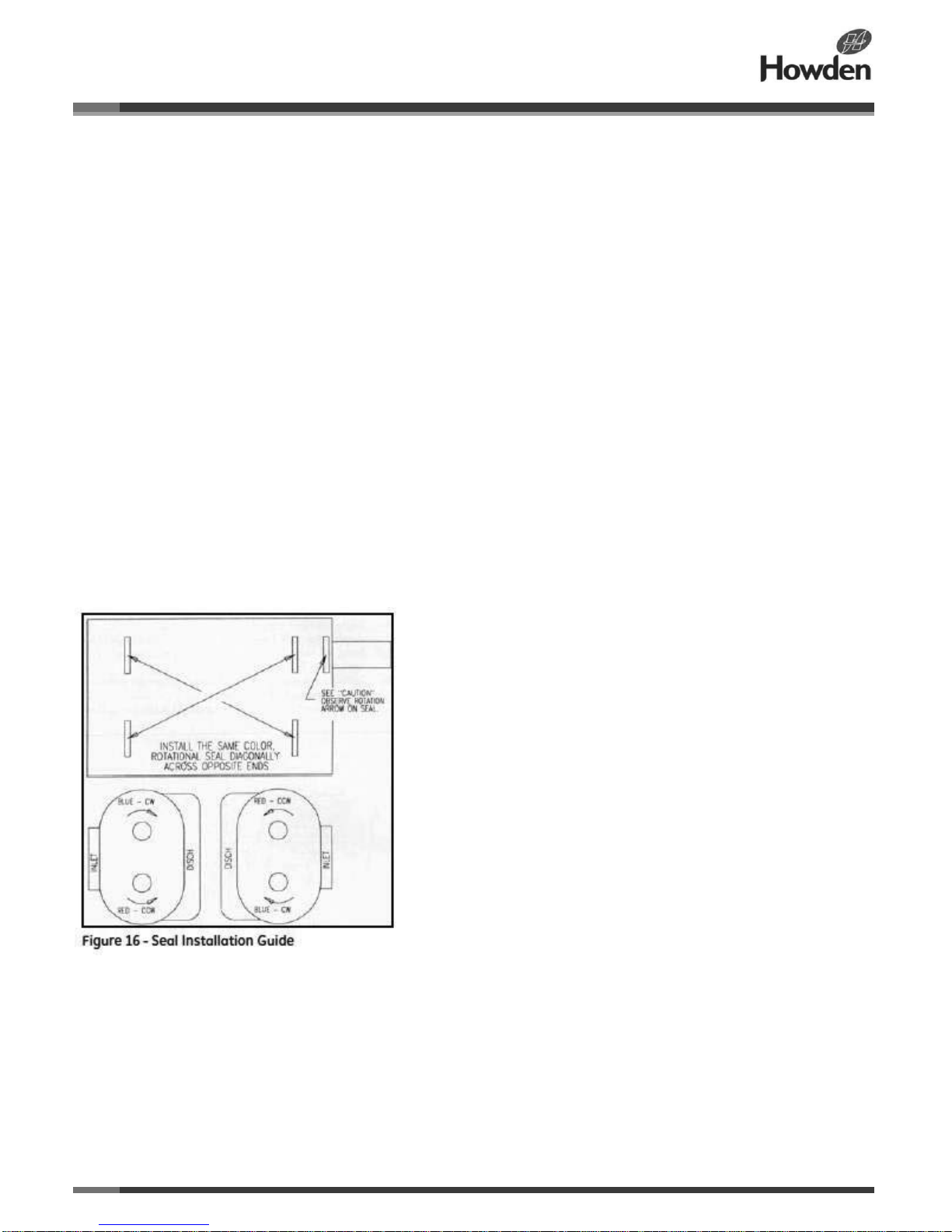
The seals are “Directional, Hydrodynamic,” which means that proper sealing is completely dependent on the direction of the
shaft rotation. In each seal kit, there are:
• (2) Clockwise (CW) “blue coated” seals for inboard seal replacement
• (2) Counter-clockwise (CCW) “red coated” seals for inboard seal replacement
• Reversible (CW/CCW) “green coated” seal for drive shaft seal replacement
• Protective sleeve tool (inboard seals)
• Protective sleeve tool (drive shaft seal)
Warning: For seals to perform properly:
• Use careful handling procedures to avoid damaging the seals during installation. Use the installation sleeves provided in the
kit as described in Operation F below. Seal lips are not very flexible and will tear or become damaged if not installed properly.
• Clean the shaft surface and make sure it is free of scratches with a finish between 10 to 20 RMS.
• Keep the seals on the shipping rings until the time of installation. Otherwise the seal lips will deform over time.
Note: Proper sealing for shafts that have been repaired with a “speedi-sleeve” depends on the quality of the “speedi-sleeve” and
its installation.
2. Finish the assembly as outlined below.
Page 23
ILRB-3000 GEA20261 RAS and RAS-J WHISPAIR Blowers
Page 23 of 33
Page 24

ILRB-3000 GEA20261 RAS and RAS-J WHISPAIR Blowers
Page 24 of 33
F - Performing the Final Assembly
1. Install all of the bearings, making sure they are tight against the respective shaft shoulders. Work on the gear end bearings
first and press them into place using a suitable length of tubing in contact only with the inner races. The impellers will be driven
against the opposite headplate. Remove the shims (17) from behind both drive end bearing carrier flanges and press the
bearings at this end into place against the shaft shoulders.
On a belt-drive unit with an extended shaft, use the spacer sleeve (62) to push the inboard bearing (60) into its final position.
There is no shaft shoulder behind this bearing, but there is a stop for the sleeve. Make sure that the inner race flange of bearing
(60) is facing outboard.
2. Install the bearing lockwasher (25) and locknuts (24) on each shaft and tighten the nuts with a spanner wrench. Lock the nuts
by bending a tab on each washer into a slot in the nut.
3. Install new or original gears and set the impellers as described in Operation B.
4. Place the bearing clamp plate (8) over the main bearing (31) and tighten all of the screws. For an extended type drive shaft,
the end cover (58) serves as the clamp plate but cannot be installed until later.
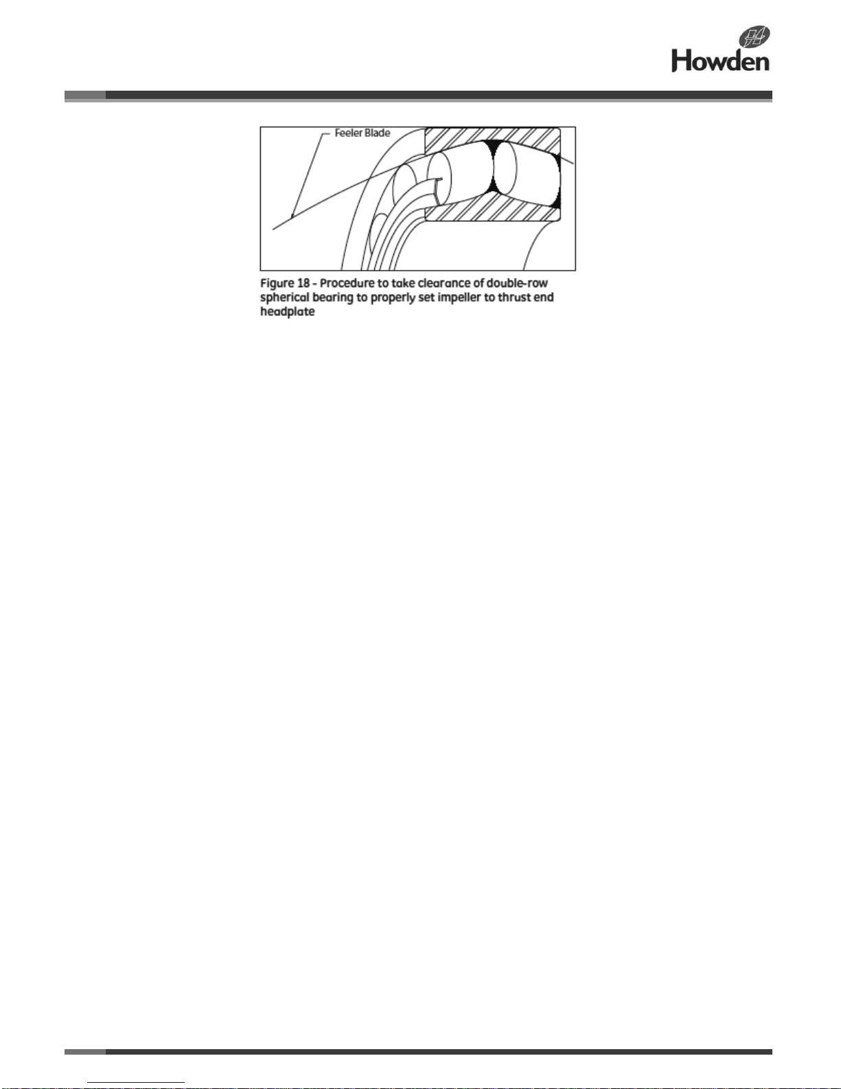
5. Using 1/2-inch (13mm) feeler gauges, determine the maximum clearance between the outer race and one of the rollers near
the top for each of the drive end bearings (31). Obtain pieces of brass shim stock that are as thick as the clearances measured,
about ¾ inches (19mm) wide, and long enough to reach completely through the bearings. Push one piece through each
bearing, in the spaces between rollers, then rotate that shaft so that one roller of each row is up on the shim stock. This
removes all clearances, and forces the bearing rollers and races to center as in normal running. Refer to Figure 15.
6. Set the impellers lengthwise in the case using long pieces of shim stock, or feelers, as wedges between the two ends of each
impeller and the headplates. Apply the total end clearance obtained in Step 8 of Operation D to the two ends of each impeller
and the headplates. Place wedges equal to two-thirds of the total end clearance obtained in Step 8 of Operation D at the gear
end and one-third of the total at the drive or thrust end. Bump the shafts to obtain the required impeller positions. Set the drive
end clearance first, after installing an tightening drive shaft end cover (58) if used.
7. With feeler gauges, carefully measure the spaces between the drive end bearing carrier flanges and the headplate face.
Insert shims (17) of the correct thickness to fill these spaces. The original shims should be correct if the bearings and carriers
were returned to the original location.
8. Remove the wedges from the ends of the impellers inside the casing.
9. Tighten all of the bearing carrier flange screws.
10. Recheck the impeller end clearances for proper values (as noted in the tables), then remove the brass shim stock from both
bearings (31).
11. Check the front and back clearances of the impeller lobes as outlined in Operation C, and reset the timing if not correct.
12. Reassemble the unit, starting by installing the main end cover (5) and proceeding in reverse order through Operation A from
Step 5. Be careful with the lip seal (23) or new O-ring (59) in the end cover (5).
13. Check the work area to make sure no parts have been left out in assembly.
14. Turn the drive shaft over several times by hand as a final check for impeller contact or case rubs.
15. Reinstall the coupling or belt sheave. Check the alignment with the driver and reconnect all external piping.
16. Start and operate the unit for a reasonable period in the manner outlined for initial starting under OPERATION.
Page 25
ILRB-3000 GEA20261 RAS and RAS-J WHISPAIR Blowers
Page 25 of 33
Page 26
ILRB-3000 GEA20261 RAS and RAS-J WHISPAIR Blowers
Page 26 of 33
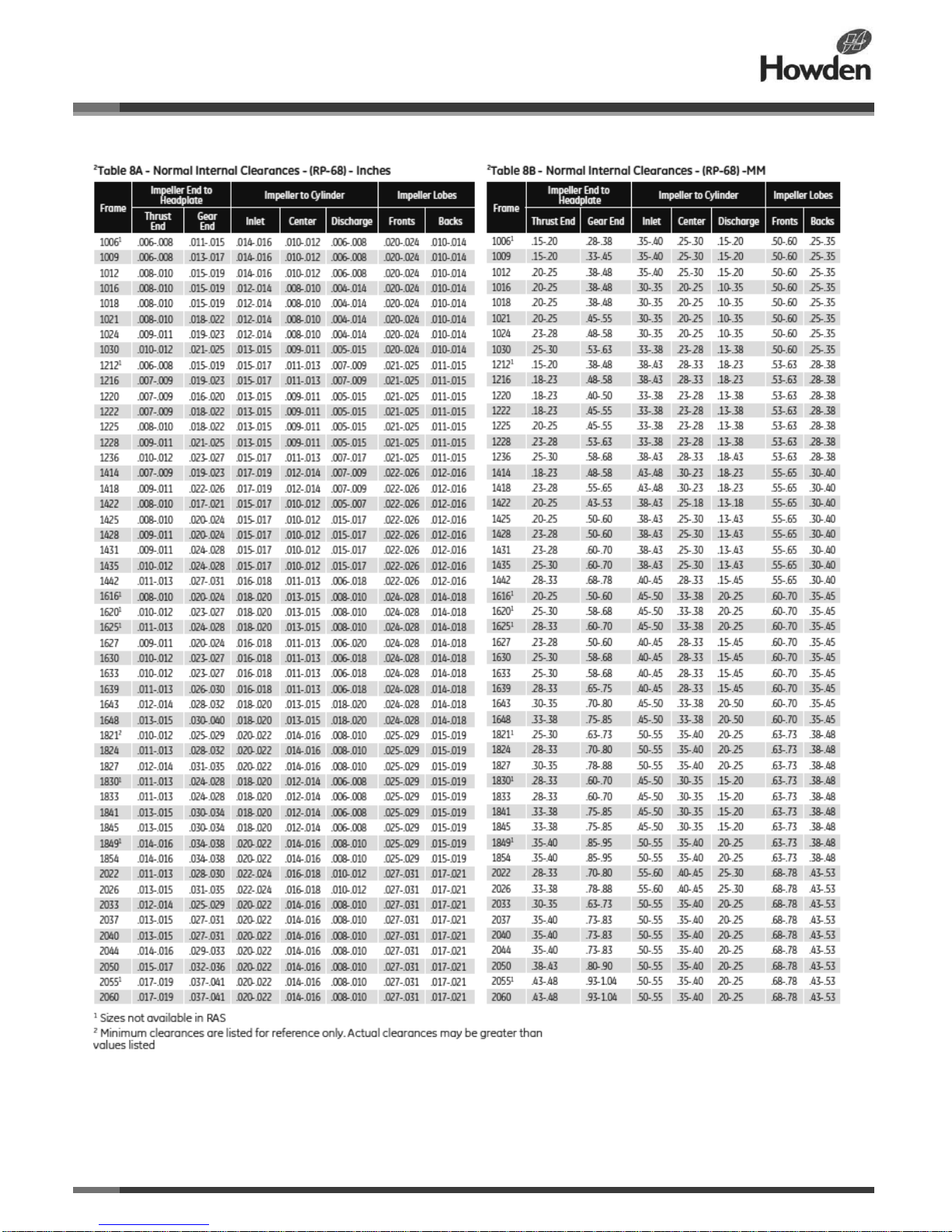
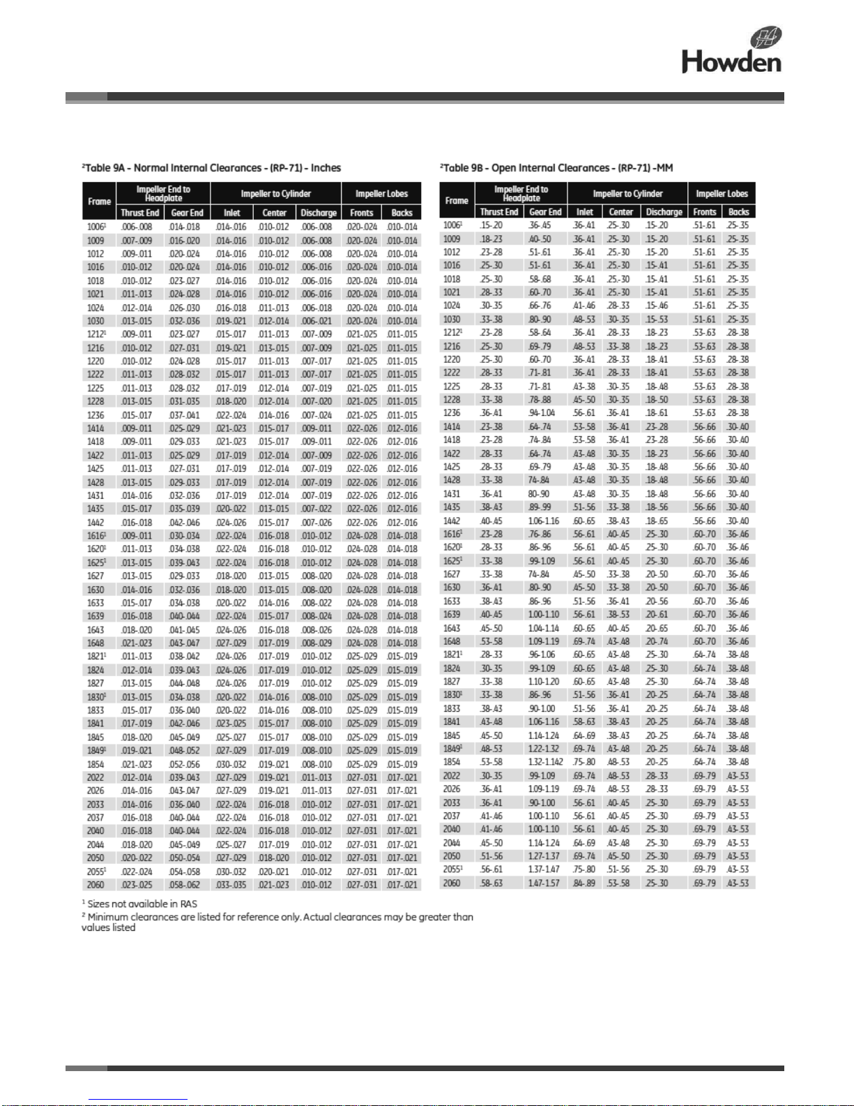
Impeller Clearances
The instructions related to impeller clearances described in
Operation C and D do not include the amount of clearance to
be expected. For blowers in good condition this information is
not essential in field service work. However, if a situation
occurs in which it would be helpful to compare existing
clearance to original values, Table 8 or 9 lists the ranges of
values used in original factory assembly. Clearances may
change in service, but they should never be less than the
minimum values listed.
Only well qualified personnel should attempt to measure
clearances for comparison with this data.
Page 27
ILRB-3000 GEA20261 RAS and RAS-J WHISPAIR Blowers
Page 27 of 33
Page 28
ILRB-3000 GEA20261 RAS and RAS-J WHISPAIR Blowers
Page 28 of 33
Page 29
ILRB-3000 GEA20261 RAS and RAS-J WHISPAIR Blowers
Page 29 of 33
Page 30
ILRB-3000 GEA20261 RAS and RAS-J WHISPAIR Blowers
Page 30 of 33
Page 31
ILRB-3000 GEA20261 RAS and RAS-J WHISPAIR Blowers
Page 31 of 33
Page 32
ILRB-3000 GEA20261 RAS and RAS-J WHISPAIR Blowers
Page 32 of 33
Page 33
©Howden Group Limited. All rights reserved. 2015
Howden Roots
900 West Mount Street
Connersville,Indiana 47331
USA
www.howden.com
At the heart of your operations
Howden people live to improve our products and services and for over
150 years our world has revolved around our customers. This dedication
means our air and gas handling equipment adds maximum value to your
operations. We have innovation in our hearts and every day we focus on
providing you with the best solutions for your vital operations.
 Loading...