

Page 1
www.howden.com
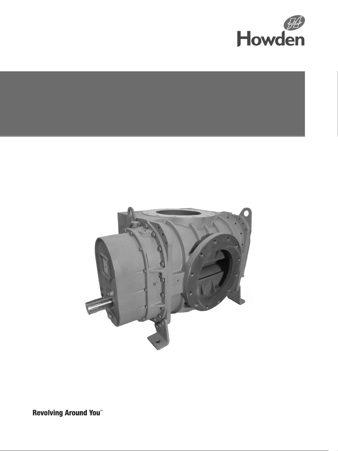
Roots
TM
827 DVJ gear end drive
blower
Installation Operation & Maintenance Manual
Page 2

Contents
Information Summary ������������������������������������������������2
Warranty and Limitation of Liability �����������������������������2
Safety Precautions �����������������������������������������������������3
Installation ������������������������������������������������������������� 3-5
Lubrication
Operation �������������������������������������������������������������� 7-8
Vibration Assessment Criteria ������������������������������������8
Troubleshooting �������������������������������������������������������11
����������������������������������������������������������������7
Do These Things To Get The Most From Your ROOTS™ Blower
• Check shipment for damage� If found, file claim
with carrier and notify Howden�
• Unpack shipment carefully and check contents
against packing List� Notify Howden if a shortage
appears�
• Store in a clean, dry location until ready for
installation� Lift by methods discussed under
installation to avoid straining or distorting the
equipment� Keep covers on all openings� Protect
against weather and corrosion if outdoor storage
is necessary�
• Read LIMITATIONS and INSTALLATION sections
in this manual and complete the installation�
• Provide for adequate safeguards against
accidents to persons working on or near the
equipment during both installation and operation�
SEE SAFETY PRECAUTIONS�
• Install all equipment correctly� Foundation design
must be adequate and piping carefully done�
Use recommended accessories for operating
protection�
• Make sure both driving and driven equipment
is correctly lubricated before start-up� See
LUBRICATION�
• Read starting checkpoints under OPERATION�
Run equipment briefly to check for installation
errors and make corrections� Follow with a trial
run under normal operating conditions�
• In event of trouble during installation or operation,
do not attempt repairs of Roots equipment� Notify
nearest Howden Sales Office giving all nameplate
information plus an outline of operating conditions
and a description of the trouble�
• Unauthorized attempts at equipment repair
may void Manufacturer’s warranty� Units out of
warranty may be repaired or adjusted by the
owner� It is recommended that such work be
limited to the operations described this manual,
using Factory Parts� Good inspection and
maintenance practices should reduce the need for
repairs�
Roots products are sold subject to the current General Terms of Sale, ES104 and Warranty Policy
WP-5020.
2
GEA30580_Rev_11.15
Page 3

Foreword
A blower is a precision engineering product with
very fine clearances between the twin impellers and
between the impellers and the casing� As there is no
contact between the moving parts internal lubrication
is unnecessary� This ensures that relatively oil free air
is delivered at all times�
Safety Precautions
For equipment covered specifically or indirectly in
this instruction book, it is important that all personnel
observe safety precautions to minimize the chance
of injury� Among many considerations, the following
should particularly be noted�
• Do not use V-belt drive�
• Blower casing and associated piping or accessories may become hot enough to cause major
skin burns on contact�
• Operate blower only per nameplate ratings and
limits listed in this manual�
• Internal and external rotating parts of the
blower and driving equipment can produce serious
physical injuries� Do not reach into any opening in
the blower while it is operating, or while subject to
accidental starting� Cover external moving parts
with adequate guards�
• Disconnect power per lock out tag out procedure
before doing any work and avoid bypassing or
rendering inoperative any safety or protective
devices�
• If blower is operated with piping disconnected,
Warning
It is essential that anyone involved in the installation and operation of positive displacement air
blowers, must have read and understood these
instructions. There is a risk of damage and injury
resulting from improper handling and operation.
place a course screen over the inlet, jet port and
discharge� Avoid standing in the path of the air
streams� Wear appropriate PPE�
• Stay clear of open piping�
• Stay clear of blast from pressure relief valves and
the suction area of vacuum relief valves�
• Avoid extended exposure in close proximity to
machinery that exceeds safe noise levels�
• Use proper care and good procedures in handling,
lifting, installing, operating and maintaining the
equipment�
• Casing pressure must not exceed 25-PSI (172 kPa)
gauge� Do not pressure vented cavities from an
external source, nor restrict the vents�
• Do not use air blowers on explosive or hazardous
gases or liquids�
• If condensate or water can collect in blower casing,
must drain prior to start�
• Other potential hazards to safety may also be
associated with operation of this equipment� All
personnel working in or passing through the area
should be warned by signs and trained to exercise
adequate general safety precautions�
GEA30580_Rev_11.15
3
Page 4

Installation
Do not V-belt drive the 827 DVJ which is Gear End
driven� The addition of belt forces could cause
undesired and uneven gear contact and damage the
blower�
A temporary cover is installed on one jet port along
with a permanent cover on the other at the factory�
A silencer must be installed in place of the temporary
cover before operating the blower; however, the
permanent cover and silencer locations may be
exchanged if required by the installation�
The permanent cover must be removed, both jet
plenums inspected and cleaned for foreign material,
then the permanent cover and silencer installed in the
desired locations before operating the blower� Full
size jet and discharge silencers are desirable, however
the jet silencer may be reduced one nominal size
providing either the vacuum level less than 18�5 “Hg
or if the operating speed is below 60% of maximum
blower speed� Both jet and discharge silencers may
be reduced one nominal size in applications with
vacuum levels is less than 18�5 “Hg and speed is less
than 60% of maximum blower speed�
Avoid opening blower protective covers until ready to
start installation, as protection will be lost quickly by
evaporation�
If internal protection is required due to rust or
corrosion, removal of the blower from service, or
the internal protection furnished by factory at time
of shipment has been removed do not use a liquid
preservative of any kind on the coated surfaces�
Capsules of vapor inhibitor such as ZeRust VC1-1
may be used internally by sealing all machine openings
with vapor barrier paper or tape�
Blowers in long storage should be not subject to
excessive vibration and the blower drive shaft should
be rotated 3 to 4 revolutions every two weeks� Prior
to start-up, remove flange covers on both inlet and
discharge and inspect internals to insure absence of
rust or debris�
This blower has several coats of a fine-grained, natural
graphite coating applied to the internal surfaces� The
coating is applied after the machine’s internal clearances and impeller timing are established� The effect
of coating is to close up internal clearances, decrease
slip, and increase flow and efficiency at any given
speed� Exhaust air may carry some coating particles�
Blowers with internal abradable coating are for use
with clean, dry air only�
After coating, it is not practical to try to measure
clearances involving these surfaces before or after
running the blower� After coating and before running
some coated surfaces may even be touching� After
running the coated surfaces may have abraded areas
and scratches, due to run-in contact between the
surfaces�
Do not attempt to measure clearances involving
coated surfaces as a basis of setting impeller in relation to the cylinder bore, head plates, or each other
(fronts and backs)� Clearance settings can be made
accurately only with uncoated parts�
Where internal inspection indicates a need for cleaning
coated surfaces of dirt, dust, etc�, wipe clean only
with a clean dry rag� Do not use a solvent or cleaner
of any kind or allow solvent or cleaner to reach these
surfaces while cleaning uncoated surfaces�
Cleaning, coating & curing procedure for applying
abradable coating
General: These procedures are for coating new
uncoated repair parts, spot repair of coating, or
renewal� If setting clearances and timing are involved,
this should be done before the new parts are coated�
Subsequent cleaning and coating may involve at
least partial disassembly for proper cleaning without
damaging the coating of other original parts still
coated, and to apply coating properly�
Normally, for new uncoated surfaces, three coats are
applied and each coat must cure properly�
Cleaning before coating
For new uncoated surfaces, apply cleaner with a
clean, “soaked” rag� Apply the cleaner liberally, allow
to set for a minute or two and wipe off� Avoid cleaning
surfaces not to be coated�
Spot repair to be done only with a clean dry rag�
Preparation and coating
Please follow the directions on the aerosol graphite
lubricant container pertaining to preparation, application, ventilation, and inflammability� Typically, one
coat is applied, but when multiple coats are necessary
each coat must be completely cured per the procedure described below before the next application�
Each layer of coating should be applied as evenly as
possible� The best distance from the spray nozzle to
the surface should be 8 to 12 inches� Try to maintain
this distance wherever space conditions allow�”
Curing procedure
Note that coated parts may feel dry or “tack free” after
few minutes, but the coat will not have the proper cure
that is required�
4
GEA30580_Rev_11.15
Page 5

“Two alternative curing methods are acceptable� Let
set for 1-1/2 hours minimum at room temperature
≥ 70°F or if coating is applied below 70°F, allow to
cure overnight in shop ambient temperatures (not
warehouse or outdoors)�”
Check for rotation
Complete blower build if not already assembled� Turn
over drive shaft by hand until the rotation is free� Do
not try to free up the blower by coupled or belted
drive, and do not try to spin the rotors with shop air�
Do not attempt to use any kind of solvent or cleaner
to partially remove coating, as this could ruin all the
coating�
Complete removal of coating
This is for complete removal (to bare metal) of coating
and may require some blower disassembly (depending on blower size and accessibility) for access to the
coated parts and any overspray� Apply removal fluid
liberally with a clean “soaked” rag� Vigorously rubbing
with the rag and scraping of the softened coating is
required to clean the surfaces down to bare metal�
The amount of effort required will vary depending upon
the solvent used� Protect uncoated surfaces from rust�
Because of the completely enclosed blower design,
location of the installation is generally not a critical
matter� A clean, dry and protected indoor location is
normally give satisfactory service� Important requirements are that the correct grade of lubrication oil be
provided for expected temperatures, for expected
temperatures, and that the blower be located so
that routine checking and servicing can be handled
conveniently after installation� The effect of the location
on driver and accessory equipment must be also be
considered�
Supervision of the installation by a Factory Service
Engineer is not usually required for these blowers�
Workers with experience in installing light-medium
weight machinery should be able to produce satisfactory results� Handling of the equipment needs to be
accomplished with care, and in compliance with safe
practices� Blower mounting must be solid, without
strain or twist, and air piping mjust be clean, accurately
aligned and properly connected�
For handling the blower alone, use lifting lugs bolted
into the top of the headplates� Test them first for
tightness and fractures by tapping with a hammer� In
lifting, keep the direction of cable pull on these bolts as
nearly vertical as possible�
When blower is furnished mounted on a baseplate,
with or without a driver, use of lifting slings passing
under the base flange is required� Arrange these slings
so that no strains are placed on the blower casing,
mounting feet, or on any mounted accessory equipment� DO NOT use the lifting lugs in the top of the
headplates.
Before starting the installation, remove plugs, covers
or seals from blower inlet and discharge connections
and inspect the interior the interior completely for dirt or
foreign material� Anti-rust compound on the connection
flanges and drive shaft extension may also be removed
by this time with solvent� Then cover the flanges again
to keep out dirt until ready to connect the air piping�
The corrosion inhibitor used will vaporize and disappear
during operation�
Care, plus consideration of all possible problems, will
pay dividends when arranging the blower mounting�
This is especially true when the blower is a “bare” unit,
furnished without a baseplate� The convenient procedure may be to mount such a unit directly on a floor or
small concrete pad but this generally produces the least
satisfactory results� It causes the most problems in
leveling and alignment�
Direct use of structural framing members is also not a
recommended mounting� If unavoidable, the members
must be rigidly reinforced when part of a building,
and spring type mountings should not be use� Noise
transmission can usually be reduced by use of a cork
insulating pad 1 to 2 inches (35 to 50 mm) thick� The
pad should be supported by a full steel plate attached
to the structure, with a rigid concrete slab on top of
the cork to carry the blower and driver�
For a blower without a base, it is recommended that
a well-anchored and carefully leveled steel or cast iron
mounting plate be provided at the installation point�
The plate should be at least 1 inch (925 mm) thick,
with its tip surface machined flat, and large enough
to provide leveling areas at one side and one end
after the blower is mounted� It should have properly
sized studs or tapped holes located to match the
blower foot drilling� As an alternative, smaller plates
at each end of the blower may be used� This is more
complicated, usually makes leveling more difficult and
can produce twist or strains in the blower� Use of a
high quality machinist’s level is important�
GEA30580_Rev_11.15
5
Page 6

With the mounting plate in place and leveled set the
blower on it without bolting and check for rocking� If
it is not solid, determine the total thickness of shims
required under one foot to stop the rocking� Place half
of this under each of the diagonally opposite short
feet, and tighten the mounting studs or screws� Rotate
the drive shaft to make sure the impellers still turn
freely� If the blower is to be direct coupled to a driving
motor, consider the height of the motor shaft and the
necessity for it to be aligned very accurately with the
blower shaft� The best arrangement is for the blower
to be bolted directly to the mounting plate while the
driver is on shims of at least 1/8-inch (3 mm) thickness�
This allows adjustment of motor position in final shaft
alignment by varying the shim thickness�
When the blower and driver have been factory
mounted on a common baseplate, the assembly will
have been properly aligned and is to be treated as a
unit for leveling purposes� Satisfactory installation can
be obtained by setting the baseplate on a concrete
slab that is rigid and free of vibration, and leveling the
tops of the base carefully in two directions so that it is
free of twist� The slab must be provided with suitable
anchor bolts� The use of grouting under and partly
inside the base after it has been carefully leveled by
shimming, is recommended�
It is possible for a base-mounted assembly to
become twisted during shipment, thus disturbing
the original alignment� For this reason, make the
following checks after the base has been leveled
and bolted down� Disconnect the drive and rotate the
blower shaft by hand� It should turn freely at all points�
Loosen the blower foot hold-down screws and determine whether all feet are evenly in contact with base� If
not, insert shims as required and again check for free
impeller rotation� Finally, if blower is direct coupled to
the driver, check shaft and coupling alignment carefully
and make any necessary corrections�
When the unit is to be directly coupled to its driver, the
driver RPM must be selected or governed so as not
to exceed the maximum speed rating of the blower�
Refer to LIMITATIONS for allowable speeds for various
blower sizes� A flexible type coupling should always
be used to connect the driver and blower shafts� The
standard unit IS NOT DESIGNED for use for V-Belt
Drive�
Coupling halves must be accurately aligned, and a
sufficient gap between shaft ends provided so that
side strains and end thrust on either shaft are avoided
or minimized This will require considerable care in the
mounting of the driver� The two shafts must be in as
near perfect alignment in all directions as possible, and
the gap must be established with the motor armature
on its electrical center if endplay exists�
The following requirements of a good installation are
recommended� Coupling halves must be fitted to the
two shafts with a line to line through �001 inch interference fit� Coupling halves must be warmed up, so that
only light tapping is required to install them� Maximum
deviation in offset alignment of the shafts should not
exceed �005 inches (�13 mm) total indicator reading,
taken on the two coupling hubs� Maximum deviation
from parallel of the inside coupling faces should not
exceed �001 inches (�03 mm) when checked at six
points around the coupling�
Operating limitations
To establish and maintain continued satisfactory performance, Roots blower must be operated
within certain approved limiting conditions� The
Manufacturer’s warranty is, of course, contingent on
such operation�
The DVJ cannot be used in pressure applications as
the pressure build-up discharges air outward through
the cylinder slots resulting in high loss in blower
efficiency and reduction in discharge flow�
Any unnecessary restrictions of discharge flow or
atmospheric air inlet to the cylinder slots reduces the
cooling air flow and limits blower operation, as the
maximum temperature rise will occur below the normal
limits of vacuum level�
Note: One cylinder jet port must have a full size inlet
silencer with no valve or other restrictions� The other
port must have the metal cover plate installed�
Jet and discharge flow restrictions result in increased
blower temperature rise and should be checked as
a possible cause if internal metal-to-metal contact
occurs� Back pressure limits on discharge and vacuum
limits on jet are shown in Table 1A� No valves should
be used in the jet or discharge pipe�
Some type of protection, such as a filter or screen
(1/4” mesh) is necessary to stop foreign particle entry
through the jet port� Outside installations may also
require some weather protection to prevent the entry of
rain or snow� An elbow or some other configuration is
desirable to assist in keeping the screen clear of foreign
particles and the direct entry of rain or snow�
All recheck points in this manual should be followed
with the following additions:
1� Be certain no rags, bolts, or dirt have been left in
the cylinder slot inlet plenums�
2� No valves should be installed in the jet or discharge
silencer pipe�
6
GEA30580_Rev_11.15
Page 7

The blower is suitable for vacuum operation only�
A water manometer should be used on the jet and
discharge to assure that the maximum pressure drop
has not occurred�
Table 1A
% Max speed
RPM
50%
75% 8�0 8�0
100% 10�0 10�0
NOTE: 827 DVJ maximum operating speed is 2400 RPM.
Maximum vacuum is 27 “Hg and maximum temperature rise is
275°F.
Max jet pressure
limit - IN H20
6�0 6�0
Max discharge
pressure limit - IN
H20
Before connecting PIPING, remove any remaining
anti-rust compound from blower connections� Pipe
used should be no smaller than these connection, and
clean new piping throughout is strongly recommended�
In addition, make sure it is free of dirt, scale, cuttings,
weld beads or foreign materials or any kind� To further
guard against damage to the blower, especially when
an inlet against damage to the blower, especially when
an inlet filter is not used, install a substantial screen of
16 mesh backed with hardware cloth at or near the
inlet and jet port connections�
Make provisions to clean this screen of collected debris
after a few hours operation� It should be removed when
nits usefulness has ended, as the wire will eventually
deteriorate and small pieces going into the blower may
cause serious damage�
Piping flanges MUST meet the blower connections
accurately and squarely� DO NOT attempt to correct
misalignment by springing or cramping the pipe� In
most cases this will distort the blower casing and
cause impeller rubbing� In severe cases it can prevent
operation or result in a broken drive shaft� For similar
reasons, piping should be supported near the blower
to eliminate dead weight strains� Also, if pipe expansion
is likely to occur from temperature change, installation
of flexible connectors or expansion joints is advisable�
Figure 1 represents in diagram form a blower installation with all accessory items that might be required
under various operating conditions� Inlet piping should
be completely free of valves or restrictions�
1
Need for an inlet silencer will depend on blower speed
and pressure, as well as sound-level requirements
in the general surroundings� An inlet filter is normally
recommended, especially in dusty or sandy locations
for blower protection� A discharge silencer is also
normally suggested, even though WHISPAIR™ blowers
operate at generally lower noise levels than conventional lobe-type units� Specific recommendations on
silencing can be obtained from Howden�
After piping is completed, and before applying power,
rotate the drive shaft by hand again� If it does not move
with uniform freedom, look for uneven mounting, piping
strain, or coupling misalignment� DO NOT operate the
blower at this time unless it has been lubricated per
instructions� Read LUBRICATION section�
1
For high altitude applications, inlet relief valve may be required to prevent
blower from overheating�
GEA30580_Rev_11.15
7
Page 8
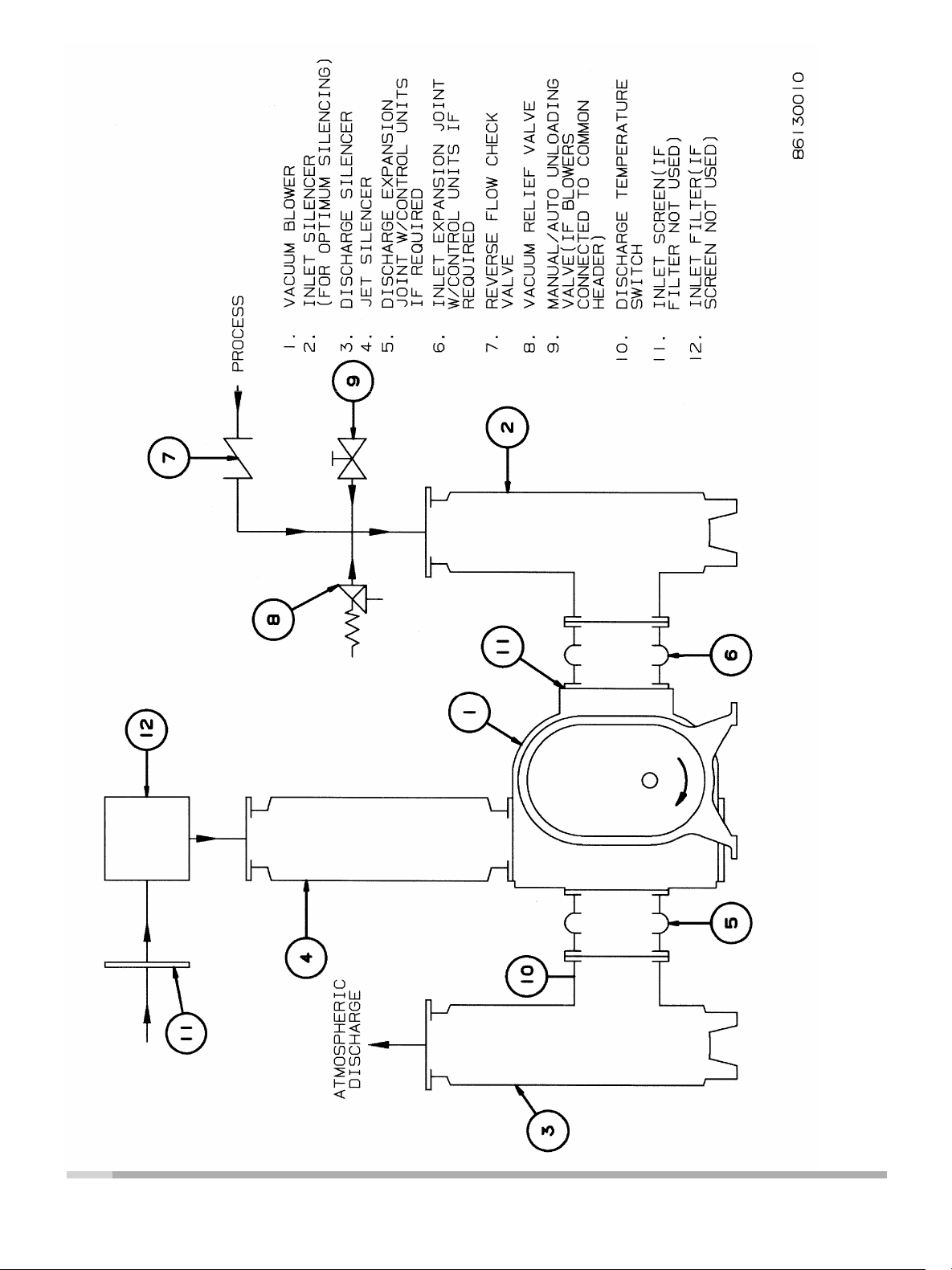
Figure 1 - Schematic Diagram
8
GEA30580_Rev_11.15
Page 9

Lubrication
A very simple lubrication system is employed in these
blowers� All friction parts—gears, bearings and oil
seals—are lubricated by the action of oil slingers
which dip into the main oil sumps causing oil to
splash directly on gears and bearings� Entrance
of lubricating oil into the blower air chamber is
prevented by the use of double shaft sealing� Lip
type seal, located inboard of the bearings in each
headplate, effectively retain oil within the sumps�
Small leakage that may occur, should the seals wear,
passes into a cavity in each headplate that is vented
and drained downward� In addition, sealing rings are
provided on both shafts where they pass through the
inner walls of the headplates� These serve to reduce
air leakage into the air chamber and also minimize oil
carryover into the air chamber�
Oil sumps on each end of the blower are filled by
removing top vent plugs, Item 37, filling until oil
reaches the middle of the oil level sight gauge,
Item 87 with the BLOWER NOT OPERATING, in
order to obtain the correct oil level� Approximate oil
quantities required are listed in Table 1� Use a good
grade of industrial type non-detergent, rust inhibiting,
anti-foaming oil and of correct viscosity per Table 2�
For heavy duty service, a synthetic lubricant, such
as Synfillm GT synthetic oil (Roots p/n 813-106-),
is highly recommended� This synthetic oil has a life
expectancy of 4 times that of petroleum based oils�
The level should never be allowed to fall below the
level gauge when the blower is operating� Oil level
may rise on the gauge during operation, to an extent
depending somewhat on oil temperature and blower
speed, but it should not be permitted to rise above
the top of the oil level gauge�
During the first week of operation, check the oil
levels in the oil sumps about once a day, and watch
for leaks� Replenish as necessary� Thereafter, an
occasional check should be sufficient� It is recommended that the oil be changed after initial 100 hours
of operation� Frequent oil changing is not required
unless the blower is operated in a very dusty location� Normal life expectancy of petroleum based oils
is about 2000 hours with an oil temperature of about
200° F�
Table 1 - Approximate Oil Sump Capacities
Blower
Frame
Size
827V
827H 4�8 2�3 2�0 1�0
GEA30580_Rev_11.15
Gearbox Blind End Cover
Quarts Liters Quarts Liters
2�1 1�0 1�0 0�5
Table 2 - Lubricant Recommended
Ambient Temperature
Above 90°F (32°C) 320
32° to 90°F (0 to 32°C) 220
0° to 32°F (-18 to 0°C) 100
Below 0°F (-18°C) 68
Viscosity Range
SSU @ 100°F (38°C)
Operation
Before operating a blower under power for the first
time, recheck the unit and the installation thoroughly
to reduce the likelihood of avoidable troubles� Use
the following procedure list as a guide, but consider
any other special conditions in the installation�
1� Be certain that no bolts, tools, rags or dirt have
been left in the blower air chamber�
2� Be certain that inlet piping is free of any debris�
If an outdoor intake without filter is used be sure
the opening is located so it cannot pick up dirt
and is protected by a strong screen or grille� Use
of the temporary protective screen at the blower
as described under INSTALLATION is strongly
recommended�
3� Recheck blower leveling, drive alignment and
tightness of all mounting bolts if installation is not
recent�
4� Turn drive shaft by hand to make sure impel-
lers still rotate without bumping or rubbing at any
point�
5� Make sure oil levels in the main oil sumps are
correct�
6� Check lubrication of drive� If it is an electric
motor, be sure that power is available and that
electrical overload devices are installed and
workable�
7� Bump blower a few revolutions with driver to
check that direction of rotation agrees with arrow
near blower shaft, and that both units coast
freely to a stop�
After the preceding points are cleared, blower is
ready for trial operation under “no-load” conditions
as set up under Item 7� The following procedure is
suggested to cover this initial operation test period�
(a) Start the blower, let it accelerate to full speed,
then shut off� Listen for knocking sounds, both
with power on and as speed slows down�
(b) Repeat above, but let blower run 2 or 3 minutes�
Check for noises, such as knocking sounds�
(c) Operate blower for about 10 minutes unloaded�
Check oil levels� Feel cylinder and headplate
surfaces for development of spots too hot to
9
Page 10

touch, indicating impeller rubs� Be aware of any
noticeable increase in vibration�
Assuming that all trials have been satisfactory, or that
necessary corrections have been made, the blower
should now have a final check run of at least one
hour under normal operating conditions� After blower
is restarted, gradually close inlet valve to apply
working vacuum gauge or manometer be connected
into the inlet line if not already provided, and that
termometers be in both inlet and discharge lines�
Readings from these instruments will show whether
vacuum or temperature ratings of the blower are
being exceeded�
During the final run, check operating conditions
frequently and observe the oil levels at reasonable
intervals� If excessive noise or local heating develops,
shut down immediately and determine the cause� If
either vacuum or temperature rise across the blower
exceeds the limit specified din this manual, shut
down and investigate conditions in the piping system
or in the process to which air is being supplied�
Refer to the TROUBLESHOOTING CHECKLIST� For
suggestions on various problems that may appear�
The blower should now be ready for continuous duty
operation at full load� During the first new days make
periodic checks to determine whether all conditions
remain steady, or at least acceptable� This may be
particularly important if the blower is connected
to a process system where conditions can vary�
At the first opportunity, stop the blower and clean
the temporary inlet and jet port protective screens�
If no appreciable amount of debris has collected,
the screen may be removed� See comments under
INSTALLATION� At this same time, verify leveling,
coupling alignment and mounting bolt tightness�
Table 3 - Maximum Allowable Operating Conditions
Inlet Vacuum Temperature Rise
Frame
827 27 684 275 152 2400
Note: Discharge back pressure must not exceed 10" H
Inches
Hg
Mm Hg °F °C
Max
RPM
2
O
Vibration Assessment Criteria
With measurements taken at the bearing locations
on the housings, an unfiltered vibration of 1�0 in/sec
peak is considered an appropriate assessment guide
line for rotary lobe blowers rigidly mounted on stiff
foundations�
If the blower is operating above this level then the
installation must be fully evaluated to determine
the source or cause of the vibration, and the cause
corrected�
Table 4 - Blower Internal Clearances
Frame
Size
827
1
Impellers have “wear in” strips� Impeller strip to case clearances as shown
are expected after running the blower, they will not exist at initial blower
assembly� Assembly records need not indicate the strip to case clearance
values�
Maximum clearance listed is for reference only�
Impeller Ends
Gear End Opp. G.E. Inlet Center Discharge Fronts Backs
�036/�040 �006/�008 �020/�023 �014/�016 �020/�023 �021/�025 �011/�015 275
1
Impeller Strip to Cylinder Impeller Lobes
In general, blower vibration levels should be
monitored on a regular basis and the vibration trend
observed for progressive or sudden change in
level� If such a change occurs, the cause should be
determined through spectral analysis�
Max.
Temp.
Rise
°F
10
GEA30580_Rev_11.15
Page 11
DSIZE
1 6 7 8 9 10 11
E
2 3 4 5
14 88
34
88A
D
SEE
NOTE
#3
62A
62
74
A
SEE NOTE #7
34
B
5
56 57
C
SEE
NOTE
#4
26 106
58 59
F
1
27
1616
38
272828
1610
38
G
Connersville, IN USA
P: 765-827-9200 F: 765-827-9266
PROJECTION
THIRD ANGLE
FINISH IN
µ INCHES
No.
ORDER
ANCHOR BOLT LOCATIONS ±.13
BLOWER INLET & DISCHARGL LOCATIONS ±.25
ALL OTHER DIMENSIONS REFERENCE
DO NOT SCALE FOR DIMENSIONS
ALL DIMENSIONS SHOWN IN BRACKETS [ ] ARE MILLIMETERS
T2:
GEOMETRIC TOLERANCE PER: EP938
T1
SECTIONAL ASSEMBLY
:
TWO PLACE DECIMALS (.XX)---±.015
THREE PLACE DECIMALS (.XXX)--±.005
FRACTIONAL--±1/64
UNLESS OTHERWISE SPECIFIED
DIMENSIONAL TOLERANCES PER
T1:
PATT. No.
5/29/2015
5/29/2015
JJ
. :
RDA
DR.
MAT'L
APP.
CHKD.
B
REV
SHEET 1 OF 1
RC-205203023
827 DVJ - V/H GE DRV
M/D/Y
DATE
5/29/2015
JJ
4"=1'-0"
SCALE
DBV.
SECTION A-A
CAD FILE / DIRECTORY
RC-205203A23 / XASR
90 91
11
28 2854
16
27
21
10 27
1
SEE NOTE #12
38
38
14
29
3
SEE NOTE #7
26106
SEE NOTE #4
SEE NOTE #6
23
7
SEE NOTE #5
26
4
13
30
SEE NOTE #10
8 20
30
SEE NOTE #10
45
12
72
19
SEE NOTE #13
221719
4
40
33
40
88
46
4849
CERTIFIED
PURCHASE ORDER:
PROJECT:
LOCATION:
EQUIPMENT No. :
CERTIFIED BY:
DATE (M/D/Y):
ENGINEER CO:
RDA
16619B
6/30/15
BMS
THIS DRAWING IS CONFIDENTIAL AND IS THE PROPERTY OF HOWDEN ROOTS, LLC. THE DRAWING OR ANY PART THEREOF MUST NOT BE COPIED OR OTHERWISE REPRODUCED OR DIVULGED TO ANY OTHER PARTY, OR USED FOR MANUFACTURE OR OTHER PURPOSE WITHOUT THE EXPRESS PERMISSION OF THE COMPANY.
SPEC SECTION:
REMOVED #31, OGE COVER PLUG
RELEASED
B
A
CONFIDENTIAL AND PROPRIETARY:
MFG. REF. :
F PRIOR TO INSTALLATION ON SHAFT.
CAD FORMAT
8 9 10 11
SOLIDWORKS
APP
CHKD
NOTICE
CHANGE
DATE
M/D/Y
BY
7
REVISIONS
6
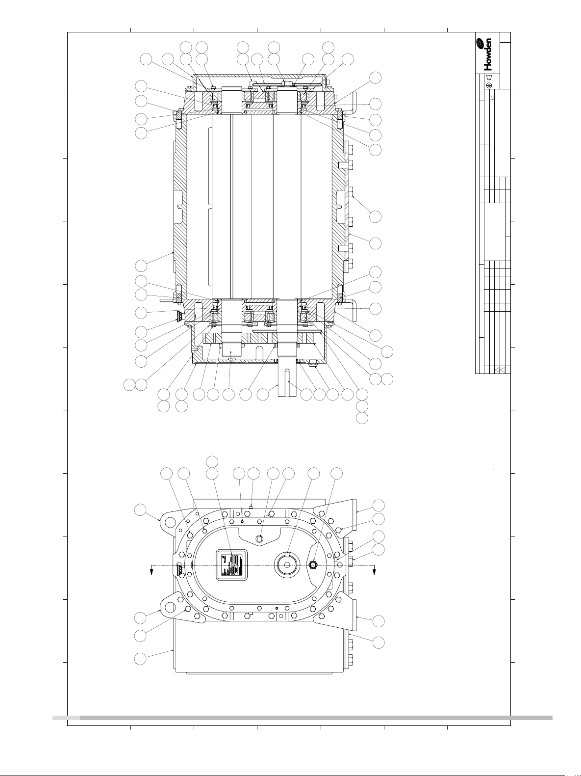
Figure 2 - Sectional Assembly
52 3 41
13. KEY IS TO BE GROUND WITH .001 INTERFERENCE IN SHAFT & .000 INTERFERENCE IN HUB
NOTES:
1. DRIVE END COVER TO BE PINNED TO HEADPLATE AFTER
ALIGNING SEAL BORE TO SHAFT WITHIN .001"
2. USE LOCTITE 567 ON ALL PIPE THREADS
3. APPLY LOCTITE 272 TO SCREW THREADS & TORQUE TO 320 FT-LBS (44.2KG.M)
4. APPLY LOCTITE 272 TO SCREW THREADS & TORQUE TO 23 FT-LBS (3.2KG.M)
5. TORQUE TO 31 FT-LBS (4.3KG.M)
6. TORQUE TO 75 FT-LBS (10.4KG.M)
7. ITEMS 34 & 54 MUST BE INSTALLED WITH OIL GROOVE AT TOP.
8. REFERENCE RP-91T FOR ASSEMBLY CLEARANCES
9. GEAR TO BE INSTALLED WITH ASSEMBLY TOOL TO ACHIEVE MINIMUM PUSH-UP
OF .068". GEAR FIT MUST BE FREE OF OIL.
10. TORQUE NUT TO 500 FT-LBS (69.1KG.M) TORQUE LOCKING SCREW TO 16 FT-LBS
(2.2KG.M)
11. PREPARE PISTON RING GROOVES WITH LIGHT COAT OF SLIP PLATE FOR INITIAL
BREAK IN WEAR.
12. SLEEVE TO BE HEATED TO 300
91 22 44 353690
A
A
63 63
11 44
GEA30580_Rev_11.15
A
B
C
D
E
F
G
11
Page 12

Table 4 - 827 DVJ Parts List
Item Number Quantity Used Identification
1 2 Headplate
3 1 Gearbox
4 1 set Gear
5 1 Cover
7 2 Gasket covers
8 1 Nameplate
9 1 Installation tag
10 1 Shim set
11 1 Cylinder
12 & 13 1 Impeller
14 4 Bearing
16 4 Dowel pin cylinder
17 2 Spring pin
19 1 Key-coupling
20 1 Self-tappign screw
21 2 Breather
22 6 Pipe plug
23 40 Hex head cap screw
26 44 Hex head cap screw
27 4 Oil seal- Inboard
28 4 Piston ring seal
29 2 Wavy washer spring
30 2 Lock nut bearing
33 1 Oil seal- drive shaft
34 2 Brg clamp plate- OGE
35 2 Foot - R/H
36 2 Foot - L/H
38 4 Sleeve - Inboard
40 2 Sight plug
44 18 Hex head cap screw
45 2 Pipe plug
46 1 Slinger
48 2 Washer
49 2 Button head screw
54 2 Brg clamp plate
56 1 Oil leader - R/S
57 1 Oil leader - L/S
58 1 Oil leader - R/S
59 1 Oil leader - L/S
62 1 Hex head cap screw
62A 1 Washer
63 2 Lifting lug
72 4 Pipe plug
74 1
88 4 Steel ball
88A 1 Slinger
90 1 Cover plate
91 12 Hex head cap screw
106 16 Lock washer
Spring pin
12
GEA30580_Rev_11.15
Page 13
OIL LEVEL SIGHT
GAUGE (NEAR SIDE)
800 DVJ DRY VACUUM WHISPAIR BLOWER
INLET AND DISCHARGE FLANGES TO MATE
FLUSH AND SQUARE WITH FLAT FACE
FLANGES ONLY. USE FULL FACE GASKETS
FRAME
BSIZE
MFG. REF. : 73962021
A
CONFIDENTIAL AND PROPRIETARY:
THIS DRAWING IS CONFIDENTIAL AND IS THE PROPERTY OF HOWDEN ROOTS, LLC. THE DRAWING OR ANY PART THEREOF MUST NOT BE COPIED OR OTHERWISE REPRODUCED OR DIVULGED TO ANY OTHER PARTY, OR USED FOR MANUFACTURE OR OTHER PURPOSE WITHOUT THE EXPRESS PERMISSION OF THE COMPANY.
B
C
D
A
REV
6543
AA
P
AA'
BREATHER/FILLER
PLUG
AX
JET INLET
N
INLET
DISCHARGE
V
D
E E
J J
U +.000/-.001
OIL DRAIN
PLUG
A
OIL LEVEL SIGHT
12" FLG 14" FLG
HOLES
(4) REQ'D
H -
GAUGE
17.00 18.75
12.00 14.00
OPENING
BOLT CIRCLE
APPROX.WEIGHT
AX
ALL DIMENSIONS IN INCHES
AW
AA'
AA
X
W - INLET
X - DISCHARGE
AW - JET INLET
W
KEYWAY
V
1"-8
R U
12 12
1.31 1.50
7/8-9
19.00 21.00
P
O
TAP DEPTH
SIZE HOLES
FLANGE O.D.
No. TAPPED HOLES
N
M
5.50 2100
12" FLG
No.
ORDER
9.50 15.75
12" FLG 14" FLG
GEOMETRIC TOLERANCE PER: EP938
.625 x .313
:
PATT. No.
. :
MAT'L
6
Connersville, IN USA
P: 765-827-9200 F: 765-827-9266
SHEET 1 OF 1
RC-204269021
PROJECTION
THIRD ANGLE
FINISH IN
µ INCHES
ANCHOR BOLT LOCATIONS ±.13
BLOWER INLET & DISCHARGL LOCATIONS ±.25
ALL OTHER DIMENSIONS REFERENCE
DO NOT SCALE FOR DIMENSIONS
ALL DIMENSIONS SHOWN IN BRACKETS [ ] ARE MILLIMETERS
T2:
800 DVJ UNITS
T2
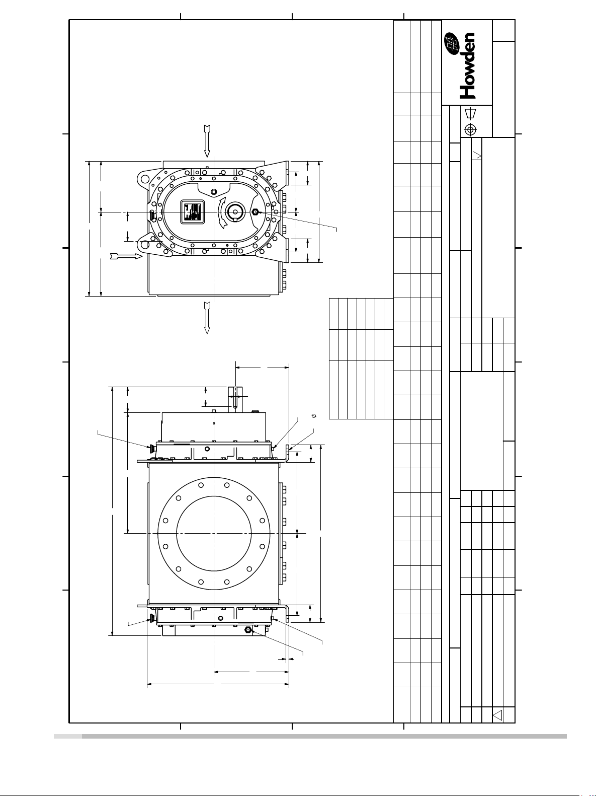
ASSEMBLY DIMENSIONAL
TWO PLACE DECIMALS (.XX)---±.015
THREE PLACE DECIMALS (.XXX)--±.005
FRACTIONAL--±1/64
UNLESS OTHERWISE SPECIFIED
DIMENSIONAL TOLERANCES PER
T1:
M/D/Y
DATE
6/3/2015
5/29/2015
BMS
DR.
CHKD.
5/29/2015
RDA
BMS
SCALE
APP.
DBV.
CAD FILE / DIRECTORY
NTS
3 4 5
RC-204269A21 / XXAD
2
1
GEA30580_Rev_11.15
M
C
BREATHER/FILLER
PLUG
A
K
K
J
F F
H
B
FOR V-BELT DRIVEN UNITS
MOTOR TO BE LOCATED ON
INLET SIDE OF BLOWER
G
F
CERTIFIED
PURCHASE ORDER:
PROJECT:
LOCATION:
ENGINEER CO:
EQUIPMENT No. :
CAD FORMAT
SOLIDWORKS
CERTIFIED BY:
DATE (M/D/Y):
APP
CHKD
2
NOTICE
CHANGE
DATE
M/D/Y
E
BY
K
SPEC SECTION:
G
R
O
B
OIL DRAIN
PLUG
A B C D
827 19.00 33.18 46.54 10.00 7.50 15.34 .50 1.00 4.50 3.25 22.62 4.80 26.50 25.25 14.00 2.625 3.69
SIZE
C
D
1
REVISIONS
RELEASED
A
13
Page 14

Trouble Shooting Checklist
Trouble Item Possible Cause Remedy
1
Speed too low
Check by tachometer and compare with speed on
Roots Order Acknowledgement�
No flow
Low Capacity
Excessive Power
Overheating of bearings
or gears
10
11
12
13
14
15
16
17
2
3
Wrong rotation
Obstruction in piping
Compare actual rotation, change driver rotation if
wrong�
Check piping valve, silencer, to assure open flow
path�
4
5
Speed too slow
Excessive pressure rise
See Item 1�
Check inlet vacuum and discharge pressure and
compare these figures with specified operation
conditions on order�
6
7
Obstruction in piping
Excessive slip
See Item 3�
Check inside of casing for worn or eroded surfaces
causing excessive clearances�
8
9
Speed too high
Excessive pressure rise
Impeller rubbing
See Item 1�
See Item 5�
Inspect outside of cylinder for high temperature
areas, then check
for impeller contact at these points� Look for
excessive scale build-up� Correct blower mounting
drive alignment�
Inadequate lubrication
Excessive lubrication
Check oil sump levels in end covers�
Check oil levels� If correct, drain and refill with clean
oil or
recommended grade
Excessive pressure rise
Coupling misalignment
See Item 5�
Check carefully� Realign if questionable�
Misalignment
Impellers rubbing
Worn bearings/gears
See Item 14�
See Item 10�
Check gear backlash and condition of bearings
and replace as indicated�
Vibration
Driver stops or will not
start
Excessive breather
blowby or
excessive oil leakage to
vent area
18
Unbalanced or rubbing
impellers
Scale or process material may build up on casing
and impellers or inside impellers� Remove build-up
to restore original clearances and impeller balance�
19
20
Driver or blower loose
Piping resonance
Tighten mounting bolts accurately�
Determine whether standing wave pressure pulsa-
tions are present in the piping� Refer to Sales
Office�
21 Impeller stuck Check for excessive hot spot on headplate or cylin-
der� See Item 10� Look for detective shaft, bearing
and/or gear teeth�
22 Broken seal Replace seals
14
GEA30580_Rev_11.15
Page 15

GEA30580_Rev_11�15
15
Page 16

www.howden.com
At the heart of your operations
Howden people live to improve our products and services and for over
160 years our world has revolved around our customers. This dedication
means our air and gas handling equipment adds maximum value to your
operations. We have innovation in our hearts and every day we focus on
providing you with the best solutions for your vital operations.
Howden Roots
Howden Roots
900 W� Mount St�
Connersville
Indiana
USA
47331
Tel: +1 765 827 9200
Web: www�howden�com
©Howden Group Limited� All rights reser ved� 2015�
Howden a nd the flyi ng H logo ar e registe red trad e marks be longi ng to Howden G roup Li mited�
GEA30580_Rev_11�15
 Loading...