

Page 1
www.howden.com
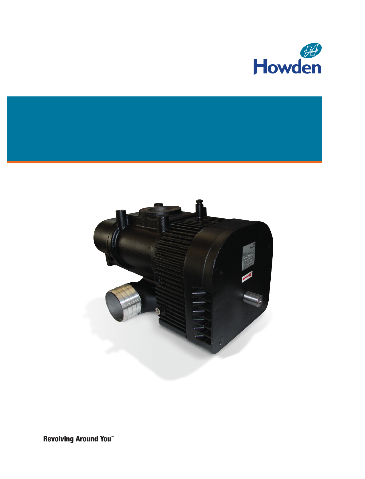
Roots® 412 HPT Blower
Installation Operation & Maintenance Manual
Page 2

ISRB-2009, Rev. 02_17.
Contents
Information Summary ...............................................................2
Safety Precautions ....................................................................3
Operating Limitations ................................................................3
Installation ........................................................................... 4 - 5
Operation......................... .........................................................6
Lubrication........................ ........................................................6
Troubleshooting ........................................................................ 8
Inspection & Maintenance ........................................................9
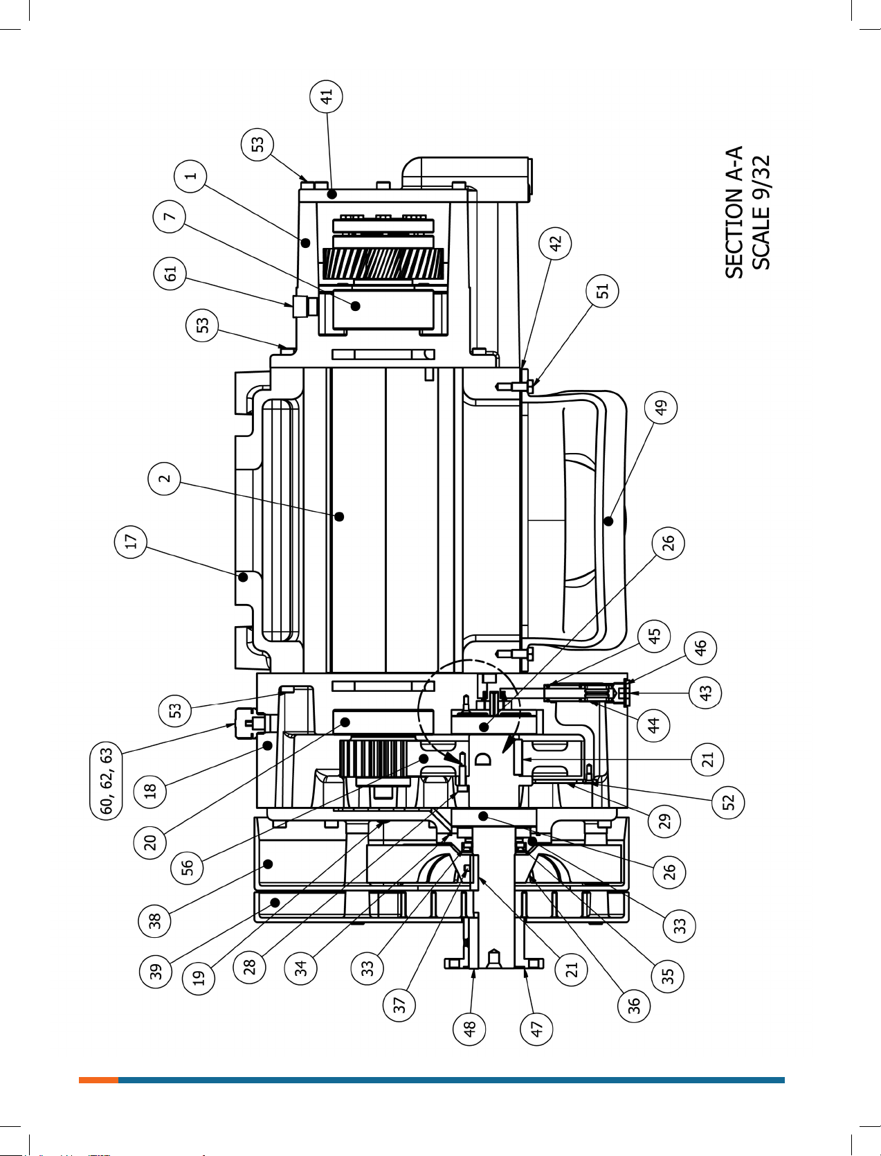
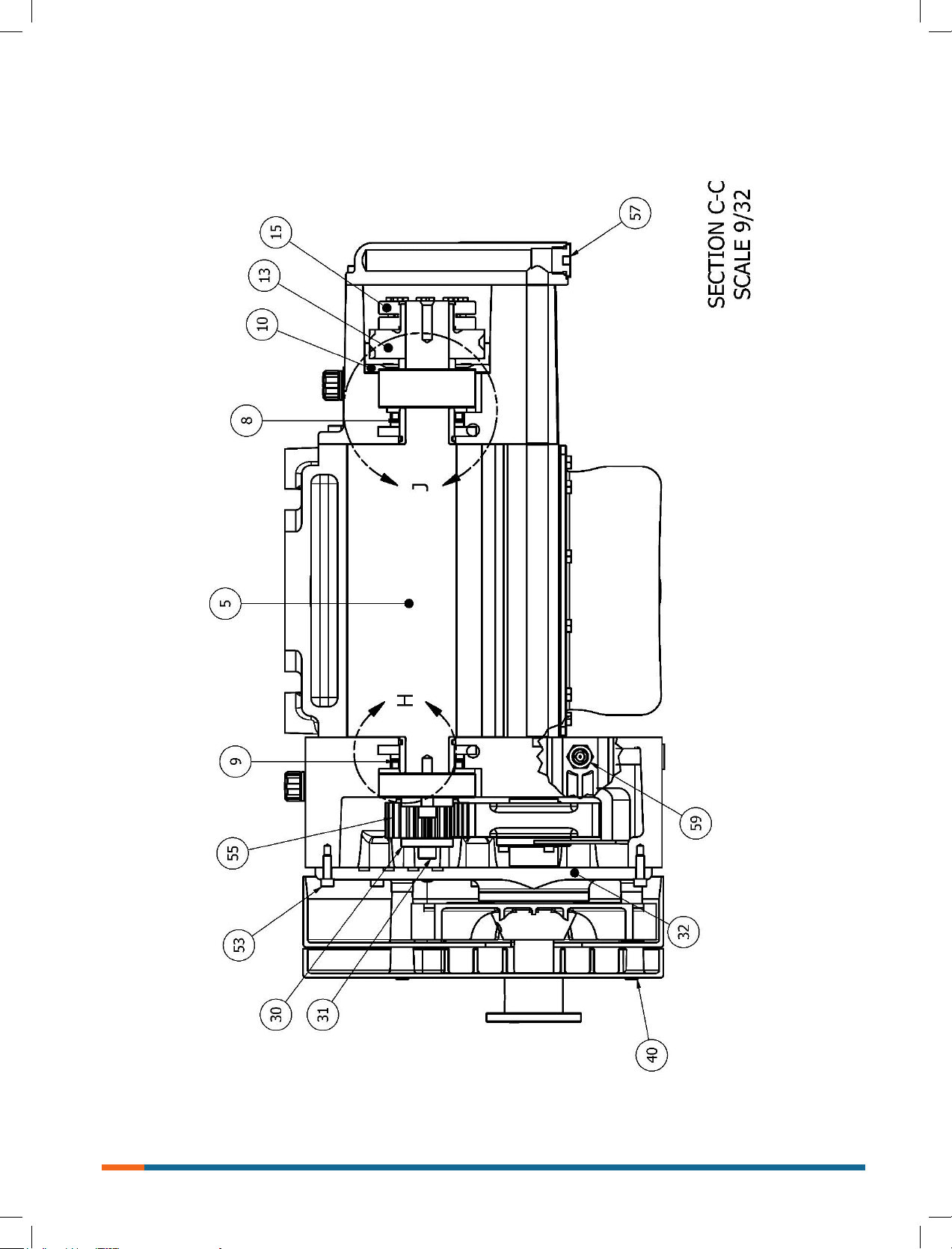
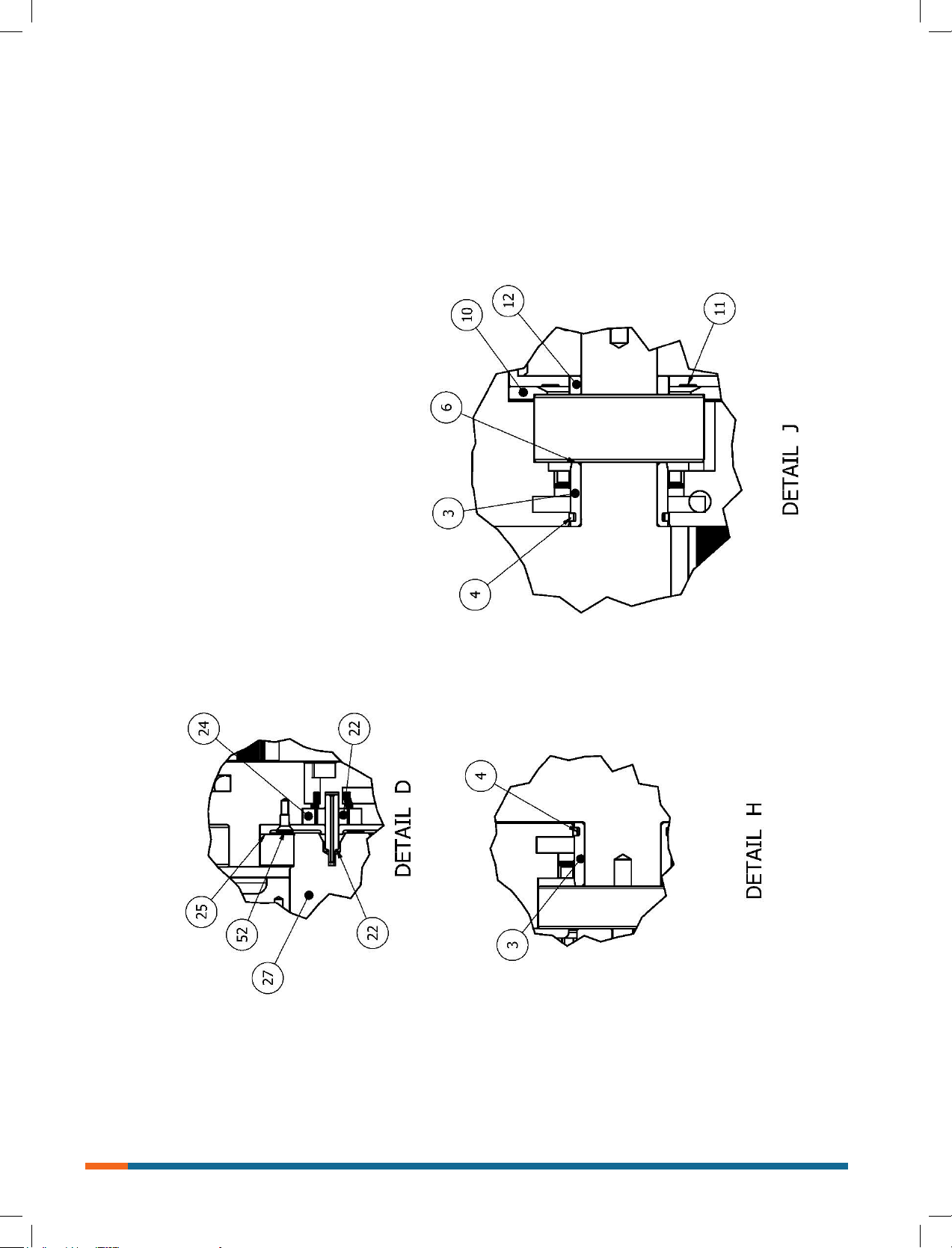
Parts List........................................ .........................................10
Figures..................................... ......................................... 11-14
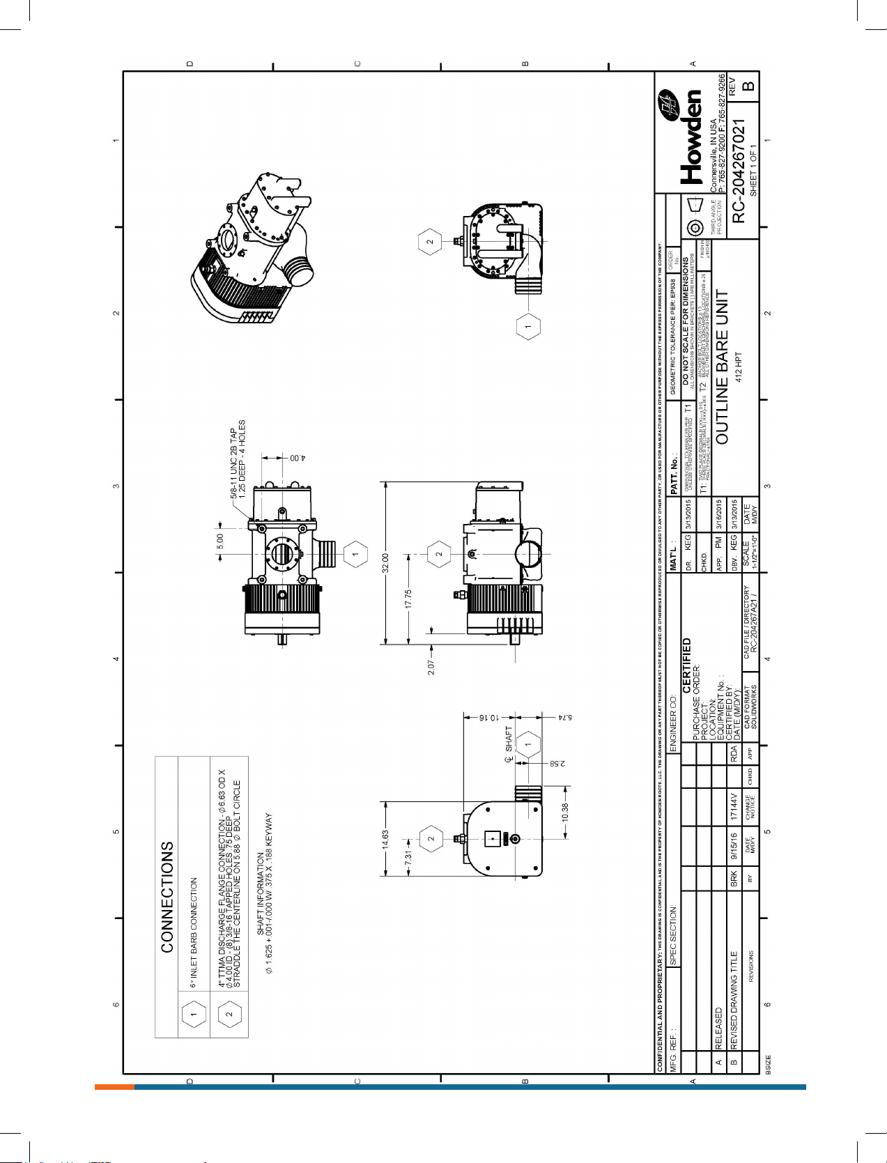
Outline Drawing........................... ...........................................15
Do these things to get the most from your Roots Blower
• Check shipment for damage. If found, le claim with
carrier and notify Howden.
• Unpack shipment carefully, and check contents against
Packing List. Notify Howden if a shortage appears.
• Store in a clean, dry location until ready for installation.
Lift by methods discussed under INSTALLATION to
avoid straining or distorting the equipment. Keep covers
on all openings. Protect against weather and corrosion
if outdoor storage is necessary.
• Read OPERATING LIMITATIONS and INSTALLATION
sections in this manual and plan the complete
installation.
• Provide for adequate safeguards against accidents
to persons working on or near the equipment
during both installation and operation. See SAFETY
PRECAUTIONS.
• Install all equipment correctly. Foundation design
must be adequate and piping carefully done. Use
recommended accessories for operating protection.
Roots products are sold subject to the current General Terms of Sale, ES104 and Warranty Policy WP-5020.
Copies are available upon request.
• Make sure both driving and driven equipment is
correctly lubricated before start-up. See LUBRICATION.
• In event of trouble during installation or operation, do
not attempt repairs of Roots furnished equipment.
Notify Roots, giving all nameplate information plus an
outline of operating conditions and a description of the
trouble. Unauthorized attempts at equipment repair
may void Roots warranty.
• Units out of warranty may be repaired or adjusted by
the owner. Good inspection and maintenance practices
should reduce the need for repairs.
NOTE: Information in this manual is correct as of the date
of publication. Howden reserves the right to make design or
material changes without notice, and without obligation to make
similar changes on equipment of prior manufacture.
For your nearest Howden Oce, dial our Customer Service
Hot Line toll free in the U.S.; 1 877 363 7668 or
direct +1 832 590 2600.
2
Page 3

ISRB-2009, Rev. 02_17.
Safety Precautions
It is important that all personnel observe safety precautions
to minimize the chances of injury. Among many
considerations, the following should be particularly noted:
• Blower casing and associated piping or accessories
may become hot enough to cause major skin burns
on contact.
• Internal and external rotating parts of the blower and
driving equipment can produce serious physical injuries.
Do not reach into any opening in the blower while it is
operating, or while subject to accidental starting.
Protect external moving parts with adequate guards.
• Disconnect power before doing any work, and avoid
bypassing or rendering inoperative any safety or
protective devices.
• If blower is operated with piping disconnected, place a
strong coarse screen over the inlet and avoid standing
in the discharge air stream.
•
CAUTION: Never cover the blower inlet with your
hand or other part of body.
• Stay clear of inlet and discharge openings.
• Stay clear of the blast from pressure relief valves and
the suction area of vacuum relief valves.
• Use proper care and good procedures in handling,
lifting, installing, operating and maintaining the
equipment.
• Casing pressure must not exceed 25 PSI (1725 mbar)
gauge. Do not pressurize vented cavities from an
external source, nor restrict the vents without rst
consulting Roots.
• Do not use air blowers on explosive or hazardous
gases.
• Other potential hazards to safety may also be
associated with operation of this equipment.
All personnel working in or passing through the area
should be trained to exercise adequate general
safety precautions.
Operating Limitations
A Howden Roots blower must be operated within certain
approved limiting conditions to enable continued satisfactory
performance. Warranty is contingent on such operation.
Maximum limits for pressure, temperature and speed are
specied in TABLE 1 for this truck application blower.
These limits apply to this blower of normal construction,
when operated under standard operating conditions.
Be sure to arrange connections or taps for instruments
used to measure temperature, pressure and vacuum at
or near the inlet and discharge connections of the blower.
These, along with tachometer will enable period checks of
operating conditions.
Pressure
The pressure rise, between inlet and discharge, must not
exceed the gure listed in TABLE 1.
• The term “intermittent operation” is dened as operation
for no longer than 10 seconds at maximum pressure list
in TABLE 1, provided that the inlet restriction (lter
pressure drop, etc.) does not exceed 20” (508 mm)
of water.
• Also, in any system where the blower inlet is at a
positive pressure above atmospheric, a maximum
case rating of 25 PSI gauge (1725 mbar) should not
be exceeded. Never should the maximum dierential
pressure be exceeded.
Temperature
Blowers are approved only for installations where following
temperature limits can be maintained in service.
• Measured temperature rise must not exceed listed
values when inlet is at ambient temperature. Ambient
temperature is considered as the general temperature
of the space around the unit. This is not outdoor
temperatures unless unit is mounted outdoors.
• If inlet temperature is higher than ambient, the listed
allowable temperature rise values must be reduced by
2/3 of the dierence between the actual measured inlet
temperature and the ambient temperature. Example:
Tinlet = 150 °F and Tambient = 60 °F; Temperature rise
limit, ∆Tnew = 350 – 2/3(150-60) = 290 °F.
• The ambient temperature of the space the blower/
motor is installed in should not be higher than
120 °F (49 °C).
Speed
This blower may be operated at speeds up to the maximum
listed in TABLE 1. Blower may be direct coupled to suitable
constant or variable speed driver if pressure/temperature
conditions are also within limits. At low speeds, excessive
temperature rise may be a limiting factor.
Special Note: The listed maximum temperature rise may
occur well before its maximum pressure is reached. This
may occur at high altitude, low vacuum or at very low
speed. The blower operating limit is always determined by
the maximum rating reached rst. It can be any one of the
three: Pressure, Temperature or Speed.
3
Page 4
ISRB-2009, Rev. 02_17.
Installation
Howden Roots blowers arrive without lubrication in the sump,
see lubrication section for details.
Howden Roots blowers are treated after factory assembly to
protect against normal atmospheric corrosion. The maximum
period of protection is considered to be one year under
average conditions, if shipping plugs & seals or not removed.
Protection against chemical or salt water atmosphere is not
approved. Avoid opening unit until ready to start installation,
as corrosion protection will be quickly lost due to evaporation.
If there is to be an extended period between installation and
start-up, following steps should be taken to ensure corrosion
protection.
• Coat intervals of cylinder, gearbox and drive end bearing
reservoir with Nox-Rust VCI-10 or equivalent. Repeat
once a year or as conditions may require. Nox-Rust
VCI-10 is petroleum soluble and does not have to be
removed before lubricating. It may be obtained from
Daubert Chemical Co., 2000 Spring Rd., Oak Brook,
IL. 60521.
• Paint shaft extension, inlet & discharge anges and any
other exposed surfaces with Nox-Rust X-110 or
equivalent.
• Seal inlet, discharge and vent openings. It is not
recommended that blower be set in place, piped to the
system, and allowed to remain idle for extended periods.
If any part is left open to the atmosphere, the Nox-Rust
VCI-10 vapor will escape and lose its eectiveness.
• Protect blower from excessive vibration during storage.
• Rotate shaft three to four revolutions every two weeks.
• Prior to start up, remove ange covers on both inlet &
discharge anges and covers on vent opening and
inspect internal clearances. Also, at this time, inspect
gear box intervals thru breather location for rust.
Because of the completely enclosed blower design, location
of the installation is generally not a critical matter. A clean,
dry and protected indoor location is preferred; however, an
outdoor location will normally give satisfactory service. Important requirements are that the correct grade lubricating oil be
provided for expected operating temperatures, and that the
blower be located so that routine checking and servicing can
be performed conveniently. Proper care in locating drive and
accessory equipment must also be considered.
Supervision of the installation by a Howden Roots Service
Engineer is not usually required for these units. Workmen with
experience installing light to medium weight machinery should
be able to produce satisfactory results. Handling of
equipment needs to be accomplished with care, and in
compliance with safe practices. Unit mounting must be solid,
without strain or twist, and air piping must be clean, accurately
aligned and properly connected.
Mounting
Two methods are used to handle a unit. One is to install lifting
lugs into the (4) 5/8-11 tapped holes in top of the unit. Test the
lifting lugs for tightness and potential fractures by tapping with
hammer. In lifting, keep the direction of cable pull on these
bolts as nearly vertical as possible. If unable to use the tapped
holes in top of unit for lifting, lifting slings or a special cradle
may be passed under the unit for vertical lift.
4
Page 5
ISRB-2009, Rev. 02_17.
Bottom inlet, top discharge is standard orientation with CCW
rotation on input drive shaft. Blower can be mounted either
on roadside or curbside of truck chassis. Exact installation
instructions cannot be given because of the variety of truck
chassis available. See SKETCH 1 for basic details. Units are
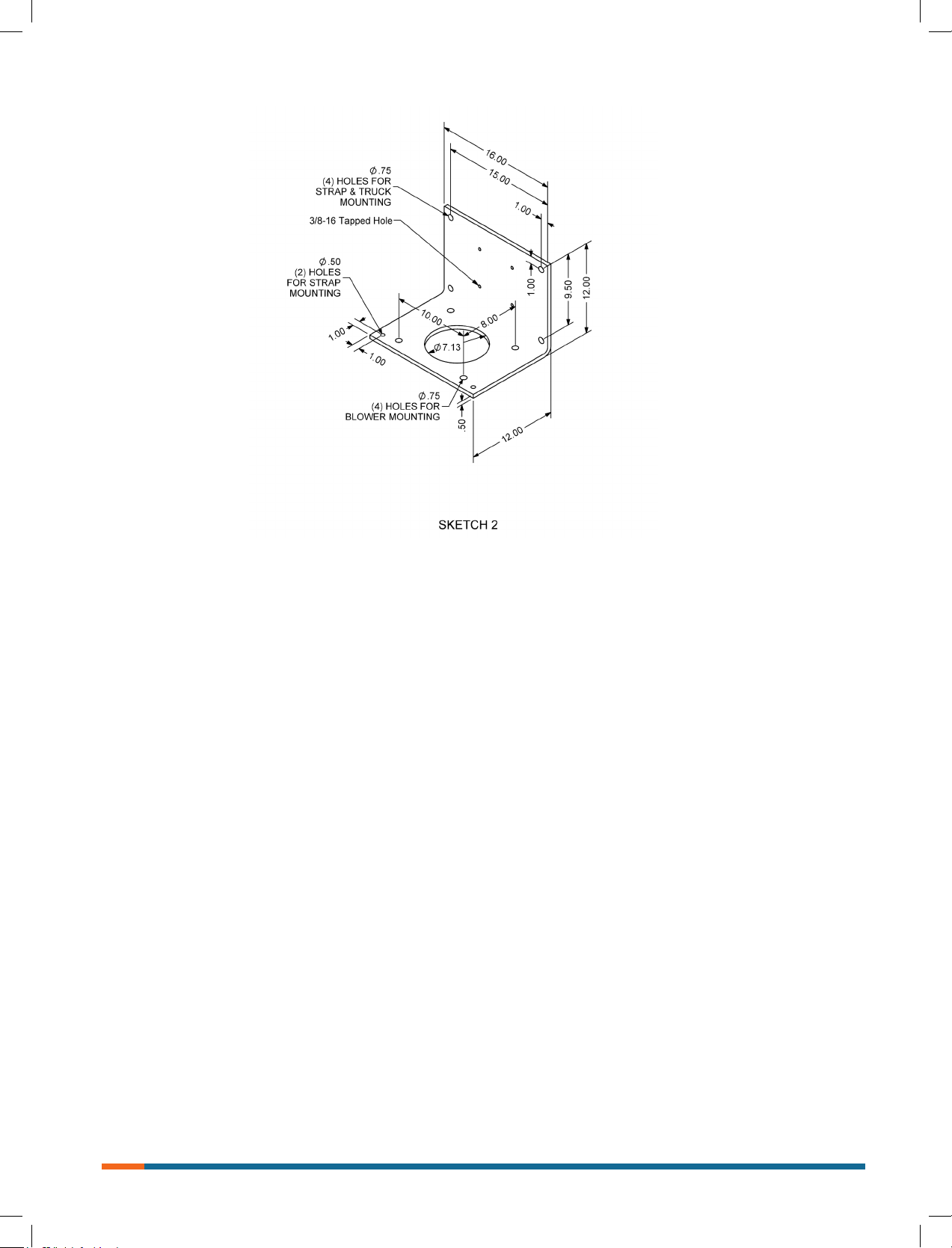
typically held in place on truck chassis by use of “L” shaped
mounting bracket; see SKECH #2 for basic details.
Check output speed range of PTO. It must be for the
blower range.
The blower should be parallel to the truck frame to minimize
vibration.
The PTO shaft must be within the manufacturer’s angularity
limits, not to exceed 5 degrees in the horizontal plane and
3 degrees in the vertical plane.
Brace mounting securely to reduce vibration.
Be sure air lter, oil level gauge, gear case breather and oil
drain plug is not obstructed for normal maintenance.
Do not weld on the blower or base, bearings can be damaged
by the passage of current.
Piping
Install an adequate air lter on blower inlet. Servicing the air
lters is one the most important maintenance operations.
Servicing frequency of lter elements is not time predictable
and must be by the user, depending on dust and moisture
conditions but pressure drop shall never exceed 20” (508 mm)
of water before servicing. Dry lter element life is typically 50
to 300 hours before replacement is necessary. Only replace,
do not reuse dry lter elements via cleaning. Do not allow oil,
grease or solvents to contact the element. Do not operate
blower with damaged lter seals or element. Do not operate
blower without lter element.
WARNING: All piping and accessories downstream of blower
should be rated for the internal pressures being subjected
during full operation.
Insure that inlet and discharge piping are clear, clean and
air tight. Do not allow dirt to enter the blower during piping
operations.
Pressure service, install an air relief valve in discharge line as
close to blower as possible. Vacuum service, install an air relief
valve in inlet line as close to blower as possible. Do not use
any caps, covers, plugs or valves between the blower and
relief valve.
Install a check valve in the discharge line after the relief valve
to prevent back ow of material into the blower and to prevent
reverse rotation of the blower.
Provide a discharge bypass valve to the atmosphere for air
bleed o to lower pressure when too high blower speed thus
ow is present.
Pressure service, install an accurate pressure gauge at or near
the blower discharge. Vacuum service, install an accurate
vacuum gauge at or near the blower inlet.
Install an accurate vacuum gauge or indicator at inlet so able
measure pressure drop across inlet lter.
Provide an adequate sized discharge line. Use as few of
bends as possible; when bends are necessary, use long
radius bends.
Make provisions in piping to allow for expansion as near to
the blower as possible.
Use a dust cover at the nal discharge opening when hose
is removed.
Install discharge silencer after the check valve when additional
noise reduction is required.
5
Page 6

ISRB-2009, Rev. 02_17.
Operation
Before operating blower under power for rst time, recheck
the unit and the installation thoroughly to reduce the likelihood
of avoidable troubles. Use the following procedure check
list as a guide, but consider any special conditions in the
installation.
• Be certain that no bolts, tools, rags, or debris have been
left in the blower air chamber or piping.
• Recheck blower leveling, drive alignment and tightness
of all mounting bolts if installation is not recent.
• Turn drive shaft by hand to make sure impellers still
rotate without bumping or rubbing at any point.
• Ensure oil levels in main sump are correct.
• Bump blower a few revolutions with driver to check that
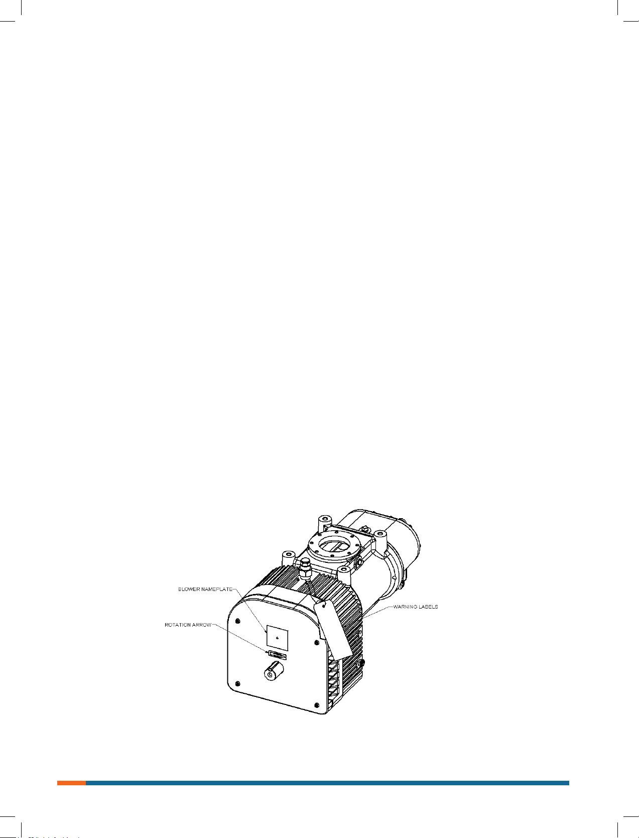
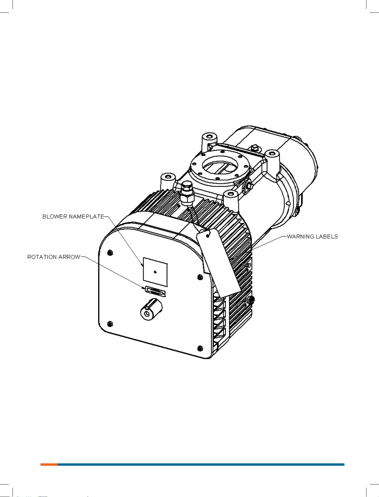
direction of rotation agree with arrow near blower shaft,
and that both coast freely and come to a stop.
After the preceding points are cleared, blower is ready for trial
operation under “no load” conditions. The following procedure
is suggested to cover this initial operation test period.
• Start blower, let it accelerate to full speed slowly, than
shut o. Slowly engage the power take o and never
pop the clutch on engagement. Listen for knocking
sounds, both power-on and as speed slows down.
• After blower comes to complete stop, repeat above but
let run 2 to 3 minutes. Check for noises, such as
knocking sounds.
• After blower comes to complete stop, operate blower for
about 10 minutes unloaded. Check oil levels. Observe
cylinder and head plate surfaces for development of hot
spots such as burnt paint, including impeller rubs.
Be aware of any noticeable increase in vibration.
Assuming that all trials have been satisfactory, or that
necessary corrections have been made, the blower should
now have nal check run of at least one hour under normal
operating conditions. After blower is stated, gradually close
the inlet for vacuum service, or the discharge for pressure
service. At this point it is recommended that pressure gauge
be connected into the discharge line if not already provided,
and that temperature gauge be installed on inlet and
discharge. Readings from these instruments will show
whether pressure or temperature ratings of the blower
are being exceeded.
During the nal run, check operating conditions frequently
and observe the oil levels at reasonable intervals. If excessive
noise or local heating develops, shut down immediately and
determine the cause. If either pressure rise or temperature
rise across the blower exceeds the limit specied in TABLE
1, shut down and investigate conditions in the piping system.
Refer to trouble shooting check list for suggestions on various
problems that may appear.
When the blower vacuum or pressure is at a maximum
intermittent value for over 10 seconds, stop the blower and
remove the line blockage manually. Otherwise the blower
might seize due to excessive operating temperature and
pressure.
Always start blower slowly with power take o and never
pop the clutch on engagement.
Never operate blower above 25 PSI (1.72 bar) pressure rise
on gauge at immediate blower discharge.
Do not operate blower with defective pressure relief valve.
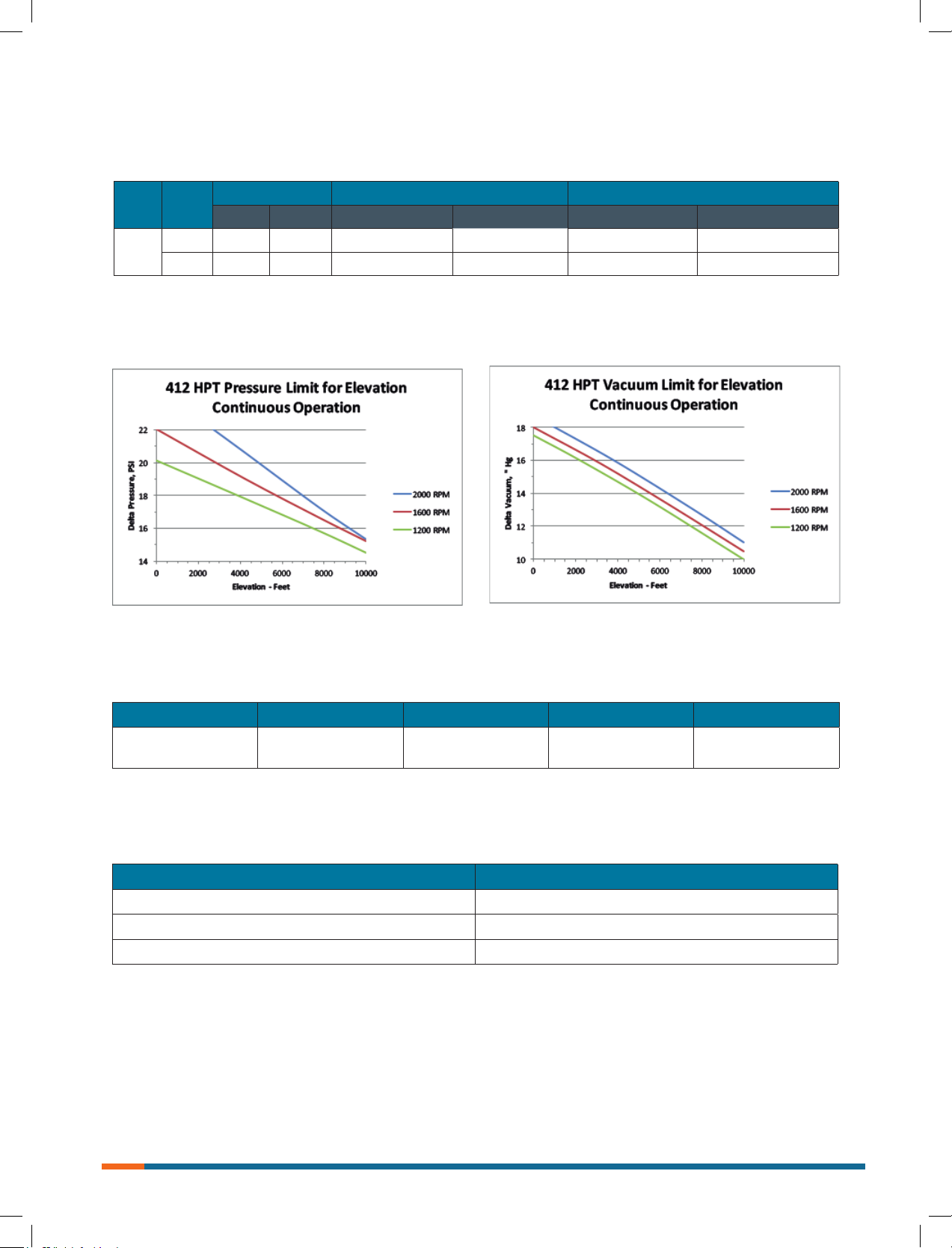
See Table 1, for maximum pressure limits when operating
below maximum speed or above sea level conditions.
See Table 2, for unit internal clearances.
Vibration Assessment Criteria
With measurements taken near the bearing locations on
the housing, see chart below for an appropriate assessment
guide for blower mounted rigidly. In general, blower vibration
levels should be monitored on a regular basis and the
vibration trend observed for progressive or sudden change
in level. As shown on chart below, the level of all pass
vibration will determine need to measure discrete frequency
vibration levels and the action required.
Lubrication
Blower eciency and life depend on the quality of
maintenance the blower receives. Maintenance must be
done regularly and with care. A clean work space, tools,
solvents, and wiping rags are necessary to avoid transfer
of dirt into the unit. A maintenance chart listing each blower
and scheduling regular checks of the unit is valuable.
Any premium grade, non-detergent industrial grade oil with
rust, oxidation and foam inhibitors will be adequate for
use for most applications. Example: Mobile DTE grade oil.
Because of blower design features, the oil temperature will
remain below 220 °F (104 °C) even at maximum blower
operating temperature rise and ambient temperatures of up
to 120 °F (49 °C). Oil life for mineral base oil is 2000 hours if
operating below 180 °F (82 °C). General rule of thumb: Oil
life at 200 °F (93 °C), would be only 1000 hours and at 220
°F (104 °C) would be only 500 hours. Therefore, if expected
to run at the maximum continuous pressure operation or in
elevated ambient conditions, such as inside enclosure or in
warm environments, consider reduction in oil life and change
with more frequency. When oil temperature does reach
above 180 °F (82 °C), also good synthetic grade oil, such as
Roots synthetic can be used to increase oil life by factor of
3X that of mineral base oils.
Oil sump is shared for both ends of the blowers and oil ll
can be accomplished by removing breather (item 60) on
drive end cover and lling to the center of sight glass (item
59) on the side of the reservoir on drive end of blower. Oil
sump capacity is approximately 96 uid ounces (2.85 liters).
Grade of oil to use is based on blower discharge
temperature. See TABLE 3 for recommended oil grades.
NOTE:
Blower discharge temperature of 250 °F, can typically
be achieved ≥ 15 PSI (1000 mbar) pressure rise.
However, can be reached sooner if operating blower
at any of following conditions:
a. higher altitude operation,
b. high ambient temperature,
c. excessive vacuum (inlet lter pressure drop high),
d. lower blower operating speeds.
For operation at temperatures below 10 °F (-12 °C), the
use of heat tracing and synthetic lubricants is recommend.
The pour point should be at least 5 to 10 °F (3 to 5 °C)
below the minimum expected ambient temperature.
For adequate lubrication to the blower internal components,
maximum allowable tilt and roll of the truck is 7.5 degrees
for each direction or in combination.
6
Page 7
ISRB-2009, Rev. 02_17.
Table 1, Maximum Allowable Operating Conditions
Model Speed
412
HPT
2000 335 168 22 (continuous) 1517 (continuous) 18 (continuous) 609 (continuous)
2000 335 168 25 (intermitten) 1725 (intermitten) 19 (intermitten) 643 (intermittent)
Temperature rise Pressure Rise Vacuum
o
F
O
C PSI mbar ''Hg mbar
NOTE: Limited to minimum 1600 RPM operation at 22 PSI continuous pressure, or 18'' Hg continuous vacuum
at sea level conditions.
Table 2, Unit internal clearances, inches (mm)
TE OTE Inlet Fronts Backs
.005 - .007
(.13-.18)
.020 - .027
(.51 - .69)
.005 - .008
(.13 - .20)
.014 - .016
(.36 - .41)
NOTE: Maximum intermittent pressure occurs @ 3 PSI above continuous pressure limit.
TABLE 3, Oil Grade Requirements
Blower discharge temperature Oil grade - ISO
32 oF to 100 oF (0 oC to 38 o C) 100
100 oF to 250 oF (38 oC to 120 oC) 150
Over 250 oF (120 oC) 220
.011 - .014
(.28 - .36)
7
Page 8

ISRB-2009, Rev. 02_17.
Troubleshooting Checklist
Trouble Item Possible Cause Remedy
No ow 1
Low capacity 4
Excessive power 8
Damage to bearings
or gears
Vibration 17
Driver stops, or will
not start
Speed too low
2
Wrong rotation
3
Obstruction in piping
Speed too low
5
Excessive pressure
rise
6
Obstruction in piping
7
Excessive slip
Speed too high
9
Excessive pressure
10
rise
Impeller rubbing
11
Scale, sludge, rust or
product build up
12
Inadequate
lubrication
13
Excessive
14
lubrication
15
Excessive
16
pressure rise
Coupling
misalignment
Excessive belt
tension
Misalignment
18
Impellers rubbing
19
Worn bearings/gears
20
Unbalanced or
rubbing impeller
21
Driver or blower
loose
22
Piping resonances
23
Scale/sludge
24
build-ups
Casing strain
25
Impeller stuck
26
Scale, sludge, rust or
product build-up
Check by tachometer and compare with published
performance.
Compare actual rotation with Figure 1, change driver if wrong.
Check piping, valves, silencer to assure open ow path.
See item 1, if belt drive, check for slippage and re-adjust
tension.
Check inlet vacuum and discharge pressure and compare with
published performance.
See item 3.
Check inside of casing for worn or eroded surfaces causing
excessive clearances
Check speed and compare with published performance.
See item 5
Inspect outside of cylinder for high temperature areas, then check
for impeller contact at these points. Correct blower mounting, drive
alignment.
Clean blower appropriately
Check oil sump levels in gear and drive end headplates
Check oil levels. If correct, drain and rell with clean oil of
recommended grade.
See item 5.
Check carefully. Re-align if questionable.
Re-adjust for correct tension.
See item 15
See item 10
Check gear backlash and conditions of bearings and replace as
indicated.
Scale or process material may build up on casing and impellers, or
inside impellers. Remove build-up to restore original clearances and
impeller balance.
Tighten mounting bolts securely.
Determine whether standing wave pressure pulsations are present
in the piping.
Clean out interior of impeller lobes to restore dynamic balance.
Re-work piping alignment to remove excess strain.
Check for excessive hot spot on headplate or cylinder.
See item 10. Look for defective shaft bearing and/or gear
teeth.
Clean blower appropriately
8
Page 9

ISRB-2009, Rev. 02_17.
Inspection & Maintenance
A good program of consistent inspection and maintenance
is the most reliable method of minimizing repairs to a blower.
A simple record of services and dates will help keep this
work on a regular schedule. Basic service needs are:
• Lubrication
• Checking for hot spots
• Checking for increases or changes in vibration
and noise
• Recording of operating pressures and temperatures
Above all, a blower must be operated within its specied
rating limits, to obtain satisfactory service life.
A newly installed blower should be checked often during
the rst month of full-time operation. Attention there after
may be less frequent assuming satisfactory performance.
Lubrication is normally the most important consideration and
weekly checks of lubricant levels in the gearbox and
bearing reservoirs should be customary. Complete oil
change schedules are discussed under LUBRICATION.
Driver lubrication practices should be in accordance with the
manufacturer’s instructions. If direct connected to the blower
through a lubricated type coupling, the coupling should be
checked and greased each time blower oil is changed. This
will help reduce wear and prevent unnecessary vibration.
In a new, and properly installed, unit there is no contact
between the two impellers, or between the impellers and
cylinder or headplates. Except for impeller strips, which
are intended to wear as necessary as blower temperature rise increases, this wear should be minimal if do not
exceed maximum blower operating temperature riseWear
is conned to the bearings (which support and locate the
shafts) the oil seals, and the timing gears. All are lubricated
and wear should be minimal if clean oil of the correct grade
is always used. Seals are subject to deterioration and wear,
and may require replacement at varying periods.
Piston ring seals (28) are designed to operate without
rubbing contact, once temperature and thermal growth
have stabilized. The stationary rings will rub the rotating
sleeve (38) briey as a result of temperature cycles that
occur during the startup and shutdown of the unit.
The sleeves are hardened and the rings are coated with
dry lubricant that provides for temporary break in wear.
Replace piston ring seals if they become excessively worn.
Shaft bearings are designed for optimum life under
average conditions with proper lubrication and are critical
to the service life of the blower. Gradual bearing wear may
allow a shaft position to change slightly, until rubbing
develops between impeller and casing. This will cause
spot heating, which can be detected by observing these
surfaces. Sudden bearing failure is usually more serious.
Since the shaft and impeller are no longer supported and
properly located, extensive general damage to the blower
casing and gears is likely to occur.
Oil seals should be considered expendable items, to be
replaced whenever drainage from the headplate vent cavity
becomes excessive or when the blower is disassembled for
any reason. Some oil seal leakage may occur since an oil
lm under the lip is required for proper operation.
Periodically leaked oil should be wiped o from surfaces.
Minor seal weepage should not be considered as
indicating seal replacement.
Timing gear wear, when correct lubrication is maintained,
should be negligible. Gear teeth are cut to provide the
correct amount of backlash, and gears correctly mounted
on the shafts will accommodate a normal amount of tooth
wear without permitting contact between lobes of the two
impellers. However, too high an oil level will cause churning
and excessive heating. This is indicated by unusually high
temperature at the bottom of the gear housing. Consequent
heating of the gears will result in loss of tooth-clearance ,
backlash and rapid wear of the gear teeth usually will develop. Continuation of this tooth wear will eventually produce
impeller contacts (knocking), and from this point serious
damage will be unavoidable if blower operation is continued.
A similar situation can be produced suddenly by gear tooth
fracture, which is usually brought on by sustained overloading or momentary shock loads.
Problems may also develop from causes other than internal
parts failure. Operating clearances within a blower are only
a few thousandths of an inch. This makes it possible for
impeller interferences or casing rubs to result from shifts in
the blower mounting, or from changes in piping support. If
this type of trouble is experienced, and the blower is found
to be clean, try removing mounting strains. Loosen blower
mounting bolts and reset the leveling and drive alignment.
Then tighten mounting again, and make sure that all piping
meets blower connections accurately and squarely Foreign
materials sucked into the blower will also cause trouble,
which can only be cured by disconnecting the piping and
thoroughly cleaning the blower interior.
A wide range of causes & solutions for operating troubles
are covered in the TROUBLE SHOOTING CHECKLIST.
The remedies suggested should be performed by qualied
mechanics with a good background. Major repairs generally
are to be considered beyond the scope of maintenance, and
should be referred to your authorized Roots distributor.
Warranty failures should not be repaired at all, unless spe-
cic approval has been obtained through a Sales Oce or
the factory before starting work. Unauthorized disassembly
within the warranty period may void the warranty.
9
Page 10

ISRB-2009, Rev. 02_17.
Item Part Number QTY Description
1 RC-204836023 1 GEAR HSG, BLIND END
2 RC-204844023 1 IMP, DRIVE
3 RC-204742020 4 SLEEVE, SFT
4 12283001 4 PISTON RING
5 RC-204844S23 1 IMP, DRIVEN
6 RC-204743020 2 SHIM, BRG
7 10009028 2 BEARING, DOUBLE ROW ANGULAR CONTACT
8 13309027 2 SEAL, CW
9 13309028 2 SEAL, CCW
10 RC-204263021 2 CLAMP PLATE
11 13034016 16 SOCKET HEAD SCREW, M6-1x12
12 RC-204744020 2 SPACER, TIMING GEAR
13 RC-204617022/RC-204618022 1 TIMING GEAR Set (LH & RH)
15 RC-14029002 2 LOCKING HUB ASSEMBLY
17 RC-204834023 1 CYLINDER
18 RC-204840023 1 GEARBOX, DRV END
19 13230006 6 DOWEL PINS
20 10222060 2 BEARING, CYLINDICAL ROLLER
21 13234010 3 KEY, GEAR
22 RC-204745020 1 DRV PIN, OIL PUMP
23 RC-204750012 1 OIL PUMP, INNER
24 RC-204751012 1 OIL PUMP, OUTER
25 RC-204741020 1 COVER, OIL PUMP
26 10222059 2 BEARING, CYLINDRICAL ROLLER
27 RC-204615012 1 DRIVE SHAFT
28 13034018 3 SOCKET HEAD SCREW, M6-1x20
29 RC-204262021 1 OIL PAN CVR
30 RC-204261021 2 DRV END GEAR/BRG RET
31 13034017 2 SOCKET HEAD SCREW, M12-1.75x35
32 RC-204609022 1 COVER, DRV END
33 RC-204259021 1 SEAL HSG
34 10109533 1 0-RING, VITON, # 2-152
35 13309035 1 SEAL, CCW
36 RC-204613022 1 FAN
37 RC-14073001 1 SET SCREW-FLAT POINT, M6-1X10 (FAN)
38 RC-204842023 1 FAN SHROUD
39 RC-204611022 1 FAN SHROUD COVER
40 13034020 4 SOCKET HEAD SCREW, M8-1.25x90
41 RC-204838023 1 COVER
42 RC-204264021 1 GASKET, INLET ADP
43 RC-204268021 1 OIL FILTER
44 RC-14063001 1 OIL SCREEN
45 10109437 1 O-RING, VITON, # 2-014
46 RC-14072001 1 COPPER RING SEAL
47 N/A 1 Hub, PTO Drive (Supplied by customer)
48 N/A 1 Key, Drive Hub (Supplied by customer)
49 RC-206244023 1 INLET ADAPTOR
51 13690009 8 HEX HEAD CAP SCREW, M8-1.25x16
51 A 13690010 2 HEX HEAD CAP SCREW, M8-1.25 X 130
52 13753003 6 SOCKET SCREW, M5-.8x10 FLAT HD
53 13034019 50 SOCKET HEAD SCREW, M8-1.25x25
55 RC-204260021 1 PINION
56 RC-204616022 1 DRIVE GEAR
57 RC-14074001 2 HOLLOW HEX PLUG, 1-3/16-12 UN 2A
59 12066001 2 SIGHT GLASS
60 13005004 1 BREATHER
61 10008004 2 PIPE PLUG, 1/2" NPT
62 10047004 1 PIPE NIPPLE, 1/2" NPT
63 10078004 1 PIPE UNION, 1/2" NPT
10
Page 11
ISRB-2009, Rev. 02_17.
11
Page 12
ISRB-2009, Rev. 02_17.
12
Page 13
ISRB-2009, Rev. 02_17.
13
Page 14
ISRB-2009, Rev. 02_17.
14
Page 15
ISRB-2009, Rev. 02_17.
15
Page 16
www.howden.com
At the heart of your operations
Howden people live to improve our products and services and for over
160 years our world has revolved around our customers. This dedication
means our air and gas handling equipment adds maximum value to your
operations. We have innovation in our hearts and every day we focus on
providing you with the best solutions for your vital operations.
Howden Roots
Howden Roots
900 W. Mount St.
Connersville
Indiana
USA
47331
Tel: +1 765 827 9200
Web: www.howden.com
©Howden Group Limited. Al l rights reserved. 2017.
Howden a nd the yi ng H logo ar e registe red trade m arks bel onging to H owden Gro up Limite d.
ISRB-2009, Rev. 02_17.
 Loading...