

Howden ENF, ELF, ELFA, E-series Service Manual
Service Manual
Howden 24-07.030r04E 1/25
Warning
Failure to comply with these instructions
could cause serious bodily harm or
property damage and will void the
warranty.
Installation and Maintenance
E-series Axial Flow Cooling Fans

Howden 24-07.030r04 2/25
E-series Axial Flow Cooling Fans
Service Manual
INDEX
I. General Information ........................................................................................................................ 3
Introduction ........................................................................................................................................ 3
Description ......................................................................................................................................... 3
Options / Accessories (at extra cost) ................................................................................................. 3
Field Service ...................................................................................................................................... 3
II. Receiving / Handling / Storage / Disposal .................................................................................... 4
Fan identification ............................................................................................................................... 4
Receiving and unloading ................................................................................................................... 5
Handling ............................................................................................................................................. 5
Storage .............................................................................................................................................. 5
De-commissioning ............................................................................................................................. 6
Exploded view and part list ................................................................................................................ 7
III. Installation ..................................................................................................................................... 8
Required Tools .................................................................................................................................. 8
Rotation and flow direction ................................................................................................................ 8
Preparation ........................................................................................................................................ 8
Coupling flange with parallel bore ..................................................................................................... 9
Coupling flange with tapered bushing ............................................................................................... 9
Hub-plate installation ....................................................................................................................... 10
Blades installation..........................................................................................................................12
Minimum tip-clearance .................................................................................................................... 14
Impeller diameter reduction ............................................................................................................. 15
Retaining plate ................................................................................................................................. 15
Balancing ......................................................................................................................................... 16
IV. Commissioning ............................................................................................................................ 16
V. Preventive Maintenance .............................................................................................................. 18
VI. Contact Howden ......................................................................................................................... 19
VII. Trouble Shooting ....................................................................................................................... 20
VIII. Overview Tightening Torques ................................................................................................. 23
IX. Hardware Overview .................................................................................................................... 24
X. Guideline for acceptable vibration levels of cooling fans in application category BV-3
(according ISO 14694) ...................................................................................................................... 25
XI. Document Version Control ........................................................................................................ 25
Howden 24-07.030r04 3/25
E-series Axial Flow Cooling Fans
Service Manual
Allowable operating temperature
Min.
Max.
All diameters
- 20°C
+ 65°C
- 4°F
+ 149°F
Allowable incidental upset temp. (<12 h)
Max.
Max.
All diameters
+ 80°C
+ 176°F
Maximum tip speed
(As well depends on duty point)
m/s
ft/min
ENF
70
13780
ELF
60
11811
ELFA
46
9055
I. GENERAL INFORMATION
Introduction
This manual provides information necessary to
install, operate and maintain E-series axial
flow cooling fans. Maintenance guidelines and
procedures are given so that your equipment
will operate efficiently, with a minimum of repair or replacement requirements.
Description
Howden E-series fans are most widely used
and are available in three different blade profiles, ENF, ELF & ELFA. Whether you are
looking for a highly efficient impeller and/or a
low noise solution, the E-series offers you a
choice. The fibreglass reinforced polyester
blades have an integral shaft, which eliminates
concentration of stress at mechanical joints.
The FRP blade material offers superior damping of mechanical vibrations and of structure
borne noise compared with metal blades, pro-
longing the fan‟s lifetime. The fan blades are
connected to a polyurethane coated steel hub
with aluminium clamping pieces and A2
stainless steel or ST8.8 galvanised steel Ubolts, nuts and washers for an easy installation
and manual blade pitch variation. The
impellers are connected to the drive shaft by
means of a polyurethane coated cast iron coupling flange, with a cylindrical bore and electrogalvanised hardware.
Howden E-series impellers are in compliance
with EC directive 94/9EC (ATEX 100) for the
equipment of level group II, Category 2, potentially explosive environment class 01. Also respect the instructions in paragraph IV commissioning.
Note: The nomenclature is ‘cooling fans’,
however Howden supplies impellers only. Impellers are components in the sense of European Machinery Directive 98/37/EC.
Table 1: Description table E-series
Options / Accessories (at extra cost)
Coupling flange with tapered bushing
connection, instead of standard cylindrical
bore connection.
Epoxy coating.
A4 stainless steel hardware.
Baked epoxy coating on aluminium
clamping pieces.
Polyurethane leading edge protection for
wet applications or stainless steel leading
edge protection for severe erosion.
Retaining plates to secure the impeller to
the drive shaft.
Bolted clamping piece fastening instead
of location pins, for horizontal drive shaft
applications.
Special impellers for fan selections out-
side the standard design range.
Tools (torque wrench or an inclinometer
for blade pitch adjustment).
Field Service
Howden Service maintains a staff of experi-
enced field service personnel. Their expert
knowledge may be of great assistance at inspection, installation, or to get your fan unit
back in service with a minimum of delay.
Service Manual
Howden 24-07.030r04E 4/25
Leading edge protection for wet cooling tower applications
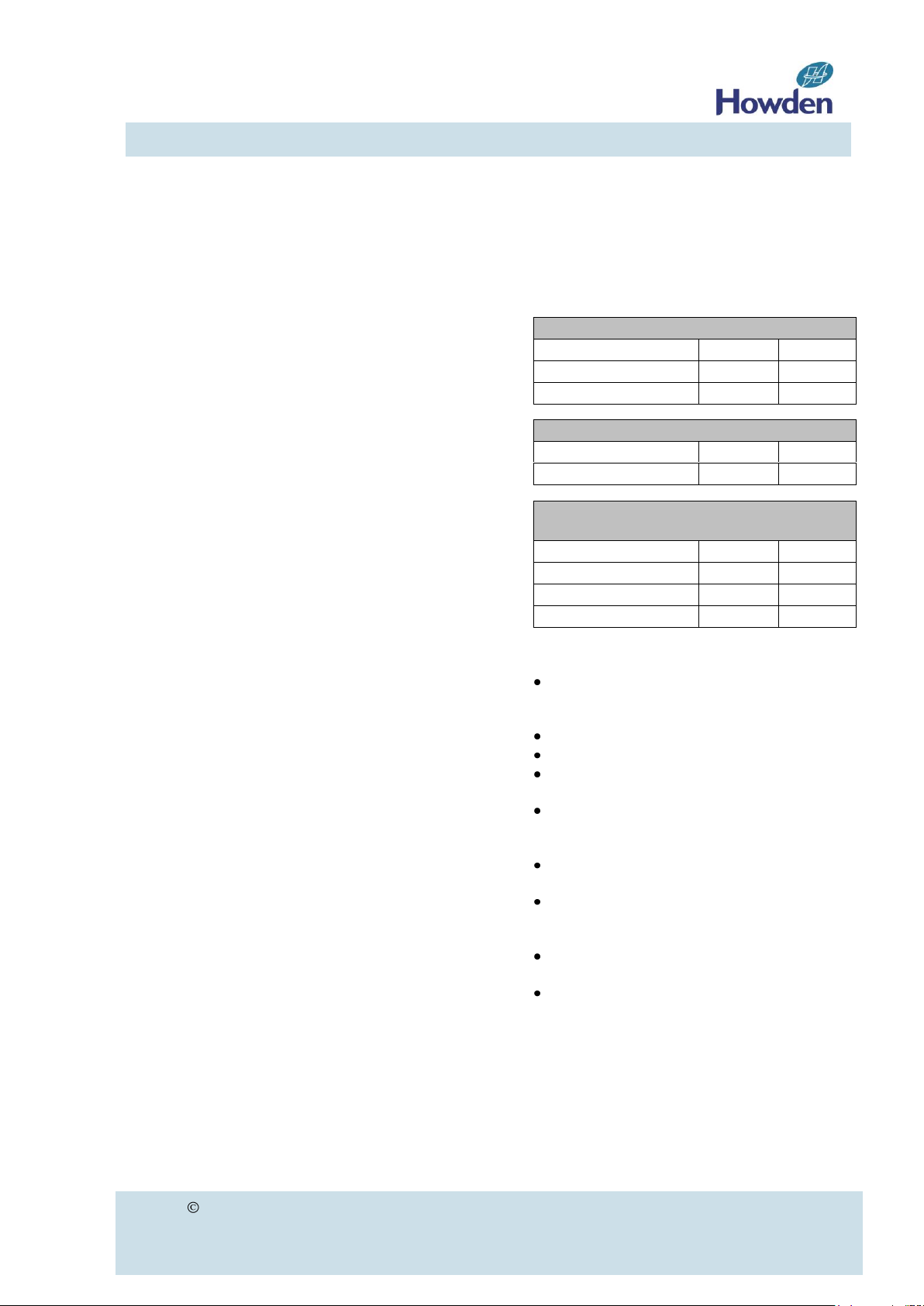
Number of blades: 3,4,5,6,7,8,9
Impeller type: ENF, ELF, ELFA
Fan diameter: metric or imperial (>100 = mm, <100 = feet)
HOWDEN COOLING FANS
Hengelo, The Netherlands
Phone +31-74 2556000
Fax +31-74 2556060
Order No. 103459
Fan type 30ENF6 EP
II. RECEIVING / HANDLING / STORAGE / DISPOSAL
Fan identification
The fan identification code allows identification of the main characteristics of the fan. You can find
this code on the order acknowledgement and packing list included with the shipment.
FAN 30ENF6 EP
Another example:
FAN 8910ELF8
Identifies an ELF fan with a diameter of 8910 mm, 8 blades and without leading edge protection (EP)
The impellers are provided with a product identification plate fixed to the hub plate according the
example below. The unique order number permits future identification of the fan supplied.
Howden 24-07.030r04 5/25
E-series Axial Flow Cooling Fans
Service Manual
Receiving and unloading
Upon unloading this equipment, inspect it for
damage. If damage occurred, file a claim immediately against the carrier and mark the bill
of lading accordingly.
Superficial transport damages like scratches
or small holes may be repaired with touch-up
material (PU filler, e.g. Sikaflex 252).
All consignments are accompanied by a
packing list with the following data:
Order number of the Customer and of
Howden.
Impeller type (fan identification code)
Parts supplied by Howden.
The delivered goods shall be checked upon
arrival for full compliance with the order
and/or the parts count and description stated
on the packing list.
Shortages should be reported to your Howden Contract Engineer within 2 weeks from
receipt of shipment at destination.
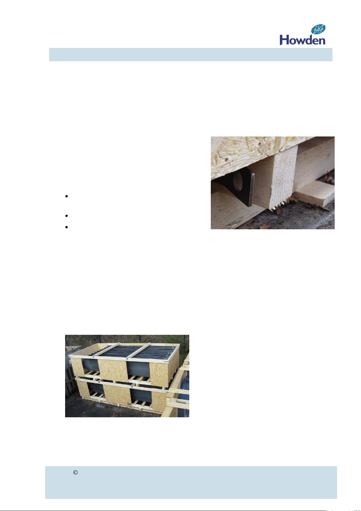
Handling
to allow easy container loading / unloading.
Through these hoist eyes, one can pull the
bunk beds from the container without damaging the fan blades or the crates.
Figure 2
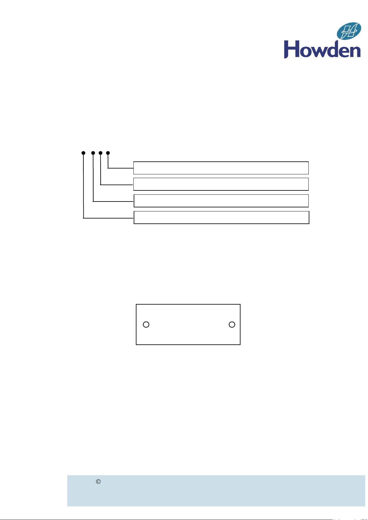
The fan blades can be lifted from the packing
by placing a single sling around the blade.
Position the sling as such that the blade tip is
somewhat hanging down which makes it
easier to move the blades around.
Fan blades of impellers smaller than 26 ft.,
are packed in strong wooden cases or crates.
Fan blades of E-series impellers larger than
26 ft. are packed in so-called “bunk beds” or
specially developed transport frames.
Figure 1
The width of these crates suits standard container dimensions. Fan blades that will be
transported by container sea-freight, are
equipped with and hoist eyes (see figure 2),
Storage
If not installed immediately, it is recommended to store the impeller in a dry and
shaded area.
For long-term storage (in excess of 6 months)
it is necessary to check the condition of the
corrosion protection agent on all machined
surfaces.
Reapply or repair where necessary, using an
acid-free corrosion protection agent (e.g.
Esso Rust ban 397 or equivalent).
You may stack the “bunk beds” to a maximum
of 3 high. Do not allow any heavy materials of
any kind to be stored on top of the blades.

Howden 24-07.030r04 6/25
E-series Axial Flow Cooling Fans
Service Manual
De-commissioning
In accordance with our ISO14001 certified
environmental management system, our
cooling fans can easily be disassembled after
de-commissioning. Their metal components
and polyethylene fan casings are highly
suitable for recycling. Since no viable
recycling procedure for reinforced plastics
exists, fan blades need to be shredded and
incinerated or used as land-fill. The inert
nature of the materials used will prevent
chemical pollution of soil and ground water in
case of in land-fill.
Howden 24-07.030r04 7/25
E-series Axial Flow Cooling Fans
Service Manual
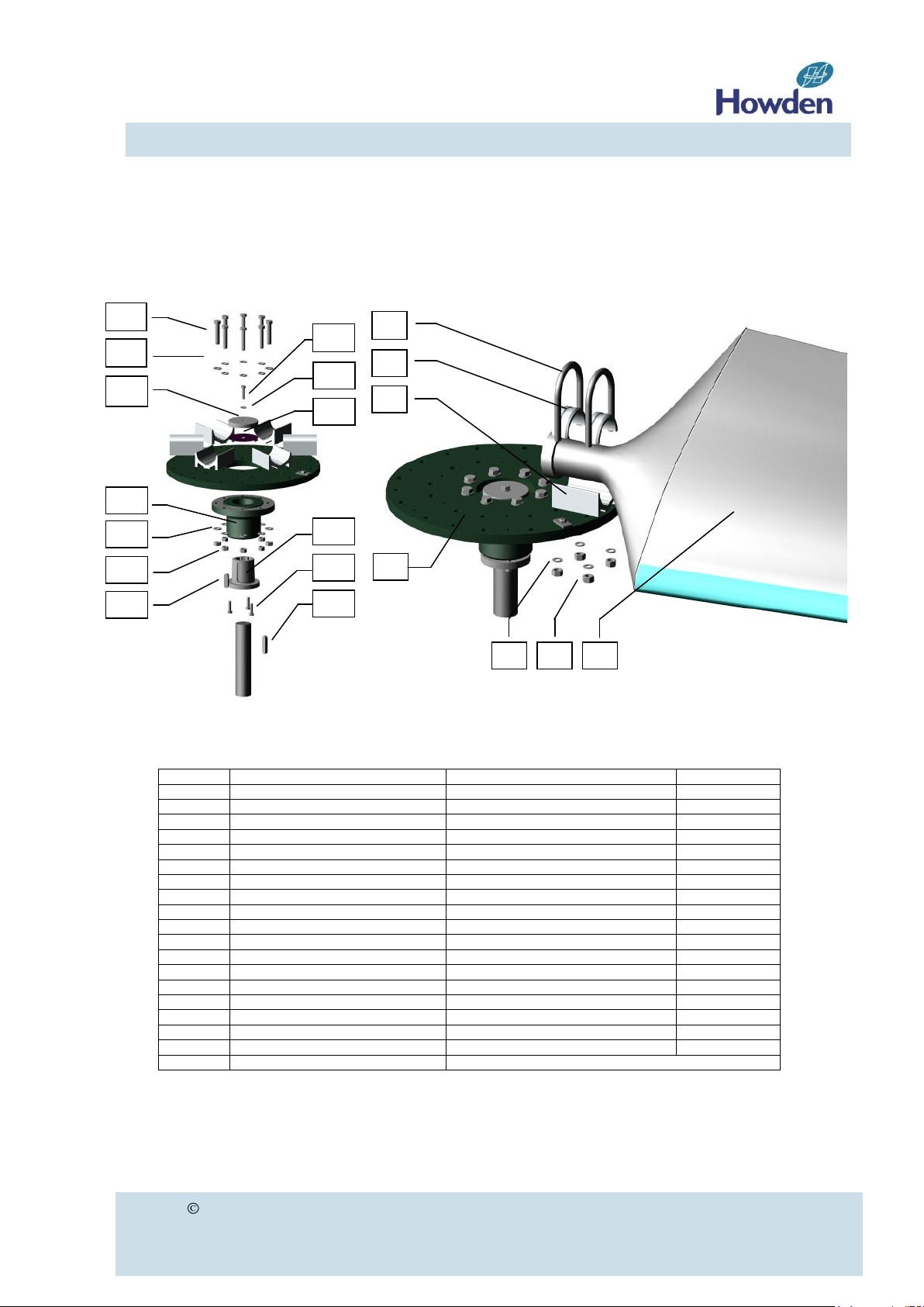
Item
Description
Material (standard construction)
Quantity
1
U-bolt
Stainless steel A2/ steel 8.8
2 / blade
2
Upper clamping piece
Aluminium
2 / blade
3
Lower clamping piece
Aluminium
1 / blade
4
Washer
Stainless steel A2/ steel 8
4 / blade
5
Nut
Stainless steel A2/ steel 8
4 / blade
6
Blade
Fibreglass reinforced polyester
-
7
Hub plate
Polyurethane coated mild Steel
1
8
Coupling flange bolt
Steel class 8.8 electro-galvanised
8 9 Washer
Electro-galvanised
16
10
Nut
Electro-galvanised
8
11
Coupling flange
Nodular cast iron polyurethane coated
1
12
Split tapered bushing
Manufacturers standard
1 (optional)
13
Bolt
Manufacturers standard
3 (optional)
14
Retaining plate
Polyurethane coated steel
1 (optional)
15
Central bolt M16 or M20 or M24
Steel class 8.8 electro-galvanised
1 (optional)
16
Washer
Electro-galvanised
1 (optional)
17
Gasket
Rubber
1 (optional)
18
Key - 1 (optional)
19
Key
Not supplied by Howden
1
2
16
3
4 5 6
15
14
9
8
12
10 9 11
13 7 18
19
17
Exploded view and part list
Figure 3 Figure 4
Table 2
Howden 24-07.030r04 8/25
E-series Axial Flow Cooling Fans
Service Manual
Flow
III. INSTALLATION
Required Tools
Torque wrench (check tightening torques
for the correct model)
Socket and wrench
Inclinometer
Straight edge:
Minimum length > blade width
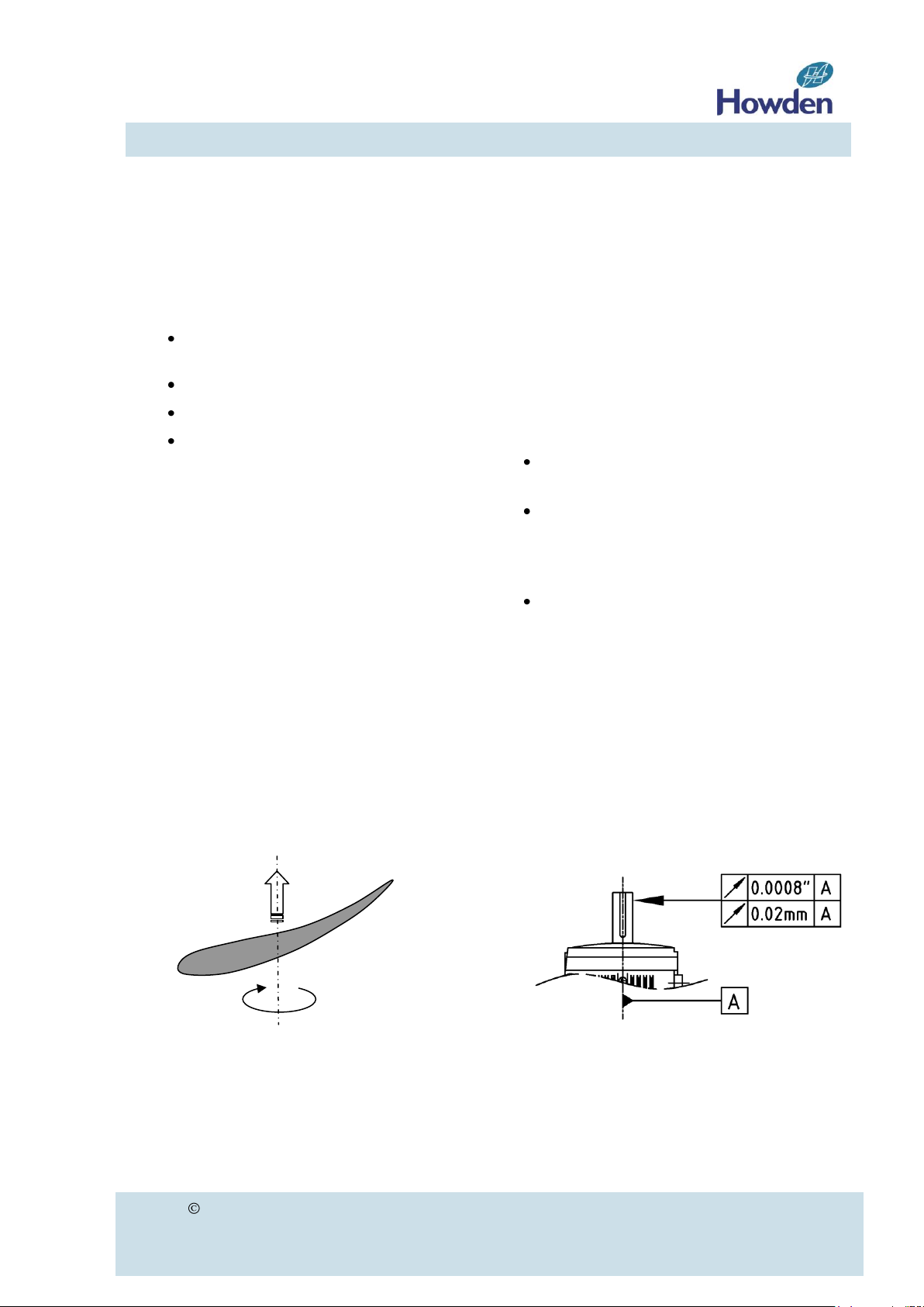
Rotation and flow direction
Standard rotation is clockwise when viewed
into the air-stream. See figure 5.
Preparation
Clean all mating surfaces between shaft, tapered bushing (if applicable) and fan hub. All
corrosion preventive coatings should be removed.
Check the following before parts shall be assembled:
Drainage hole at the blade tip and blade
shoulder shall be open
Make sure the drive shaft is properly cen-
tred with respect to the fan casing. Also
check if the shaft is vertical within the prescribed tolerance.
Check the concentricity of the driver shaft
end before mounting the impeller. The impeller should not be mounted if the con-
centricity error exceeds 0.02 mm (0.0008”)
see figure 6.
Figure 5
Figure 6
Howden 24-07.030r04 9/25
E-series Axial Flow Cooling Fans
Service Manual
Class 8.8 (A3B)
Bolt size
(bushing type)
Torque
(Nm)
Torque
(lb.ft)
5/16” (P2)
22
16
3/8” (Q2, R2)
39
29
½” (S1)
95
70
5/8” (U1)
190
140
3/4” (W1, W2)
339
250
14
19
11
15
16
17
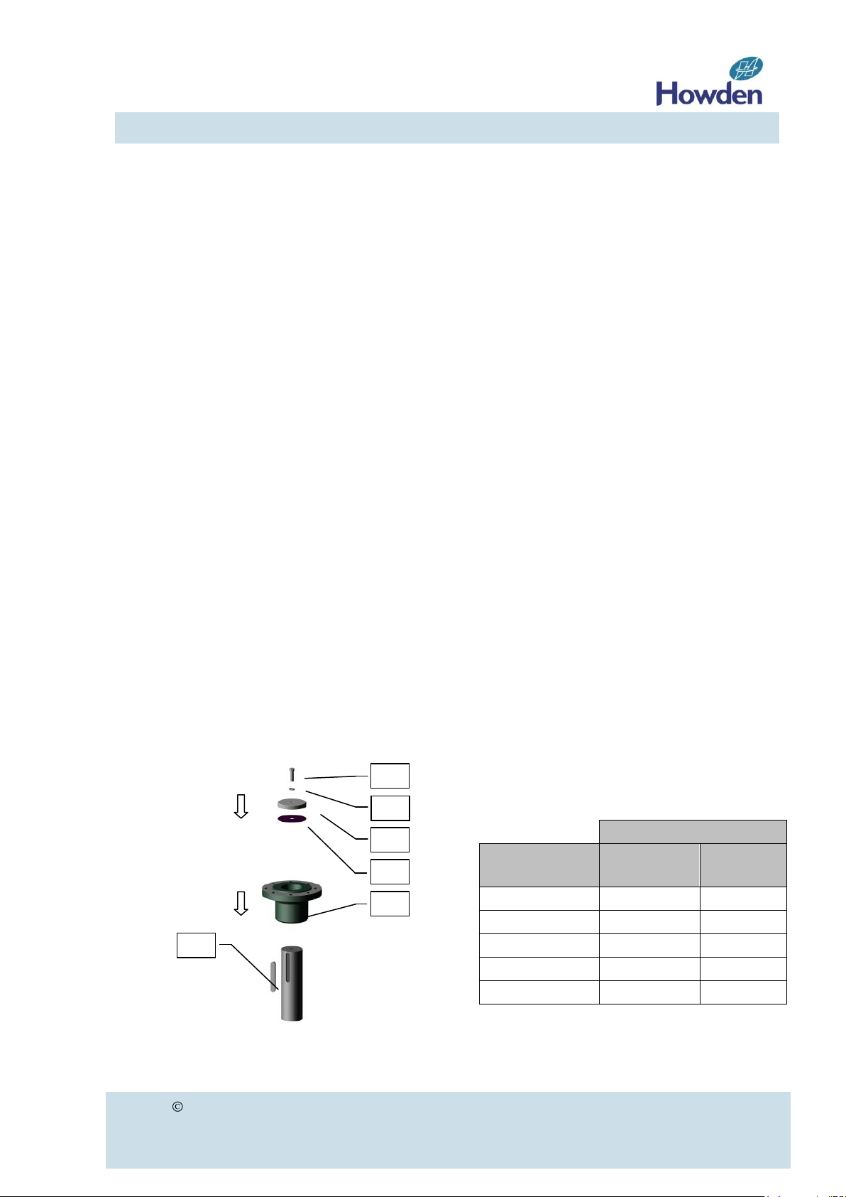
Coupling flange with parallel bore
a) Check if the shaft and bore diameters are
according to specification. The standard
execution has a H7 fit.
b) Slightly lubricate the shaft, the key, and
the bore of the hub with grease.
c) Locate the key (19) into the drive shaft
(figure 7).
d) To slip the coupling flange over the shaft
we advise you to uniformly heat up the
coupling flange up to maximum 120 °C
(248 °F) by means of a hot plate, electric
induction or oil bath, until a 0.15mm difference in diameter is reached. Wear
protective gloves during this operation.
e) Slip the coupling flange (11) onto the
drive shaft and check the key for proper
fit. Be sure the coupling flange is completely through the shaft against the shaft
shoulder.
f) For reverse coupling flange configuration:
(e.g. impeller hanging below the driver)
Install the retaining plate (14) with gasket
(17) and secure it to the shaft with the
lock washer (16) and the central bolt
(15). Supply of retaining plate items 14,
15, 16 and 17 by Howden is optional.
Item 19 (key) is not supplied by Howden.
For torque values of the retaining plate
bolts see table 7 on page 22.
Coupling flange with tapered bushing
(Supply of coupling flange with tapered
bushing is optional).
a) Do not lubricate bushing, coupling flange
bore or hardware. Use of lubricants can
cause coupling flange damage.
b) Slip the bushing onto the drive shaft and
check the key (19) for proper fit (figure 8
on page 10). Be sure the shaft is completely through the bushing. Keep a bolt
length as minimum distance X between
bolts (13) and flange of the drive (figure 9
on page 10).
c) Lock the bushing on the shaft by tighten-
ing the setscrew in the flange. Support
the bushing with a sleeve to prevent it
from sliding down during assembly.
d) Install the coupling flange onto the bush-
ing. Start bolts (13) by hand turning just
enough to engage threads.
e) Keep tightening them as equally as
possible, in several steps, while drawing
the hub onto the bushing until the bushing tightly grips the shaft.
f) Tighten the bolts to the torque shown in
table 3. Do not over-torque. Excessive
torque can cause coupling flange or
bushing damage. Some gap must remain
between the flange of the bushing and
coupling flange in properly tightened assembly.
Torque value for bolts
tapered bushing to coupling flange
Table 3
Figure 7
 Loading...