

Page 1

INSTALLATION AND OPERATION INSTRUCTIONS
FOR
BOTTOM MOUNT REFRIGERATORS AND FREEZERS
INSPECTION
When the equipment is received, all items should be carefully checked against the Bill of Lading
to insure all crates and cartons have been received. Do not sign the freight bill clear until the
freight has been properly inspected for damage. All units should be inspected for damage
including concealed damage by uncrating immediately. If any damage is found, it should be
reported to the carrier at once, noted on the Bill of Lading and a claim should be filed with the
carrier. This equipment has been inspected and tested in the manufacturing facility and has been
crated in accordance with transportation rules and guidelines. The manufacture is not
responsible for freight loss or damages.
INSTALLATION
The unit has been secured to the shipping base with four bolts. Remove these bolts and separate
the unit from the shipping base. Locate the casters or legs found inside the unit. Attach the
casters or legs to the unit base by screwing them into the threaded fittings that were used to
secure the shipping base. Use the wrench provided to tighten the casters to the unit. The casters
with the brakes should be installed on the front of the unit. For proper drainage of condensate,
the unit should be level when placed in its permanent location. Leveling shims are in cluded in
the accessories package in the cabinet. Loosen the casters and insert shims between caster and
bottom of the unit. Retighten the caster.
The exterior of the cabinet and doors have been protected by a plastic covering. Peel this
protective covering before installation. After removing the covering, clean the interior and
exterior surfaces of the unit with soap and water and a rinse with clean water. Do not use
chlorinated cleaners on the surfaces as they can cause corrosion.
If the door(s) have come out of alignment during shipping they will need to be adjusted. This
can be accomplished by opening the door(s) and loosening the screws that hold both the top and
bottom hinges to the cabinet. After adjusting the door so it is aligned correct, tighten the screws
to securely hold the hinges and door(s) in place.
The shelves and self clips are packaged inside the unit. Install the shelf clips on the pilasters
inside the unit and set the shelves on the clips. The shelves are adjustable in ½” increments.
The refrigeration system located at the bottom of the unit requires free air access for proper
operation. Allow a minimum of seven inches between the back of the cabinet and the wall. Do
not locate the unit next to heat generating equipment or in direct sunlight.
Confirm that the proposed electrical outlet has the correct voltage, frequency and current
carrying capacity for the requirements of the unit. This information is noted on the data plate on
the inside left wall of the unit. The unit should be isolated on a circuit. Do not use an extension
cord to get power to the unit. Improper electrical installations will void the compressor
warranty.
1
Page 2

■ MODEL : F23/F49/F72(FREEZER) R23/R49/R72(REFRIGERATOR)
■ MODEL : F23/F49/F72(FREEZER) R23/R49/R72(REFRIGERATOR)
■ MODEL : F23/F49/F72(FREEZER) R23/R49/R72(REFRIGERATOR) ■ MODEL : F23/F49/F72(FREEZER) R23/R49/R72(REFRIGERATOR)
GR26/GR48/GR70(MERCHANDISERS)
GR26/GR48/GR70(MERCHANDISERS)
GR26/GR48/GR70(MERCHANDISERS) GR26/GR48/GR70(MERCHANDISERS)
A. COMMERCIAL FREEZER, REFRIGERATOR GENERAL
1. SPECIFICATION - - - - - - - - - - - - - - - - - - - - - - A2
1. SPECIFICATION - - - - - - - - - - - - - - - - - - - - - - A2
1. SPECIFICATION - - - - - - - - - - - - - - - - - - - - - - A2 1. SPECIFICATION - - - - - - - - - - - - - - - - - - - - - - A2
1) GENERAL
1) GENERAL
1) GENERAL 1) GENERAL
2) MAIN COMPONENTS
2) MAIN COMPONENTS
2) MAIN COMPONENTS 2) MAIN COMPONENTS
2. REFRIGERATION CYCLE - - - - - - - - - - - - - - - - - - - A6
2. REFRIGERATION CYCLE - - - - - - - - - - - - - - - - - - - A6
2. REFRIGERATION CYCLE - - - - - - - - - - - - - - - - - - - A6 2. REFRIGERATION CYCLE - - - - - - - - - - - - - - - - - - - A6
3. TROUBLE SHOOTING - - - - - - - - - - - - - - - - - - - - - A8
3. TROUBLE SHOOTING - - - - - - - - - - - - - - - - - - - - - A8
3. TROUBLE SHOOTING - - - - - - - - - - - - - - - - - - - - - A8 3. TROUBLE SHOOTING - - - - - - - - - - - - - - - - - - - - - A8
1) CHECKING THE POWER SUPPLY
1) CHECKING THE POWER SUPPLY
1) CHECKING THE POWER SUPPLY 1) CHECKING THE POWER SUPPLY
2) CHECKING THE POWER SUPPLY OF CONTROL BOARD
2) CHECKING THE POWER SUPPLY OF CONTROL BOARD
2) CHECKING THE POWER SUPPLY OF CONTROL BOARD 2) CHECKING THE POWER SUPPLY OF CONTROL BOARD
3) CHECKING THE CONTROL PART OF REFRIGERATION CYCLE
3) CHECKING THE CONTROL PART OF REFRIGERATION CYCLE
3) CHECKING THE CONTROL PART OF REFRIGERATION CYCLE 3) CHECKING THE CONTROL PART OF REFRIGERATION CYCLE
4) CHECKING THE DEFROST PART
4) CHECKING THE DEFROST PART
4) CHECKING THE DEFROST PART 4) CHECKING THE DEFROST PART
5) WHEN THE UNIT DOES NOT COOL
5) WHEN THE UNIT DOES NOT COOL
5) WHEN THE UNIT DOES NOT COOL 5) WHEN THE UNIT DOES NOT COOL
6) WHEN THERE IS A ABNORMAL NOISE
6) WHEN THERE IS A ABNORMAL NOISE
6) WHEN THERE IS A ABNORMAL NOISE 6) WHEN THERE IS A ABNORMAL NOISE
7) WHEN THE TEMPERATURE DOES NOT DISPLAY
7) WHEN THE TEMPERATURE DOES NOT DISPLAY
7) WHEN THE TEMPERATURE DOES NOT DISPLAY 7) WHEN THE TEMPERATURE DOES NOT DISPLAY
8) WHEN THE LAMP DOES NOT LIGHT
8) WHEN THE LAMP DOES NOT LIGHT
8) WHEN THE LAMP DOES NOT LIGHT 8) WHEN THE LAMP DOES NOT LIGHT
9) CHECKING SENSOR
9) CHECKING SENSOR
9) CHECKING SENSOR 9) CHECKING SENSOR
4. FEATURE CHART - - - - - - - - - - - - - - - - - - - - - - - A18
4. FEATURE CHART - - - - - - - - - - - - - - - - - - - - - - - A18
4. FEATURE CHART - - - - - - - - - - - - - - - - - - - - - - - A18 4. FEATURE CHART - - - - - - - - - - - - - - - - - - - - - - - A18
5. WIRING DIAGRAM - - - - - - - - - - - - - - - - - - - - - - A30
5. WIRING DIAGRAM - - - - - - - - - - - - - - - - - - - - - - A30
5. WIRING DIAGRAM - - - - - - - - - - - - - - - - - - - - - - A30 5. WIRING DIAGRAM - - - - - - - - - - - - - - - - - - - - - - A30
6. REPLACEMENT OF COMPONENTS - - - - - - - - - - - - - - - - - A35
6. REPLACEMENT OF COMPONENTS - - - - - - - - - - - - - - - - - A35
6. REPLACEMENT OF COMPONENTS - - - - - - - - - - - - - - - - - A35 6. REPLACEMENT OF COMPONENTS - - - - - - - - - - - - - - - - - A35
-A1 -
Page 3
1. SPECIFICATION
AC 115V
60Hz
1. SPECIFICATION
1. SPECIFICATION 1. SPECIFICATION
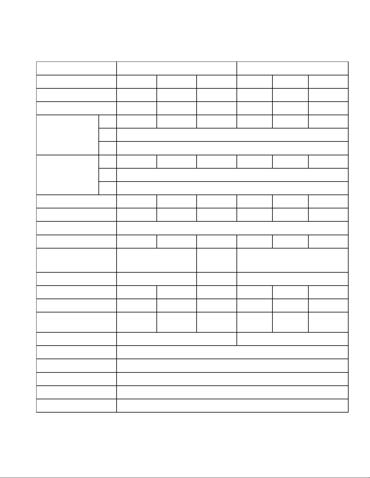
1) GENERAL - COMMERCIAL FREEZERS AND REFRIGERATORS
1) GENERAL - COMMERCIAL FREEZERS AND REFRIGERATORS
1) GENERAL - COMMERCIAL FREEZERS AND REFRIGERATORS1) GENERAL - COMMERCIAL FREEZERS AND REFRIGERATORS
PRODUCT
MODEL
Capacity (Cu,Ft)
Net Capacity (Cu,Ft)
Exterior Dimension
(Including casters)
(in)
Interior Dimension
(Including casters)
(in)
Net Weight (lbs)
Door Type
Door Material
Shelves
SOLID DOOR FREEZER SOLID DOOR REFRIGERATOR
F23 F49 F72 R23 R49 R72
23 49 72 23 49 72
20.8 45.2 65.3 20.8 45.2 65.3
(W) 27.4 55.1 78 27.4 55.1 78
(D)
(H)
(W) 23.6 51.4 74.2 23.6 51.4 74.2
(D)
(H)
295 499 622 288 475 609
Swing 1EA Swing 2EA Swing 3EA Swing 1EA Swing 2EA Swing 3EA
Stainless steel (STS)
4EA 8EA 12EA 4EA 8EA 12EA
31.3
83.9
25
60.8
Power Voltage
Plug in - Installation
Amps
Compressor
Refrigerant
Range of Temperature
Door auto-close equipment
Door stop equipment
Air suction equipment
Condensing unit
AC 115V/60Hz
NEMA 5-15P
8.5A 9.5A 9.0A 7.5A 7.5A 10.0A
1/2HP 3/4HP 1.1HP 3/8HP 3/8HP 1/2HP
R-404A
(12.0 oz)
R-404A
(22.2 oz)
Below 0 ℉
/208-230V
NEMA 14-20P
R-404A
(23.6 oz)
Auto-close Spring
120˚ Stop
Air damper
4in × 4EACaster
Sliding Type
R-134A
(8.5 oz)
AC 115V/60Hz
NEMA 5-15P
R-134A
(11.3 oz)
32 ~ 40 ℉
◈ Above specifications are subjected to change without prior notice for quality improvement.
◈ The nameplate(includes Serial Number) is located on the upper left of the cabinet interior.
R-134A
(14.1 oz)
-A2 -
Page 4
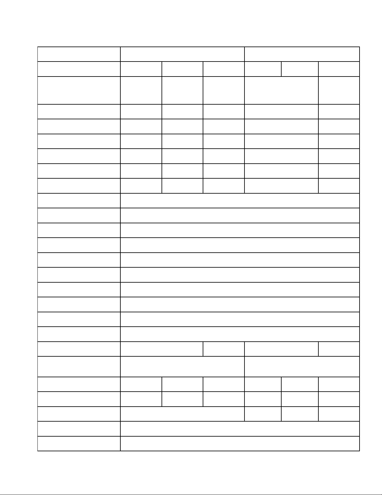
2) MAIN COMPONENTS - COMMERCIAL FREEZERS AND REFRIGERATORS
2) MAIN COMPONENTS - COMMERCIAL FREEZERS AND REFRIGERATORS
2) MAIN COMPONENTS - COMMERCIAL FREEZERS AND REFRIGERATORS2) MAIN COMPONENTS - COMMERCIAL FREEZERS AND REFRIGERATORS
PRODUCT
MODEL
Compressor
(Manufacture)
Compressor Capacity(kcal/h)
Type of Compressor motor
Compressor O.L.P
Compressor Relay
Starting Capacitor
Running Capacitor
Type of Evaporator
Evaporator pipe Dimensions
Cooling Fan Motor
SOLID DOOR FREEZER SOLID DOOR REFRIGERATOR
F23 F49 F72 R23 R49 R72
CAE2420Z(A)
(Tecumseh)
CAJ2432Z(A)
(Tecumseh)
CAJ2446Z(H)
(Tecumseh)
LBP 571 LBP 808 LBP 1219 LBP 1586
CSIR CSR CSR CSIR
MST16AHN GA3PJU00 MST00AHN GA3SJU81
3ARR3*5R* 3ARR3*3A* 3ARR18A100B
315㎌/160V 315㎌/160V 88㎌/160V 250㎌/160V
- 30㎌/400V 15㎌/160V -
SK6A1C-H2Y
(Samsung)
HBP 1120
RSIR
4TM811XHBZZ-53
MTRP0052-02
-
-
CAJ4476Y(A)
(Tecumseh)
Cu pipe + Al fin + Blue color coating
3/8"
IS3225LTSA, 120V/60Hz
Type of Condenser
Condenser pipe Dimensions
Condenser Fan Motor
Drier
Temperature Control
Running Indication
Interior Temp. Indication
Interior Lamp
Defrost for evaporator
Defrost sheath heater
Defrost pan heater
Drain heater
Cu pipe + Al fin
3/8"
MA7425W1, 120V/60Hz
OD 1", XH-9, 1.06oz
Thermistor
Digital Display
Digital Display
40W × 1EA 40W × 1EA
Heated defrost
(Control of thermistor)
40W × 2EA 40W × 2EA
Off cycle
450W 670W 944W - - -
60W 90W 128W - - -
9W
- - -
Door switch
Power switch
SP201R-7DR, AC125V
SL112A, AC125V/12A
-A3 -
Page 5
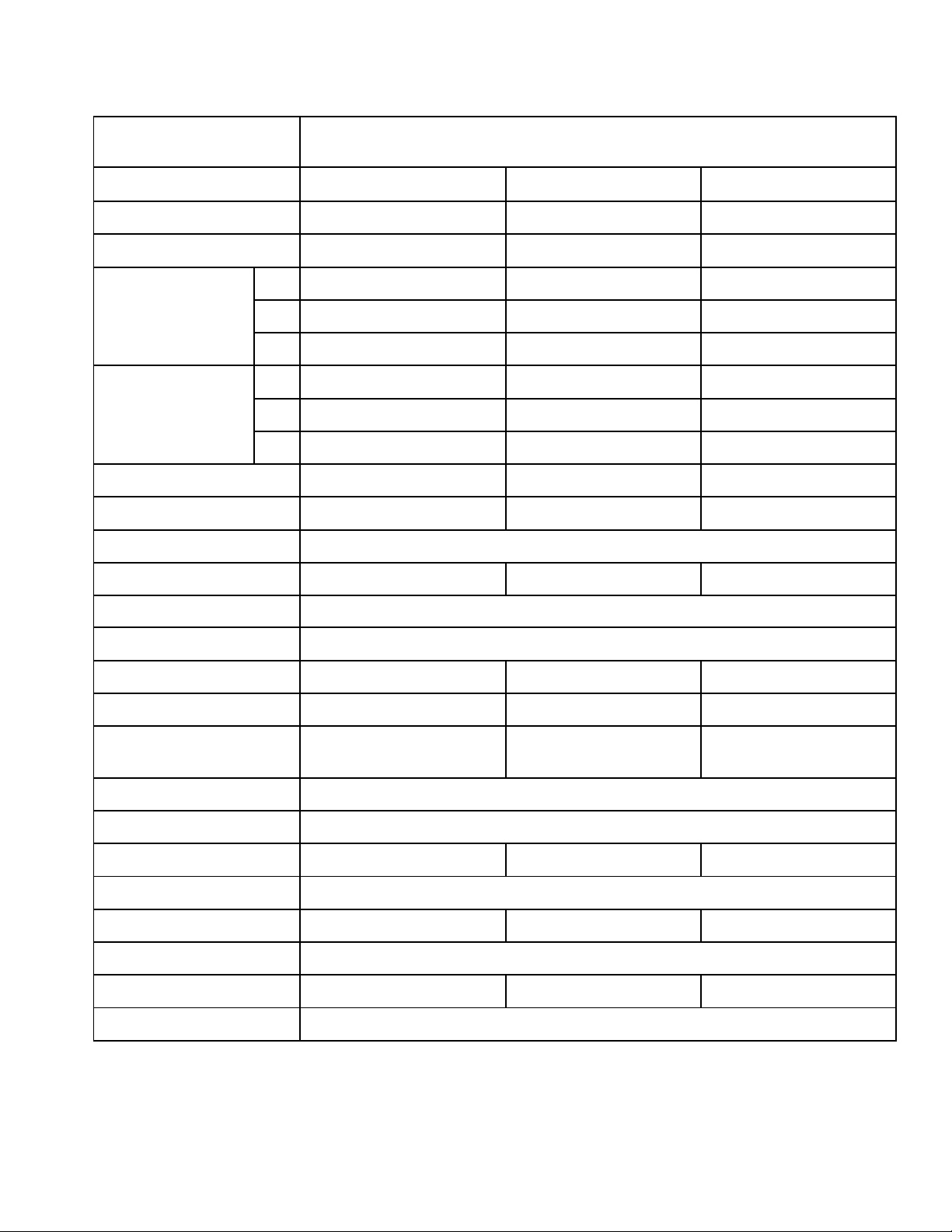
3) GENERAL - MERCHANDISERS
3) GENERAL - MERCHANDISERS
3) GENERAL - MERCHANDISERS3) GENERAL - MERCHANDISERS
PRODUCT
MODEL
Capacity (Cu,Ft)
Net Capacity (Cu,Ft)
Exterior Dimension
(Including casters)
(in)
Interior Dimension
(Including casters)
(in)
Net Weight (lbs)
Door Type
Door Material
Shelves
(W)
(D)
(H)
(W)
(D)
(H)
MERCHANDISERS
GR26 GR48
26 48
24.4 45.3 65.3
28.4
31.3
78.7
25
27
62.5
287
4EA 8EA 12EA
53.2
29.9
78.7
50
25.5
61.4
474 716
Glass + Al
GR70
70
78
31.3
83.9
74.2
25
60.8
Swing 3EASwing 1EA Sliding 2EA
Power Voltage
Plug in - Installation
Compressor
Refrigerant
Range of Temperature
Door auto-close equipment
Door stop equipment
Air suction equipment
Caster Adjust foot 4EA
Condensing unit
Door switch
Power(or Lamp) switch
3.9AAmps
1/4 HP 1/2 HP
R-134A
(10.6 oz)
120˚ Stop - 120˚ Stop
-
AC 115V/60Hz
NEMA 5-15P
10.0A
R-134A
(16.2 oz)
32 ~ 40℉
Auto-close Spring
Air damper
Adjust foot 6EA
Sliding Type
-
SL112A, AC125V/12A
Adjust foot 6EA
◈ Above specifications are subjected to change without prior notice for quality improvement.
11.9A
1/2 HP
R-134A
(17.6 oz)
-
◈ The nameplate(includes Serial Number) is located on the upper left of the cabinet interior.
-A4 -
Page 6
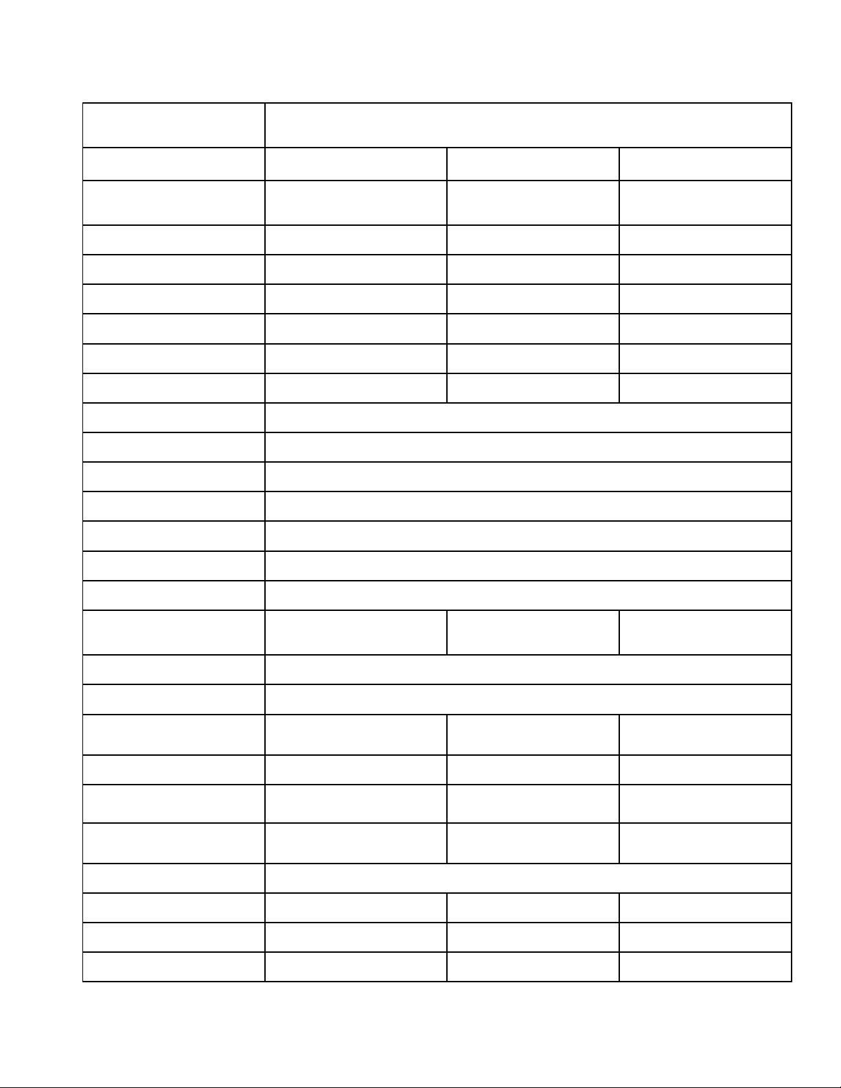
4) MAIN COMPONENTS - MERCHANDISERS
Ballast Name
DY232 IS120
32W × 1EA
B232I120RH-A
17W/32W
B232I120RH-A
32W × 2EA
32W(Double)×1EA /
4) MAIN COMPONENTS - MERCHANDISERS
4) MAIN COMPONENTS - MERCHANDISERS4) MAIN COMPONENTS - MERCHANDISERS
PRODUCT
MODEL
Compressor
(Manufacture)
Compressor Capacity(kcal/h)
Type of Compressor motor
Compressor O.L.P
Compressor Relay
Starting Capacitor
Running Capacitor
Type of Evaporator
Evaporator pipe Dimensions
Cooling Fan Motor
Type of Condenser
MERCHANDISERS
SK182C-L2U
(SAMSUNG)
LBP 256 LBP 1946
RSCR CSIR
4TM444NHBYY
J531Q32E4R7M1802
-
12㎌/250V -
IS3225LTSA, 120V/60Hz
CAJ4476Y(A)
(Tecumseh)
CRA38014
GE3ARR3
250㎌/160V
Cu pipe + Al fin
1/2"
Cu pipe + Al fin
GR70HGR48SGR26H
CAJ4476Y(A)
(Tecumseh)
HBP 1946
CSIR
CRA38014
3ARR3*2M*
250㎌/160V
-
Condenser pipe Dimensions
Condenser Fan Motor
Drier
Temperature Control
Running Indication
Interior Temp. Indication
Interior Lamp
Ad. Panel Fluorescent Lamp
Ballast
(Manufacture)
Defrost for evaporator
Defrost sheath heater
Thermostat
GNF-250L
(Fluorescent lamp)
32W × 1EA
17W×1EA
(ADVANCE)
-
3/8"
MA7425W1, 120V/60Hz
OD 1", XH-9, 1.06oz
Thermostat
(GNF-240L)
-
-
(Fluorescent lamp)
32W × 1EA
32W(Double)×1EA
(ADVANCE)
Off cycle
-
Thermostat
(GNF-246L)
(Fluorescent lamp)
32W × 1EA
32W(Double)×2EA
(DOYOUNG)
-
Defrost pan heater
Drain heater
-
-
-
-
-
-
-A5 -
Page 7
2. REFRIGERATION CYCLE
2. REFRIGERATION CYCLE
2. REFRIGERATION CYCLE 2. REFRIGERATION CYCLE
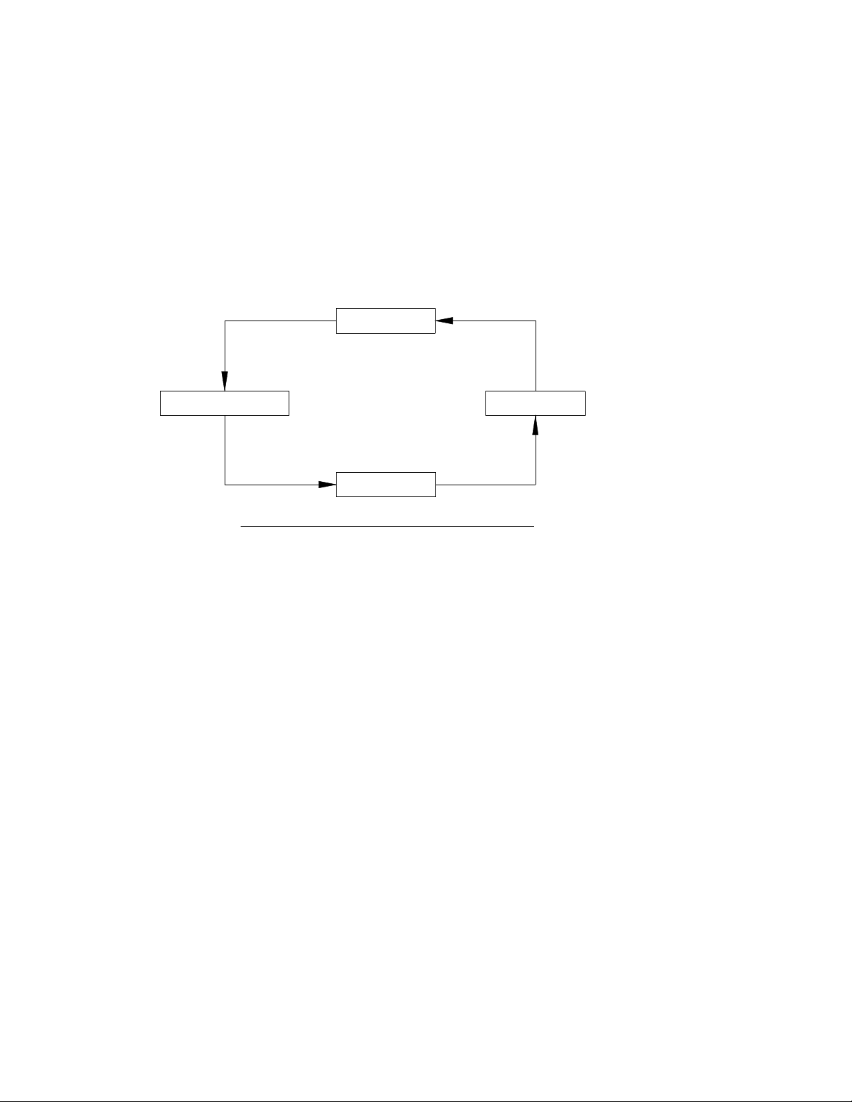
Mechanical refrigeration is accomplished by continuously circulating, evaporating, and condensing
a fixed supply of refrigerant in a closed system. Evaporation occurs at a low temperature and
pressure while condensation occurs at high temperature and pressure. Thus it is possible to
transfer heat from an area of low temperature(i.e., refrigerated compartment) to an area of high
temperature(i.e., surrounding of refrigerator).
CONDENSER
COMPRSSORCAPI LLARY TUBE
EVAPORATOR
THE BASE REFRIGERATION CYCLE
THE BASE REFRIGERATION CYCLE
THE BASE REFRIGERATION CYCLETHE BASE REFRIGERATION CYCLE
Beginning the cycle at the evaporator inlet the low pressure liquid expands, absorbs heat
(so refrigerator inner-cabinet is cooled), and evaporates, changing to a low pressure gas at the
evaporator outlet.
The compressor pumps this gas from the evaporator, increases its pressure, and discharges the
high pressured- temperature gas to the condenser.
The condenser lets high pressured- temperature gas emit the heat(so surrounding of the
condenser is warmed) in order to make it condense.
The capillary tube prevents high pressured- temperature gas from entering the evaporator
in order to lower the pressure in the evaporator and control the flow of refrigerant into the
evaporator automatically.
Eventually the desired air temperature in refrigerator inner-cabinet is reached, the thermostat
(temperature controller) will break the electrical circuit to the compressor motor and stop
the compressor.
-A6 -
Page 8
As the temperature of the air rises, the thermostat(or controller) remakes the electrical circuit.
SUCTION PIPE (INNER-CABINET)
The compressor starts, and cycle continues.
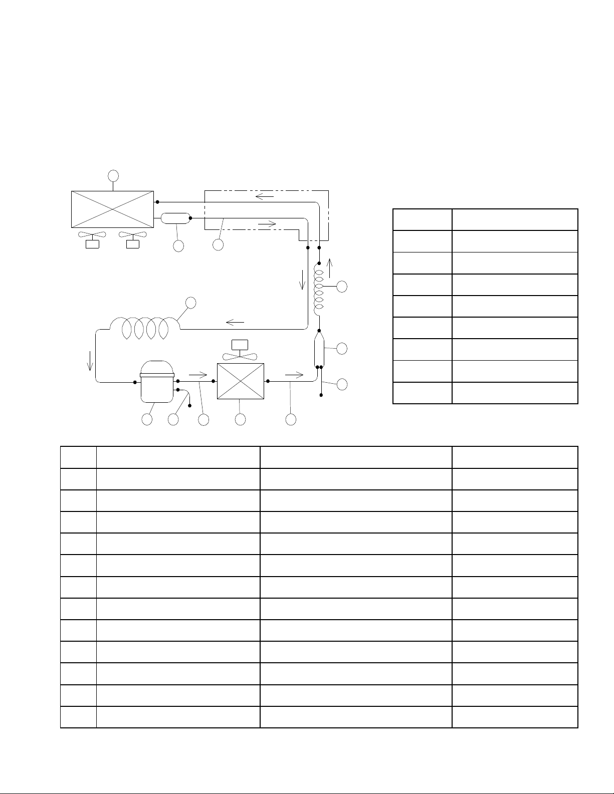
The schematic refrigeration(or freezing) cycle of F23/F49/F72/R23/R49/R72/GR26/GR48/GR70
is like below.
3
Heat Exchange
10
9
6
2
7
5
11
1
No.
COMPRESSOR
1
CONDENSER C1220TS-O,H
2
Part Name Description
12
MODEL
F23
F49
8
F72
R23/R49
R72
4
GR26H
GR48S
GR70H
COMPRESSOR
CAE2420Z(A)
CAJ2432Z(A)
CAJ2446Z(H)
SK6A1C-H2Y
CAJ4461Y(A)
SK182C-L2U
CAJ4476Y(A)
CAJ4476Y(A)
Remark
EVAPORATOR C1220TS-O,H
3
DRIER C1220T-H
4
ACCUMULATOR C1220T-1/4H
5
DISCHARGE PIPE C1220T-O
6
DRIER CONNECT PIPE C1220T-O
7
CAPILLARY TUBE C1220T-H
8
9
SUCTION PIPE (COMPRESSOR) C1220T-O
10
CHARGE PIPE (COMPRESSOR) C1220T-O
11
CHARGE PIPE (DRIER) C1220T-O
12
C1220T-O
-A7 -
Page 9
3. TROUBLESHOOTING
3. TROUBLESHOOTING
3. TROUBLESHOOTING 3. TROUBLESHOOTING
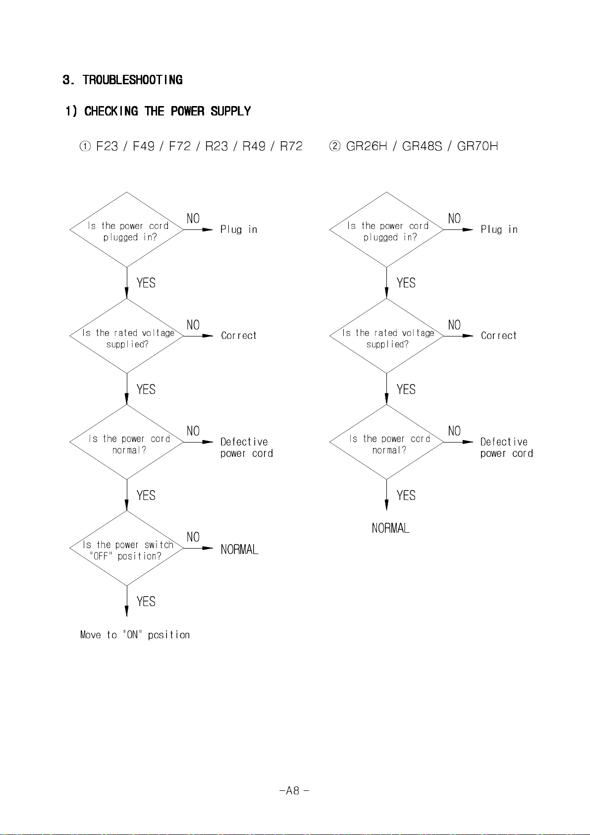
1) CHECKING THE POWER SUPPLY
1) CHECKING THE POWER SUPPLY
1) CHECKING THE POWER SUPPLY
1) CHECKING THE POWER SUPPLY1) CHECKING THE POWER SUPPLY
① F23 / F49 / F72 / R23 / R49 / R72
① BASF1/BASF2/BASF3/BASR3 Models ② BASR1/BASR2/BAGR72 Models
Is the power cord
plugged in?
NO
Plug in
YES
Is the rated voltage
supplied?
NO
Correct
YES
Is the power cord
normal?
NO
Defective
power cord
② GR26H / GR48S / GR70H
Is the power cord
plugged in?
NO
Plug in
YES
Is the rated voltage
supplied?
NO
Correct
YES
Is the power cord
normal?
NO
Defective
power cord
YES
Is the power switch
"OFF" position?
YES
Move to "ON" position
YES
NORMAL
NO
NORMAL
-A8 -
Page 10
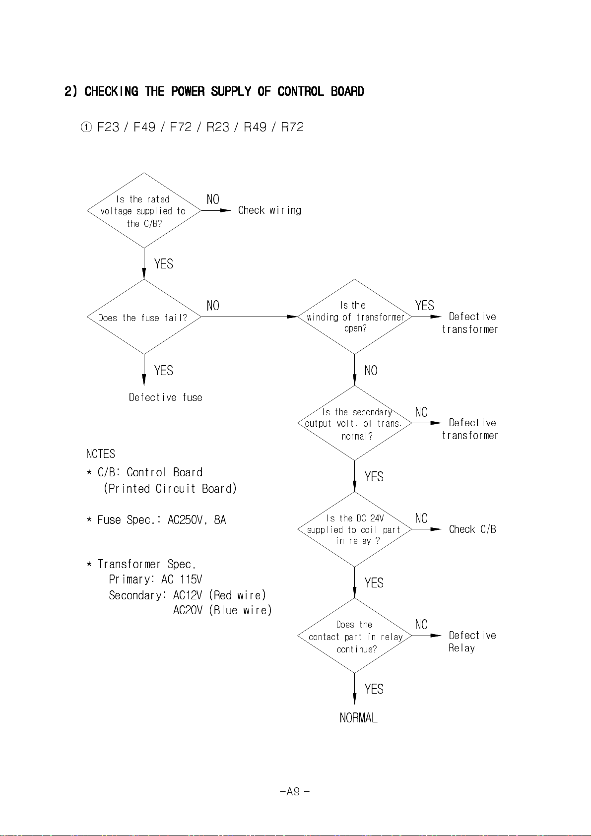
2) CHECKING THE POWER SUPPLY OF CONTROL BOARD
Secondary: AC12V (Red wire)
Primary: AC 115V
Is the
2) CHECKING THE POWER SUPPLY OF CONTROL BOARD
2) CHECKING THE POWER SUPPLY OF CONTROL BOARD
2) CHECKING THE POWER SUPPLY OF CONTROL BOARD2) CHECKING THE POWER SUPPLY OF CONTROL BOARD
① F23 / F49 / F72 / R23 / R49 / R72
① BASF1/BASF2/BASF3/BASR3 Models
Is the rated
voltage supplied to
the C/B?
YES
Does the fuse fail?
YES
Defective fuse
NOTES
* C/B: Control Board
NO
NO
Check wiring
Does the coil
winding of transformer
open?
NO
Is the secondary
output volt. of trans.
normal?
YES
YES
Defective
transformer
NO
Defective
transformer
* Fuse Spec.: AC250V, 8A
(BASF1/BASF2/BASR3)
* Transformer Spec.
AC20V (Blue wire)
Is the DC 24V
supplied to coil part
in relay ?
Does the
contact part in relay
continue?
-A9 -
NO
Check C/B
YES
NO
Defective
Relay
YES
NORMAL
Page 11
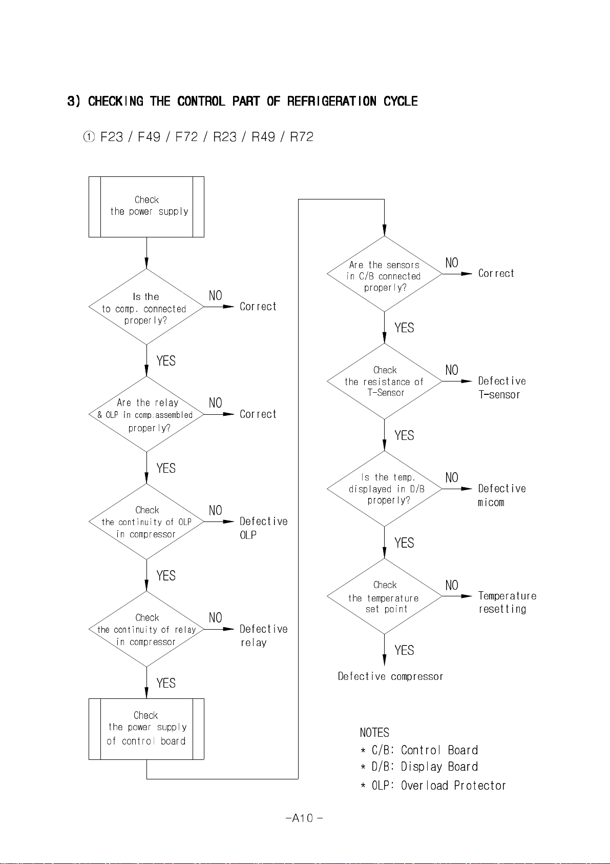
3) CHECKING THE CONTROL PART OF REFRIGERATION CYCLE
3) CHECKING THE CONTROL PART OF REFRIGERATION CYCLE
3) CHECKING THE CONTROL PART OF REFRIGERATION CYCLE3) CHECKING THE CONTROL PART OF REFRIGERATION CYCLE
3) CHECKING THE CONTROL PART OF REFRIGERATION CYCLE
① F23 / F49 / F72 / R23 / R49 / R72
① BASF1/BASF2/BASF3/BASR3 Models
Check
the power supply
Is the
Does the wiring
to comp. connected
properly?
YES
Are the relay
& OLP in comp.assembled
properly?
YES
Check
the continuity of OLP
in compressor
NO
NO
NO
Correct
Correct
Defective
OLP
Are the sensors
in C/B connected
properly?
YES
Check
the resistance of
T-Sensor
YES
Is the temp.
displayed in D/B
properly?
YES
NO
Correct
NO
Defective
T-sensor
NO
Defective
micom
YES
Check
the continuity of relay
in compressor
YES
Check
the power supply
of control board
NO
Defective
relay
-A10 -
Check
the temperature
set point
NO
YES
Defective compressor
NOTES
* C/B: Control Board
* D/B: Display Board
* OLP: Overload Protector
Temperature
resetting
Page 12
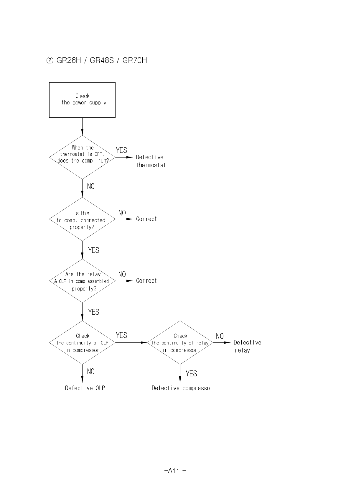
② BASR1/BASR2/BAGR72 Models
Is the
② GR26H / GR48S / GR70H
Check
the power supply
When the
thermoatat is OFF,
does the comp. run?
NO
Does the wiring
to comp. connected
properly?
YES
Are the relay
& OLP in comp.assembled
properly?
YES
YES
Defective
thermostat
NO
Correct
NO
Correct
Check
the continuity of OLP
in compressor
NO
Defective OLP
YES
Check
the continuity of relay
in compressor
YES
Defective compressor
-A11 -
NO
Defective
relay
Page 13
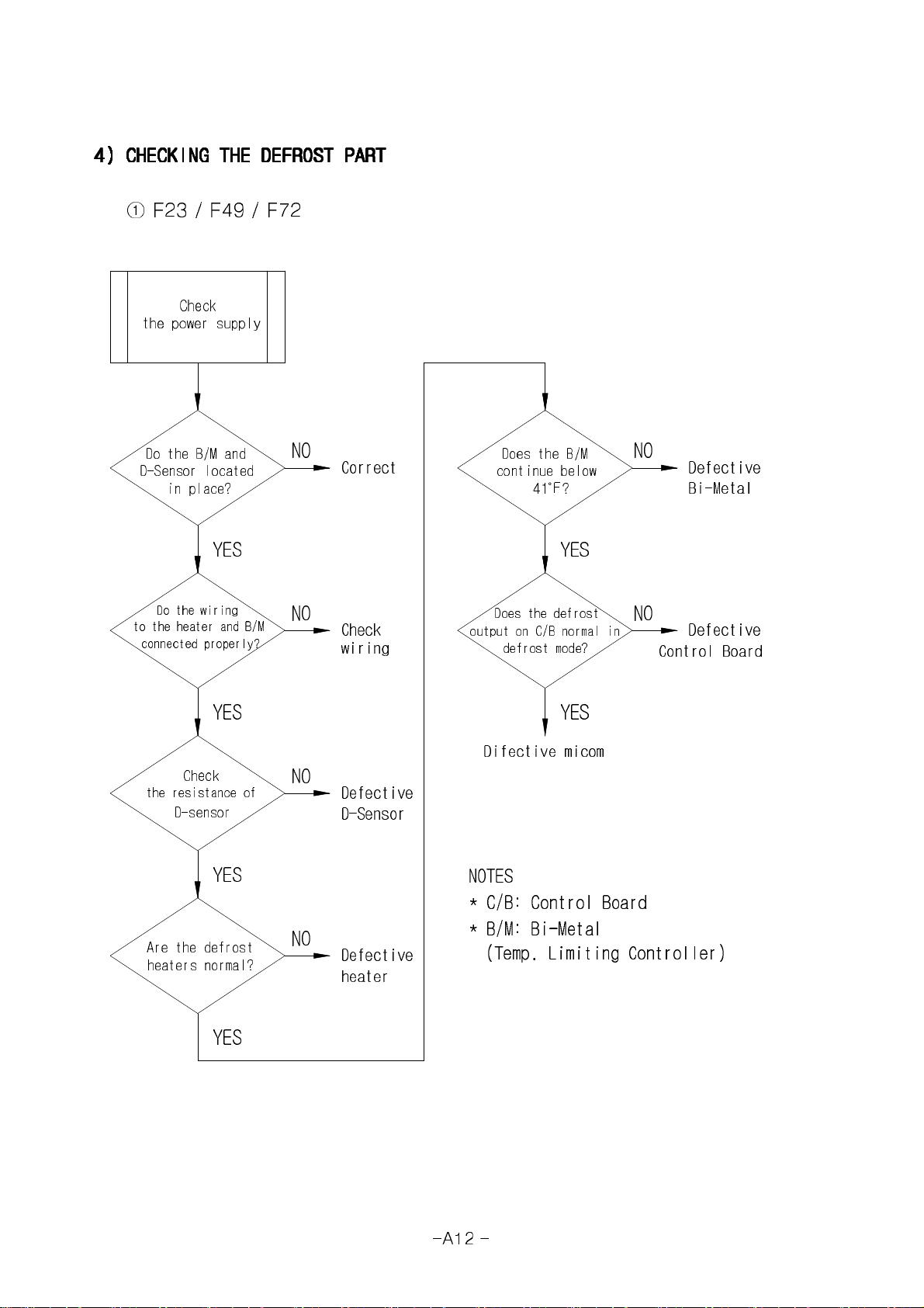
4) CHECKING THE DEFROST PART
4) CHECKING THE DEFROST PART
4) CHECKING THE DEFROST PART4) CHECKING THE DEFROST PART
4) CHECKING THE DEFROST PART
① F23 / F49 / F72
① BASF1/BASF2/BASF3 Models
Check
the power supply
Do the B/M and
D-Sensor located
in place?
YES
Do the wiring
to the heater and B/M
connected properly?
YES
Check
the resistance of
D-sensor
YES
NO
NO
NO
Correct
Check
wiring
Defective
D-Sensor
Does the B/M
continue below
41℉?
YES
Does the defrost
output on C/B normal in
defrost mode?
YES
Difective micom
NOTES
NO
Defective
Bi-Metal
NO
Defective
Control Board
Are the defrost
heaters normal?
YES
NO
Defective
heater
* C/B: Control Board
* B/M: Bi-Metal
(Temp. Limiting Controller)
-A12 -
Page 14
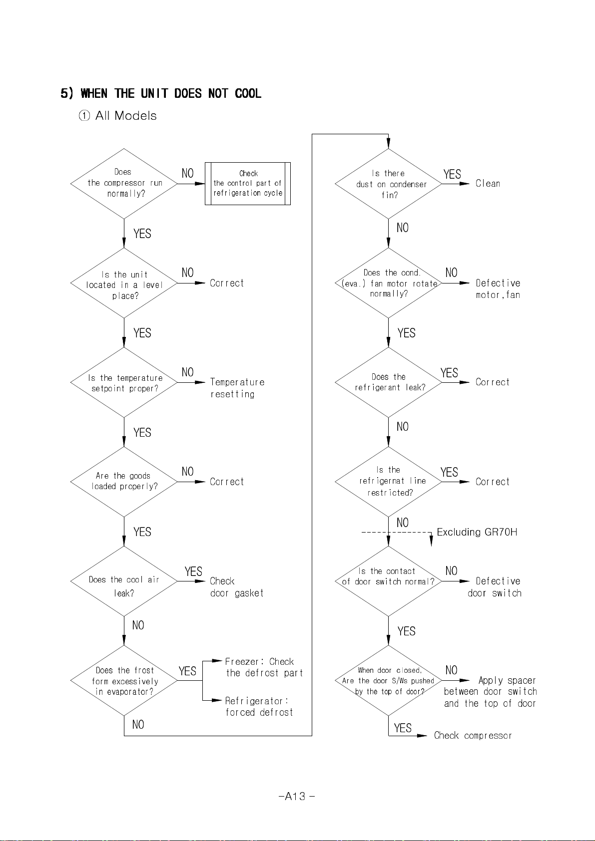
5) WHEN THE UNIT DOES NOT COOL
5) WHEN THE UNIT DOES NOT COOL
5) WHEN THE UNIT DOES NOT COOL
5) WHEN THE UNIT DOES NOT COOL5) WHEN THE UNIT DOES NOT COOL
① All Models
① BASF1/BASF2/BASF3/BASR1/BASR2/BASR3/BAGR72 Models
Does
the compressor run
normally?
YES
Is the unit
located in a level
place?
YES
Is the temperature
setpoint proper?
YES
NO
NO
NO
Check
the control part of
refrigeration cycle
Correct
Temperature
resetting
Is there
dust on condenser
fin?
NO
Does the cond.
(eva.) fan motor rotate
normally?
YES
Does the
refrigerant leak?
NO
YES
Clean
NO
Defective
motor,fan
YES
Correct
Are the goods
loaded properly?
YES
Does the cool air
leak?
NO
Does the frost
form excessively
in evaporator?
NO
NO
YES
YES
Correct
Check
door gasket
Freezer: Check
the defrost part
Refrigerator:
forced defrost
Is the
refrigernat line
restricted?
NO
Is the contact
of door switch normal?
YES
When door closed,
Are the door S/Ws pushed
by the top of door?
YES
YES
Correct
Excluding GR70H
Excluding BAGR72
NO
Defective
door switch
NO
Apply spacer
between door switch
and the top of door
Check compressor
-A13 -
Page 15
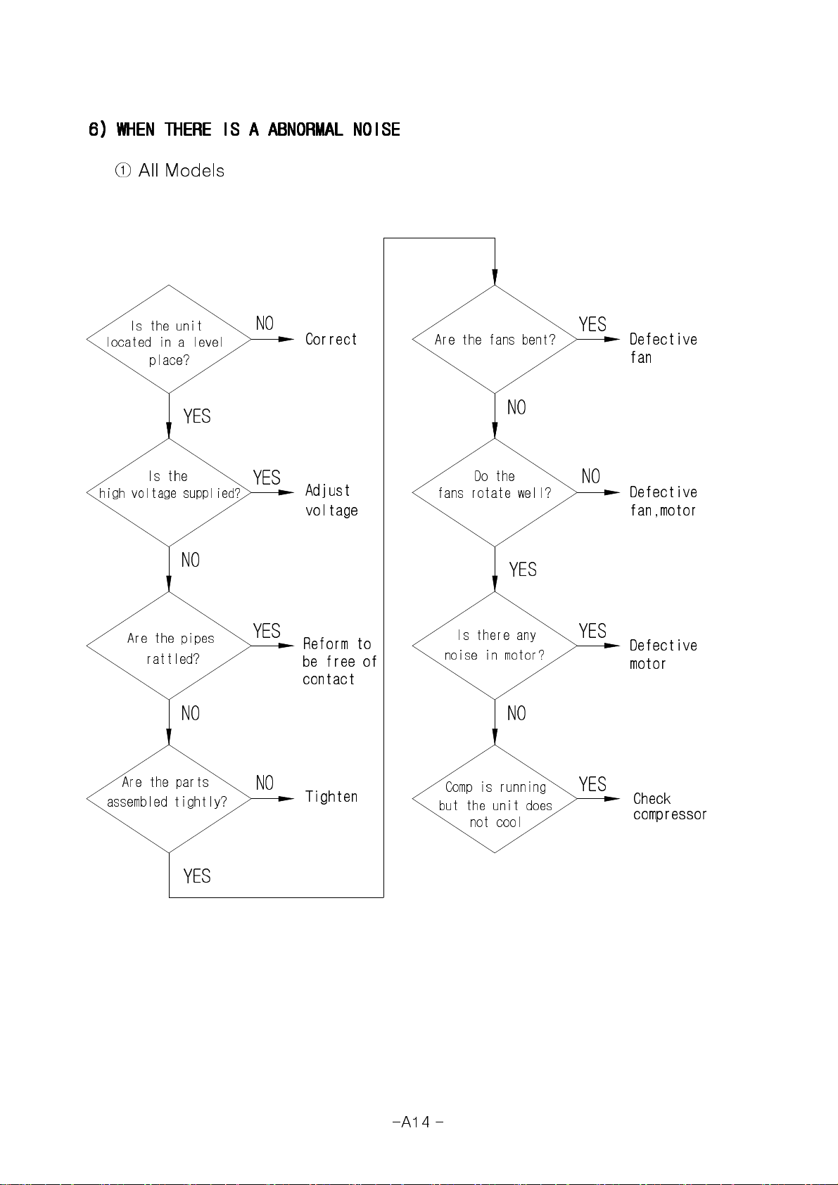
6) WHEN THERE IS A ABNORMAL NOISE
6) WHEN THERE IS A ABNORMAL NOISE
6) WHEN THERE IS A ABNORMAL NOISE6) WHEN THERE IS A ABNORMAL NOISE
6) WHEN THERE IS A ABNORMAL NOISE
① All Models
① BASF1/BASF2/BASF3/BASR1/BASR2/BASR3/BAGR72 Models
Is the unit
located in a level
place?
YES
Is the
high voltage supplied?
NO
Are the pipes
rattled?
NO
NO
YES
YES
Correct
Adjust
Reform to
be free of
contact
Are the fans bent?
NO
Do the
fans rotate well?
YES
Is there any
noise in motor?
NO
YES
Defective
fan
NO
Defective
fan,motorvoltage
YES
Defective
motor
Are the parts
assembled tightly?
YES
NO
Tighten
-A14 -
Comp is running
but the unit does
not cool
YES
Check
compressor
Page 16
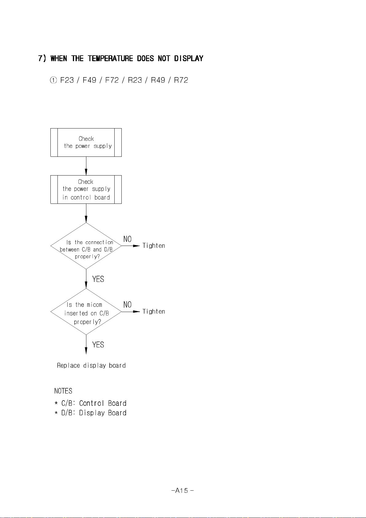
7) WHEN THE TEMPERATURE DOES NOT DISPLAY
Is
7) WHEN THE TEMPERATURE DOES NOT DISPLAY
7) WHEN THE TEMPERATURE DOES NOT DISPLAY
7) WHEN THE TEMPERATURE DOES NOT DISPLAY7) WHEN THE TEMPERATURE DOES NOT DISPLAY
① F23 / F49 / F72 / R23 / R49 / R72
① BASF1/BASF2/BASF3/BASR3 Models
Check
the power supply
Check
the power supply
in control board
Does the connection
between C/B and D/B
properly?
NO
YES
Is the micom
inserted on C/B
properly?
NO
YES
Replace display board
NOTES
* C/B: Control Board
* D/B: Display Board
Tighten
Tighten
-A15 -
Page 17
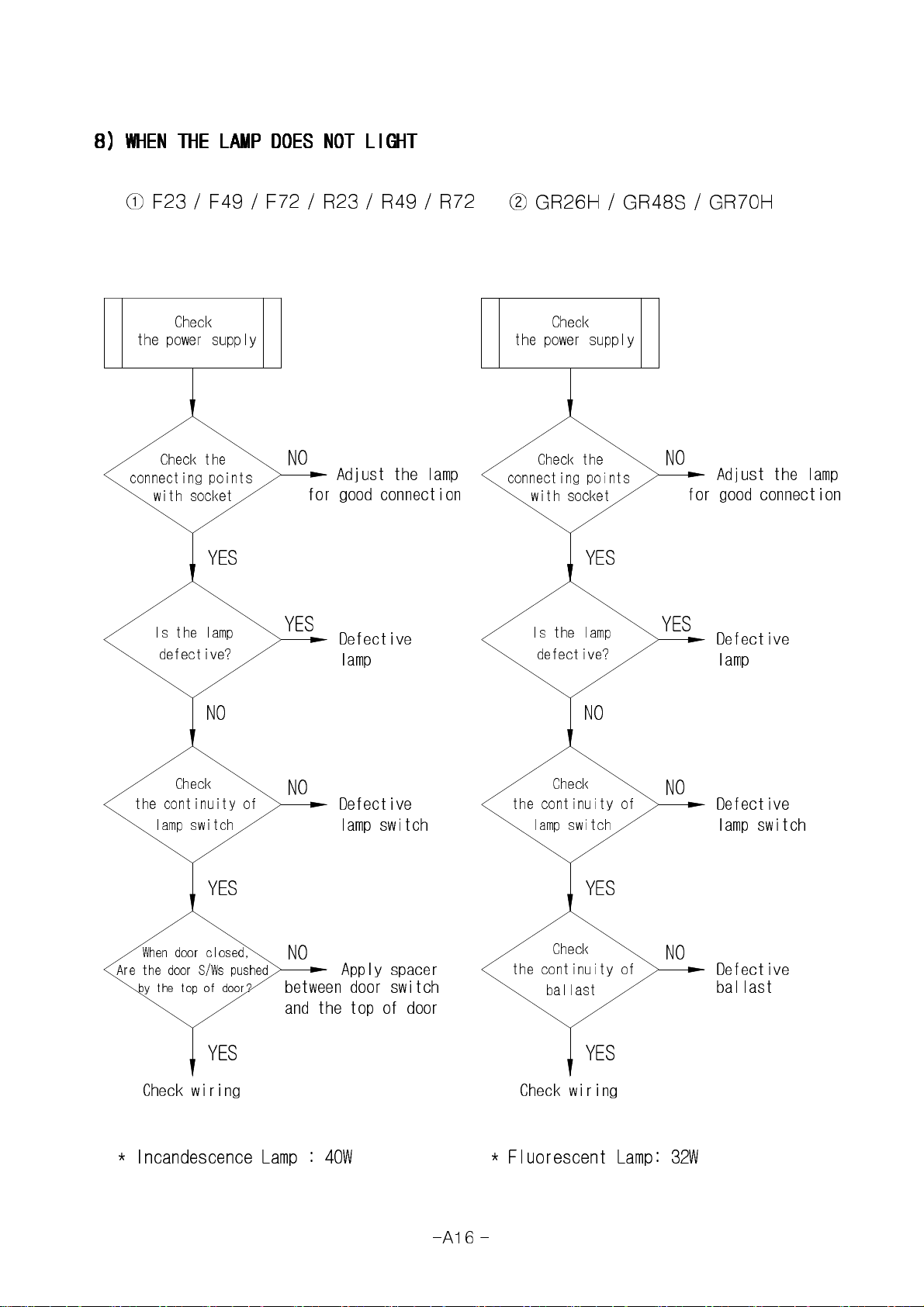
8) WHEN THE LAMP DOES NOT LIGHT
8) WHEN THE LAMP DOES NOT LIGHT
8) WHEN THE LAMP DOES NOT LIGHT8) WHEN THE LAMP DOES NOT LIGHT
8) WHEN THE LAMP DOES NOT LIGHT
① BASF1/BASF2/BASF3 Models ② BAGR72 Model
① F23 / F49 / F72 / R23 / R49 / R72
② GR26H / GR48S / GR70H
BASR1/BASR2/BASR3 Models
Check
the power supply
Check the
connecting points
with socket
YES
Is the lamp
defective?
NO
NO
Adjust the lamp
for good connection
YES
Defective
lamp
Check
the power supply
Check the
connecting points
with socket
YES
Is the lamp
defective?
NO
NO
Adjust the lamp
for good connection
YES
Defective
lamp
Check
the continuity of
lamp switch
NO
Defective
lamp switch
the continuity of
lamp switch
YES
When door closed,
Are the door S/Ws pushed
by the top of door?
NO
Apply spacer
between door switch
and the top of door
the continuity of
ballast
YES YES
Check wiring Check wiring
* Incandescence Lamp : 40W
* Fluorescent Lamp: 32W
Check
Check
NO
Defective
lamp switch
YES
NO
Defective
ballast
-A16 -
Page 18
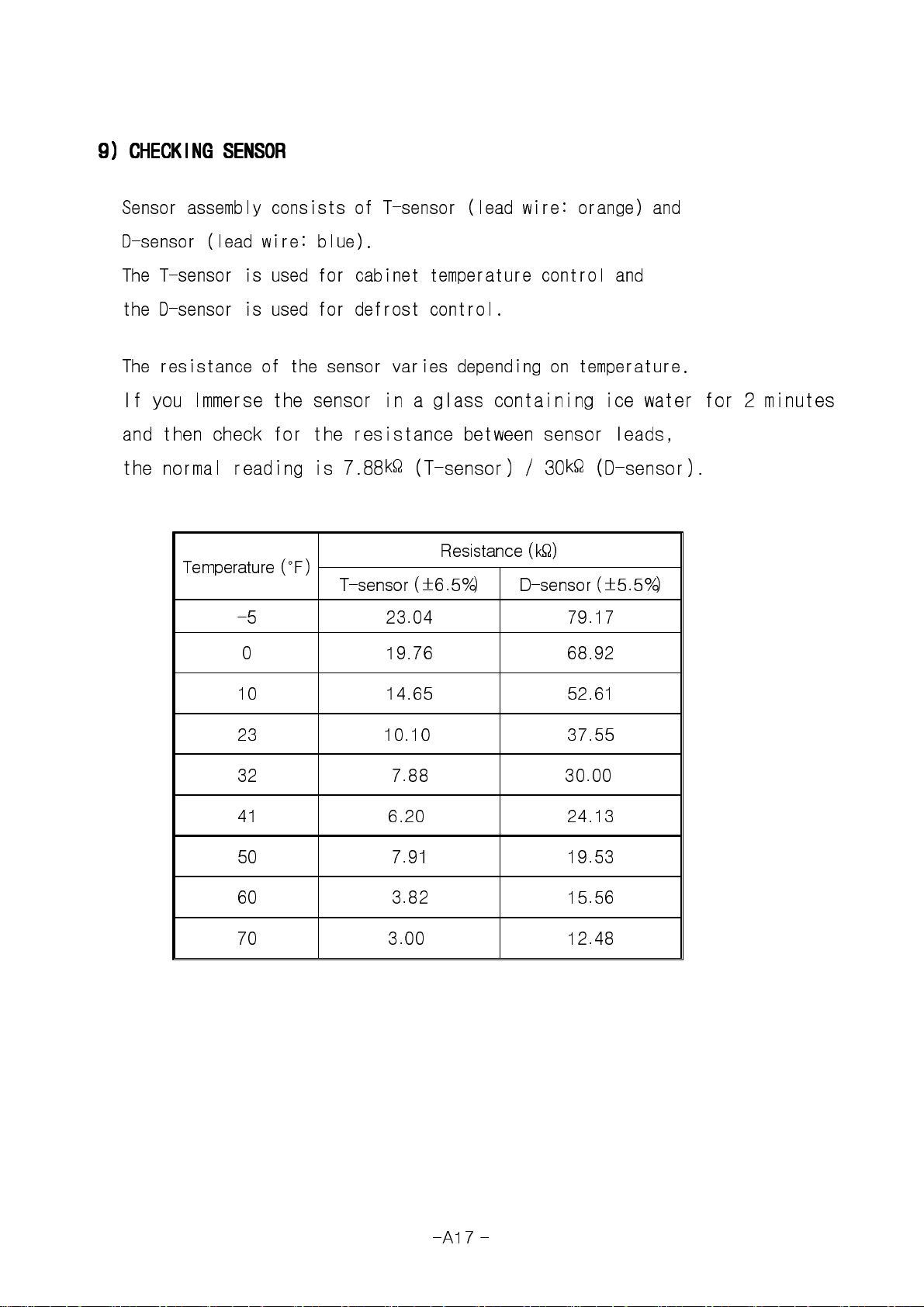
9) CHECKING SENSOR
9) CHECKING SENSOR
9) CHECKING SENSOR 9) CHECKING SENSOR
Sensor assembly consists of T-sensor (lead wire: orange) and
D-sensor (lead wire: blue).
The T-sensor is used for cabinet temperature control and
the D-sensor is used for defrost control.
The resistance of the sensor varies depending on temperature.
If you Immerse the sensor in a glass containing ice water for 2 minutes
and then check for the resistance between sensor leads,
the normal reading is 7.88㏀ (T-sensor) / 30㏀ (D-sensor).
Resistance (㏀)
Temperature (℉)
T-sensor (±6.5%) D-sensor (±5.5%)
-5 23.04 79.17
0 19.76 68.92
10 14.65 52.61
23 10.10 37.55
32 7.88 30.00
41 6.20 24.13
50 7.91 19.53
60 3.82 15.56
70 3.00 12.48
-A17 -
Page 19
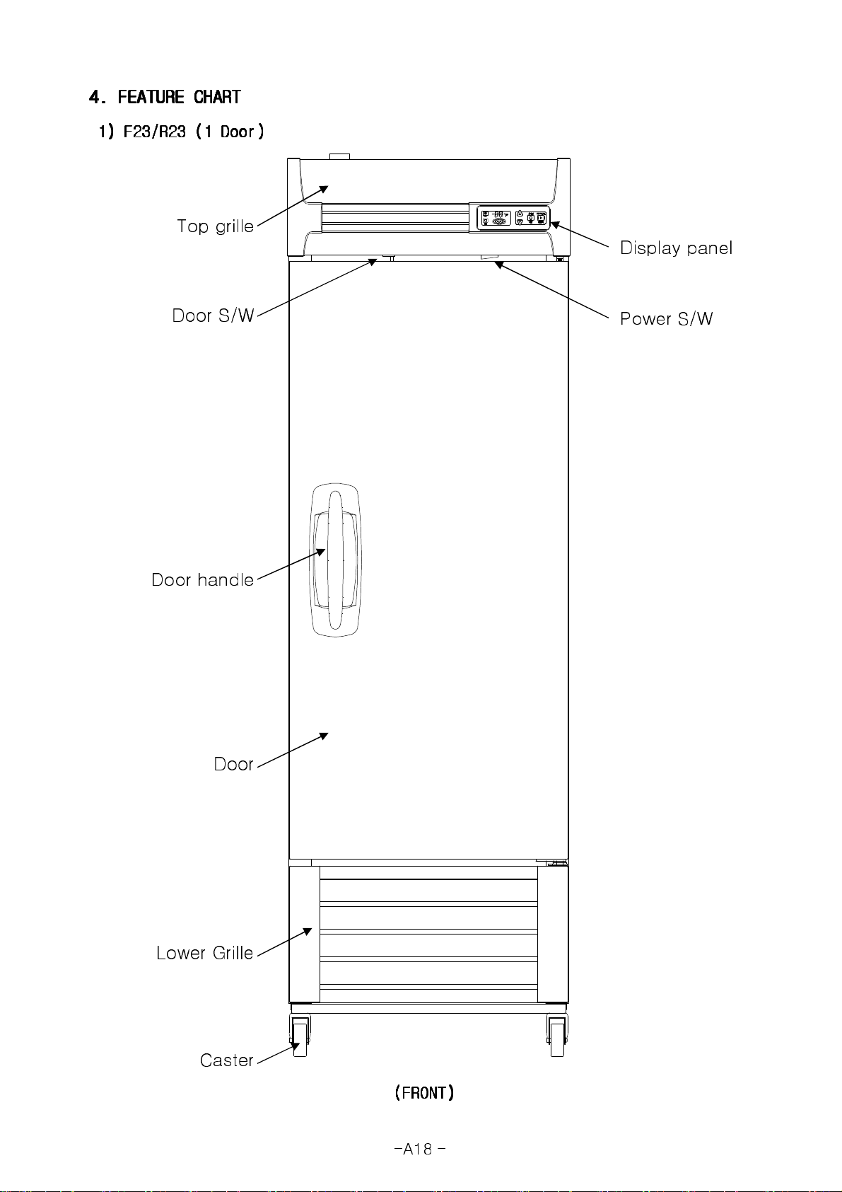
4. FEATURE CHART
4. FEATURE CHART
4. FEATURE CHART 4. FEATURE CHART
1) F23/R23 (1 Door)
1) F23/R23 (1 Door)
1) F23/R23 (1 Door) 1) F23/R23 (1 Door)
Top grille
Display panel
Door S/W
Door handle
Power S/W
Door
Lower Grille
Caster
(FRONT)
(FRONT)
(FRONT) (FRONT)
-A18 -
Page 20
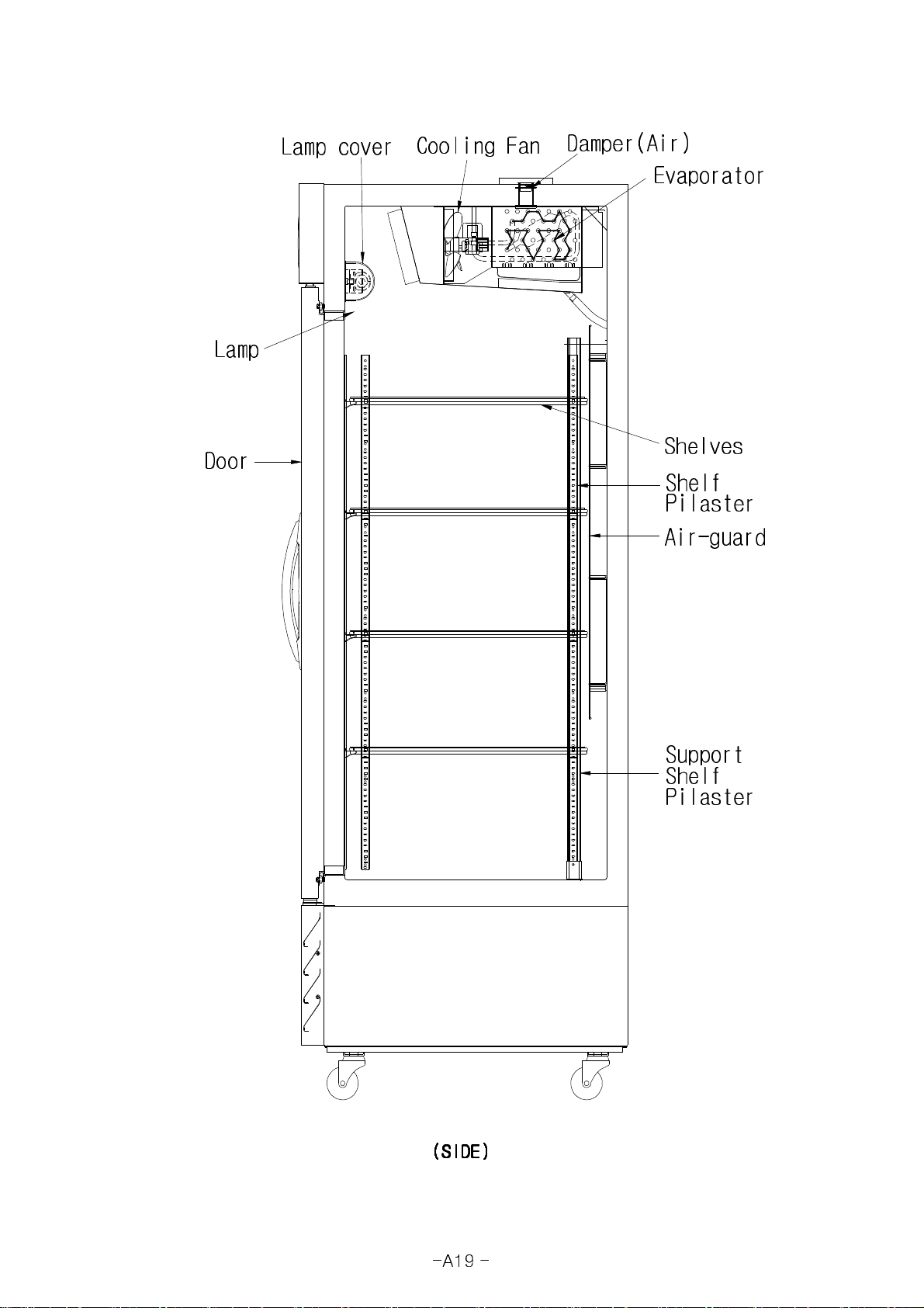
Lamp
Lamp cover
Cooling Fan
Damper(Air)
Evaporator
Door
Shelves
Shelf
Pilaster
Air-guard
Support
Shelf
Pilaster
(SIDE)
(SIDE)
(SIDE) (SIDE)
-A19 -
Page 21
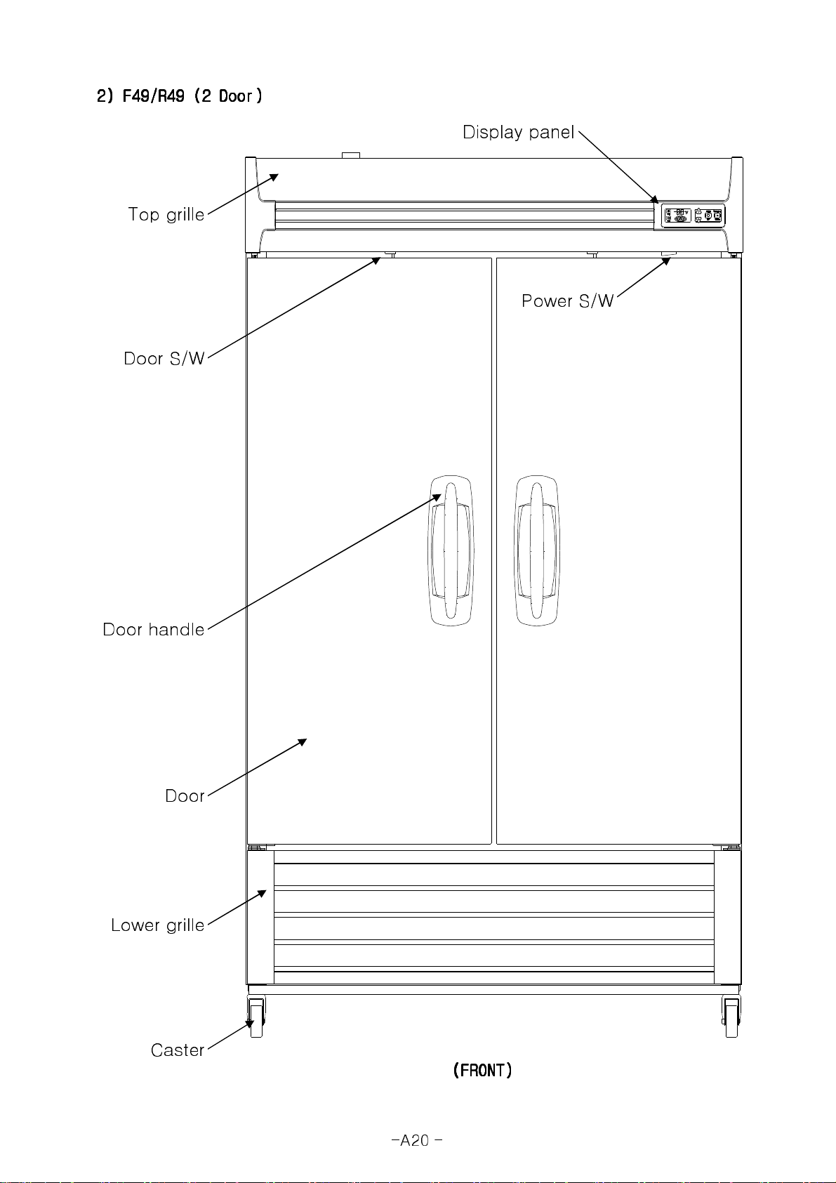
2) F49/R49 (2 Door)
2) F49/R49 (2 Door)
2) F49/R49 (2 Door) 2) F49/R49 (2 Door)
Top grille
Door S/W
Display panel
Power S/W
Door handle
Door
Lower grille
Caster
(FRONT)
(FRONT)
(FRONT) (FRONT)
-A20 -
Page 22
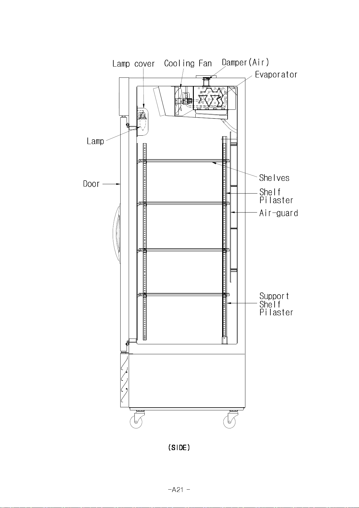
Lamp
Lamp cover
Cooling Fan
Damper(Air)
Evaporator
Door
Shelves
Shelf
Pilaster
Air-guard
Support
Shelf
Pilaster
(SIDE)
(SIDE)
(SIDE) (SIDE)
-A21 -
Page 23

3) F72/R72 (3 Door)
3) F72/R72 (3 Door)
3) F72/R72 (3 Door) 3) F72/R72 (3 Door)
Top grille
Door S/W
Display panel
Power S/W
Lower grille
Door handle
Door
Caster
(FRONT)
(FRONT)
(FRONT) (FRONT)
-A22 -
Page 24

Lamp
Lamp cover
Cooling Fan
Damper(Air)
Evaporator
Door
Shelves
Shelf
Pilaster
Air-guard
Support
Shelf
Pilaster
(SIDE)
(SIDE)
(SIDE) (SIDE)
-A23 -
Page 25

4) GR26H (Glass 1 Door)
4) GR26H (Glass 1 Door)
4) GR26H (Glass 1 Door) 4) GR26H (Glass 1 Door)
AD. Panel
Door(Glass)
Door
Lower grille
Adjust foot
(FRONT)
(FRONT)
(FRONT) (FRONT)
-A24 -
Page 26

BALLAST
AD. PANEL
LAMP
FAN COVER
COOLING FAN
COOLING FAN MOTOR
EVAPORATOR
COVER LAMP
DOOR FRAME
LAMP
DOOR HANDLE
WATER COLLECTOR
DRAIN HOSE
SHELF SUPPORT
SHELF
LOWER GRILLE
CONDENSER
CONDENSER FAN MOTOR
MOTOR BRKT
(SIDE)
(SIDE)
(SIDE) (SIDE)
-A25 -
DRYER
SUCTION PIPE
COMPRESSOR
Page 27

5) GR48S (Glass 2 Door)
5) GR48S (Glass 2 Door)
5) GR48S (Glass 2 Door) 5) GR48S (Glass 2 Door)
Door(Glass)
AD. Panel
Door handle
Lower grille
(FRONT)
(FRONT)
(FRONT) (FRONT)
-A26 -
Adjust foot
Page 28

COOLING FAN COVER
COOLING FAN
BALLAST
AD. PANEL
LAMP
LAMP
LAMP TUBE
DOOR HANDLE
COOLING FAN MOTOR
EVAPORATOR
WATER COLLECTOR
DRAIN HOSE
SHELF SUPPORT
SHELF
DOOR FRAME
CENTER POST
LOWER GRILL
CONDENSER
CONDENSER FAN MOTOR
DRIER
SUCTION PIPE
COMPRESSOR
MOTOR BRKT
(SIDE)
(SIDE)
(SIDE) (SIDE)
-A27 -
Page 29

6) GR70H (Glass 3 Door)
6) GR70H (Glass 3 Door)
6) GR70H (Glass 3 Door) 6) GR70H (Glass 3 Door)
Door(Glass)
AD. Panel
Door handle
Lower grille
Adjust foot
(FRONT)
(FRONT)
(FRONT) (FRONT)
-A28 -
Page 30

Lamp
Door(Glass)
Evaporator Fan Motor
Evaporator
Shelves
Shelf
Pilaster
Door handle
Support
Shelf
Pilaster
(SIDE)
(SIDE)
(SIDE) (SIDE)
-A29 -
Page 31

5. WIRING DIAGRAMS
5. WIRING DIAGRAMS
5. WIRING DIAGRAMS 5. WIRING DIAGRAMS
1) F23
1) F23
1) F23 1) F23
2) F49
2) F49
2) F49 2) F49
-A30 -
Page 32

3) F72
3) F72
3) F72 3) F72
4) R23
4) R23
4) R23 4) R23
-A31 -
Page 33

5) R49
5) R49
5) R49 5) R49
6) R72
6) R72
6) R72 6) R72
-A32 -
Page 34

7) GR26H
7) GR26H
7) GR26H 7) GR26H
8) GR48S
8) GR48S
8) GR48S 8) GR48S
-A33 -
Page 35

9) GR70H
9) GR70H
9) GR70H 9) GR70H
-A34 -
Page 36

6. REPLACEMENT OF COMPONENTS
6. REPLACEMENT OF COMPONENTS
6. REPLACEMENT OF COMPONENTS 6. REPLACEMENT OF COMPONENTS
1) CONDENSING UNIT
1) CONDENSING UNIT
1) CONDENSING UNIT 1) CONDENSING UNIT
(F49/F72/R49/R72)
(F49/F72/R49/R72) (F23/R23/GR26H)
(F49/F72/R49/R72) (F49/F72/R49/R72)
DisassembleDisassemble
Disassemble
(GR48S/GR70H)
(GR48S/GR70H)
(GR48S/GR70H) (GR48S/GR70H)
(F23/R23/GR26H)
(F23/R23/GR26H) (F23/R23/GR26H)
a) Unplug the power cord before
service.
b) Remove screw securing the
lower grille.
* Remove screw securing the
reinforce angle.
(GR48S/GR70H)
(F49/F72/R49/R72)
(F49/F72/R49/R72) (F23/R23/GR26H)
(F49/F72/R49/R72) (F49/F72/R49/R72)
(F23/R23/GR26H)
(F23/R23/GR26H) (F23/R23/GR26H)
c) Separate the compressor har-
ness out of the terminal block.
d) Remove screws securing the
unit base plate and pull out
condensing unit with care.
e) Replace the necessary com-
(GR48S/GR70H)
(GR48S/GR70H)
※ CAUTION
※ CAUTION
※ CAUTION ※ CAUTION
(GR48S/GR70H) (GR48S/GR70H)
ponent.
1. Please pull out or push in the unit base plate carefully to prevent capillary tube, pipes
and wires from demaging.
2. It is recommend to arrange wires after you push in the unit base plate.
-A35 -
Page 37

2-1) LAMP
) Remove screw securing the Ad. Panel Frame and pull out the Ad. Panel Frame with care.
2-1) LAMP
2-1) LAMP 2-1) LAMP
AD. PANEL
AD. PANEL FRAME
(GR26H)
(GR26H)
(GR26H)(GR26H)
LAMP HOLDER
LAMP CAP
LAMP
a) Unplug the power cord before service.
b
c) Separate the Ad. Panel.
d) Separate the Lamp from the Lamp Holder.
e) Separate the Lamp Cap and replace the Lamp with care.
a) Unplug the power cord before
service.
b) Separate the Lamp from the
LAMP CAP
SOCKET
Lamp Holder.
c) Separate the Lamp Socket and
LAMP COVER
the Cap Lamp.
d) Replace the Lamp with care.
LAMP
LAMP TUBE
♠ Lamp Description : AC115V, F17T8/TL950
♠ Lamp Description : AC115V, F17T8/TL950
♠ Lamp Description : AC115V, F17T8/TL950 ♠ Lamp Description : AC115V, F17T8/TL950
-A36 -
Page 38

2-2) LAMP
2-2) LAMP
2-2) LAMP 2-2) LAMP
(GR48S)
(GR48S)
(GR48S)(GR48S)
LAMP HOLDER
LAMP CAP
1
2
3
4
5
6
7
1
2
LAMP
a) Unplug the power cord before service.
b) Remove screw securing the Ad. Panel Side.
c) Separate the Ad. Panel.
d) Separate the Lamp from the Lamp Holder.
AD. PANEL FRAME SIDE
7
1
2
3
AD. PANEL
e) Separate the Lamp Cap and replace the Lamp with care.
a) Unplug the power cord before
service.
b) Separate the Lamp from the
Lamp Holder.
c) Separate the Lamp Socket and
the Lamp Cap.
d) Replace the Lamp with care.
♠ Lamp Description : AC115V, FHF32SSEX-D-5
♠ Lamp Description : AC115V, FHF32SSEX-D-5
♠ Lamp Description : AC115V, FHF32SSEX-D-5 ♠ Lamp Description : AC115V, FHF32SSEX-D-5
-A37 -
Page 39

2-3) LAMP
2-3) LAMP
2-3) LAMP 2-3) LAMP
(GR70H)
(GR70H)
(GR70H)(GR70H)
Lamp Holder
Ad. Panel Frame (R)
Cap Lamp
a) Unplug the power cord before service.
b) Remove screw securing the Ad. Panel Frame (R).
c) Separate the Ad. Panel.
d) Separate the Lamp from the Lamp Holder.
e) Separate the Cap Lamp and replace the Lamp with care.
Lamp
Ad. Panel
Lamp Cap
Cap Lamp
Thin Screw
Lamp Base
Lamp
Lamp Tube
Socket
♠ Lamp Description : AC115V, 32W, F32T8/TL860
♠ Lamp Description : AC115V, 32W, F32T8/TL860
♠ Lamp Description : AC115V, 32W, F32T8/TL860 ♠ Lamp Description : AC115V, 32W, F32T8/TL860
a) Unplug the power cord before
service.
b) Separate the Lamp from the
Lamp Holder.
c) Separate the Lamp Socket and
the Lamp Cap.
d) Replace the Lamp with care.
-A38 -
Page 40

■ MODEL : F23/F49/F72(FREEZER) R23/R49/R72(REFRIGERATOR)
■ MODEL : F23/F49/F72(FREEZER) R23/R49/R72(REFRIGERATOR)
■ MODEL : F23/F49/F72(FREEZER) R23/R49/R72(REFRIGERATOR) ■ MODEL : F23/F49/F72(FREEZER) R23/R49/R72(REFRIGERATOR)
GR26/GR48/GR70(MERCHANDISERS)
GR26/GR48/GR70(MERCHANDISERS)
GR26/GR48/GR70(MERCHANDISERS) GR26/GR48/GR70(MERCHANDISERS)
B. OPERATION AND ELECTRONIC CONTROLLER FUNCTION
1. OPERATION FOR F23, F49, F72, R23, R49, R72 MODELS - - - - - B2
1. OPERATION FOR F23, F49, F72, R23, R49, R72 MODELS - - - - - B2
1. OPERATION FOR F23, F49, F72, R23, R49, R72 MODELS - - - - - B2 1. OPERATION FOR F23, F49, F72, R23, R49, R72 MODELS - - - - - B2
1) BASIC OPERATION
2) ELECTRONIC CONTROLLER SETING MODE
3) NORMAL CONTROL PROCESS
4) ERROR CODE
2. OPERATION FOR GR26H, GR48S, GR70H MODELS - - - - - - - - - B9
2. OPERATION FOR GR26H, GR48S, GR70H MODELS - - - - - - - - - B9
2. OPERATION FOR GR26H, GR48S, GR70H MODELS - - - - - - - - - B9 2. OPERATION FOR GR26H, GR48S, GR70H MODELS - - - - - - - - - B9
1) BASIC OPERATION
2) ELECTRONIC CONTROLLER SETING MODE
3) NORMAL CONTROL PROCESS
4) ERROR CODE
4. INSTRUCTION FOR RE-HINGING DOOR - - - - - - - - - - - - - B10
4. INSTRUCTION FOR RE-HINGING DOOR - - - - - - - - - - - - - B10
4. INSTRUCTION FOR RE-HINGING DOOR - - - - - - - - - - - - - B10 4. INSTRUCTION FOR RE-HINGING DOOR - - - - - - - - - - - - - B10
....
- B1 -
Page 41

1. OPERATION FOR F23/F49/F72(FREEZER), R23/R49/R72(REFRIGERATOR)
1. OPERATION FOR F23/F49/F72(FREEZER), R23/R49/R72(REFRIGERATOR)
1. OPERATION FOR F23/F49/F72(FREEZER), R23/R49/R72(REFRIGERATOR) 1. OPERATION FOR F23/F49/F72(FREEZER), R23/R49/R72(REFRIGERATOR)
1) BASIC OPERATION
1) BASIC OPERATION
1) BASIC OPERATION 1) BASIC OPERATION
① Plug in the power cord and turn on the power switch located on the bottom of the top grille
right side.
[ The unit should be plugged into a
[ The unit should be plugged into a
② Display panel will be lightened for 2 seconds with buzzer then displays cabinet interior
temperature (T-sensor) and running conditions.
* Freezer : If cabinet interior temperature is higher than 14℉ compressor will run without
delay, and lower than 14℉, compressor will run after 3 minutes.
* Refrigerator : If cabinet interior temperature is higher than 50℉ compressor will run
without delay, and lower than 50℉, compressor will run after 3 minutes.
③ The default OPERATING TEMPERATURE SETTING
* Freezer : Temperature set point (setting mode sign [st]) is –5℉
Temperature differential set point (setting mode sign [di]) is 8℉.
(Operating Temperature : -14℉ ~ -4℉)
Range of adjustable set point: -22℉ ~ 8℉
* Refrigerator : Temperature set point (setting mode sign [st]) is 36℉
115V±10%, 60Hz
115V±10%, 60Hz
115V±10%, 60Hz 115V±10%, 60Hz
115V/208~230V, 60Hz
115V/208~230V, 60Hz
115V/208~230V, 60Hz115V/208~230V, 60Hz
(F23, F49, R23, R49, R72 models) ]
(F72 model) ]
Temperature differential set point (setting mode sign [di]) is 8℉.
(Operating Temperature : 34℉ ~ 44℉)
Range of adjustable set point: 25℉ ~ 50℉
④ Defrost frequency
* Freezer : It is controlled by MICOM and the default defrost frequency is 6 hours.
* Refrigerator : It is controlled by MICOM and the default defrost frequency is 12 hours.
⑤ The light inside the cabinet comes on when the door is opened.
The cabinet interior cooling fan has 3 seconds delay when the door is closed.
⑥ If door is opened, door open warnign sign (LED) will turn on.
If door is opened more than 30 seconds, the sound alarm beeps 3times,
if open more than 60 seconds, the sound alarm beeps 5 times and if open more than 5 minutes,
the sound alarm will beep continuously.
⑦ Cabinet interior temperature
* Freezer : If it is higher than 14℉(F23, F49, F72), the panel displays [Hi] and
- B2 -
Page 42

lower than -50℉(F23, F49, F72), the panel displays [Lo].
* Refrigerator : If it is higher than 68℉(F23, F49, F72), the panel displays [Hi] and
lower than 14℉(F23, F49, F72), the panel displays [Lo].
2) ELECTRONIC CONTROLLER SETTING MODE
2) ELECTRONIC CONTROLLER SETTING MODE
2) ELECTRONIC CONTROLLER SETTING MODE 2) ELECTRONIC CONTROLLER SETTING MODE
- B3 -
Page 43

No Setting Mode
Mode
Sign
How to Setting
Temperature
TemperatureTemperature
1
Temperature
Setting
Setting
SettingSetting
Mode
Mode
ModeMode
"St"
"St"
"St""St"
1. To enter this mode, press
until
2. Then press
[St]
[St]
is displayed.
[St][St]
[MODE/SET]
[MODE/SET]
[MODE/SET][MODE/SET]
3. To change the set point, press
[MODE/SET]
[MODE/SET]
[MODE/SET][MODE/SET]
and
[UP or DOWN]
[UP or DOWN]
[UP or DOWN][UP or DOWN]
to see current temperature set point.
[UP or DOWN]
[UP or DOWN]
[UP or DOWN][UP or DOWN]
until the desired value
is displayed.
4. At the end of the sequence, press
[MODE/SET]
[MODE/SET]
[MODE/SET][MODE/SET]
to set the value.
5. To display the cabinet temperature again, press
[th]
[th]
is displayed and then press
[th][th]
6. Range of adjustable set point :
Range of adjustable set point :
[VERIFY]
[VERIFY]
[VERIFY][VERIFY]
-22℉ to 8℉
-22℉ to 8℉
-22℉ to 8℉ -22℉ to 8℉
25℉ to 50℉
25℉ to 50℉
25℉ to 50℉ 25℉ to 50℉
.
(Freezer)
(Refrigerator)
simultaneously
[UP or DOWN]
[UP or DOWN]
[UP or DOWN][UP or DOWN]
until
Temperature
Temperature
TemperatureTemperature
Differential
Differential
DifferentialDifferential
2
Setting
Setting
SettingSetting
Mode
Mode
ModeMode
"di"
"di"
"di""di"
1. To enter this mode, press
until
2. Then press
[di]
[di]
is displayed.
[di][di]
[MODE/SET]
[MODE/SET]
[MODE/SET][MODE/SET]
3. To change the set point, press
[MODE/SET]
[MODE/SET]
[MODE/SET][MODE/SET]
and
[UP or DOWN]
[UP or DOWN]
[UP or DOWN][UP or DOWN]
to see current temperature differential.
[UP or DOWN]
[UP or DOWN]
[UP or DOWN][UP or DOWN]
until the desired value
is displayed.
4. At the end of the sequence, press
[MODE/SET]
[MODE/SET]
[MODE/SET][MODE/SET]
to set the value.
5. To display the cabinet temperature again, press
[th]
[th]
is displayed and then press
[th][th]
6. Range of adjustable set point :
Range of adjustable set point :
[VERIFY]
[VERIFY]
[VERIFY][VERIFY]
4℉ to 16℉
4℉ to 16℉
4℉ to 16℉4℉ to 16℉
6℉ to 16℉
6℉ to 16℉
6℉ to 16℉6℉ to 16℉
.
(Freezer)
(Refrigerator)
simultaneously
[UP or DOWN]
[UP or DOWN]
[UP or DOWN][UP or DOWN]
until
(The Unit of Setting : 2℉)
- B4 -
Page 44

No Setting Mode
Mode
Sign
How to Setting
3
Defrost
Defrost
DefrostDefrost
Frequency
Frequency
FrequencyFrequency
Setting
Setting
SettingSetting
Mode
Mode
ModeMode
"dt"
"dt"
"dt""dt"
1. To enter this mode, press
until
2. Then press
[dt]
[dt]
is displayed.
[dt][dt]
[MODE/SET]
[MODE/SET]
[MODE/SET][MODE/SET]
3. To change the defrost frequency, press
[MODE/SET]
[MODE/SET]
[MODE/SET][MODE/SET]
and
[UP or DOWN]
[UP or DOWN]
[UP or DOWN][UP or DOWN]
to see current defrost frequency.
[UP or DOWN]
[UP or DOWN]
[UP or DOWN][UP or DOWN]
value is displayed.
4. At the end of the sequence, press
[MODE/SET]
[MODE/SET]
[MODE/SET][MODE/SET]
to set the value.
5. To display the cabinet temperature again, press
[th]
[th]
is displayed and then press
[th][th]
6. Range of adjustable defrost frequency :
[VERIFY]
[VERIFY]
[VERIFY][VERIFY]
.
4Hr to 12Hr
4Hr to 12Hr
4Hr to 12Hr4Hr to 12Hr
(The Unit of frequency : 2Hr)
simultaneously
until the desired
[UP or DOWN]
[UP or DOWN]
[UP or DOWN][UP or DOWN]
until
4
Cancelation
CancelationCancelation
5
6
Forced
Forced
ForcedForced
Defrost
Defrost
DefrostDefrost
Mode
Mode
ModeMode
Cancelation
of
of
ofof
Forced
Forced
ForcedForced
Defrost
Defrost
DefrostDefrost
Mode
Mode
ModeMode
Rapid
Rapid
RapidRapid
Freeze
Freeze
FreezeFreeze
Mode
Mode
ModeMode
(Freezer)
(Freezer)
(Freezer)(Freezer)
"dF"
"dF"
"dF""dF"
Flash
Flash
FlashFlash
"dF"
"dF"
"dF""dF"
"tb"
"tb"
"tb""tb"
1. To enter this mode, press
until
2. Then press
3. During defrosting,
[dF]
[dF]
is displayed.
[dF][dF]
[MANUAL DF]
[MANUAL DF]
[MANUAL DF][MANUAL DF]
[dF]
[dF]
[dF][dF]
1. During forced defrost, press
[MODE/SET]
[MODE/SET]
[MODE/SET][MODE/SET]
more than
and
2 seconds
2 seconds
2 seconds2 seconds
[UP or DOWN]
[UP or DOWN]
[UP or DOWN][UP or DOWN]
simultaneously
to start forced defrost.
is displayed instead of the cabinet temperature.
[MANUAL DF]
[MANUAL DF]
[MANUAL DF][MANUAL DF]
more than
2 seconds to stop forced defrost.
2. The [dF] will be flash 5 times and then return to normal display mode.
1. To enter this mode, press
until
2. Then press
[tb]
[tb]
is displayed.
[tb][tb]
[MODE/SET]
[MODE/SET]
[MODE/SET][MODE/SET]
[MODE/SET]
[MODE/SET]
[MODE/SET][MODE/SET]
more than
and
2 seconds
2 seconds
2 seconds2 seconds
[UP or DOWN]
[UP or DOWN]
[UP or DOWN][UP or DOWN]
simultaneously
to start rapid freeze mode.
3. During rapid freeze,
- B5 -
[tb]
[tb]
is displayed instead of the cabinet temperature.
[tb][tb]
Page 45

No Setting Mode
Mode
Sign
How to Setting
Cancelation of
Cancelation of
Cancelation ofCancelation of
Rapid
Rapid
RapidRapid
Freeze
Freeze
7
8
8
FreezeFreeze
Mode
Mode
ModeMode
(Freezer)
(Freezer)
(Freezer)(Freezer)
Cabinet
Cabinet
CabinetCabinet
Temperature
Temperature
TemperatureTemperature
Verification
Verification
VerificationVerification
Mode
Mode
ModeMode
Cabinet
Cabinet
CabinetCabinet
Temperature
Temperature
TemperatureTemperature
Verification
Verification
VerificationVerification
Mode
Mode
ModeMode
Flash
Flash
FlashFlash
"tb"
"tb"
"tb""tb"
"th"
"th"
"th""th"
"th"
"th"
"th""th"
1. During rapid freeze, press
[MODE/SET]
[MODE/SET]
[MODE/SET][MODE/SET]
more than
2 seconds to stop rapid freeze.
2. The
1. To enter this mode, press
until
2. Then press
[tb]
[tb]
will be flash 5 times and then return to normal display mode.
[tb][tb]
[MODE/SET]
[th]
[th]
is displayed.
[th][th]
[MODE/SET]
[MODE/SET]
[MODE/SET][MODE/SET]
[MODE/SET]
[MODE/SET][MODE/SET]
to see F-sensor, D-sensor temperature in turn.
and
[UP or DOWN]
[UP or DOWN]
[UP or DOWN][UP or DOWN]
simultaneously
3. To check only the F-sensor or D-sensor temperature, press
again.
[MODE/SET]
[MODE/SET]
[MODE/SET][MODE/SET]
4. Press
(return to normal display mode)
3) NORMAL CONTROL PROCESS
3) NORMAL CONTROL PROCESS
3) NORMAL CONTROL PROCESS 3) NORMAL CONTROL PROCESS
No FUNCTION
1. After Power ON, Display panel will be lightened for 2 seconds with buzzer then
1
Initial
Initial
InitialInitial
Operating
Operating
OperatingOperating
displays cabinet interior temperature.
2. If cabinet interior temperature is higher than 14℉, compressor will run
without delay, and lower than 14℉, compressor will run after 3 minutes.
1. Compressor and condenser fan motor is controlled by T-sensor and MICOM program.
displays cabinet interior temperature.
2. Compressor ON/OFF Temperature
Normal
Normal
2
NormalNormal
Operating
Operating
OperatingOperating
Compressor ON : Temperature Setting Value + (Temperature Differential Setting Value/2)
Compressor OFF : Temperature Setting Value - (Temperature Differential Setting Value/2)
[VERIFY]
[VERIFY]
[VERIFY] [VERIFY]
to see current cabinet temperature.
FUNCTION SPEC
ex) st: -9℉, di: 10℉ ⇒ Compressoer ON: -9+(10/2) = -4℉,Compressoer OFF: -9-(10/2) = -14℉
st: 39℉, di: 10℉ ⇒ Compressoer ON: 39+(10/2) = 44℉,Compressoer OFF: 39-(10/2) = 34℉
- B6 -
Page 46

No FUNCTION
It prevent exceed temperature rise during defrosting,
Rapid
Rapid
RapidRapid
3
Freeze
Freeze
FreezeFreeze
(Freezer)
(Freezer)
(Freezer)(Freezer)
FUNCTION SPEC
1. Compressor and cabinet interior cooling fan is running continuously for
120 minutes without control by sensor.
2. It is impossible to set the other modes during Rapid Freeze Mode.
It is necessary to cancel the Rapid Freeze Mode before setting the other modes.
3. If Defrost Mode become in the Rapid Freeze Mode duration,
Defrost Mode will start after the Rapid Freeze Mode finished.
4. Rapid Freeze Mode will be start after Defrost Mode finished not during
Defrost Mode. [tb] is displayed from startng the Rapid Freeze Mode.
1. Defrost process is like below
Process
Process Controlled Part
ProcessProcess
Controlled Part Description
Controlled PartControlled Part
Description
DescriptionDescription
(Freezer)
(Freezer)
(Freezer)(Freezer)
4
(Refrigerator)
(Refrigerator)
(Refrigerator)(Refrigerator)
Defrost
Defrost
DefrostDefrost
Defrost
Defrost
DefrostDefrost
Pre
Pre----Cool
Cool
PrePre
CoolCool
Defrost
Defrost
DefrostDefrost
Pause
Pause
PausePause
Evaporator
Evaporator
Evaporator Evaporator
Fan Delay
Fan Delay
Fan DelayFan Delay
Compressor
Evaporator Fan
Condenser Fan
Defrost Heater
Compressor
Evaporator Fan
Condenser Fan
Defrost Heater
Compressor
Evaporator Fan
Condenser Fan
Defrost Heater
Compressor
Evaporator Fan
Condenser Fan
Defrost Heater
On
On
OnOn
Off
Off
OffOff
Off
Off
OffOff
On
On
OnOn
①
On
On
OnOn
② Cycle is run continuously until current compressor
On
On
OnOn
cut-out temperature reach.
Off
Off
OffOff
③ Maximum time: 30minutes
① Preprogrammed frequency interval
Off
Off
Off Off
② If D-sensor is higher than 50℉, defrost heater off
Off
Off
OffOff
③ Maximum time: 40minutes
On
On
OnOn
OOOOff
ff
ff ff
① Time: 3minutes
Off
Off
OffOff
Off
Off
OffOff
① If D-sensor is lower than -4℉, Fan delay
Off
Off
Off Off
terminated
On
On
On On
② Maximum time: 10minutes
Off
Off
OffOff
On
On
OnOn
5minutes
1. Defrost Frequency : Preprogrammed frequency interval
2. Defrost time : 22 minutes
3. Defrost mode Operation
1) Compressor OFF, Condenser Fan OFF
2) Evaporator Fan ON
(Freezer)
(Freezer)
(Freezer)(Freezer)
5
(Refrigerator)
(Refrigerator)
(Refrigerator)(Refrigerator)
Default
Default
DefaultDefault
Setting
Setting
SettingSetting
Default
Default
DefaultDefault
Setting
Setting
SettingSetting
3)
1. Temperature Setting :
2. Operating Temperature :
3. Defrost Frequency Setting :
1. Temperature Setting :
2. Operating Temperature :
[dF]
[dF]
is displayed
[dF][dF]
3. Defrost Frequency Setting :
-5℉
-5℉,
-5℉-5℉
36℉
36℉
36℉36℉
Temperature Differential Setting :
-14℉
-14℉
(compressor off)
-14℉-14℉
6Hr
6Hr
6Hr6Hr
~ -4℉
~ -4℉
~ -4℉ ~ -4℉
, Temperature Differential Setting :
44℉
44℉
(compressor on)
44℉44℉
6Hr
6Hr
6Hr6Hr
~ 34℉
~ 34℉
~ 34℉ ~ 34℉
(compressor off)
- B7 -
8℉
8℉
8℉ 8℉
(compressor on)
8℉
8℉
8℉ 8℉
Page 47

No FUNCTION
FUNCTION SPEC
Setting
Setting
6
7
4) ERROR CODE
4) ERROR CODE
4) ERROR CODE 4) ERROR CODE
SettingSetting
Back UP
Back UP
Back UPBack UP
Error
Error
ErrorError
Display
Display
DisplayDisplay
Error
Code
During normal mode (not defrost mode),
C1
D-sensor sensing is higher than 23℉ and
Compressor does not run for 60min after
compressor off
1. In case of unexpected power failure or power off, does not require resetting.
2. The setting is memorized.
1. If cabinet interior temperature is higher than 14℉ the panel displays
and lower than -50℉ the panel displays
[Lo]
[Lo]
[Lo][Lo]
.
[Hi]
[Hi]
[Hi][Hi]
,
2. Press [down] button 5 times with pressing and holding [up] button, the Error
display mode is activated and it displays errors.
3. When there are more than 2 errors, the errors are displayed alternately.
4. If you press
Condition Possible Cause
[MODE/SET]
[MODE/SET]
[MODE/SET][MODE/SET]
button, the error display mode will be finished
When error occurring,
operation
●
Ambinet Temperature
too low (below -5℉)
T-sensor defective
1) Register "C1"
2) Compressor ON:20Minutes
3) Compressor OFF:5Minutes
4) Operate 2),3) three times
5) Operate Normal Mode
Entering defrost mode, D-sensor
C2
sensing is higher than 50℉ and
T-sensor sensing is lower than 14℉
After defrost mode elapsed for
C3
40minutes, D-sensor sensing is lower than
23℉
C4
T-sensor sensing is more than 18℉
higher than temperature set point for
4hours
C- No error code
Additionnal Possible Cause: Too
many hot goods loaded!!
D-sensor defective
D-sensor defective
Defrost heater defective
Refrigerant leak
Control board defective
Door not sealing
Not enough defrosts
Condenser dirty
Sensor defective
N/A N/A
1) Register "C2"
2) Operate Pre-Cool step :
30Minutes
3) Defrost Heater ON :
20Minutes
4) Operate the rest Defrost
Mode
1) Register "C3"
2) Operate the rest Defrost
Mode
1) Register "C4"
2) Compressor ON:20Minutes
3) Compressor OFF:5Minutes
4) Operate 2),3) three times
5) Operate Normal Mode
- B8 -
Page 48

2. OPERATION FOR GR26H, GR48S, GR70H MODELS
2. OPERATION FOR GR26H, GR48S, GR70H MODELS
2. OPERATION FOR GR26H, GR48S, GR70H MODELS 2. OPERATION FOR GR26H, GR48S, GR70H MODELS
1) BASIC OPERATION
1) BASIC OPERATION
1) BASIC OPERATION 1) BASIC OPERATION
① Plug in the power cord and turn on the lamp switch located on the left of the temperature
controller.
[ The unit should be plugged into a
③ The controller(Thermostat) has been preset "3" position at the factory
2) DEFROST
2) DEFROST
2) DEFROST 2) DEFROST
115V±10%, 60Hz
115V±10%, 60Hz
115V±10%, 60Hz115V±10%, 60Hz
]
This unit uses an off cycle defrost. No needs any programming.
3) CONTROL TEMPERATURE
3) CONTROL TEMPERATURE
3) CONTROL TEMPERATURE 3) CONTROL TEMPERATURE
① The temperature controller is mounted on top of the cabinet interior.
② The controller has been preset "3" position at the factory to maintain the average
cabinet temperature of 38℉
1
1
F
F
F
F
O
ON
ON
OFF
OFF
LAMP S/W Only
LAMP S/W Only
O
7
7
TEMP. CONTROLLER
TEMP. CONTROLLER
2
2
3
3
46
46
5
5
4) LAMP
4) LAMP
4) LAMP 4) LAMP
① The light comes on when the lamp switch is on.
- B9 -
Page 49

3. INSTRUCTION FOR RE-HINGING DOOR (F23/R23)
3. INSTRUCTION FOR RE-HINGING DOOR (F23/R23)
3. INSTRUCTION FOR RE-HINGING DOOR (F23/R23) 3. INSTRUCTION FOR RE-HINGING DOOR (F23/R23)
Top Grille
1
Top Grille
Top Grille
Top Grille
Top Grille
1
2
2
3
3
4
4
Re
Re
Re
Re
ReRe
ReRe
Re
Re
Re
Re
ReRe
ReRe
----
hinging
hinging
----
hinging
hinging
hinginghinging
hinginghinging
----
hinging
hinging
----
hinging
hinging
hinginghinging
hinginghinging
*
*
7
7
2
2
8
8
4
4
CABINET
CABINET
CABINET
CABINET
Lower Grille
Bottom Grille
Bottom Grille
Bottom Grille
Bottom Grille
Figure 1.
Figure 1.
Figure 1.
Figure 1.
*
*
84
84
DOOR
DOOR
DOOR
DOOR
*
5
5
6
6
7
7
*
*
*
9
9
10
10
1
1
180˚
180˚
Figure 2.
Figure 2.
Figure 2.
Figure 2.
Turn the hinge in
Turn the hinge in
Turn the hinge in
Turn the hinge in
A counterclockwise
A counterclockwise
A counterclockwise
A counterclockwise
direction
direction
direction
direction
Figure 3.
Figure 3.
Figure 3.
Figure 3.
- B10 -
Figure 4.
Figure 4.
Figure 4.
Figure 4.
Page 50

▣ To change the door mounting from right hand to left hand hinges you will need the following;
▣ Medium to large size Phillips Screwdriver
146413 Door Hinge Kit - Lower Left
146442 Door Hinge Kit - Top Left
STEP1. Remove the door (Figure 1)
STEP1. Remove the door (Figure 1)
STEP1. Remove the door (Figure 1) STEP1. Remove the door (Figure 1)
a) Remove the Top Grille (seven screws)
b) Remove the Lower Grille (four screws)
c) Remove the Top Hinge (#1) (four screws)
d) Lift and remove the Door
e) Remove the Bottom Hinge (#7) (four screws)
STEP2. Convert the Door
STEP2. Convert the Door
STEP2. Convert the Door STEP2. Convert the Door
a) Replace the Spring Guide (#4) with Bushing (#9)-(SEE 146413 HINGE KIT)
b) Replace the Bushing (#5) with the Spring Guide (#4).
STEP3. Reinstall the Door (figure 2)
STEP3. Reinstall the Door (figure 2)
STEP3. Reinstall the Door (figure 2) STEP3. Reinstall the Door (figure 2)
a) Install Bottom Left Hinge (#1) with Bushing (#10)-(SEE 146413 HINGE KIT)
b) Set Door in place on Bottom Hinge
c) Insert Spring (#8) (silver) into Spring Guide (#4) as shown in figure 3-(SEE 146442 HINGE KIT)
d) Install the Top Hinge (#7) as shown in figure 4-(SEE 146442 HINGE KIT)
(confirm that spring ends are engaged in the spring guide and hinge)
e) Replace the Top and Lower Grilles
Note:
Note:
Note: Note:
The silver colored spring (#8) is for left hand hinged door and the yellow color spring (#3)
is for right hand hinged doors.
The letter "L" is marked on the left hand bushings (#9 and 10)
- B11 -
Page 51

■ MODEL : F23/F49/F72(FREEZER) R23/R49/R72(REFRIGERATOR)
■ MODEL : F23/F49/F72(FREEZER) R23/R49/R72(REFRIGERATOR)
■ MODEL : F23/F49/F72(FREEZER) R23/R49/R72(REFRIGERATOR) ■ MODEL : F23/F49/F72(FREEZER) R23/R49/R72(REFRIGERATOR)
GR26/GR48/GR70(MERCHANDISERS)
GR26/GR48/GR70(MERCHANDISERS)
GR26/GR48/GR70(MERCHANDISERS) GR26/GR48/GR70(MERCHANDISERS)
C. EXPLODED VIEW AND LIST
1. COMMERCIAL FREEZERS AND REFRIGERATORS - - - - - - - - - - C2
1. COMMERCIAL FREEZERS AND REFRIGERATORS - - - - - - - - - - C2
1. COMMERCIAL FREEZERS AND REFRIGERATORS - - - - - - - - - - C2 1. COMMERCIAL FREEZERS AND REFRIGERATORS - - - - - - - - - - C2
1) SERVICE LIST
1) SERVICE LIST
1) SERVICE LIST1) SERVICE LIST
2) F23 EXPLODED VIEW
2) F23 EXPLODED VIEW
2) F23 EXPLODED VIEW2) F23 EXPLODED VIEW
3) F49 EXPLODED VIEW
3) F49 EXPLODED VIEW
3) F49 EXPLODED VIEW3) F49 EXPLODED VIEW
4) F72 EXPLODED VIEW
4) F72 EXPLODED VIEW
4) F72 EXPLODED VIEW4) F72 EXPLODED VIEW
5) R23 EXPLODED VIEW
5) R23 EXPLODED VIEW
5) R23 EXPLODED VIEW5) R23 EXPLODED VIEW
6) R49 EXPLODED VIEW
6) R49 EXPLODED VIEW
6) R49 EXPLODED VIEW6) R49 EXPLODED VIEW
7) R72 EXPLODED VIEW
7) R72 EXPLODED VIEW
7) R72 EXPLODED VIEW7) R72 EXPLODED VIEW
2. MERCHANDISERS - - - - - - - - - - - - - - - - - - - - - - C10
2. MERCHANDISERS - - - - - - - - - - - - - - - - - - - - - - C10
2. MERCHANDISERS - - - - - - - - - - - - - - - - - - - - - - C10 2. MERCHANDISERS - - - - - - - - - - - - - - - - - - - - - - C10
1) SERVICE LIST
1) SERVICE LIST
1) SERVICE LIST1) SERVICE LIST
2) GR26H EXPLODED VIEW
2) GR26H EXPLODED VIEW
2) GR26H EXPLODED VIEW2) GR26H EXPLODED VIEW
3) GR48S EXPLODED VIEW
3) GR48S EXPLODED VIEW
3) GR48S EXPLODED VIEW3) GR48S EXPLODED VIEW
4) GR70H EXPLODED VIEW
4) GR70H EXPLODED VIEW
4) GR70H EXPLODED VIEW4) GR70H EXPLODED VIEW
-C1 -
Page 52

1. COMMERCIAL FREEZERS AND REFRIGERATORS
1. COMMERCIAL FREEZERS AND REFRIGERATORS
1. COMMERCIAL FREEZERS AND REFRIGERATORS 1. COMMERCIAL FREEZERS AND REFRIGERATORS
1) SERVICE LIST
1) SERVICE LIST
1) SERVICE LIST 1) SERVICE LIST
No. PART NAME
F23
Door Hinge Kit - Top Right 146441 146441 146441 146441 146441 146441
1
Door Hinge Kit - Top Left NA 146442 146442 NA 146442 146442
2
Door Hinge Kit - Lower Right 146412 146412 146412 146412 146412 146412
3
Door Hinge Kit - Lower Left NA 146413 146413 NA 146413 146413
4
Door Hinge Kit - Lower Center NA NA 146414 NA NA 146414
5
Control PCB Assembly (115V) 146416 146417 146418 146415 146415 146415
6
Main Transformer (115V) 146420 146420 146420 146420 146420 146420
7
PART No.
F49 F72 R23 R49 R72
8
9
10
11
12
13
14
15
16
17
18
19
20
21
DC Relay 146421 146421
Relay Wire Harness 146423 146423 146423 146423 146423 146423
Front PCB Wire Harness 146424 146424 146424 146424 146424 146424
Temperature Sensor 146426 146428 146430 146425 146427 146429
Pilaster 146411 146411 146411 146411 146411 146411
Shelf Clip 001585 001585 001585 001585 001585 001585
Door Assembly - Right Hand 146436 146437 146439 146436 146437 146439
Door Assembly - Left Hand NA 146438 146440 NA 146438 146440
Door Gasket 146444 146444 146445 146444 146444 146445
Lamp (115V) 146408 146408 146408 146408 146408 146408
Lamp Socket 146409 146409 146409 146409 146409 146409
Lamp Cover 146410 146410 146410 146410 146410 146410
Top Grille Assembly (115V) 146433 146434 146435 146433 146434 146435
Top Grill Cover - Right 146431 146431 146431 146431 146431 146431
146422
146421 146421 146421
22
23
24
25
26
27
28
29
Front PCB Assembly 146419 146419 146419 146419 146419 146419
Control Decal 146432 146432 146432 146432 146432 146432
Light Switch 146449 146449 146449 146449 146449 146449
Door Lock& Key 146443 146443 146443 146443 146443 146443
Power Switch 146450 146450 146450 146450 146450 146450
Condensate Pan w/paper 146386 146387 146387 146386 146387 146387
Lower Grille Assembly 146388 146389 146390 146388 146389 146390
Caster Kit 100436 100436 100437 100436 100436 100437
-C2 -
Page 53

146446
146446
146448
146448
146516
146516
146518
146518
No. PART NAME
F23
PART No.
F49 F72 R23 R49 R72
30
31
32
33
34
35
36
37
38
39
40
41
42
43
Power Cord (115V) 138533 138533 138657 138533 138533 138533
Evaporator Coil 146392 146394 146396 146391 146393 146395
Defrost Limit Switch 146404 146404 146404 NA NA NA
Defrost Heater (115V) 146397 146398 146399 NA NA NA
Drain Heater (115V) 146403 146403 146403 NA NA NA
Drain Pan Heater (115V) 146400 146401 146402 NA NA NA
Evaporator Fan Guard 146405 146405 146405 146405 146405 146405
Evaporator Fan Blade 146406 146406 146406 146406 146406 146406
Evaporator Fan Motor (115V) 146407 146407 146407 146407 146407 146407
Condenser Coil 146373 146375 146375 146372 146374 146375
Condenser Fan Blade 146371 146371 146371 146371 146371 146371
Condenser Fan Motor (115V) 146370 146370 146370 146370 146370 146370
Suction pipe(B) Assembly 146377 146379 146381 146376 146378 146380
Capillary Tube 146383 NA NA 146382 NA NA
44
45
46
47
48
* Shelf Set : F(R)72 - 146446 (ENDS), 146448 (CENTER)
* Shelf Kit : F(R)72 - 146516 (ENDS), 146518 (CENTER)
Drier 146384 146384 146385 146384 146384 146385
Compressor (115V) 146361 146507 146364 146505 146360 146363
Compressor Electrical Kit 146366 146512 146369 146510 146365 146368
Shelf Set 146446 146447
Shelf Kit(1Shelf + 4 Clips) 146516 146517
146446 146447
146516 146517
-C3 -
Page 54

2) F23 EXPLODED VIEW
2) F23 EXPLODED VIEW
2) F23 EXPLODED VIEW 2) F23 EXPLODED VIEW
0
1
1
9
1
7
2
9
2
1
3
7
6
8
9
1
7
1
8
1
1
2
6
2
2
2
5
4
2
2
0
2
3
2
4
1
2
3
3
1
2
1
0
3
8
2
6
1
6
4
5
4
t
e
S
f
l
e
h
S
7
4
3
1
3
8
3
7
3
6
3
3
4
4
4
3
t
i
5
3
3
4
1
4
2
4
9
3
K
f
l
e
h
S
8
4
0
4
-C4 -
Page 55

3) F49 EXPLODED VIEW
3) F49 EXPLODED VIEW
3) F49 EXPLODED VIEW 3) F49 EXPLODED VIEW
0
1
7
2
1
3
9
2
7
1
9
1
6
8
0
7
9
1
8
1
1
3
1
2
1
2
6
1
2
6
2
4
2
2
2
3
2
5
2
1
4
1
2
3
4
8
2
6
4
6
1
5
1
3
0
2
1
3
8
3
7
3
6
3
3
3
2
4
4
3
5
3
4
4
9
3
5
4
t
e
S
f
l
e
h
S
t
i
K
f
l
e
h
S
t
e
S
f
l
e
h
8
4
1
4
S
7
4
0
4
-C5 -
Page 56

4) F72 EXPLODED VIEW
4) F72 EXPLODED VIEW
4) F72 EXPLODED VIEW 4) F72 EXPLODED VIEW
0
1
7
2
1
3
9
2
7
1
9
1
6
5
8
0
7
9
1
8
1
0
2
1
3
1
2
1
1
2
6
2
2
2
3
2
4
2
5
2
2
6
1
4
1
2
3
4
6
1
5
1
8
2
6
4
5
4
t
i
K
f
l
e
h
S
8
4
3
t
e
S
f
l
e
h
S
t
e
S
f
l
e
h
S
t
e
S
4
3
1
3
8
3
7
3
6
3
3
3
2
4
4
4
5
3
1
4
9
3
f
l
e
h
S
7
4
0
4
-C6 -
Page 57

5) R23 EXPLODED VIEW
5) R23 EXPLODED VIEW
5) R23 EXPLODED VIEW 5) R23 EXPLODED VIEW
0
1
1
9
1
7
2
9
2
1
3
7
6
8
9
1
7
1
8
1
1
2
6
2
4
1
2
2
5
4
2
2
0
2
3
2
3
1
2
1
0
3
8
2
6
1
6
4
5
4
t
e
S
f
l
e
h
S
t
i
K
f
l
e
h
S
7
4
1
3
3
4
8
3
7
3
6
3
4
4
2
4
8
4
1
4
0
4
9
3
-C7 -
Page 58

6) R49 EXPLODED VIEW
6) R49 EXPLODED VIEW
6) R49 EXPLODED VIEW 6) R49 EXPLODED VIEW
0
1
7
2
1
3
9
2
7
1
9
1
6
8
0
7
9
1
8
1
1
3
1
2
1
2
6
1
2
6
2
4
2
2
2
3
2
5
2
1
4
1
4
8
2
6
1
5
1
3
6
4
5
4
0
2
t
e
S
f
l
e
h
t
i
K
f
l
e
h
S
1
3
8
3
7
3
6
3
2
4
4
4
9
3
8
4
1
4
S
t
e
S
f
l
e
h
S
7
4
0
4
-C8 -
Page 59

7) R72 EXPLODED VIEW
7) R72 EXPLODED VIEW
7) R72 EXPLODED VIEW 7) R72 EXPLODED VIEW
0
1
7
2
1
1
3
9
2
7
1
9
1
6
3
8
0
7
9
1
7
1
0
2
1
3
1
2
1
6
4
2
1
2
6
2
2
2
3
2
4
2
5
2
2
6
1
4
1
4
6
1
5
1
8
2
5
4
t
i
K
f
l
e
h
S
3
t
e
S
f
l
e
h
S
t
e
S
f
l
e
h
S
8
4
t
e
S
f
l
e
h
S
7
1
3
8
3
7
3
6
3
2
4
4
4
9
3
4
1
4
0
4
-C9 -
Page 60

2. MERCHANDISERS
Advertising Panel Frame-Bottom
2. MERCHANDISERS
2. MERCHANDISERS 2. MERCHANDISERS
1) SERVICE LIST
1) SERVICE LIST
1) SERVICE LIST 1) SERVICE LIST
No. PART NAME
PART No.
GR26H GR48S GR70H
1 Door Hinge Kit - Top Right
2 Door Hinge Kit - Top Left
3 Door Hinge Kit - Lower Right
4 Door Hinge Kit - Lower Left
5 Door Hinge Kit - Lower Center
6 Ballast
7 Pilaster
8 Shelf Clip
9 Door Assembly - Right Hand
10 Door Assembly - Left Hand
11 Door Gasket
12 Lamp (115V)
13 Lamp Socket
14 Lamp Cover
146481
NA
146471
NA
NA
146492
146470
146489
146478
NA
146483
146466~7
146468
146469
NA
NA
NA
NA
NA
146491
146470
146489
146477
146480
NA
146466
146468
146469
146441
146442
146412
146413
146414
146490
146470 / 146411
146489
146476
146479
146482
146466
146468
146469
15 Advertising Panel - Blank
16 Advertising Panel Frame
17 Advertising Panel Frame-Left
18 Advertising Panel Frame-Right
19
20 Advertising Panel Frame-Top
21 Condensate Pan w/paper
22 Lower Grille Assembly
23 Foot Kit
24 Power Cord
25 Evaporator Coil
26 Evaporator Fan Guard
27 Evaporator Fan Blade
28 Evaporator Fan Motor
146495
NA
NA
NA
NA
146386
146463
143502
146475
146465
146405
146406
146407
146494
NA
146460
146462
143502
146475
146464
146405
146406
146407
146493
NA
146500
146501
146498
146499
146459
146461
146502
138533
146395
146405
146406
146407
29 Temperature Control
30 Light Switch
146474
146450
-C10 -
146473
146450
146472
146450
Page 61

146486
146484
146487
146485
No. PART NAME
146521
146519
146522
146520
PART No.
GR26H GR48S GR70H
31 Capillary Tube
32 Suction pipe(B) Assembly
33 Drier
34 Condenser Coil
35 Condenser Fan Blade
36 Condenser Fan Moto
37 Compressor
38 Compressor Electrical Kit
39 Shelf Set 146488
Shelf Kit(1Shelf + 4Clips)40
146458
146457
146384
146372
146371
146370
146452
146454
146523
* Shelf Set : GR48S - 146486 (LEFT), 146487 (RIGHT)
GR70H - 146484 (ENDS), 146485 (CENTER)
* Shelf Kit : GR48S - 146521 (LEFT), 146522 (RIGHT)
GR70H - 146519 (ENDS), 146520 (CENTER)
NA
146456
146384
146455
146371
146370
146451
146453
NA
146380
146385
146375
146371
146370
146451
146453
-C11 -
Page 62

2) GR26H EXPLODED VIEW
2) GR26H EXPLODED VIEW
2) GR26H EXPLODED VIEW 2) GR26H EXPLODED VIEW
1
2
1
6
6
5
1
6
1
2
1
3
1
3
1
2
1
8
7
4
1
3
3
2
4
2
2
2
8
3
7
1
1
5
2
9
2
3
R
2
E
4
L
L
O
1
R
T
N
5
O
C
F
F
O
.
P
6
M
E
7
T
y
l
n
O
F
N
W
F
O
/
O
S
P
M
A
8
2
7
2
L
0
3
6
2
9
t
i
K
f
l
e
h
S
0
1
3
3
3
2
3
4
3
4
3
t
e
S
f
l
e
h
S
9
3
6
3
5
3
-C12 -
Page 63

3) GR48S EXPLODED VIEW
3) GR48S EXPLODED VIEW
3) GR48S EXPLODED VIEW 3) GR48S EXPLODED VIEW
7
1
215 5432176 9876214321987651432798765
1
2
6
2155432176 987621432198765143276 98765432 5
2
1
1
1
8765 5
2
8765
9
3
9
181
2
1
4
9
4
1
3
1
5
1
0
2
3
1
8
7
1
215 5432
9876
51143276987652432
76
2143219876
6
2
2
3
2
4
2
8
9
5
2
0
9
2
3
2
R
E
4
L
L
O
1
R
T
N
5
O
C
F
F
O
.
P
M
6
E
7
T
y
l
n
O
F
N
W
F
O
O
/
S
P
M
A
L
0
3
8
2
7
2
6
2
1
t
i
K
f
l
e
h
S
t
i
K
f
l
e
h
S
9
3
2
3
3
7
3
6
3
3
3
-C13 -
4
3
5
3
Page 64

4) GR70H EXPLODED VIEW
4) GR70H EXPLODED VIEW
4) GR70H EXPLODED VIEW 4) GR70H EXPLODED VIEW
3
4
1
1
2
1
5
2
9
2
3
2
R
E
4
L
L
O
1
R
T
N
5
O
C
F
F
O
.
P
M
6
E
7
T
y
l
n
O
F
N
W
F
O
O
/
S
P
M
A
L
1
2
1
3
5
6
8
7
2
4
2
2
3
2
0
3
4
2
1
1
8
2
6
2
6
2
0
2
8
1
3
1
9
t
i
K
f
l
e
h
8
3
1
1
0
1
7
9
1
3
S
t
i
K
f
l
e
h
S
t
i
K
f
l
e
h
S
9
3
2
3
2
1
5
1
7
1
3
3
4
3
6
3
5
3
-C14 -
Page 65

■ MODEL : F23/F49/F72(FREEZER) R23/R49/R72(REFRIGERATOR)
■ MODEL : F23/F49/F72(FREEZER) R23/R49/R72(REFRIGERATOR)
■ MODEL : F23/F49/F72(FREEZER) R23/R49/R72(REFRIGERATOR) ■ MODEL : F23/F49/F72(FREEZER) R23/R49/R72(REFRIGERATOR)
GR26H/GR48S/GR70H (MERCHANDISERS)
GR26H/GR48S/GR70H (MERCHANDISERS)
GR26H/GR48S/GR70H (MERCHANDISERS) GR26H/GR48S/GR70H (MERCHANDISERS)
D. COMPRESSOR & ACCESSORIES CHECK LIST
1. F23 (FREEZER 1 DOOR) - - - - - - - - - - - - - - - - - - D2
1. F23 (FREEZER 1 DOOR) - - - - - - - - - - - - - - - - - - D2
1. F23 (FREEZER 1 DOOR) - - - - - - - - - - - - - - - - - - D2 1. F23 (FREEZER 1 DOOR) - - - - - - - - - - - - - - - - - - D2
2. F49 (FREEZER 2 DOOR) - - - - - - - - - - - - - - - - - - D3
2. F49 (FREEZER 2 DOOR) - - - - - - - - - - - - - - - - - - D3
2. F49 (FREEZER 2 DOOR) - - - - - - - - - - - - - - - - - - D3 2. F49 (FREEZER 2 DOOR) - - - - - - - - - - - - - - - - - - D3
3. F72 (FREEZER 3 DOOR) - - - - - - - - - - - - - - - - - - D4
3. F72 (FREEZER 3 DOOR) - - - - - - - - - - - - - - - - - - D4
3. F72 (FREEZER 3 DOOR) - - - - - - - - - - - - - - - - - - D4 3. F72 (FREEZER 3 DOOR) - - - - - - - - - - - - - - - - - - D4
4. R23/R49 (REFRIGERATOR 1,2 DOOR) - - - - - - - - - - - - D5
4. R23/R49 (REFRIGERATOR 1,2 DOOR) - - - - - - - - - - - - D5
4. R23/R49 (REFRIGERATOR 1,2 DOOR) - - - - - - - - - - - - D5 4. R23/R49 (REFRIGERATOR 1,2 DOOR) - - - - - - - - - - - - D5
5. R72 (REFRIGERATOR 3 DOOR) - - - - - - - - - - - - - - - D6
5. R72 (REFRIGERATOR 3 DOOR) - - - - - - - - - - - - - - - D6
5. R72 (REFRIGERATOR 3 DOOR) - - - - - - - - - - - - - - - D6 5. R72 (REFRIGERATOR 3 DOOR) - - - - - - - - - - - - - - - D6
6. GR26H (MERCHANDISERS 1 DOOR) - - - - - - - - - - - - - - D7
6. GR26H (MERCHANDISERS 1 DOOR) - - - - - - - - - - - - - - D7
6. GR26H (MERCHANDISERS 1 DOOR) - - - - - - - - - - - - - - D7 6. GR26H (MERCHANDISERS 1 DOOR) - - - - - - - - - - - - - - D7
7. GR48S/GR70H (MERCHANDISERS 2,3 DOOR) - - - - - - - - - - D8
7. GR48S/GR70H (MERCHANDISERS 2,3 DOOR) - - - - - - - - - - D8
7. GR48S/GR70H (MERCHANDISERS 2,3 DOOR) - - - - - - - - - - D8 7. GR48S/GR70H (MERCHANDISERS 2,3 DOOR) - - - - - - - - - - D8
-D1 -
Page 66

1. F23 (FREEZER 1 DOOR)
RELAY
S
M
M
S
1. F23 (FREEZER 1 DOOR)
1. F23 (FREEZER 1 DOOR) 1. F23 (FREEZER 1 DOOR)
① Compressor Spec. : CAE2420Z(A) (R404a), 115V/60Hz, CSIR Type
② Maker : TECUMSEH-FRANCE
③ Cooling Capacity : 572kcal/Hr - LBP
④ Starting Capacitor Spec. : 315㎌ / 160V
⑤ Relay Spec. : 3ARR12KPF*483
⑥ O.L.P Spec. : MST16AHN
C
4
3
C
1
3
4
Comp. Terminal
* Comp. Winding Resistance :
C - M → 0.8Ω, C - S → 3.1Ω (RT 68℉)
* O.L.P Winding Resistance : 1 - C → 0 Ω (OK), ∞ Ω (NG)
* Relay Winding Resistance : M - 4 → 0 Ω (OK), ∞ Ω (NG)
S - 3 → ∞ Ω (OK)
* Measuring the resistance, the bottom of the relay must be downward(like fig1)
OLP
Black
OLP
S/C
OLP
S
1
C
M
fig 1
fig 1
fig 1fig 1
RELAY
-D2 -
AC115V
60Hz
3
S/C
RELAY
4
White
(COMP. WIRING DIAGRAM)
Page 67

2. F49 (FREEZER 2 DOOR)
2. F49 (FREEZER 2 DOOR)
2. F49 (FREEZER 2 DOOR) 2. F49 (FREEZER 2 DOOR)
① Compressor Spec. : CAJ2432Z(A) (R404a), 115V/60Hz, CSR Type
② Maker : TECUMSEH-FRANCE
③ Cooling Capacity : 807kcal/Hr - LBP
④ Starting Capacitor Spec. : 315㎌ / 160V
⑤ Running Capacitor Spec. : 30㎌ / 400V
⑥ Relay Spec. : 3ARR3*5R*
⑦ O.L.P Spec. : GA3PJU00
OLP
EARTH
RELAY BOX
S
C
M
3
* Comp. Winding Resistance :
C - M → 0.56Ω, C - S → 3.67Ω (RT 68℉)
* O.L.P Winding Resistance : 3 - C → 0 Ω (OK), ∞ Ω (NG)
* Relay Winding Resistance : 1 - 2 → 0 Ω (OK), ∞ Ω (NG)
BLACK
WIRE
WHITE
WIRE
RELAY
2
1
AC115V
k
c
a
l
1
B
2N
3L
4
5
e
t
i
h
W
60Hz
S/C
S/C
1
R/C
R/C
2
3
OLP
C
S
M
-D3 -
(COMP. WIRING DIAGRAM)
Page 68

3. F72 (FREEZER 3 DOOR)
3. F72 (FREEZER 3 DOOR)
3. F72 (FREEZER 3 DOOR) 3. F72 (FREEZER 3 DOOR)
① Compressor Spec. : CAJ2446Z(H) (R404a), 220V/60Hz, CSR Type
② Maker : TECUMSEH-FRANCE
③ Cooling Capacity : 1,219kcal/Hr - LBP
④ Starting Capacitor Spec. : 88㎌ / 260V
⑤ Running Capacitor Spec. : 15㎌ / 400V
⑥ Relay Spec. : 3ARR3*3A*
⑦ O.L.P Spec. : MST00AHN
OLP
EARTH
RELAY BOX
S
C
M
3
* Comp. Winding Resistance :
C - M → 1.16Ω, C - S → 8.14Ω (RT 68℉)
* O.L.P Winding Resistance : 3 - C → 0 Ω (OK), ∞ Ω (NG)
* Relay Winding Resistance : 1 - 2 → 0 Ω (OK), ∞ Ω (NG)
BLACK
WIRE
WHITE
WIRE
RELAY
2
1
AC220V
d
e
1
R
2N
3L
4
5
S/C
d
e
R
60Hz
S/C
1
R/C
R/C
2
3
OLP
C
S
M
-D4 -
(COMP. WIRING DIAGRAM)
Page 69

4. R23/R49 (REFRIGERATOR 1,2 DOOR)
COMP. Terminal
4. R23/R49 (REFRIGERATOR 1,2 DOOR)
4. R23/R49 (REFRIGERATOR 1,2 DOOR) 4. R23/R49 (REFRIGERATOR 1,2 DOOR)
① Compressor Spec. : SK6A1C-H2Y (R134a), 115V/60Hz, RSIR Type
② Maker : SAMSUNG-KOREA
③ Cooling Capacity : 1,080kcal/Hr - HBP
④ Relay Spec. : MTRP0052-02
⑤ O.L.P Spec. : 4TM811XHBZZ-53
OLP
6
4
1
1-1
OLPRELAY
k
c
a
l
B
5
C (1)
S (6)
* Comp. Winding Resistance :
C - M → 1.03Ω, C - S → 7.5Ω (RT 77℉)
* O.L.P Winding Resistance : 1 - 1-1 → 0 Ω (OK), ∞ Ω (NG)
* Relay Winding Resistance : M(5) - 4 → 0 Ω (OK), ∞ Ω (NG)
S(6) - 4 → ∞ Ω (OK)
* Measuring the resistance, the bottom of the relay must be downward(like fig1)
M (5)
1
OLP
C
fig 1
fig 1
fig 1fig 1
1
4
RELAY
-D5 -
S
6
M
5
AC115V
60Hz
4
White
(COMP. WIRING DIAGRAM)
RELAY
Page 70

5. R72 (REFRIGERATOR 3 DOOR)
5. R72 (REFRIGERATOR 3 DOOR)
5. R72 (REFRIGERATOR 3 DOOR) 5. R72 (REFRIGERATOR 3 DOOR)
① Compressor Spec. : CAJ4461Y(A) (R134a), 115V/60Hz, CSIR Type
② Maker : TECUMSEH-FRANCE
③ Cooling Capacity : 1,586kcal/Hr - HBP
④ Starting Capacitor Spec. : 250㎌ / 160V
⑤ Relay Spec. : 3ARR18A100B
⑥ O.L.P Spec. : GA3SJU81 or CRA38016
C
S
* Comp. Winding Resistance :
C - M → 0.7Ω, C - S → 4.5Ω (RT 68℉)
* O.L.P Winding Resistance : 1 - C → 0 Ω (OK), ∞ Ω (NG)
* Relay Winding Resistance : L - 3 → 0 Ω (OK), ∞ Ω (NG)
L - S → ∞ Ω (OK)
* Measuring the resistance, the bottom of the relay must be downward(like fig1)
M
1
OLP
Earth
RELAY BOX
S/C
BLACK
WIRE
WHITE
WIRE
fig 1
fig 1
fig 1fig 1
S
3
RELAY
L
AC115V
60Hz
-D6 -
1
k
c
a
l
B
2
3
4
L
S
3
e
t
i
h
W
S/C
(COMP. WIRING DIAGRAM)
S
OLP
C
M
E a r t h
Page 71

6. GR26H (MECHANDISERS 1 DOOR)
COMP. Terminal
6. GR26H (MECHANDISERS 1 DOOR)
6. GR26H (MECHANDISERS 1 DOOR) 6. GR26H (MECHANDISERS 1 DOOR)
① Compressor Spec. : SK182C-L2U (R134a), 115V/60Hz, RSCR Type
② Maker : SAMSUNG-KOREA
③ Cooling Capacity : 243kcal/Hr - LBP
④ Relay Spec. : PTHAR-T4R7M180D/J531Q32E4R7M1802
⑤ O.L.P Spec. : 4TM444NHBYY-53
2 3
C (1)
1
S (6)
* Comp. Winding Resistance :
C - M → 2.3Ω, C - S → 3.8Ω (RT 77℉)
* O.L.P Winding Resistance : 1 - 1-1 → 0 Ω (OK), ∞ Ω (NG)
* Relay Winding Resistance : 5 - 6 → 0 Ω (OK), ∞ Ω (NG)
2 - 3 → 0 Ω (OK), ∞ Ω (NG)
* Measuring the resistance, the bottom of the relay must be downward(like fig1)
M (5)
1
3
5
RELAY
OLP
2
RELAY
6
D
E
R
1-1
OLP
PTC
RELAY
OLP
S
1
C
5
6
M
3
fig 1
fig 1
fig 1fig 1
-D7 -
AC115V
60Hz
(COMP. WIRING DIAGRAM)
2
White
CR
Page 72

7. GR48S/GR70H (MERCHANDISERS 2,3 DOOR)
7. GR48S/GR70H (MERCHANDISERS 2,3 DOOR)
7. GR48S/GR70H (MERCHANDISERS 2,3 DOOR) 7. GR48S/GR70H (MERCHANDISERS 2,3 DOOR)
① Compressor Spec. : CAJ4476Y(A) (R134a), 115V/60Hz, CSIR Type
② Maker : TECUMSEH-FRANCE
③ Cooling Capacity : 1,946kcal/Hr - HBP
④ Starting Capacitor Spec. : 250㎌ / 160V
⑤ Relay Spec. : 3ARR3*2M*
⑥ O.L.P Spec. : CRA38014
OLP
Earth
RELAY BOX
S
C
M
3
* Comp. Winding Resistance :
C - M → 0.72Ω, C - S → 3.68Ω (RT 68℉)
* O.L.P Winding Resistance : 3 - C → 0 Ω (OK), ∞ Ω (NG)
* Relay Winding Resistance : 1 - 2 → 0 Ω (OK), ∞ Ω (NG)
BLACK
WIRE
WHITE
WIRE
RELAY
1
2
AC115V
k
1
c
a
2N
l
B
3L
4
5
e
t
i
h
W
60Hz
S/C
S/C
1
2
3
OLP
C
S
M
-D8 -
(COMP. WIRING DIAGRAM)
Page 73

OPERATION
Once the unit is connected to the proper power supply, the display panel will be lit for two (2)
seconds followed by a beep, and then the cabinet temperature will be displayed and the
compressor will start to run. The compressor is running whenever ‘comp’ is lit on the display. If
the cabinet temperature is higher than 68˚F (refrigerator) or 14˚F (freezers) the display will read
<Hi> and lower than14˚F (refrigerator) or -50˚F (freezer) the display will read <Lo>. If the unit
does not start immediately, check the power switch located on the bottom of the top grill. If the
cabinet temperature is below 14˚F (freezer) or 50˚F (refrigerator) when the unit is plugged in
there will be a three minute delay before the compressor will start.
The interior light will come on when a door is opened.
Whenever a door is opened the door open light on the display will be lit and the evaporator fans
will stop. The fans will start three seconds after the door is closed. If a door is open for more
than 30 seconds, the door open alarm will beep two times. If a door is open more than 60
seconds, the alarm beeps five times and if open more than five minutes the alarm will beep
continuously.
The electronic control has an alarm function to remind the operator to periodically clean the
condenser coil. The condenser coil will collect dust and debris during normal operation. If left
unclean, this will lead to poor performance, high energy consumption and possible compressor
failure. Warranties do not cover failures related to condenser cleaning. At 6 month intervals the
display will blink “CL” and the buzzer will sound to remind the operator to clean the condenser
coil. After one hour the buzzer will stop but the display will continue to blink “CL”. Refer to
the ‘MAINTENANCE’ section of this manual to learn how to clean the condenser coil. The
electronic control can be reset to normal operation by pressing the ‘Mode’ and ‘Verify’ buttons
at the same time for five seconds. Depending on conditions, the condenser coil may require
more frequent cleaning.
MAINTENANCE
Cleaning
Beginning with the initial installation, the interior surfaces of the cabinet should be periodically
cleaned with a solution of warm water and baking soda. This solution will remove any odors
from spillage that has occurred. The exterior of the cabinet should also be cleaned frequently
with a commercial stainless steel cleaner, glass cleaner or mild soap solution. Do not use
chlorinated cleaners on the stainless steel surfaces.
The door gaskets should be cleaned in place with a mild soap solution to extend their life.
The shelving can be and cleaned in a sink with a mild soap solution and a soft bristled brush.
Condenser Coil
Prior to cleaning the condenser coil disconnect the unit from power. Periodic cleaning of the
condenser coil will aid the heat transfer of the refrigeration system and increase its efficiency.
To accomplish this, remove the lower front grill from the cabinet. The condenser coil is located
behind the grill. Use a soft bristled brush to remove any dirt particles that are on the fins of the
condenser coil. Use a vacuum cleaner or compressed air to remove the loosened particles.
Replace the front grill and reconnect the unit to power. Failure to clean the condenser coil can
lead to performance loss and compressor failure.
2
 Loading...