

Page 1
INSTALLATION INSTRUCTIONS VL Series
Howard Lighting Products | 580 Eastview Drive | Laurel, MS 39443
(toll free) 800.956.3456 | (direct) 601.422.0033
www.HowardLightingProducts.com
Page 1 of 2
Rev: 11/7/2017
Fig. 1
Fig. 2
Model
Dimensions
(LxWxH) inches
Input Voltage
Input Current
(Max.)
Watt
Power
Factor
Dimming
VL12X
6x5x3.4
100-277VAC
0.15A
12W
≥0.9
NA
VL30X
9x7.6x4.5
0.38A
30W
NA
VL40X
347-480VAC
0.17A
40W
0-10V/PWM/VR
VL50X
100-277VAC
0.52A
50W
NA
VL80X
13x11x5.5
1.0A
80W
0-10V/PWM/VR
VL100X
277-480VAC
0.48A
100W
0-10V/PWM/VR
VL120X
100-277VAC
1.5A
120W
0-10V/PWM/VR
Weep-hole screws
Versalite LED Wallpack
Applies to
VL12X, VL20X, VL30X, VL40X, VL50X, VL80X, VL100X, VL120X
Table 1: Product Specifications
Where X represents CCT (3=3000K, 4=4000K, 5=5000K)
SAFETY INSTRUCTION
● Read instructions carefully before attempting to install fixture. Retain instruction for future
reference.
● Disconnect power before installing or servicing. This fixture must be wired in accordance with the
National Electrical Code and applicable local codes and ordinances.
● All wiring should be performed by a qualified electrician. This fixture is for outdoor use and should
not be used in areas with limited ventilation or high ambient temperatures.
● Please consult product specifications (Table 1) before wiring to estimate total load.
INSTALLATION
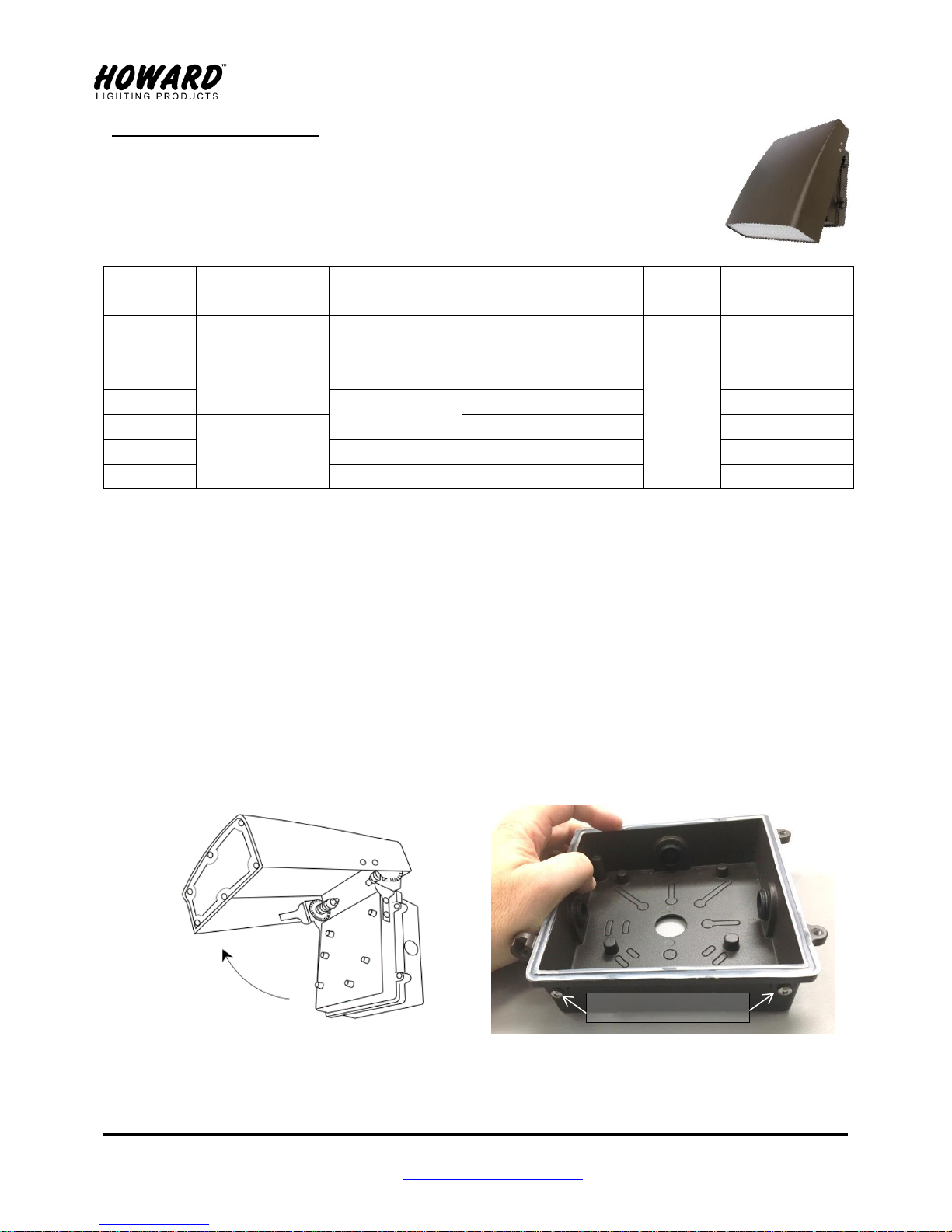
1. Open the fixture 90° to get easy access to screws holding the back plate (figure 1). Loosen 2 screws
and take off the back plate.
2. Remove weep-hole screws from the bottom of the back plate (figure 2). VL12x series has only one
weep-hole screw in the bottom center.
Page 2
INSTALLATION INSTRUCTIONS VL Series
Howard Lighting Products | 580 Eastview Drive | Laurel, MS 39443
(toll free) 800.956.3456 | (direct) 601.422.0033
www.HowardLightingProducts.com
Page 2 of 2
Rev: 11/7/2017
Fig. 3(a)
Fig. 3(b)
Fig. 3(c)
FIG. 4(a)
FIG. 4(b)
FIG. 5
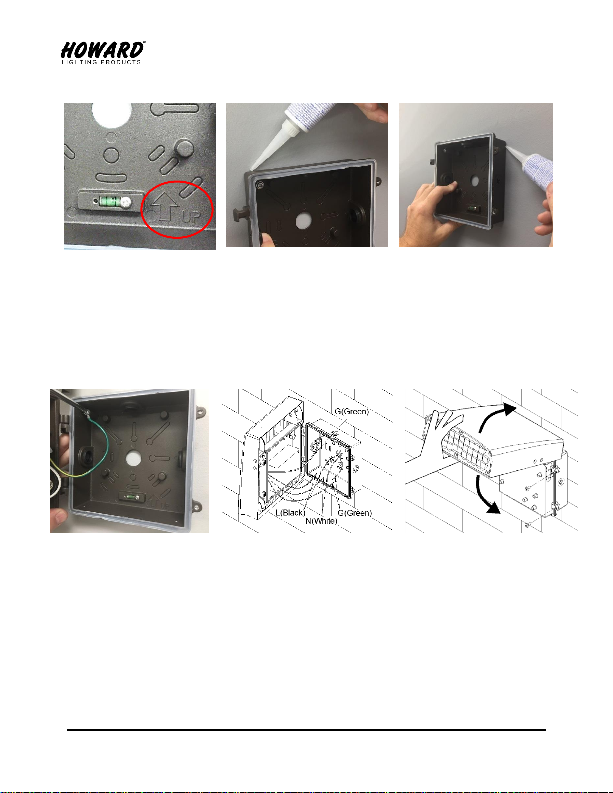
3. Tighten threaded coin plugs.
4. Orient so that the UP (↑) arrow points upwards (figure 3(a)). Secure the back plate to junction box
by screws (provided by others).
5. Apply silicone glue (provided by others) along the top and down both sides to prevent water
entering the back of the fixture. See figure 3(b) & 3(c).
6. Hang the fixture on the back plate. Connect the green ground wire with ring terminal to the back
plate (figure 4(a) & 4(b)). Using wire-nuts (provided by others) connect white to “Neutral”, black to
“Live”, and green to “Ground”.
7. Close fixture and tighten the 2 screws (figure 5).
8. Adjust fixture to desired angle.
WARNING –
Water entering the fixture is likely to cause failure. Water damage due to loose coin plugs or
failure to seal the perimeter of the fixture to the mounting surface or failure to remove weephole screws will void warranty.
 Loading...