

Page 1
Howard Industries, Inc.
Substation Transformer Division
INTRODUCTION
Howard medium power substation
transformers are designed and
built according to the most
exacting engineering standards to
provide many years of outstanding
performance and reliability in the
most demanding utility, industrial,
and commercial applications.
All designs incorporate the latest
advances in materials, design
techniques, and power transformer
technology veried with 2D and
3D analysis software. Howard’s
Substation Division has staffed
its operations with well-trained
engineers, winders, assemblers,
and testers, with many years of
experience in the development,
design, and manufacture of medium
and large power transformers.
Catalog Section
Medium Power
34-10
Substation Transformers
Howard’s Substation Transformer
Division also offers nationwide
delivery and the option of complete
job-site services, including unloading,
inspection, assembly, uid lling, and
testing. Field supervision is available
for customer-installed jobs.
PRODUCT SCOPE AND
APPLICATIONS
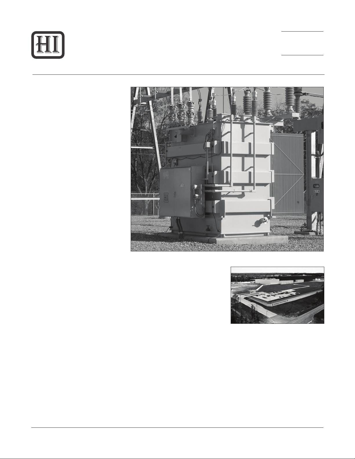
Howard Industries currently
manufactures uid-lled medium
power substation transformers with
capacities through 60 MVA (ONAN)
and primary voltage ratings through
230 kV at 900 kV BIL.
An extensive range of features and
accessories are available, including
de-energized tap changers, on-load
tap changers, forced-air cooling
systems, uid preservations systems,
and many other options to satisfy the
special requirements of virtually any
application.
Figure 1: Medium power substation transformer with forced air cooling
Howard medium power substation
transformers are suitable for a wide
range of demanding applications,
including utility substations, wind
generation sites, chemical plants, oil
and gas processing facilities, mining
operations, paper mills, steel mills,
water treatment plants, ofce and
shopping centers, internet server
facilities, and many other uses.
MANUFACTURING FACILITIES
Howard’s new 355,000 square foot
substation manufacturing facility
(Figure 2) was custom designed and
built specically for the production of
medium power transformers. Every
aspect of the facility’s design and
construction was carefully considered
to maximize its manufacturing
capabilities and provide the exibility
needed to satisfy ever-changing
Figure 2: Howard Industries Substation Plant,
Ellisville, MS
customer requirements. The facility’s
air handling systems maintain a
clean, positive-pressure environment
throughout, with temperature and
humidity controlled conditions
maintained in the insulation staging
and winding room. All oor surfaces
are sealed to help control airborne
contamination. Tank fabrication,
insulation cutting, uid storage and
Document No. 2.4.18
Revision: 2
Issued: October, 2013
Copyright © 2013 Howard Industries, Inc.
1
Howard Industries, Inc.
Laurel, MS 39440
www.howardtransformers.com
Page 2
34-10
Medium Power Substation Transformers
processing, and other potential
sources of contamination are isolated
from the main facility. Heavy-capacity,
high-lift gantry cranes can travel the
entire length of the manufacturing
area and beyond to the covered truck
and rail loading bay.
Production processes use the latest
available technologies to enhance
quality and efciency. Computer-
controlled coil sizing, vapor-phase
coil drying, computer-controlled
core lamination cutting (Georg) and
state-of-the-art electrical test systems
are just a few examples of leadingedge technologies that contribute to
process precision and repeatability.
QUALITY
Howard employees understand the
importance of quality, particularly
as it relates to the critical nature of
substation transformers. Emphasis
on quality begins at design and
follows throughout the manufacturing
and delivery processes. Only the
highest quality components and
materials are used in Howard
transformers. Attention to detail
and thorough inspection and testing
ensure that a high level of quality
is maintained. Continuous process
improvement is an integral part of our
design and manufacturing goals.
The Substation Transformer Division’s
quality management system is
designed to ensure that all of the
company’s products and services
meet or exceed its customers’
requirements and is certied as
being compliant with ISO-9001:2008
(Figure 3). The ISO-9001 standard
covers design, manufacturing,
and servicing systems, and is the
most stringent and comprehensive
standard in the internationally
recognized ISO-9000 series of
quality standards. This certication
is audited every six months with full
re-certication occurring every three
years.
Document No. 2.4.18
Revision: 2
Issued: October, 2013
Figure 3: ISO-9001 Certicate
Copyright © 2013 Howard Industries, Inc.
2
Howard Industries, Inc.
Laurel, MS 39440
www.howardtransformers.com
Page 3
Medium Power Substation Transformers
DESIGN AND MANUFACTURING PROCESSES
34-10
TRANSFORMER DESIGN
Howard’s design philosophy employs
technology in ways that provide a
cost-competitive transformer built
with conservative design margins, a
thorough verication of designs using
the latest computer analysis tools,
and automation of the design process
to reduce cycle time and eliminate
human error.
Our experienced mechanical
designers employ the latest available
computer-based design tools, such as
parametric 3D computer-aided design
systems (Figure 4) for both internal
and external layouts. The Anderson
2D nite element analysis program,
the Ansoft Maxwell 2D electrostatic
and magnostatic eld analysis
program, 3D ALGORE mechanical
analysis program, and others are
used in the determination of electrical
and mechanical design margins.
Howard substation transformers are
designed with conservative
mechanical and electrical margins to
withstand the harsh environments
encountered in today’s power delivery
systems. Exceptional short-circuit and
impulse strengths are hallmarks of
the Howard design. All transformer
designs are optimized to satisfy our
customers’ total cost of ownership
requirements.
General industry standards applicable
to Howard substation transformer
designs include IEEE C57.12.00
(Standard General Requirements for
Liquid-Immersed Distribution, Power,
and Regulating Transformers), IEEE
C57.12.90 (Standard Test Code for
Liquid-Immersed Distribution, Power
and Regulating Transformers and
Guide for Short Circuit Testing of
Distribution and Power Transformers),
IEEE C57.93 (Guide for Installation
of Liquid-Immersed Power Transformers), IEEE C57.98 (Guide for
Transformer Impulse Tests), and IEEE
C57.100 (Standard Test Procedure for
Thermal Evaluation of Oil Immersed
Distribution Transformers).
which have been precision slit to
width and stress-relieved by our
supplier. Core laminations are
precisely cut to length and mitered on
a computer-controlled Georg cutting
line (Figure 5).
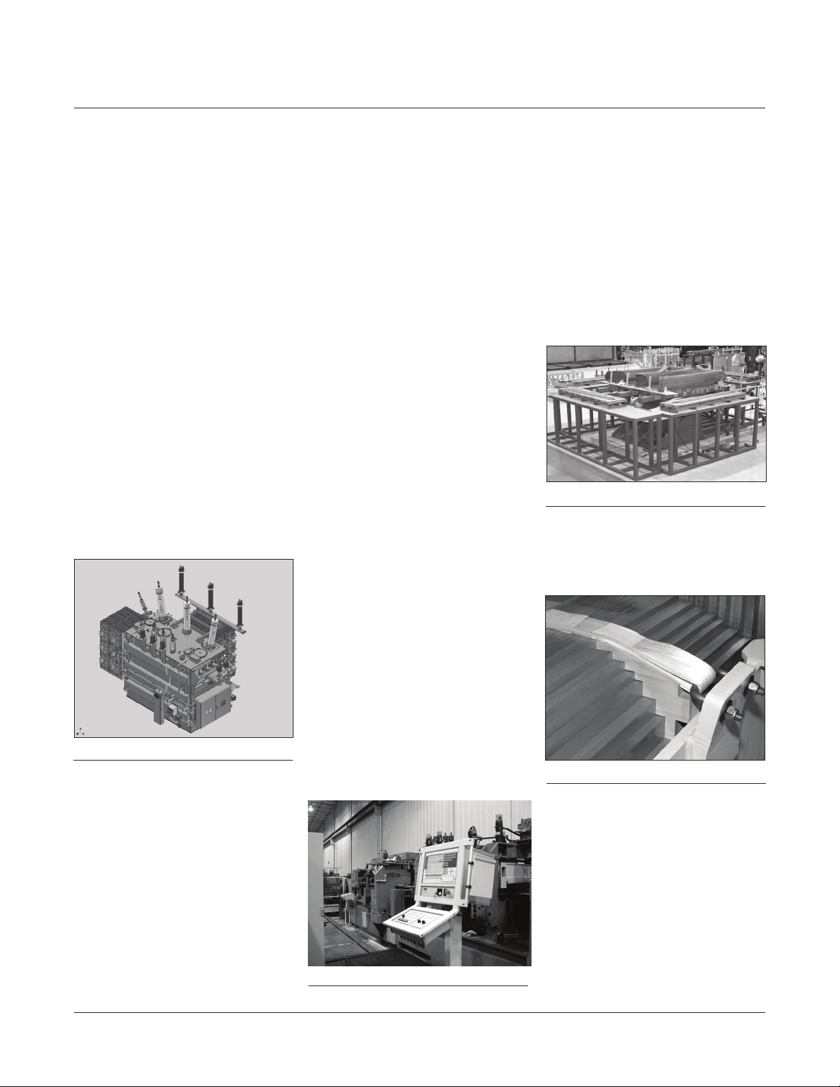
Core laminations are carefully
stacked on precision hydraulic lift
tables to prevent misalignment when
up-righting (Figure 6).
Figure 6: Core Stacking Table
Cores are securely banded and
clamped with tie plates to ensure
stability and minimize stress on the
core. Core support blocks (Figure 7)
Figure 4: Image of 3D CAD model
The design verication process
includes:
• Validation of transient voltage
response
• Validation of short-circuit strength
• Analysis of eddy losses and hotspot
calculations
• Validation of insulation design
• Verication of loading beyond
nameplate capacity
• In-rush current analysis
• Over-voltage analysis
Howard Industries, Inc.
Laurel, MS 39440
www.howardtransformers.com
MAGNETIC CIRCUIT
Howard medium power substation
transformers employ core-type
construction and are designed with
an optimized cruciform conguration
with step-lap joints to provide
excellent mechanical strength and
magnetic performance. Core designs
use regular grain-oriented steels
Figure 5: Georg core cutter
Copyright © 2013 Howard Industries, Inc.
3
Figure 7: Core support blocks
and cooling ducts are used to provide
uniform pressure across the
lamination surface. The top and
bottom core clamps are held together
by steel lock plates congured to
contain mechanical short-circuit
forces and modied as necessary
for leakage ux to limit excessive hot
spots.
Document No. 2.4.18
Revision: 2
Issued: October, 2013
Page 4
34-10
Medium Power Substation Transformers
ELECTRICAL CIRCUIT
Windings are cylindrical construction,
with concentric windings separated by
axial oil ducts (Figure 8).
Figure 8: Coil winding
The type of winding used depends
on the voltage rating. Low-voltage
windings are helical type, mediumvoltage windings are continuous disc
type, and high-voltage windings are
shielded disc. Conductor material
is C11000 grade copper, tough
pitch cast, with ASTM edge radius,
and custom tempered per design
requirements. The conductor is
insulated with thermally upgraded
crepe paper tape, wrapped in multiple
layers. Rectangular conductor or
continuously-transposed cable
(CTC) is used according to design
requirements.
Finished coils are oven dried and
accurately sized in a computer-
controlled hydraulic press (Figure 9).
Coil sizing establishes the coil’s
electrical length at a specied
pressure. Sizing pressure is
determined by design engineering,
and is sufcient to contain axial short-
circuit forces that would be generated
during throughfault conditions.
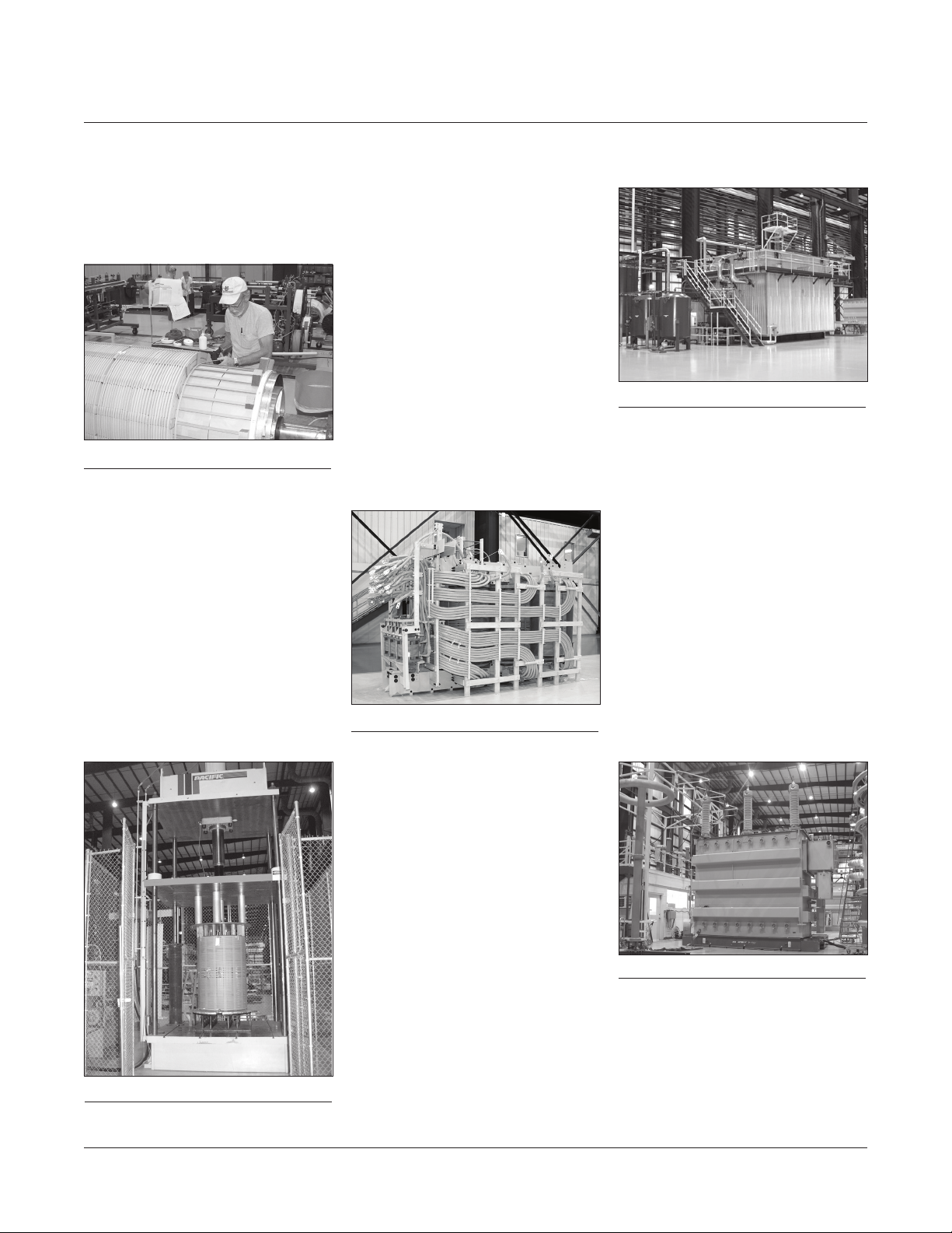
ASSEMBLY
After the coil sizing process is
completed, core and coils are
assembled together in a heavy-duty
clamping structure that produces
a rugged, stable assembly, yet
minimizes mechanical stress in the
core (Figure 10).
Figure 10: Core coil unit
High-density laminated pressure rings
transmit uniform clamping pressure
to each coil. The lead structure is
designed to provide generous
dielectric clearance and to resist
the lead forces generated by system
faults. Leads are secured using
either pressboard or kiln-dried maple
braces.
Figure 11: Mical vapor phase system
drying chamber is ooded with
transformer oil to impregnate the
insulation system fully.
FACTORY TESTING
In addition to numerous quality
inspections throughout the manu-
facturing process, nal tests are
conducted on the completed
transformer to ensure proper
function of all systems. All tests
are conducted in accordance with
applicable industry standards. Test
equipment is state-of-the-art and
capable of extremely accurate and
reliable test measurements, meeting
all the industry loss measurement
standards. (Figure 12). All test
systems are calibrated regularly
according to industry standards.
Figure 9: Coil sizing press
Document No. 2.4.18
Revision: 2
Issued: October, 2013
COIL DRYING
Core and coils are dried and oil
impregnated in a Mical automated
vapor-phase system (Figure 11).
Proper dryness is critical to maintain
the integrity and life of the insulation
system. The Mical process
automatically monitors and controls
moisture extraction in an oxygen-free
environment, producing an extremely
dry insulation system. During the nal
phase of the Mical process, the
Copyright © 2013 Howard Industries, Inc.
4
Figure 12: Electrical test station
Howard Industries, Inc.
Laurel, MS 39440
www.howardtransformers.com
Page 5

Medium Power Substation Transformers
34-10
Transformer Class
Tests
Winding resistance
Winding insulation resistance (Megger)
Core insulation resistance (Megger)
Ratio
Polarity and phase relation
Insulation power factor
Control (auxiliary) cooling losses
Single-phase excitation tests
No-load losses and excitation current
Impedance voltage and load losses
Zero-phase sequence impedance voltage
Class I (≤ 69 kV) Class II (115-765 kV)
Standard Optional Standard Optional
• •
• •
• •
• •
• •
• •
•
• •
• •
• •
• •
Temperature rise
Low frequency dielectric tests
Low frequency dielectric tests on auxiliary devices,
control, and current transformer circuits
Lightning impulse
Front of wave impulse
Switching impulse
Partial discharge
Audible sound level
Operational tests (all devices)
Dissolved gases in oil
Leak test
• •
• •
• •
• •
• •
• •
• •
• •
• •
• •
• •
Howard Industries, Inc.
Laurel, MS 39440
www.howardtransformers.com
Copyright © 2013 Howard Industries, Inc.
5
Document No. 2.4.18
Revision: 2
Issued: October, 2013
Page 6

34-10
FEATURES AND ACCESSORIES
SUMMARY OF STANDARD
FEATURES AND ACCESSORIES
Howard medium power substation
transformers are supplied with the
following standard features and
accessories:
• Capacity range: Through 60 MVA
(ONAN), with high-voltage ratings
through 230 kV (900 kV BIL)
• Service location: Outdoor
• Core: Regular grain-oriented;
mitered cruciform with step-lap
construction
• Coils: Cylindrical construction; all
copper windings, custom tempered
per design requirements; circular
windings with rectangular or
continuously-transposed conductor;
helical low-voltage windings;
continuous disc medium-voltage
windings; shielded disc high-voltage
windings
• Conductor insulation: Thermally-
upgraded crepe paper taping
• Cooling/insulating uid: Type II
mineral oil
• Fluid preservation system: Sealed
tank
• Tank: All-welded construction;
welded cover with manhole and
non-skid nish; base construction
suitable for jacking, skidding, and
rolling
• Radiators: Detachable panel type
with shut-off valves; mild steel
• Bushings: Oil-lled, cover-mounted,
condenser type with power factor
test points
• Dial-type uid level gauge
• Dial-type uid temperature gauge
with maximum temperature drag
hand
• Dial-type pressure/vacuum gauge
• Dial-type winding temperature
gauge with maximum temperature
drag hand (standard on forcedcooled transformers only)
• Automatic pressure relief device
• Rapid pressure rise relay (mounted
on isolation valve)
• Fluid ll valve
• Fluid drain valve
• Diagrammatic nameplate, engraved
stainless steel
• Tank grounding pads
• Filter press connections (top and
bottom)
• Transformer lifting lugs
• Provision for cover-mounted
posttype fall-protection device
• Paint nish: Exterior polyurethane
enamel, ANSI 70 gray color; interior
polyurethane enamel, white color
SUMMARY OF OPTIONAL
FEATURES AND ACCESSORIES
Howard medium power transformers
are available with many optional
features and accessories to satisfy
a customers’ special needs for the
operation, protection, monitoring, and
maintenance of their equipment. The
following list contains the most
frequently
requested options. Check with
the factory for the availability of other
optional features and accessories not
listed below.
• Cooling/insulating uid: Seedbased
natural ester uid
• Bushing-mounted current
transformers
• Surge arresters and mounting
brackets
• High-voltage and/or low-voltage
terminal compartments
• Wye-delta or series multiple
terminal connections
• Forced-air cooling with automatic
control system or provisions for
forced-air cooling
• Control cabinet
• Nitrogen gas uid preservation
system
• Dial-type winding temperature
gauge (standard for forced-cooled
transformers)
• Electronic temperature indicator
• Fiber-optic winding temperature
in dicator
• De-energized tap changer with padlocking provisions
Medium Power Substation Transformers
• On-load tap changer with
microprocessor-based control
• Special exterior paint color
• Galvanized or stainless-steel
radiators
• Cover-mounted fall-protection
device
INSULATING/COOLING FLUID
Power transformers are lled with
Type II mineral oil that is highly
rened
for excellent insulating properties
and inhibited for long-term
stability at elevated temperatures.
Less-ammable ester-based uids
are available as an option in the
main tank.
SELF-COOLED RATING
Power transformers rated for
selfcooled
operation (ONAN class) are
designed to operate at rated load with
natural cooling by ambient air ow
outside the transformer and natural
oil convection within the transformer
tank. Heat is radiated from the
transformer
tank and from tank-mounted
radiator panels.
FORCED-AIR COOLED RATINGS
A single-stage forced air cooling
system may be supplied to increase
the transformer load capacity (ONAF
Figure 13: Cooling fans and panel radiator
Document No. 2.4.18
Revision: 2
Issued: October, 2013
Copyright © 2013 Howard Industries, Inc.
6
Howard Industries, Inc.
Laurel, MS 39440
www.howardtransformers.com
Page 7

Medium Power Substation Transformers
class) (Figure 13).
Sealed motor-driven fans are
mounted on radiators to provide
increased air ow. Fan operation
may be manual or may be controlled
automatically by temperature sensors
mounted inside the transformer. Fans
are connected to a weatherproof
control box with weatherproof cable
and a separable connector.
A second stage of forced-air cooling
may be used (ONAF/ONAF class) to
provide a further increase in load
capacity beyond that provided by
single-stage forced-air cooling.
Stages one and two are operated
automatically by heat sensors
mounted inside the transformer tank
and a control panel mounted inside
the control cabinet.
FLUID PRESERVATION
A sealed-tank uid preservation
system is standard on all Howard
medium power transformers. The
interior of the tank is sealed from the
ambient atmosphere, such that the
gas-plus-oil volume remains constant
throughout the range of normal
operating temperatures. An automatic
pressure relief device is provided to
vent excessive pressure that might
build up gradually during extreme
overloads or fault conditions. A
pressure/vacuum gauge is provided
to measure internal pressure. Prior to
shipping the gas space is pressurized
with a dry air or nitrogen blanket.
INERT GAS SYSTEM
An optional nitrogen inert-gas system
provides a constant nitrogen
atmosphere in the gas space of the
transformer (Figure 14). The
nitrogen blanket protects the
transformer uid from deterioration
that could occur from exposure to
moisture or oxygen. Main system
components include a nitrogen
cylinder, pressure regulators, valves,
and gauges. The system also includes
provisions for various pressure
alarms. A lockable weatherproof
enclosure protects the system.
BUSHINGS
Standard bushings are oil-lled
condenser-type with porcelain
housings (Figure 15).
34-10
Figure 16: CTs mounted under cover
SURGE ARRESTERS
Surge arresters are porcelain or
polymer housed, gapless metaloxide-varister (MOV) type (Figure
17), externally mounted on heavy
steel brackets. All arresters meet the
requirements of IEEE C62.11.
Figure 14: Nitrogen system
Howard Industries, Inc.
Laurel, MS 39440
www.howardtransformers.com
Figure 15: High voltage bushing
All bushings meet the requirements
of the IEEE C57.19 series of
standards.
CURRENT TRANSFORMERS
Current transformers (CTs) are
bushing-mounted in the main tank
interior (Figure 16). All CTs meet
the requirements of the IEEE C57.13
series of standards.
Copyright © 2013 Howard Industries, Inc.
7
Figure 17: Lightning arrester
Document No. 2.4.18
Revision: 2
Issued: October, 2013
Page 8

34-10
Medium Power Substation Transformers
GAUGES
All gauges are dial-type and are
located for convenient viewing at
ground level (Figure 18).
Figure 18: Gauges
Fluid temperature and winding
temperature gauges have resettable
maximum temperature drag hands.
ELECTRONIC MONITORING
Various sophisticated electronic
monitoring systems are available as
options, including those that monitor
oil temperature, winding temperature,
pressure, moisture, gases, apparent
charge, arrester surge count, and
leakage current. Contact the factory
for these and other monitoring
systems that may be available.
CONTROL CABINET
The control cabinet provides a
weatherproof enclosure for accessory
items such as fan controls, OLTC
controls, and terminal blocks for
customer connections (Figure 19).
with three-point latch and padlock
provisions. The cabinet interior is
painted white to improve visibility and
is equipped with a work light and
accessory power outlet.
PRESSURE RELIEF DEVICE
A cover-mounted automatic pressurerelief device is provided to vent
excessive pressure that might build
up gradually during extreme over-
loads or fault conditions (Figure 20).
Figure 20: Pressure relief device
The standard device has a 6” throat
and a cracking pressure of 10 psi.
Devices with other pressure and ow
characteristics are available with
nonstandard operating characteristics. Options include alarm contacts,
indicating ag, and discharge diverter.
DE-ENERGIZED TAP CHANGER
A de-energized tap changer can be
provided to adjust the transformer
voltage ratio to meet system requirements. An external operating handle
is mounted on one end of the trans-
former near ground level (Figure 21).
The handle can be locked in any
switch position and has provisions for
a padlock.
ON-LOAD TAP CHANGER
A three-phase on-load tap changer
(OLTC) provides automatic voltage
regulation in an energized trans-
former while serving load (Figure 22).
Figure 22: On-load tap changer
OLTC’s typically operate over a range
of thirty-two 5/8% voltage steps,
sixteen above and sixteen below
rated secondary voltage. The total
tap range is typically 20% (10% above
and 10% below rated secondary
voltage). Standard OLTC’s provided
on Howard transformers use vacuum
interrupter technology manufactured
by Reinhausen or ABB.
The OLTC switch mechanism is sealed
in an oil-lled enclosure welded to
one end of the main transformer
tank. A motor drive and switch
position indicator are housed in a
weatherproof cabinet mounted below
the switch mechanism. A crank lever
is provided to operate the tap changer
manually.
Figure 19: Control cabinet
The cabinet is mounted on the side of
the transformer tank. Access to the
cabinet is protected by a hinged door
Document No. 2.4.18
Revision: 2
Issued: October, 2013
Figure 21: DETC handle
Copyright © 2013 Howard Industries, Inc.
8
OLTC control panels are housed
in the control cabinet (Figure 23).
A variety of microprocessor-based
controls are available, including those
manufactured by Beckwith, ICMI, and
Reinhausen. In addition to the
automatic regulation of secondary
voltage, control systems can also be
equipped to provide communication,
data storage, and power quality
analysis. All controls are provided with
manual override capability.
Howard Industries, Inc.
Laurel, MS 39440
www.howardtransformers.com
Page 9

Medium Power Substation Transformers
Figure 23: OLTC control
TANK
Howard transformer tanks are
rectangular all-welded steel construction and are designed for strength,
durability, and compact form. Tank
corners are folded with welds made
six inches from corners (no corner
welds). Tanks are reinforced with
external enclosed-box bracing to
provide the necessary strength and
rigidity.
Cover-mounted lifting lugs are
provided for lifting the transformer
cover. Additional lifting lugs are
provided for safely lifting the
completely assembled transformer.
Copper or stainless-steel ground
pads are located on tank sides near
ground level. Transformer covers are
constructed of a heavy steel plate
that is internally braced and welded
to the tank. Bolted and gasketed
manhole covers are provided to
allow convenient access to the main
tank interior. Covers are supplied
with provision for a post-type fall
protection device. Other fall-protection
provisions or systems are available as
options.
34-10
with a durable polyurethane topcoat.
Tank interiors are painted white. Tank
covers have a slip-resistant surface
nish.
RADIATORS
Panel-type radiators provide
additional cooling to supplement heat
radiation from the transformer tank
(Figure 13). The number and size of
radiators is determined by the design.
Radiators are typically detachable
and are provided with individual
shutoff valves. Standard radiators are
made of cold-rolled mild steel that is
primed and nished with a durable
polyurethane top coat. Stainless steel
and galvanized radiators are available
as options.
OTHER FEATURES AND
ACCESSORIES
Contact the factory for other features
and accessories that are not discussed here but may beavailable as
options.
The standard tank base is construct-
ed of a heavy plate steel that is
suitable for rolling or skidding in all
directions. Jacking pads are provided
on all four corners of the tank to allow
for jacking of the completely
assembled transformer.
Tank surfaces are sand blasted and
coated with a rust inhibiting primer.
After assembly and before shipping,
completed transformers are leak
tested, washed and then nished
Howard Industries, Inc.
Laurel, MS 39440
www.howardtransformers.com
Copyright © 2013 Howard Industries, Inc.
9
Document No. 2.4.18
Revision: 2
Issued: October, 2013
Page 10

34-10
Medium Power Substation Transformers
DELIVERY AND INSTALLATION
Delivery is made by truck whenever
possible or by rail when transformer
size or weight makes truck delivery
impractical. An impact recording
device is provided on all rail ship-
ments and can be provided on truck
shipments upon customer request.
Figure 24: On-site installation
Impact recorders measure and store
three-axis impact data, identifying any
abnormally severe impacts that might
have caused damage to the transformer during transportation.
Howard Industries offers a full
complement of eld installation
services, including unloading, inspec-
tion, assembly, vacuum oil lling, and
testing under the supervision of eld
service technicians (Figure 24). Field
supervision is available for customerinstalled jobs. Field inspection
includes checks of bushings, gasket
seals, tank pressure, tap changer
operation, and controls. Tests include
turns ratio, insulation resistance,
power factor, internal moisture, and
oil dielectric strength.
Document No. 2.4.18
Revision: 2
Issued: October, 2013
Copyright © 2013 Howard Industries, Inc.
10
Howard Industries, Inc.
Laurel, MS 39440
www.howardtransformers.com
Page 11

Medium Power Substation Transformers
34-10
NOTES
Howard Industries, Inc.
Laurel, MS 39440
www.howardtransformers.com
Copyright © 2013 Howard Industries, Inc.
11
Document No. 2.4.18
Revision: 2
Issued: October, 2013
Page 12

34-10
Medium Power Substation Transformers
Document No. 2.4.18
Revision: 2
Issued: October, 2013
Medium Power Substation Transformers
Catalog Section 34-10
Document 2.4.18, Revision 2, October 2013
Copyright © 2013 Howard Industries, Inc.
Laurel, Mississippi
Telephone: 601-425-3151
Fax: 601-649-8090
E-mail: mkt@howard.com
Web: howardtransformers.com
Copyright © 2013 Howard Industries, Inc.
12
www.howardtransformers.com
Howard Industries, Inc.
Laurel, MS 39440
 Loading...