

Page 1
ST 400
ST 400
HOWARD
Operating Instructions
Page 2

ST 400
CONTENTS
Safety precautions........................................ 14-18
Specification & description ........................... 19-20
New maschine ....................................................21
Attaching machine to the tractor.........................21
Depth control ......................................................21
Rotors.................................................................22
Lubrication + maintenance .................................22
Operating instructions ........................................23
Operational advice .............................................24
Introduction
Howard would like to thank you for purchasing this machine and offer their support and assistance
throughout its productive life.
This machine has been designed and manufactured as a tractor driven, ground cultivator - no other use
is intended.
Please read and understand this manual before operating the machine.
Warranty
The warranty applicable to your machine is detailed on separate documentation which should accompany
this manual. If this is missing, please contact your dealer.
Serial Number
The Serial Number and Model are stamped on the Identification Plate attached to your machine.
For future reference record this information below. Always quote them when ordering spare parts.
MODEL ________________
SERIAL No. ________________________
Date Purchased: ________________
14
Page 3
ST 400
SAFETY PRECAUTIONS
PLEASE READ. IT MAY SAVE A LIFE.
!
SAFETY IS YOUR RESPONSIBILITY.
The safety of operators and any other connected personnel
is a major component of; machine design, manufacture,
retailing, commissioning, operation and maintenance.
Howard have designed and manufactured this
machine with as many safety features as possible. The
retailer’s responsibility is to ensure you have selected the
correct machine for your tractor/application and to
commission this machine.
Your responsibilities as owner or operator are to ensure
the safety of any personnel in connection with; the operation,
transport, maintenance or storage of this machine. Be
aware of your responsibilities and carry them out. The owner
or an appropriately designated officer, if the owner is a
company or corporation, is responsible for all safety issues
related to this machine.
The most important safety device attached to this machine
is a Safety Conscious Operator whose training and
experience must include:
• Correct and complete installation and commissioning of
the machine to ensure safe and reliable operation in the
intended application.
• Training in safety issues, operation and maintenance of
this machine in its application prior to beginning work.
This training is to be reviewed or repeated annually.
• Being aware of their environment to the extent that
unforeseen safety issues that may arise are dealt with to
ensure the safety of all personnel (including operators,
maintenance personnel and bystanders).
This is the SAFETY ALERT symbol and means:
ATTENTION ! SAFETY ISSUE !
!
Failure to comply with the given instruction could result in
severe injury or death.
If you have questions not answered in this manual please
contact your dealer or distributor.
IF YOU REQUIRE MORE COPIES OF THIS MANUAL PLEASE CONTACT YOUR DEALER.
ALTERNATIVELY YOU ARE WELCOME T O COPY
AND DISTRIBUTE THIS MANUAL TO THE
OPERAT ORS AND MAINTENANCE PERSONNEL.
SAFETY DECAL CARE
• Keep safety decals clean and legible at all times. Replace
any missing safety decals or any that have become
illegible. Safety decals can be purchased from you dealer
or distributor.
• If any part is replaced that supports a safety decal ensure
that a decal is affixed to the replacement part.
ATTACHING SAFETY DECALS
1.Clean and dry the area where the decal is to be affixed.
Warm soapy water is the best as some cleaning agents
leave an oily film which may prevent the decal adhering.
2.Remove/fold back a small portion of the backing and affix
the exposed portion of the decal in the desired position.
3. Peel back the remaining backing paper from under the
decal and smooth down the decal with a rag, working
any bubbles towards the edge of the decal.
4. Any bubbles that remain trapped can be pierced with a
pin and smoothed down.
ENGLISH
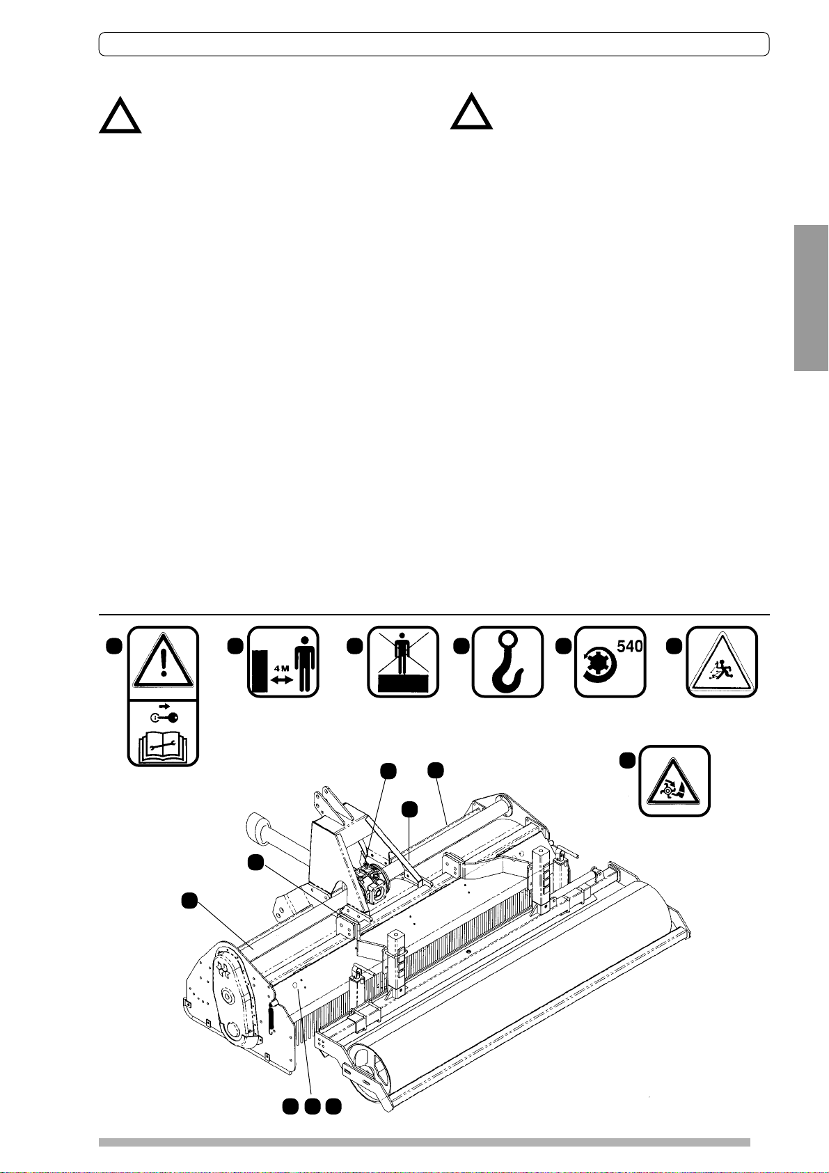
1 65432
WARNING!: READ
CAREFULLY THE
INSTRUCTIONS.
BEFORE HANDLING OR
REPAIRING THE MACHINE
REMOVE THE TRACTOR
IGNITION KEY
7
STA Y AT LEAST A T A
DISTANCE OF 4 METERS
WHEN THE ROTAVATOR IS
RUNNING.
4
DO NOT STAY ON THE
ROTAVATOR WHEN
TRANSPORTING
NEITHER WORKING
5
1
4
LIFTING
POINT
THE DRIVE IS BY A
PTO FROM A 540
TPM TRACTOR PTO
DANGER!
OBJECTS
PROJECTION.
7
MAINTAIN HANDS AND FEET AWAY WHEN
ROTAVATOR IS WORKING
Fig. 1
6
32
15
Page 4

ST 400
A T ALL TIMES
• Use the machine only for the purpose for which it has
been designed, and in accordance with the instructions
in this operators manual.
• Ensure that only responsible, properly instructed people
operate this machinery. Inexperienced operators will
require training, followed initially by careful supervision.
• Children are not permitted to operate this machinery.
• Keep children well clear and appropriately supervised
when connecting/disconnecting the tractor, operating or
maintaining this machinery.
• Do not wear clothes that are loose fitting or with drawstring
ties which can catch in moving parts.
• Wear appropriate protective clothing and equipment.
Boots are a minimum, however if your tractor is not fitted
with a controlled environment cab you may also need
protection from prolonged exposure either to noise, dust
or sunlight.
• Interpret ‘Left’ and ‘Right’ as if seated in the operators
seat and facing forward.
BEFORE OPERATION
• Read and understand this manual.
• The tractor to be connected to the machine:
- Must be the tractor that the machine has been
commissioned to operate with. Check that it has been
correctly maintained and has not been re-configured
(for example front weights removed etc) which may
reduce stability and control.
- Consult the Tractor Manufacturers Manual for
instructions on mounting implements and safe working
methods.
- Is recommended to be fitted with a Roll Over Protection
System (ROPS).
- Must be one the operator is familiar with.
• Prior to starting the tractor ensure the PTO is disengaged
and the tractor is in neutral.
• Do not allow anyone to stand between the tractor and
machine while backing the tractor up to attach it.
- Quick hitch systems are recommended for both Safety
and convenience.
- Before attempting to connect the universal drive shaft
to the tractor, lower the machine to the ground, stop
the tractor, apply the park brake and remove the key.
• Visually inspect the machine and check:
- Hitch pins and drive shaft are secure.
- No components are excessively worn, cracked or
otherwise defective and all bolts are tight.
- Guards, covers, warning labels and safety devices are
all correctly fitted and operative.
- Maintenance as per schedule has been carried out.
- No tools or other unsecured items have been left on
the Rotavator.
• Practice operation of the tractor and machine
combination.
- T ake sufficient time to become completely familiar with
all controls, particularly those required to bring both
tractor and machine to an emergency stop if so
required.
- Progress slowly initially and check stability, steering and
braking are satisfactory.
• Ensure the work area is clear, especially of children or
animals.
• Inspect the work area for hidden obstructions which may
constitute a hazard.
DURING OPERATION
• Ensure the work area is clear, especially of children or
animals.
• Do not attempt to start the tractor or engage the PTO
until correctly seated in the driver’s seat.
• Never leave the tractor running unattended.
• Do not allow passengers on the machine. [Or on the tractor unless approved seating is available.]
• Never attempt to make adjustments or perform
maintenance functions while the machine is operating.
• Observe all safe driving procedures:
- Reduce speed when working on sloping ground or
during sharp turns.
- Do not attempt to work on steeply sloping ground where
there is a risk of the tractor overturning.
- Do not attempt to work near the edge of drop-offs or
banks.
- Avoid sudden starts and stops.
• After striking an obstacle, stop the tractor and implement
and inspect it for damage. Repair as necessary before
continuing.
• Disengage the PTO when transporting the implement or
when not in use.
• When halting operation, even temporarily, lower the
machine to the ground, stop the tractor, apply the park
brake and remove the key.
• Allow the machine sufficient time to cool down before
performing any maintenance, or changing gears in the
Selectaspeed gearbox. [Oil and other transmission
components may be hot enough to inflict burns.]
• Note:
- By virtue of its mode of operation it is not possible to
totally enclose a machine with guards.
- Contact with the blades while operating can result in
severe injury or death.
- Do not allow anybody (operators, maintenance
personnel, bystanders or especially children) anywhere
near the blades whilst the implement is operating. Note
that children will often be attracted to placing objects
into the blades if you leave it running - this machine is
not a toy.
- Be aware that machine blades will not only cut, but
drag limbs etc. into further danger.
- Ensure that all shielding is in place before operating. If
guards are removed for maintenance work, ensure they
are replaced correctly upon completion. Repair or
replace any damaged guards.
- NEVER place hands or feet under the machine, nor
endeavour to make any repairs or adjustments while
the blades are rotating; they are capable of inflicting
serious injury.
- NEVER touch the blades or attempt to free any jammed
obstacle while the tractor engine is running. The clutch
may be slipping and removal of any obstruction may
allow the blades to rotate, the result possibly being
serious injury.
16
Page 5

ST 400
FOLLOWING OPERATION
• Visually inspect the machine and check:
- All bolts are tight.
- That no components are excessively worn, cracked,
damaged or otherwise defective.
• Note and organise any maintenance required.
• Allow the machine sufficient time to cool down before
performing any maintenance. The gearboxes, lubricant
and other transmission components may be hot enough
to inflict burns.
• Refer to TRANSPORT SAFETY and STORAGE SAFETY
for issues related to travel to/from operation and
disconnection of the machine from the tractor.
STORAGE SAFETY
• When unhitching the machine and before leaving the tractor to disconnect the universal drive shaft and remove
hitch pins:
- Check that the PTO drive has been disengaged.
- Stop the tractor, apply the park brake and remove the
key.
• Store the machine away from human activity and in particular do not permit children to play around, or on, stored
equipment.
• Store the machine in a dry level area and ensure
parkstands and wheels/roller are securely positioned to
prevent it tipping, falling over or rolling onto any personnel
(particularly children).
MAINTENANCE SAFETY
• Maintain the machine as detailed in the given schedule
and check for any damage after use. Poor maintenance
is an invitation to trouble.
• Ensure that all shielding is correctly in place when
maintenance is completed. Repair or replace any
damaged guards. Warning or instruction decals are to
be kept in a readable condition; unreadable decals must
be replaced.
• NEVER place hands or feet under the machine nor
endeavour to make any repairs or adjustments, while the
blades are rotating; they are capable of inflicting serious
injury.
• If working on the implement whilst it is raised on the
tractor’s three-point linkage, ensure:
- That the tractor is turned off and the ignition key is re-
moved to prevent accidental starting.
- The park brake is engaged and the wheels chocked to
prevent the tractor moving.
- The PTO drive is disengaged.
- The machine is properly supported by blocks or stands.
DO NOT rely on the tractor’s hydraulic system to
support the implement.
• Modifications or fitment of non genuine replacement parts.
- If the equipment is modified in any way from the origi-
nal design, the manufacturer will not accept any liability
for any injury or warranty as a result of their use or
attempted fitment.
• Fasteners.
- Fit only the correct replacement fasteners and tighten
fasteners to the torque specified in the manual.
Incorrect (too weak) fasteners may break when torqued
to the required setting or, if too strong, may induce
failures in other components.
• Follow safe workshop practices during any maintenance:
- Keep working area clean, dry and in particular free of
oil spills.
- Ensure the workshop is adequately ventilated. Do not
run the tractor engine inside a closed building. The
exhaust fumes can reduce mental alertness initially and
will progressively cause death by asphyxiation.
- Use tools, lifting or jacking equipment suitably capable
of the intended task.
- Ensure electrical equipment is safe to use before
operating.
- A fire extinguisher and first aid kit should be readily
accessible during maintenance.
- Tools, parts and other service equipment must be removed to appropriate storage locations prior to any test
running.
- Do not wear baggy, ill-fitting or frayed clothing when
working around transmission components.
- Wear suitable gloves when handling or working with
sharpened cutting elements.
- Ensure bystanders, especially small children, are kept
clear during maintenance or while making any
adjustments.
• Hydraulic fluid can be dangerous.
- When disconnecting any hydraulic fluid line, shut off
the hydraulic supply and relieve the hydraulic pressure.
- Never use hands to locate hydraulic fluid leaks.
Escaping hydraulic fluid is capable of cutting and
penetrating skin. Use a small piece of cardboard or
wood.
- Minor cuts are susceptible to infection from hydraulic
fluid. Gangrene can result. If injured by escaping
hydraulic fluid or you suspect you have been infected,
seek medical treatment immediately.
TRANSPORT SAFETY
• When transporting the implement on a tractor on public
roads ensure that you comply with the relevant
regulations.
- Class of roads permitted for travel may be restricted.
- Transport may restricted to daylight or, off peak traffic
hours.
- Signs indicating width may be required.
- Lights indicating vehicle width if transported within the
hours of darkness may be required.
If in doubt, contact your government department responsible
for road transport.
• Secure the machine for transport.
- Disengage the PTO when transporting.
- Ensure all hitch pins are correctly fitted with retaining
pins.
- Mechanically secure hydraulic cylinders to prevent
cylinders creeping.
• Observe the tractor manufacturers regulations and
recommendations - specifically those relating to:
- Maximum transport loads.
- Maximum speed.
• Passengers
ENGLISH
17
Page 6

ST 400
- Do not allow passengers to ride on the tractor unless a
specific seat is provided.
- Do not allow anyone to ride on the implement when it
is being transported.
• Consider other road users.
- Plan your route to avoid heavy traffic and peak traffic
periods.
- Be a safe and courteous driver. Give way to oncoming
traffic in all situations, including narrow bridges,
intersections etc.
• Adopt safe driving practices:
- Lock tractor brake pedals together. Never use
independent breaking at transport speeds.
- Drive at a safe speed to ensure control and ability to
stop in an emergency. Ensure the additional weight of
the machine on the linkage does not compromise
steering and braking - for example front weights or
repairs to the brakes may be required if the tractor is
not safe to drive.
- Reduce speed during turns. Tractors have not been
designed for fast cornering.
- Use engine braking when going down hills - do not
coast.
- Do not drink alcohol and drive.
• Watch for obstructions, particularly if over-width.
• Observe any load ratings applicable on bridges.
IDENTIFICATION OF HAZARDS
• Owners and operators must be prepared to assess their;
equipment, operators, maintenance procedures and
applications to identify safety hazards.
• Appropriate methods to reduce the hazards identified
must then be applied.
MACHINE SUITABILITY TO APPLICATION
Machine have been designed and manufactured as a tractor driven, ground cultivator - no other use is intended.
• Before beginning work it is necessary to assess the effect
of the machine on the safety of both the operator and
any potential bystanders. It is reccomended that you
contact the manufacturer or distributor for assistance in
this area.
AUTHORISED OPERATORS & TRAINING
If you are an employer, do not assume an operator is trained
for use of this equipment, (you would not let an unlicensed
driver borrow your car !).
• Ask to see licences if applicable, and record numbers
and validity dates.
• Request details of previous experience, in writing and
check them out if appropriate and ensure such records
are retained.
• Devise a suitable training course for operators if
appropriate, and ensure records of their completion are
retained.
MAINTENANCE RECORDS
Recommended maintenance is detailed in the Lubrication
& Maintenance section. Failure to follow these may
jeopardise safety as well as economic operation.
Records of periodic maintenance are important as they
detail when and who carried out the last maintenance and
inspection. Appropriate checklists should include
maintenance as detailed and in particular the following
safety aspects:
- SAFETY DECALS AFFIXED & LEGIBLE.
- GUARDING - All fitted and secure.
- CRITICAL FASTENERS SECURE
Fit all safety guards before operating. Operation is not permitted without safety guards
!
fitted. These are not fitted at the factory due to freight limitations.
18
Page 7

ST 400
NEVER
- Touch any moving parts of the machine or parts
which may be hot from opertaion.
Check oil levels whilst the machine is running.
- Carry out adjustments or repairs to a mounted
machine unless the tractor engine is stopped and the
machine firmly supported or lowered to the ground.
- Leave the tractor seat unless the machine is lowered,
the pto drive disengaged, the gear shift in neutral,
the brake applied, the engine stopped and the ignition
key removed
BE A SAFE OPERATOR BY THINKING –
BEFORE ACTING
PTO DRIVE SHAFT GUARDS
HOWARD PRODUCTS are supplied with non-rotating PTO
Drive Shaft which must be correctly fifted and well
maintained.
Before and after each use PTO driven implements should
be examined to ensure the Drive Shaft rotates freely in the
guards, the guards are undamaged, securely fifted, correctly
seated on the shaft grooves and the restraining chains
attached to the tractor and implement.
Should the guards be broken, damaged or badly fitted the
implement must no be used damaged parts habe been
replaced and/or bad fitting corrected.
Always ensure the guard tubes do not separate at tthe PTO
Drive Shaft’s longest working or transport lengh, or at it’s
shortest.
Avoid damage to guards when the PTO Drive Shaft is being
connected or disconnected from the tractor by resting it on
a suport.
Never allow PTO Drive Shaft Guards to fall into the
implement or drop to the ground: damage will almost
certainly occur.
Always ensure the sliding surfaces of the guard tubes are
clean and the guard bearings lubricated.
When replacing worn or damaged sections of the Guard,
use special tools available from the makers.
Always follow the fitting, lubrication and maintenance
instructions supplied by the makers of the PTO Drive Shaft
Guard.
UNLESS CORRECTLY GUARDED
PTO DRIVE SHAFTS CAN KILL
!
ENGLISH
Minimum overlap in straight position
19
Page 8

ST 400
Model
ST400S-130M 130 152 480 30 40-75
ST400S-155M 155 177 560 36 40-75
ST400S-165M 165 187 251 600 39 45-75
ST400S-180M 180 202 640 42 45-75
ST400S-205M 205 227 720 48 50-75
Fig. 1
A
Working Transport Rotor speed Weight Number of Tractor engine
width cm width cm rpm kg blades HP
E
F
A
B
C
F
E
L
D
I
G
G
H
K
B
C
D
DESCRIPTION
Fig. 1 indicates assemblies refered to in the
text of this manual which are named bellow:
A: PTO drive shaft
B: Gerabox
C: Side drive
D: Rotor
E: Frame
F: Top mast
ST-400 is a Stone burier designed to prepare perfect seed
beds, both for flat field crops (grass, turf, vegetables ) or for
vegetable planting in beds (tomato, strawberries, vegetables
in general.)
The reverse rotating rotor, lifts the soil in the front of the
machine and the rear sieve is separating stones and clods
from the fine soil. The result is a structured seed bed with
two separate layers that are ensuring:
• Perfect operation of the seed drill or planter
• Better crop implantation: The first growing phase is crucial
• Trouble free operation of the following operations: mower,
harvester.
G: Rubber hull
H: Sieve
I: Depth control
J: Bed former
K: Roller
L: Levelling board
I
H
J
• For turf plantations: even surface for sport practice (golf,
football etc)
The new ST-400 receive the benefit of a flexible rubber top
with variable geometry (pat. Pending). This feature helps
the machine to avoid the most common disadvantages that
usually appear on this kind of machines:
1.Work in wet soils: The rubber top is avoiding soil sticking
and longer free operation than metal shield machines
2. Noise level: The machine works in a substantial lower
noise level than a conventional machine even in fields
with high stone content
3.Frame deformation: No permanent deformations of the
top are expected due to stone impacts. The rubber
absorbs the energy of the impacts from the stones and
this is not transmitted to the frame.
After long service, just changing the rubber hull as a
wearing part, and the machine is maintained as if it was
new.
4.Loads on transmission: The machine is protected by a
friction clutch, but even though, if a severe blockage
happens with a stone, the rubber top is reducing the loads
on the transmission elements, protecting them.
WARNING! THE MACHINE CAN ONLY WORK IN SOILS
WITH STONES NOT BIGGER THAN 12 CM.
OTHERWISE THE MACHINE CAN HAVE A SEVERE
OBSTRUCTION.
20
Page 9

ST 400
Fig. 2 Fig. 3
NEW MACHINE
PTO shaft
For transport purposes, the PTO shaft is dismantled and
must be refitted.
Lubrication and general
With the machine standing level ensure the following
preparatory
work has been done:
1.The gearcase filled to the level plug (A) (fig. 2) Capacity:
2l. Use SAE 90 oil.
2.The gearbox filled up to the level mark in the inside rod
(A) (fig. 3). Capacity 1,5 l.
3.All oil and grease points as indicated on p. 22 (Lubrication)
4.All nuts and bolts tightened. (Re-tighten after first hour’s
work)
SERIOUS DAMAGE CAN RESULT
FROM FAILURE TO CARR Y OUT THE
!
ABOVE PROCEDURES
PTO, lift the machine on the hydraulic lift linkage until the
PTO dirve shaft attains an angle of 40 º and set the limit
stop on the hydraulic lift control quadrant. (fig. 5)
A TTENTION! : THE PTO DRIVE SHAFT
!
ANGLE MUST NEVER EXCEED 40º.
Finally check that during transport and use the PTO drive
shaft does not “bottom“ or separte and that the maximum
angle of 40 º is not exceeded. Should it not be possible to
obtain the aforementioned setting with your tractor, SEEK
ADVICE, it may be necessary to reduce the length of the
PTO drive shaft by cutting.
B
E
A
Fig. 6
A
C
ENGLISH
Fig. 5
Fig. 6
ATTACHING THE MACHINE TO THE
TRACTOR
The PTO drive shaft must be set to a safe working length to
ensure the male shaft does not “bottom“ or separate from
the female tube under all conditions of use and transport.
To determine the correct mounting position: with the
machine on a firm level surface the Depth Control equipment
should be adjusted until the gearbox input shaft is horizontal (fig.5). Position the tractor at a distance from the machine
to give 150 mm (6“) minimum engagement of the male half
of the PTO drive shaft in the female tube when connected
to the tractor. This establishes the safe working length of
PTO drive shaft for connection to the tractor.
Position the tractor lower link ball joints in line with the
mounting pins. Connect the tractor lower links. Fit the tractor upper link and secure. Attach the PTO dirve shaft to the
pressure plate by the studs and tighten the nuts. Attach the
PTO drive shaft guard chains to the tractor and machine.
Attach stabilizer bar or check chains to limit sway to 50 mm
(2”). Adjust tractor linkage to level machine laterally and
longitudinally (fig. 5 and 6). Before engaging the tractor
D
Fig. 7
Depth control
Machines with roller (fig 6):
Adjust the roller height by means of the spindle (A) until the
required position.
It is also necessary to adjust the height of the levelling board
by means of the spindles (B) in order to get a correct and
regular soil flow.
In order to obtain a good result the machine should be
adjusted in horizontal position. By adjusting the length on
the 3rd point linkage, ensure that the lower profile in the
side plates is horizontal.
It is possible to offset the position of the roller, ensuring a
good overlap between the passes, without marking in the
field. Optionally the offset is made by means of a hydraulic
ram.
Machines with bed former (Fig.7):
On these machines the adjustment is made by adjusting
the height and the working angle of the bed former.
Modify the height by means of the spindle (A). In order to
make the correct adjustment it might be necessary to modify
the working angle. By moving the adjusting plate (C) the
working angle is changed and is possible to modify the
pressure on the soil. The plate (D) is then regulated in order
to close the bed former sides.
Is also possible to change the height of the side skimmers
(E) to regulate the incoming soil flow.
21
Page 10

ST 400
X
ROTOR AND BLADES
ST400 are fitted with original HOWARD BLADES model
9900/9901. See fig. 8 where the left blade is marked with
X. Use always only ORIGINAL HOWARD BLADES and
HOWARD.blade bolts. As an option it can be fitted
wiht»speed» blades model 9953/54 ( Fig.9 )
Fig. 10
Fig. 8
The blades must form a «scroll» patern (fig. 10). This ensure
that they enter the soil at regular intervals to even out the
load on the transmission.
When replacing worn blades, remove one blade and fit the
new one in its place before proceeding to the next. This will
ensure that the blade «scroll» patern is mantained.
D = right
I = left
Fig. 11
Rotacadet
ST400 can optionally be is fitted with a special rotor with
four blades per flange type ROTACADET (9941/9942)
When replacing worn blades take special attention to the
following instructions in order to get the correct mounting
and maintain the «scroll patern·». (Fig. 11)
LUBRICATION + MAINTENANCE
D
A
S
A
S
ATTENTION! IN ORDER TO OBTAIN A CORRECT MAINTENANCE AND FUNCTION OF
!
YOUR MACHINE IS IMPERATIVE TO FOLLOW THE ENCLOSED INSTRUCTIONS:
A
S
S
D
D
D
• (D) DAILY:
1.Lubricate with grease gun PTO spiders.
2.Lubricate with grease gun right hand stub axle bearing
3. Lubricate with grease gun roller bearings
•
(S) WEEKLY:
1.Top up with oil SAE W85-140 The gearbox.
2.Top up with oil SAE W85-140 The side drive gearcase.
3.Tighten fasteners.
22
• (A) EVERY 500 WORKING HOURS:
1.Drain flush and fill with oil SAE W85-140 the gearbox.
2. Drain flush and fill with oil SAE W85-140 the side drive
gearcase.
3. Lubricate with oil the spindles
Page 11

ST 400
Operational advice
Insufficient Depth Obtained
(a) adjust depth control equipement
(b) insufficient power : use lower tractor gear
(c) chaincase on hard soil. Further passes required
(d) blades “trowelling” (rolling over ground), use lower tractor gear
(e) blades incorrectly mounted
Tilth too fine
(a) use a faster tractor gear
(b) raise levelling board
ENGLISH
Tilth too coarse
(a) use lower tractor gear
(b) wait until soil is drier if sticks
(c) lower the levelling board
Blades “Ballinq up” with soil
(a) ground too sticky for working
(b) raise levelling board
(c) decrease tractor speed
Excessive Blade Wear
(a) reduce rotor speed
(b) replace loose or bent blades
Machine “Bumping” on Ground
(a) obstacles entangled in blades
(b) blades incorrectly mounted with no scroll effect or blades fitted with blunt edge leading or broken
blades
Obvious Points
(a) Machine not level - cutting too deep on right side. Shorten right hand tractor lift rod or adjust
depth control wheel (b) Not overlapping - drive closer to last run
(c) Working on hillsides. Work up the slope if possible. If lateral work cannot be avoided, work from
the top to the bottom in order to limit any terracing effect.
Advice
1. When operating the machine the most suitable practice is to work in “lands”
2. The worked ground should always be to the right of the driver.
3. Working on the field headlands should not be carried out until the “lands” have been completed.
4. Always raise the machine before turning.
THE MACHINE SHOULD NEVER BE
!
LOWERED WHILST THE TRACTOR IS TURNING.
23
 Loading...