

Page 1
Howard Industries, Inc.
ISO-9001 Certi ed
Catolog Section
94-10
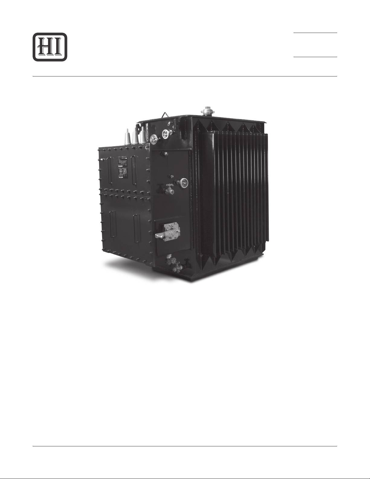
Network Transformers
Introduction
Howard network transformers are designed and built
according to the most exacting engineering standards to
provide many years of outstanding performance and reliability in the most demanding utility network applications.
Product scope includes capacities from 300 kVA through
2,500 kVA with high-voltage ratings from 2.4 kV through
34.5 kV and low-voltage ratings through 600 Volts.
Network transformers are typically used to supply
power to grid-type secondary distribution systems in
areas of high load density, such as are found in large
cities and are designed for either vault-type or subway-
Catalog Section 94-10
Network Transformers
Issued: April 9, 2010
Copyright © 2010 Howard Industries, Inc.
Figure 1: Network Transformer
type applications. Vault-type network transformers are
designed for installation in above-ground dry vaults, where
occasional submersion may occur. Subway-type network
transformers are designed for installation in subsurface
vaults, where frequent or continuous submerged
operation is likely. Subway designs may also be used in
vault-type applications.
Howard Industries, Inc.
1
www.howardtransformers.com
Laurel, MS 39440
Page 2

Design and Manufacturing
Network Transformer94-10
Transformer Design
Howard network transformers are designed with conservative mechanical and electrical margins to withstand
the harsh environments encountered in today’s network
distribution systems. Core-and-coil designs are optimized
for the lowest procurement cost or lowest total owning
cost according to each customer’s specic requirements.
All designs are guaranteed to meet the U.S. Department of
Energy’s minimum efciency standards. General industry
standards applicable to Howard network transformer designs include IEEE C57.12.00 Standard General Requirements for Liquid-Immersed Distribution, Power, and Regulating Transformers, ANSI C57.12.40 American National
Standard for Secondary Network Transformers, Subway
and Vault Types (Liquid Immersed)—Requirements, IEEE
C57.12.90 Standard Test Code for Liquid-Immersed Distribution, Power and Regulating Transformers and Guide for
Short Circuit Testing of Distribution and Power Transformers, IEEE C57.93 Guide for Installation of Liquid-Immersed
Power Transformers, IEEE C57.98 Guide for Transformer
Impulse Tests, IEEE C57.100 Standard Test Procedure for
Thermal Evaluation of Oil Immersed Distribution Transformers, 10 CFR Part 431, Department of Energy, Energy
Conservation Program for Commercial Equipment: Distribution Transformers Energy Conservation Standards; Final
Rule, and 10 CFR Part 431, Department of Energy, Energy
Conservation Program: Test Procedures for Distribution
Transformers; Final Rule.
Core-and-Coil Design
Howard’s ve-legged core-form design provides excellent
mechanical strength that has been proven through rigorous design verication testing and years of eld service.
Mechanical strength is achieved through the use of a rugged steel mounting frame that provides solid support for
core/coil assembly.
Core-and-coil designs are optimized to provide the lowest
total owning cost or lowest purchase price according to
each customer’s specications. In addition, all network
transformer ratings, where applicable, are designed to
satisfy the minimum efciency standards set by the U.S.
Department of Energy.
Core Construction
Cores are fabricated using high-efciency grain-oriented
silicon steel that has been precision slit and edge conditioned by the supplier. Step-lap joints are used to
minimize losses and exciting current, and to insure quiet
operation. Cores are designed to operate at ux densities
well below saturation. Stress-relief annealing is employed
to maximize efciency and establish the required rectangular shape of each core loop. Prior to assembly each
core is carefully tested to ensure it meets dimensional, exciting current and no-load loss specications. Amorphous
metal cores are available for those applications requiring
ultra-low excitation losses.
Coil Construction
High-voltage coil windings are constructed of copper
or aluminum magnet wire. Automatic wire tensioners,
computer-controlled traverse mechanisms and laser
alignment systems ensure that coils are wound tightly and
accurately. Low-voltage coil windings are constructed of
edge-conditioned full-width sheet conductor, available in
either copper or aluminum. Low-voltage sheet windings
provide the advantage of virtually eliminating axial forces
during short circuit.
Turn-to-turn insulation in the high-voltage winding is Formvar® or extruded polymer coating. Main barrier and layer
insulation in both low-voltage and high-voltage windings is
thermally-upgraded craft, providing exceptional insulation
life. Insulation paper is coated with a thermoset epoxy
adhesive throughout the coil to produce excellent layerto-layer bonding. Strategically placed oil ducts provide
oil ow and adequate cooling throughout the windings.
The insulation system is designed to provide exceptional
impulse withstand capability.
Tank Construction
Network transformer tanks are of sealed construction,
including a sub-base and a welded main cover with
bolted (standard) or welded hand-hole cover. The subbase consists of steel bars parallel to the long axis of the
transformer with jacking areas located along the length
and width of the tank bottom. The copper-bearing steel
plate used to construct the tank is reinforced with side
wall braces, and all tank seams are continuously welded.
The completely sealed tank is capable of withstanding a
pressure of 7 psig without permanent deformation and
15 psig without rupture. Four lifting lugs are supplied and
arranged for lifting of the complete transformer including the network protector, if attached. Tank grounding
provisions consist of copper-faced or stainless-steel pads
welded to the tank. Fastening hardware is composed of
corrosion-resistant steel. The tank exterior nish is in accordance to the requirements of ANSI C57.12.40.
Howard Industries, Inc.
Laurel, MS 39440
www.howardtransformers.com
Copyright © 2010 Howard Industries, Inc.
2
Catalog Section 94-10
Network Transformers
Issued: April 9, 2010
Page 3
Network Transformer 94-10
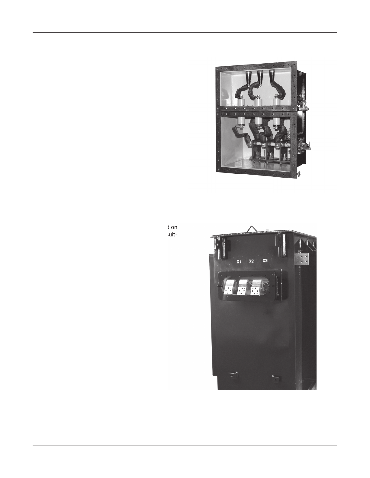
High-Voltage Switch and Terminal Chamber
The high-voltage switch is a uid-immersed rotary type
switch located in the high-voltage switch chamber, with
an adjacent terminal chamber located above. An optional
single-chamber design is available. The switch has three
operating positions, OPEN, CLOSED, and GROUND, clearly
indicated on the switch indicator plate. A mechanical
stop is provided to prevent unintentional operation of the
switch and to allow an electrical interlock to prevent operation if the transformer is energized. Several different
types high-voltage cable entrances are available.
Figure 2: High-Voltage Switch and Terminal Chamber
Network Protector Provisions
A secondary throat and support brackets are provided on
the low-voltage termination side of the tank that are suit-
able for mounting a low-voltage network protector.
Table 1: Factory Testing
Catalog Section 94-10
Network Transformers
Issued: April 9, 2010
Figure 3: Network Protector Provisions
Copyright © 2010 Howard Industries, Inc.
3
Howard Industries, Inc.
Laurel, MS 39440
www.howardtransformers.com
Page 4

Network Transformer94-10
Factory Testing
In addition to numerous quality inspections throughout
the manufacturing process, nal tests are conducted on
the completed network transformer to ensure proper function of all systems. All tests are conducted in accordance
with applicable industry standards. Test equipment is
state-of-the-art and capable of extremely accurate and
reliable test measurements, meeting all the industry loss
measurement standards. All test systems are calibrated
regularly according to industry standards. Calibration of
loss-measuring equipment is NIST traceable.
The following standard and optional production-line tests
are performed. Standard tests are performed on each
completed transformer. Optional tests are performed
upon customer request and at customer expense. Customers may arrange to witness factory testing. All tests
will be made in accordance with the latest revisions of
IEEE C57.12.00 Standard General Requirements for
Liquid-Immersed Distribution, Power, and Regulating
Transformers and IEEE C57.12.90 Standard Test Code for
Liquid-Immersed Distribution, Power and Regulating Transformers and Guide for Short Circuit Testing of Distribution
and Power Transformers.
Quality Assurance
Howard employees understand the importance of quality,
particularly as it relates to network transformer applications. Emphasis on quality begins at design and follows
throughout the manufacturing and delivery processes.
Only the highest quality components and materials are
used in Howard network transformers. Attention to detail
during manufacture, and careful inspection and testing
ensure that a high level of quality is maintained.
Howard’s quality management system is designed to
ensure that all of the company’s products and services
meet or exceed our customers’ requirements and is certi ed by DQS-UL as being compliant with ISO-9001:2008.
The ISO-9001:2008 standard covers design, manufacturing, and servicing systems, and is the most stringent and
comprehensive standard in the internationally recognized
ISO-9000 series of quality standards.
Production-Line Tests
Winding resistance •
Winding insulation resistance (Megger) •
Ratio •
Polarity and phase relation •
Insulation power factor •
No-load losses and excitation current •
Impedance voltage and load losses •
Zero-phase sequence impedence
voltage
Temperature rise •
Low frequency dielectric tests •
Applied potential •
Induced potential •
Lightning impulse •
Front-of-wave impulse •
Audible sound level •
Leak test •
Partial discharge (RIV) •
ANSI impulse test •
Standard
Test
Optional
Test
•
Howard Industries, Inc.
Laurel, MS 39440
www.howardtransformers.com
Copyright © 2010 Howard Industries, Inc.
4
Catalog Section 94-10
Network Transformers
Issued: April 9, 2010
Page 5

Network Transformer
Features and Accessories
94-10
Howard network transformers are available with a wide
range of features and accessories in order to satisfy the
requirements of even the most demanding applications.
Contact the factory or your area sales representative for
the availability of other design options not listed.
Standard Features and Accessories
Howard network transformers are supplied with the following standard features and accessories:
• Self-cooled power ratings (ONAN)—300 kVA through
2,500 kVA, three-phase
• High-voltage rating—from 2.4 kV through 34.5 kV
• High-voltage taps—Per ANSI C57.12.40.
• Low-voltage ratings—through 600 Volts
• BIL levels—Per ANSI C57.12.40
• Excitation limit—Per ANSI C57.12.00
• Average temperature rise—55ºC/65ºC
• Frequency—60 Hertz
• Impedance and impedance tolerance—Per ANSI
C57.12.40
• Audible sound levels—Per ANSI C57.12.40
• Service location—vault-type network transformers are
suitable for installation in above-ground dry vaults
where occasional submersion is possible. Subwaytype network transformers are suitable for installation
in subsurface vaults where frequent or continuous
submersion is likely. Subway type designs are suitable for subway or vault applications.
• Cooling/insulating uid—Type II mineral oil with oxidation inhibitor
• Fluid preservation system—sealed tank
• Main tank—copper-bearing steel construction, with
sub-base, main cover, and the following standard accessories:
− Dial-type magnetic liquid-level indicator (without
alarm contacts) welded to tank
− Dial-type thermometer (without alarm contacts)
− Combination drain and bottom lter valve
− Filling plug and upper lter press connection
− Top liquid sampling plug
− Air test provision
− Grounding pad welded to tank
− Lifting provisions for complete unit
− Lifting provisions for main tank cover
− Cover-mounted, pad-lockable tap changer switch
under protective pipe cap for de-energized operation (on units supplied with high-voltage taps)
− Bolted hand hole cover
− Corrosion-resistant steel fastening hardware
− Secondary throat suitable for mounting network
protector, with mounting holes, guide pins, gasket, and steel plate shipping guard
− Subway-type radiator panels (when required by
design)
− Pressure-relief valve (subway type)
• Primary terminal chamber—sealed enclosure welded
to main tank above the primary switch chamber, with
the following standard accessories:
− Bolted cover with, gasket, guide pins, and lifting
provisions
− Drain plug
− Liquid lling plug
− Liquid level and vent plug
− Three replaceable primary bushings between
terminal chamber and switch chamber, with terminals
− Primary entrance consisting of one of the following two methods: 1) wiping sleeves or 2) deadfront bushing bushings
• Primary switch chamber—sealed enclosure welded to
main tank beneath the primary switch chamber, with
the following accessories:
− Bolted cover with, gasket, guide pins, and lifting
provisions
− Three-pole, three-position, 200 Ampere, noninterrupting high-voltage switch and external
operating handle with latch
− Electrical interlock on switch
− Dial-type magnetic liquid level indicator welded to
chamber (without alarm contacts)
− Liquid lling plug
− Air test provision
− Drain valve
− Mineral oil insulating uid
• Low-voltage termination consisting of the following:
− Three externally replaceable bushings bolted to
the tank within the secondary throat
− Three exible connectors for electrical connection
to a network protector
− Low-voltage neutral connection welded to the
tank
• Paint nish—catalyzed epoxy primer plus catalyzed
urethane enamel topcoat; 3.0 mils nominal dry thickness
• Nameplate—non-corrosive diagrammatic nameplate,
permanently attached with non-corrosive hardware
Catalog Section 94-10
Network Transformers
Issued: April 9, 2010
Copyright © 2010 Howard Industries, Inc.
5
Howard Industries, Inc.
Laurel, MS 39440
www.howardtransformers.com
Page 6

Network Transformer94-10
Optional Features and Accessories
The following optional features and accessories are available. Check with the factory for the availability of other
features and accessories not listed.
• Series-multiple high-voltage winding
• Delta-wye connection
• Special high-voltage taps
• Special low-loss high efciency designs
• Design optimization to lowest total owning cost
• 50 Hertz operating frequency
• Special impedance
• Special sound level
• Special phase relationship
• Special BIL level
• Over excitation capability
• 65° C average temperature rise
• Special ambient temperature
• Operation at altitudes above 3300 feet
• Copper windings
• Core ground test point located inside tank accessible
from bolted handhole
• Electrostatic shields
• Optional tank features and accessories
− Special hardware
− Welded handhole cover
− Additional bolted or welded hand-hole
− Special tank design pressure (up to 15 psig)
− Ground connectors
− Special tank dimensions
− Tank undercoating
− Omit pressure-relief valve
• Optional gauges and ttings
− Dial-type magnetic liquid-level gauge (with alarm
contacts)
− Dial-type thermometer (with alarm contacts)
− Pressure-vacuum gauge (with or without alarm
contacts)
− Automatic pressure-relief device (with or without
alarm contacts)
− Drain valve with liquid sampling valve
− Additional drain valve on tank or switch chamber
− Spare gaskets for secondary throat, bolted hand-
holes, high-voltage terminal chamber, and switch
chamber
− Sight gauge for high-voltage terminal chamber
− Other options (check with factory)
• Optional high-voltage switch features and accessories
− Interrupting switch or other special switches
− Provisions for phase sequence identication
(phasing tubes)
− Phase sequence indication (sequential grounding), including 3 internal grounding contacts,
5-position switch to indicate phase when switch is
moved from transformer positions to ground position
− Additional electrical interlocks
− Viewing windows for observation of switch blades
(with hinged protective cover)
• Optional high-voltage entrance features and accessories
− Single-conductor or multi-conductor wiping
sleeves, or pothead entrance
− Six universal bushing wells for loop feed with or
without loadbreak inserts (HV switch must be
omitted)
− Three integral loadbreak bushings
− Three non-Ioadbreak bushings
− Six non-Ioadbreak bushings for loop feed (HV
switch must be omitted)
− Six integral loadbreak bushings for loop feed (HV
switch must be omitted)
− Three molded bushings mounted on front of
terminal chamber in lieu of the standard wiping
sleeve
− Potheads, one 3-conductor or three 1-conductor,
instead of the standard terminal chamber
− Bottom entrance of HV cable, including wiping
sleeves
− Packing gland or stufng box
− Phase separation barriers in compartment (when
switch is omitted)
− Dielectric uid or compound for terminal chamber
• Optional low-voltage air terminations
− Welded low-voltage bushings
− Fully insulated low-voltage neutral bushing
− Other low-voltage termination options (check with
factory)
• Optional network protector provisions (check with factory)
• Optional dielectric uids
− Silicone uid
− FR3 natural ester-based uid
Howard Industries, Inc.
Laurel, MS 39440
www.howardtransformers.com
Copyright © 2010 Howard Industries, Inc.
6
Catalog Section 94-10
Network Transformers
Issued: April 9, 2010
Page 7

Network Transformer 94-10
Warranty Service and Maintenance
Warranty Service
Should product defects be discovered during the warranty period, immediately contact the factory or your area sales
representative. A warranty claim will be processed, so that any problem can be resolved quickly.
Replacement Parts
Replacement parts can be obtained by contacting the factory or your area sales representative. Be prepared to provide
the transformer serial number, which is located on the transformer’s diagrammatic nameplate.
Catalog Section 94-10
Network Transformers
Issued: April 9, 2010
Copyright © 2010 Howard Industries, Inc.
7
Howard Industries, Inc.
Laurel, MS 39440
www.howardtransformers.com
Page 8

Network Transformer94-10
Network Transformers
Catalog Section 94-10
Document 2.4.85, Revision 0, April 9, 2010
Copyright © 2010 Howard Industries, Inc.
Laurel, Mississippi
Telephone: 601-425-3151
Fax: 601-649-8090
E-mail: mkt@howard.com
Web: howardtransformers.com
 Loading...