

Page 1
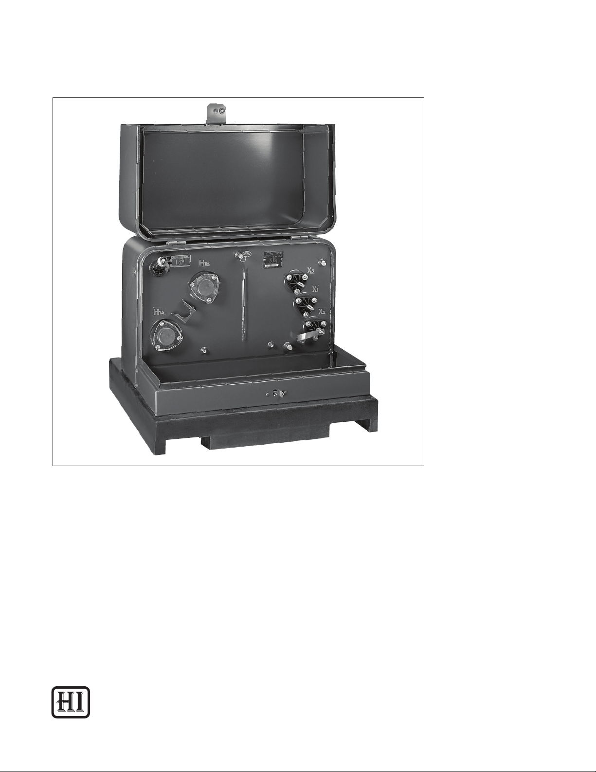
Single-Phase Pad-Mounted Compartmental-Type Distribution Transformers
Document 2.4.96, Revision 0
March, 2013
Instructions (HI-104)
Installation, Operation, and Maintenance of
Single-Phase Pad-Mounted Compartmental-Type
Distribution Transformers
Howard Industries
Distribution Transformer Division
1
Page 2

Document 2.4.96, Revision 0
March, 2013
! READ THIS IMPORTANT SAFETY INFORMATION
▲
READ THIS ENTIRE INSTRUCTION MANUAL CAREFULLY AND BECOME FAMILIAR WITH THE EQUIPMENT AND ALL SAFETY-RELATED INFORMATION BEFORE PROCEEDING WITH INSTALLATION, OPERATION, OR MAINTENANCE ACTIVITIES.
Safe use of this equipment is dependent on proper installation, operation, and maintenance procedures. Follow all applicable local and national codes.
Do not attempt to service or perform maintenance activities on the equipment until it has been effectively de-energized, and all high-voltage and low-voltage bushing terminals have been properly
grounded.
Only qualied personnel should install, maintain, and operate this equipment. Qualied personnel
are those who are trained in the installation, maintenance, and operation of high-voltage equipment,
trained in the proper use of personal protective equipment (PPE) and trained in appropriate rst aid
procedures. Refer to NFPA 70E.
Single-Phase Pad-Mounted Compartmental-Type Distribution Transformers
Do not rely solely on fuse removal or switch position as conclusive indication that a transformer is
de-energized. Be absolutely certain that a transformer is de-energized by checking for zero voltage
on all terminals.
Certain information in this manual is marked with the words DANGER, WARNING, or CAUTION, which
indicate hazards as listed below.
DANGER indicates an imminently hazardous situation which, if not avoided, will result in death
or serious personal injury, and could also result in damage to the equipment.
WARNING indicates a potentially hazardous situation which, if not avoided, could result in
death or serious personal injury, and could also result in damage to the equipment.
CAUTION indicates a potentially hazardous situation which, if not avoided, could result in minor
or moderate personal injury, and could also result in damage to the equipment.
These instructions are intended as a general guide for the installation, operation and maintenance of
the equipment, when operated in “Usual Service Conditions” as dened in IEEE Standard C57.12.00.
Although every effort has been made to ensure accuracy and completeness, these instructions do
not address every conceivable application or circumstance that might be encountered. Howard Industries makes no representation or warranty with respect to, and assumes no responsibility for the
completeness, accuracy, sufciency, or usefulness of, these instructions. Features presented herein
may not be present in all equipment designs. Standard and optional features are subject to change
without notice.
Questions regarding installation, operation, and maintenance of the equipment, particularly when
encountering unusual or special circumstances which may not be sufciently covered by these instructions, should be directed to the Howard Industries Transformer Division.
2
Page 3

Document 2.4.96, Revision 0
Single-Phase Pad-Mounted Compartmental-Type Distribution Transformers
March, 2013
TABLE OF CONTENTS
SECTION 1: INTRODUCTION .......................................................................................................................................... 5
SECTION 2: RECEIVING, HANDLING, AND STORAGE ................................................................................................. 6
Drawings and Documents ....................................................................................................................................... 6
Lifting and Handling ................................................................................................................................................. 6
Initial Inspection ........................................................................................................................................................ 6
Fluid Level .................................................................................................................................................................. 7
Internal Inspection ................................................................................................................................................... 8
Fluid Sampling ........................................................................................................................................................... 8
Transformer Storage ................................................................................................................................................ 8
SECTION 3: INSTALLATION ............................................................................................................................................ 9
Lifting and Handling ................................................................................................................................................. 9
Jacking, Skidding and Rolling .................................................................................................................................. 9
Location and Mounting ............................................................................................................................................ 9
Verifying Enclosure Integrity ................................................................................................................................... 10
Grounding ................................................................................................................................................................ 10
High-Voltage and Low-Voltage Connections .......................................................................................................... 10
High-Voltage Terminals ........................................................................................................................................... 10
Low-Voltage Terminals ............................................................................................................................................ 11
SECTION 4: INSPECTION AND TESTING BEFORE AND AFTER INITIAL ENERGIZATION ......................................12
Pre-Energization Inspection and Tests .................................................................................................................. 12
Ratio Test ................................................................................................................................................................. 12
Insulation Resistance Test...................................................................................................................................... 12
Tap Changer Setting. ............................................................................................................................................... 12
Multiple-Voltage Switch Setting ..............................................................................................................................12
Grounding ................................................................................................................................................................ 12
Bolted Connections. ................................................................................................................................................ 12
Fluid Level ................................................................................................................................................................ 12
Fluid Temperature ................................................................................................................................................... 13
Internal Fault Detector ............................................................................................................................................ 13
Current Transformers. ............................................................................................................................................. 13
Accessory Wiring ..................................................................................................................................................... 13
Tank Finish .............................................................................................................................................................. 13
Tools ......................................................................................................................................................................... 13
Internal Inspection .................................................................................................................................................. 13
Post-Energization Inspection and Tests ................................................................................................................. 13
Verifying Correct Voltage ......................................................................................................................................... 13
Checking for Leaks. ................................................................................................................................................. 14
Observing Operation ............................................................................................................................................... 14
Checking Gauges .................................................................................................................................................... 14
Audible Sound ......................................................................................................................................................... 14
Locking the Terminal Compartment ...................................................................................................................... 14
SECTION 5: OPERATION OF SWITCHING AND PROTECTIVE DEVICES ...................................................................15
Hot-Stick Operable Devices .................................................................................................................................... 16
Tap Changer ............................................................................................................................................................ 16
Multiple-Voltage Switch .......................................................................................................................................... 16
Load-Break Switch .................................................................................................................................................. 16
Fuses ..........................................................................................................................................................................................17
3
Page 4

Document 2.4.96, Revision 0
March, 2013
Internal Weak-Link Fuse ............................................................................................................................................................17
Bay-O-Net Fuse .......................................................................................................................................................................... 18
Dead-Break Dry-Well Canister Fuse ..........................................................................................................................................19
Internal Partial-Range Current-Limiting Fuse .......................................................................................................................... 20
S&C Arc-Strangler ...................................................................................................................................................................... 20
S&C Fused Switch ..................................................................................................................................................................... 20
Surge Arrester ........................................................................................................................................................................... 20
Internal MOV Surge Arrester ..................................................................................................................................................... 20
Low-Voltage Circuit Breaker...................................................................................................................................................... 22
Magnex Interrupter ................................................................................................................................................................... 22
Other Switching and Fusing Devices ........................................................................................................................................ 23
SECTION 6: OPERATION OF TERMINAL COMPARTMENT, BUSHINGS, GAUGES AND ACCESSORY DEVICES ..................... 24
Hot-Stick Operable Devices .......................................................................................................................................................24
Pressure-Vacuum Gauge ...........................................................................................................................................................24
Fluid Level Gauge and Sight Plug .............................................................................................................................................24
Fluid Temperature Gauge .........................................................................................................................................................24
Drain Valve and Sampling Device .............................................................................................................................................24
Automatic Pressure Relief Valve ............................................................................................................................................. 25
Internal Fault Detector ............................................................................................................................................................. 25
High-Voltage Bushings ............................................................................................................................................................. 25
Low-Voltage Bushings .............................................................................................................................................................. 26
Current Transformers ................................................................................................................................................................ 26
Accessory Brackets ................................................................................................................................................................... 26
Terminal Compartment ............................................................................................................................................................. 26
Single-Door Terminal Compartment ........................................................................................................................................ 26
Double-Door Terminal Compartment ........................................................................................................................................27
Other Accessory Devices ...........................................................................................................................................................27
Single-Phase Pad-Mounted Compartmental-Type Distribution Transformers
SECTION 7: MAINTENANCE AND REPAIR .....................................................................................................................................28
Periodic Inspection.................................................................................................................................................................... 28
Inspection Checklist .................................................................................................................................................................. 28
Electrical Tests .......................................................................................................................................................................... 29
Exterior Paint Finish .................................................................................................................................................................. 30
Fluid Leaks ................................................................................................................................................................................ 30
Audible Sound Level.................................................................................................................................................................. 30
Low-Voltage Circuit Breaker.......................................................................................................................................................31
Magnex Interrupter ....................................................................................................................................................................31
Other Accessory Devices ...........................................................................................................................................................31
Sampling and Testing the Fluid ................................................................................................................................................31
Filtering the Fluid .......................................................................................................................................................................31
Removing or Lowering the Fluid ................................................................................................................................................31
Filling with Fluid .........................................................................................................................................................................31
Opening the Transformer Tank ................................................................................................................................................ 32
Torque Guidelines ..................................................................................................................................................................... 33
Additional Maintenance Instructions ...................................................................................................................................... 34
Repair Parts .............................................................................................................................................................................. 34
Warranty Claims ....................................................................................................................................................................... 34
Tables
Table 1: Torque Guidelines for External Cabinet Fasteners .................................................................................33
Table 2: Torque Guidelines for External Bushing Mounting Hardware ................................................................ 33
Table 3: Torque Guidelines for External Bushing Terminal Connections ............................................................. 33
Table 4: Torque Guidelines for Accessories ........................................................................................................... 34
4
Page 5

Single-Phase Pad-Mounted Compartmental-Type Distribution Transformers
SECTION 1: INTRODUCTION
Document 2.4.96, Revision 0
March, 2013
This document is intended as a general guide for the
installation, operation and maintenance of Howard
Industries uid-lled, single-phase, pad-mounted
compartmental-type distribution transformers.
Although every effort has been made to ensure
accuracy and completeness, these instructions
do not address every conceivable application or
circumstance that might be encountered. Features
presented herein may not be present in all
transformer designs. Standard and optional features
are subject to change without notice.
These instructions are applicable to single-phase,
pad-mounted compartmental-type distribution
transformers (including IEEE Type 1, IEEE Type 2 and
other styles covered by IEEE Standards C57.12.25
and C57.12.38, and the Space-Saver™ style), which
are designed as a single-door style with a one-piece
ip-top hood, or the double-door style (sometimes
called a “wardrobe-style” transformer), which is
designed with two hinged access doors.
All transformer styles are designed for mounting
outdoors on a concrete pad or other suitable
surface. High-voltage and low-voltage cables enter
the transformer terminal compartment from below
ground through an opening in the mounting pad.
The instructions contained herein are applicable
to transformers operated in usual conditions as
specied in the “Usual Service Conditions” section
of IEEE Standard C57.12.00. Questions regarding
installation, operation, and maintenance (particularly
when encountering unusual or special circumstances
not sufciently covered by these instructions) should
be directed to the Howard Industries Transformer
Division.
IT IS IMPORTANT TO READ AND COMPLY WITH ALL
SAFETY INFORMATION AND WARNINGS DISPLAYED
THROUGHOUT THESE INSTRUCTIONS BEFORE
ATTEMPTING ANY INSTALLATION, OPERATION, OR
MAINTENANCE ACTIVITIES.
5
Page 6

Document 2.4.96, Revision 0
March, 2013
SECTION 2: RECEIVING, HANDLING, AND STORAGE
Single-Phase Pad-Mounted Compartmental-Type Distribution Transformers
Drawings and Documents
Locate all shipping papers, packing lists,
specications, and other pertinent information for
use during inspection. Verify that the transformer is
supplied with a nameplate, required warning labels,
and terminal designation markings. Verify that the
terminal designation markings are consistent with
those on the nameplate. The transformer nameplate
provides electrical characteristics, winding
connections, and weights. The transformer wiring
diagram provides details of any control, fan and
alarm wiring that may have been provided.
Lifting and Handling
Lifting lugs or bosses are provided to lift the
completely assembled transformer. All lifting lugs
or bosses must be used simultaneously to provide
a safe, balanced lift. The transformer must not be
lifted from any points other than the provided lifting
lugs or bosses. Do not use holes in the lifting hooks
for lifting. These holes are for tie-down purposes
only and are not suitable for lifting. Refer to the
transformer nameplate to determine the total weight
of the assembled transformer.
Lifting bosses, when provided, consist of 5/8”-11
threaded inserts. Lifting should be accomplished
with user-installed 5/8”-11 lifting bolts that have
been fully engaged into the threaded bosses and
hoist rings. Do not lift with lifting bolts alone. Lifting
bolts and hoist rings must be rated to safely support
the weight of the completely assembled transformer.
A spreader bar should be used to keep the lifting
cables or straps nearly vertical, enabling a safe lift
and reducing the likelihood of tank deformation or
damage to painted surfaces. Transformers should be
lifted in an upright position, allowing the transformer
to tilt no more than 15 degrees from vertical. Lifting
cables or straps should be no more than 20 degrees
from vertical.
Single-door style transformers may also be lifted with
a forklift truck of adequate lifting capacity to safely
handle the weight of the completely assembled
transformer. Forks should be of sufcient length to
extend completely through the shipping pallet or
runners. Transformers should be lifted with the tank
(core/coil and uid compartment) oriented toward
the forklift truck, so that the transformer center of
gravity is adequately supported. Lifting transformers
from the terminal compartment side is not safe, as
the transformer may tip and fall.
Lifting double-door style transformers with a forklift
truck is not recommended, since weight and balance
can be problematic, and radiator panels can be
easily damaged.
Transformers should be handled with special care
when the ambient temperature is below minus 20°C
(minus 4°F); otherwise, permanent damage to the
transformer may result.
!
▲
WARNING
FAILURE TO FOLLOW THE INSTRUCTIONS
BELOW COULD RESULT IN DEATH OR SERIOUS
PERSONAL INJURY, AND COULD ALSO RESULT
IN DAMAGE TO THE EQUIPMENT.
• Lifting equipment, including forklift trucks,
cranes, hoists, cables, straps, lifting bolts,
hoist rings and spreader bars, must be of
adequate capacity to safely lift the completely
assembled transformer.
• Keep unnecessary personnel clear while
unloading and moving the transformer.
Initial Inspection
Although all transformers, components, and
accessories are carefully inspected and tested prior
to shipment from the factory, a thorough receiving
inspection should be conducted to detect any
damage or loss that might have occurred during
shipment. The receiving inspection should be
completed upon receipt and before unloading from
the truck. Note any damage or discrepancies on the
bill of lading, le a claim with the carrier, and notify
the Howard Industries Transformer Division prior to
unloading the transformer and before attempting any
repair.
6
Page 7

Single-Phase Pad-Mounted Compartmental-Type Distribution Transformers
Document 2.4.96, Revision 0
March, 2013
Before unloading the transformer, the following
checks should be performed:
1. Read the serial number on the transformer
nameplate and make sure it matches
the serial number listed on the shipping
documents. Also, check the nameplate
for kVA rating, high-voltage rating, lowvoltage rating, impedance and other design
characteristics, and make sure they comply
with the specications.
2. Check shipping documents to make sure
the shipment is complete, including all listed
accessories and hardware. Be aware that
additional items may arrive on separate
pallets. Claims for shortages or errors
must be noted on the shipping documents
and reported immediately to the Howard
Industries Transformer Division. Failure
to make a timely claim will constitute
unqualied acceptance and a waiver of all
such claims by the purchaser.
3. The tank vacuum/pressure gauge, when
provided, may indicate a positive or negative
reading when the transformer is received,
depending on the relative temperatures of
the uid and ambient air. A rising or falling
reading that varies over time with ambient
temperature indicates that the transformer
tank is sealed effectively. If the vacuum/
pressure gauge shows a constant zero
reading, this indicates the possibility of a
tank leak. If this occurs, the tank should be
checked carefully for leaks as indicated in
the following step.
4. Check the tank for indication of uid leaks,
looking carefully at weld seams, bushings,
gauges, valves and all other tank ttings. If
suspicious indications are found, investigate
thoroughly to determine if a leak does
exist on the transformer. Indications of a
leak can sometimes be residual uid that
was not cleaned during the manufacturing
process and not an actual leak. In many
cases a small pinhole tank leak or leak
from a bushing, gauge, valve or other tting
can be easily repaired on site. Refer to
the “Maintenance and Repair” section for
information about the repair of uid leaks.
5. Check for external damage including dents
or scratches on the tank walls, radiators and
terminal compartment. Dents and scratches
can often be repaired on site using simple
touch-up procedures. If touch-up painting
is performed, do not remove or obscure
any warning labels, instructional labels or
nameplates.
6. Check for broken, cracked, or damaged
bushings, gauges, valves and other ttings
and accessories.
7. Check for missing or damaged component
parts and for packages that shipped
separately from the transformer.
Fluid Level
The transformer is shipped from the factory with
insulating uid lled to the proper level. Before
energizing the transformer, verify proper uid level
by observing the uid level gauge, if provided. The
uid level gauge pointer should be between the
“High” and “Low” marks. For transformers provided
with a uid sight plug, the uid level can be directly
observed if it is within acceptable range. If the
transformer does not have a uid level gauge or sight
plug, the uid level can be checked by removing
the liquid level plug located at the 25°C mark. Prior
to removing the ll plug, relieve tank pressure by
operating the PRV, being careful to avoid any hot
uid that might be expelled from the valve. Exercise
caution when checking the uid level using the
uid level plug, as the uid may spill out and may
be extremely hot. When reinstalling the ll plug,
apply a suitable sealing compound to the threads to
ensure a proper seal. When checking the uid level,
be aware that the level will vary as a function of uid
temperature.
A transformer found to have a low uid level should
be checked for potential leaks and lled to the
proper level with the same type of liquid as that
specied on the transformer nameplate. Refer to
“Filling with Fluid.”
7
Page 8

Document 2.4.96, Revision 0
March, 2013
! WARNING
▲
FAILURE TO FOLLOW THE INSTRUCTIONS
BELOW COULD RESULT IN DEATH OR SERIOUS
PERSONAL INJURY, AND COULD ALSO RESULT
IN DAMAGE TO THE EQUIPMENT.
• Do not energize the transformer if the uid
level is low.
• Maintain proper uid level at all times while
the transformer is energized.
• Exercise caution when checking the uid level
with the uid level plug, as the uid may spill
and may be extremely hot.
Internal Inspection
An internal inspection of the transformer tank is
rarely necessary and is recommended only when
there are obvious indications that the transformer
has received severe impact damage during transit
or when necessary to perform recommended preenergization tests or inspections. Do not open
the transformer tank without authorization from
the Howard Industries Transformer Division. If the
transformer tank must be opened, refer to “Opening
the Transformer Tank” for instructions.
Single-Phase Pad-Mounted Compartmental-Type Distribution Transformers
Transformers should be stored on a rm level
surface. They may also be stored in racks designed
for that purpose. Transformers should not be stacked
directly on top of one another, as this may damage
the paint nish and cause cabinet misalignment.
It is recommended that the transformer be inspected
periodically while it is in extended storage. Ensure
that an effective pressure seal is maintained, and
check for leaks and corrosion. Any damage or
defects should be repaired immediately.
Fluid Sampling
Sampling and testing of the uid is not required
unless there is indication that moisture or other
contaminants have accidently entered the tank
during transit. If moisture or contaminants in the
uid is suspected, contact the Howard Industries
Transformer Division immediately for instructions.
If uid sampling is required, refer to “Sampling the
Fluid” for instructions.
Transformer Storage
Transformers may be temporarily stored if properly
prepared. It is recommended that transformers
be stored completely assembled. Prior to storage,
transformers should be thoroughly inspected as
described above in the “Initial Inspection” section.
If the transformer is not completely assembled,
separate components and accessories should be
stored in a clean dry area in their original shipping
containers. Do not store the transformer in a
corrosive environment.
8
Page 9

Single-Phase Pad-Mounted Compartmental-Type Distribution Transformers
SECTION 3: INSTALLATION
Lifting and Handling
Lifting lugs or bosses are provided to lift the
completely assembled transformer. All lifting lugs
or bosses must be used simultaneously to provide
a safe, balanced lift. The transformer must not be
lifted from any points other than the provided lifting
lugs or bosses. Do not use holes in the lifting hooks
for lifting. These holes are for tie-down purposes
only and are not suitable for lifting. Refer to the
transformer nameplate to determine the total weight
of the assembled transformer.
Lifting bosses, when provided, consist of 5/8”-11
threaded inserts. Lifting should be accomplished
with user-installed 5/8”-11 lifting bolts that have
been fully engaged into the threaded bosses and
hoist rings. Do not lift with lifting bolts alone. Lifting
bolts and hoist rings must be rated to safely support
the weight of the completely assembled transformer.
A spreader bar should be used to keep the lifting
cables or straps nearly vertical, enabling a safe lift
and reducing the likelihood of tank deformation or
damage to painted surfaces. Transformers should be
lifted in an upright position, allowing the transformer
to tilt no more than 15 degrees from vertical. Lifting
cables or straps should be no more than 20 degrees
from vertical.
Single-door style transformers may also be lifted
with a forklift truck of adequate lifting capacity to
safely handle the weight of the completely assembled
transformer. Forks should be of sufcient length to
extend completely through the shipping pallet or
runners. Transformers should be lifted with the tank
(core/coil and uid compartment) oriented toward the
forklift truck, so that the transformer center of gravity
is adequately supported. Lifting transformers from
the terminal compartment side is not safe, as the
transformer may tip and fall.
Lifting double-door style transformers with a forklift
truck is not recommended, since weight and balance
can be problematic, and radiator panels can be easily
damaged.
Transformers should be handled with special care
when the ambient temperature is below minus 20°C
(minus 4°F); otherwise, permanent damage to the
transformer may result.
FAILURE TO FOLLOW THE INSTRUCTIONS BELOW
COULD RESULT IN DEATH OR SERIOUS PERSONAL INJURY AND COULD ALSO RESULT IN DAMAGE TO THE EQUIPMENT.
• Lifting equipment, including forklift trucks,
• Keep unnecessary personnel clear while
Jacking, Skidding and Rolling
Double-door style transformers are designed for
jacking, skidding and rolling. Do not use radiator ns,
bushings, valves, pipe ttings, gauges or sheet metal
surfaces for jacking. Jacking must be done using
the proper jacking provisions from two adjacent
corners simultaneously to prevent warping of the
tank bottom. When rolling, use an adequate number
of rollers to distribute the transformer weight evenly.
Refer to the transformer outline drawing for the total
weight of the assembled transformer.
Location and Mounting
Consult local and national codes to ensure that
the installation meets all applicable requirements.
Location of the transformer must permit it to operate
in conditions that meet the requirements specied
in the “Usual Service Conditions” section of IEEE
Standard C57.12.00 General Requirements for
Liquid-Immersed Distribution, Power and regulating
Transformers. Operation not meeting these service
condition requirements will compromise transformer
capacity and reliability, unless the transformer is
designed specically for operation in conditions
other than usual service conditions. Contact the
Howard Industries Transformer Division, if additional
information is needed about location and mounting
issues not covered by these instructions
The transformer should be mounted on a level
concrete foundation or other suitable surface, which
is rated to support the weight of the completely
Document 2.4.96, Revision 0
! WARNING
▲
cranes, cables, straps, lifting bolts, hoist
rings and spreader bars, must be of adequate capacity to safely lift the completely
assembled transformer.
unloading and moving the transformer.
March, 2013
9
Page 10

Document 2.4.96, Revision 0
March, 2013
Single-Phase Pad-Mounted Compartmental-Type Distribution Transformers
assembled transformer. The transformer should sit
ush with the mounting surface, so that there are no
gaps that might compromise tamper resistance of
the terminal compartment. The installed transformer
should not tilt in any direction more than three
degrees. Greater tilt may compromise insulating
uid coverage of live parts within the tank and may
prevent insulating uid from circulating properly
through the cooling radiators. Improper circulation of
insulating uid may cause overheating and reduced
transformer life.
The transformer should be located at least 24 inches
from any obstruction and have adequate clearance
to allow the terminal compartment hood or doors to
open fully. Avoid locating the transformer in corrosive
areas. Remove any shipping braces and packing
material that may have been installed at the factory.
Hold-down cleats or brackets should be used to
securely fasten the transformer to the mounting
surface.
Verifying Enclosure Integrity
Howard single-phase compartmental-type padmounted transformers are designed and constructed
to be tamper resistant according to the requirements
of IEEE Standard C57.12.28 Pad-Mounted
Equipment—Enclosure Security, or C57.12.29 Pad-
Mounted Equipment—Enclosure Security for Coastal
Environments, as applicable, and therefore need not
be installed in a restricted area. Do not modify the
tank or terminal compartment in such a way that it
will compromise tamper resistance. If for any reason
modications must be made to the tank or terminal
compartment that compromise tamper resistance,
the transformer must then be located in a restricted
area. Such modications of may void the warranty.
Consult with the Howard Industries Transformer
Division before making any modications to the
transformer.
! WARNING
▲
FAILURE TO FOLLOW THE INSTRUCTIONS
BELOW COULD RESULT IN DEATH OR SERIOUS
PERSONAL INJURY, AND COULD ALSO RESULT
IN DAMAGE TO THE EQUIPMENT.
Do not modify the transformer in any way that
might compromise its tamper-resistant construction.
Grounding
The transformer must be permanently grounded
according to applicable local and national codes.
Ground the transformer by using ground pads or
nuts located inside the terminal compartment at
the base of the front panel. Do not use hold-down
bolts, pipe connections or any other ttings for
ground connections. A proper low-resistance ground
connection is necessary for safe operation.
In addition to proper tank grounding as stated above,
transformers designed for use on a grounded-wye
system must also have all winding neutrals securely
and effectively grounded to the system neutral.
! WARNING
▲
FAILURE TO FOLLOW THE INSTRUCTIONS
BELOW COULD RESULT IN DEATH OR SERIOUS
PERSONAL INJURY, AND COULD ALSO RESULT
IN DAMAGE TO THE EQUIPMENT.
The transformer must be properly grounded at
all times.
High-Voltage and Low-Voltage Connections
Before making high-voltage and low-voltage line
connections, check to make sure that all mating
connector surfaces are clean and smooth.
Connections must be tightened appropriately to
prevent overheating and possible failure of the
connection. Refer to the nominal torque guidelines
contained in Table 3. Connections should be made
with care to avoid placing undue cantilever stress on
the bushings.
High-Voltage Terminals
Dead-front transformers are designed to use the
separable insulated high-voltage connector system
dened in IEEE Standard 386. These dead-front
transformers come equipped with universal bushing
wells only, one-piece (integral) bushings or universal
bushing wells with factory-installed bushing inserts.
Either loadbreak-rated or non-loadbreak-rated
bushings can be provided as specied by the user.
When transformers are provided with universal
bushing wells only, bushing inserts must be installed
in the eld by the user before cable connections can
be made. Bushing well inserts must be compatible
10
Page 11

Single-Phase Pad-Mounted Compartmental-Type Distribution Transformers
with the universal bushing wells. Do not use
incompatible or improperly rated bushing inserts,
or equipment damage could occur. When installing
inserts, follow the manufacturer’s instructions
accompanying the inserts. Insulated dead-end caps
or plugs must be installed on all unused high-voltage
bushings before energizing. Shipping dust caps must
never be used in place of insulated dead-end caps or
plugs.
Live-front transformers are equipped with highvoltage bushings having tin-plated eye-bolt or spade
terminals that are suitable for connection with either
aluminum or copper conductors to the high-voltage
source.
Low-Voltage Terminals
Single-phase pad-mounted transformers are usually
provided with externally-clamped, molded, lowvoltage bushings, with or without NEMA standard
spade terminals. When threaded terminals are
installed, a backup nut should be installed and
tightened against the terminal to ensure an
adequate connection that will not loosen or overheat.
Secondary line leads should be securely attached to
the terminals to ensure a low-resistance connection.
Document 2.4.96, Revision 0
March, 2013
Space-Saver™ style transformers may be provided
with a block-mounted, wire-lead, low-voltage
termination instead of molded bushings. These wire
leads are designed to be crimp-connected to the
load leads.
11
Page 12

Document 2.4.96, Revision 0
March, 2013
SECTION 4: INSPECTION AND TESTING BEFORE AND
Single-Phase Pad-Mounted Compartmental-Type Distribution Transformers
AFTER INITIAL ENERGIZATION
Pre-Energization Inspection and Tests
After the transformer has been installed, but before
it is energized, the following tests and checks should
be performed at a minimum to ensure that the
transformer is ready to be energized. Do not energize
the transformer without performing these tests and
checks.
! DANGER
▲
FAILURE TO FOLLOW THE INSTRUCTIONS
BELOW WILL RESULT IN DEATH OR SERIOUS
PERSONAL INJURY, AND COULD ALSO RESULT
IN DAMAGE TO THE EQUIPMENT.
Be aware of dangerous voltages within the terminal compartment and avoid personal contact
with live terminals.
! WARNING
▲
FAILURE TO FOLLOW THE INSTRUCTIONS
BELOW COULD RESULT IN DEATH OR SERIOUS
PERSONAL INJURY, AND COULD ALSO RESULT
IN DAMAGE TO THE EQUIPMENT.
• Only qualied personnel with appropriate
equipment should measure transformer voltages.
• Wear personal protective equipment (PPE)
to prevent injury from potential arc-ash or
contact with dangerous voltages.
• Make sure the transformer is securely and
effectively grounded at all times.
• Insulated dead-end caps or plugs must be
installed on all unused dead-front high-voltage bushings. Dust caps must not be used in
place of insulated dead-end caps or plugs.
• Current transformer (CT) leads must be connected to a metering load or shorted together
and grounded to prevent dangerous voltage
at the CT terminals.
• After successful completion of the recom-
mended tests and checks, energize the transformer from a remote location.
1. Ratio Test—Using a transformer turns ratio tester
(TTR), perform a ratio test to verify the primaryto-secondary winding ratio. The measured value
should be within 0.5% of the voltage ratio indicated on the transformer nameplate. If the
transformer is provided with high-voltage taps,
measure the ratio at each tap position to ensure that each of the ratios is correct. Follow the
instructions and safety precautions provided by
the TTR equipment manufacturer. For additional
information about ratio testing, refer to IEEE
Standard C57.12.90.
2. Insulation Resistance Test—Perform a 1,000-Volt
insulation test (Megger test) to measure the resistance of the insulation between windings and
from each winding to ground. Follow the instructions and safety precautions provided by the test
equipment manufacturer. Prior to the test, bushings must be thoroughly cleaned with denatured
alcohol to remove any moisture or contaminants
that could inuence the test results. Measured
resistance should be at least 1.0 GΩ.
3. Tap Changer Setting—On transformers pro-
vided with taps, check the tap changer setting
to ensure it is set to the proper position for the
required voltage.
4. Multiple-Voltage Switch Setting—On transform-
ers provided with a multiple-voltage switch,
check the switch setting to make sure it is set to
the correct position.
5. Grounding—Check to ensure that the transformer
tank is securely and effectively grounded. The
transformer tank ground pad is located inside
the terminal compartment near the bottom of the
tank.
6. Bolted Connections—Check all bolted connec-
tions for tightness, referring to nominal torque
guidelines contained in Tables 1 through 4.
7. Fluid Level—Check to make sure the uid level
is correct as indicated by the uid level gauge or
sight plug. If the transformer does not have a uid level gauge or sight plug, the uid level can be
checked by temporarily removing the liquid-level
plug located at the 20°C mark. Prior to removing
the plug, relieve tank pressure by operating the
12
Page 13

Single-Phase Pad-Mounted Compartmental-Type Distribution Transformers
Document 2.4.96, Revision 0
March, 2013
pressure relief valve, being careful to avoid any
hot uid that might be expelled from the valve.
When reinstalling the plug, apply an appropriate
thread sealing compound to prevent a uid leak.
Be aware that uid temperature and orientation
of the transformer tank will cause the uid level
to vary. Transformers are lled to a level that
corresponds to a uid temperature of 25°C. The
actual uid level will increase with increasing
temperature. The uid level indication will also
vary when the transformers is not installed in a
level orientation.
8. Fluid Temperature—Observe the uid tempera-
ture gauge and make sure the temperature is
no lower than indicated below before the unit is
energized.
-20°C (-4°F) for conventional transformer oil
and silicone uid
0°C (32°F) for R-Temp uid
-10°C (14° F) for natural ester uid
9. Internal Fault Detector—If the transformer is
provided with an Internal Fault Detector (IFD),
remove the red shipping lock after installation
and before placing the transformer into service.
10. Current Transformers—If current transformers
(CTs) are present, connect CT leads to the metering load. If CT leads are not connected to a metering load, they must be shorted together and
grounded before the transformer is energized.
11. Accessory Wiring—Check wiring of control and
alarm circuits (if provided) to make sure there
are no loose connections and no damage to wire
insulation.
12. Tank Finish—Check all painted surfaces to make
sure that there is no damage or corrosion.
13. Tools—Check to make sure that all tools and
equipment are accounted for.
14. Internal Inspection— Transformer tanks are
sealed at the factory and should not be opened
unless necessary. Single-door style transformer
tanks are fully welded and are not accessible
except through bushing openings. Double-door
style transformer tanks are accessible through
a bolted handhole located on the tank cover. If
the transformer tank must be accessed, refer to
“Opening the Transformer Tank” for instructions.
Post-Energization Inspection and Tests
After the transformer is energized, the following tests
and inspections should be performed.
! DANGER
▲
FAILURE TO FOLLOW THE INSTRUCTIONS
BELOW WILL RESULT IN DEATH OR SERIOUS
PERSONAL INJURY, AND COULD ALSO RESULT
IN DAMAGE TO THE EQUIPMENT.
Be aware of dangerous voltages within the terminal compartment and avoid personal contact
with live terminals.
! WARNING
▲
FAILURE TO FOLLOW THE INSTRUCTIONS
BELOW COULD RESULT IN DEATH OR SERIOUS
PERSONAL INJURY, AND COULD ALSO RESULT
IN DAMAGE TO THE EQUIPMENT.
• Energize the transformer from a remote location.
• Only qualied personnel with appropriate
equipment should measure transformer voltages.
• Wear personal protective equipment (PPE)
to prevent injury from potential arc-ash or
contact with dangerous voltages.
• Make sure the transformer is securely and
effectively grounded at all times.
• Insulated dead-end caps or plugs must be
installed on all unused dead-front high-voltage bushings. Dust caps must not be used in
place of insulated dead-end caps or plugs.
• Current transformer (CT) leads must be connected to a metering load or shorted together
and grounded to prevent dangerous voltage
at the CT terminals.
1. Verifying Correct Voltage—Before supplying volt-
age from the transformer to the load, verify that
the secondary voltage is correct. Using a suitable
AC voltmeter, measure the voltage of the secondary windings and make sure they agree with
the secondary voltage listed on the transformer
nameplate.
13
Page 14

Document 2.4.96, Revision 0
March, 2013
2. Checking for Leaks—Check the tank to make
sure there are no uid leaks.
3. Observing Operation—After the transformer is
initially energized, visually inspect it periodically,
to make sure that no abnormal conditions are
observed.
4. Checking Gauges—Observe the uid level and
uid temperature gauges, if provided, to conrm
the proper uid level and temperature.
Single-Phase Pad-Mounted Compartmental-Type Distribution Transformers
5. Audible Sound—
It is normal for transformers
to emit an audible humming sound, which is
primarily caused by alternating magnetic ux in
the transformer core. Amplitude and harmonic
content of the sound is inuenced by transformer
size, the energizing voltage level and sinusoidal
purity, load conditions and acoustic conditions
at the installation site. Refer to NEMA Standards
Publication TR-1 Transformers, Regulators and
Reactors, and IEEE Standard C57.12.90 IEEE
Standard Test Code for Liquid-Immersed Distribution, Power, and Regulating Transformers, for
more information about design sound levels, and
factory sound testing. Unusual sounds should be
investigated, as this might indicate a potential
problem.
Locking the Terminal Compartment—Before leaving
the installation site, make sure the terminal compartment is secure. Follow the procedures the “Single-
Door Terminal Compartment” or “Double-Door Terminal Compartment” section, as applicable.
14
Page 15

Single-Phase Pad-Mounted Compartmental-Type Distribution Transformers
SECTION 5: OPERATION OF SWITCHING AND PROTECTIVE DEVICES
The following operating instructions and descriptions
of switching and fusing devices are intended to be a
general guide for operation of Howard single-phase
pad-mounted transformers in normal environments.
Although every effort has been made to ensure accuracy and completeness, these instructions and
descriptions do not address every conceivable application or circumstance that might be encountered.
Personnel should read and comply with any safety
and instructional labels that might accompany any
accessory device.
Some of the accessory devices described below are
optional and may not be present in any particular
transformer design. The inclusion of particular accessory devices in any transformer design is governed
by industry standards and by individual customer
specications.
FAILURE TO FOLLOW THE INSTRUCTIONS
BELOW COULD RESULT IN DEATH OR SERIOUS
PERSONAL INJURY, AND COULD ALSO RESULT
IN DAMAGE TO THE EQUIPMENT.
• Do not operate load-break equipment if a
• Use a live-line tool (hot stick or shotgun stick)
• After operating transformer loadbreak equip-
Document 2.4.96, Revision 0
! WARNING
▲
fault condition is suspected.
to operate transformer load-break equipment. Do not attempt to operate by hand any
device that is designed to be operated with a
live-line tool.
ment, check that voltages at transformer
terminals are the expected values. Checking
voltages veries that loadbreak equipment
operated properly and that electrical circuit
conditions are as expected.
March, 2013
• Before servicing the transformer, always
de-energize the transformer from a remote
location and then proceed to ground all
primary and secondary transformer terminals
following industry-accepted safe grounding
practices. Grounding secondary terminals
protects against situations such as a standby
generator energizing transformer from the
secondary circuit.
• Follow industry accepted-safety practices.
Utilize personal protective equipment (PPE)
when working with this equipment.
• Do not operate uid-immersed load-break
fusing and switching devices when the insulating uid temperature is below the following
limits:
-20°C (-4°F) for conventional transform-
er oil and silicone uid
0°C (32°F) for R-Temp uid
-10°C (14°F) for natural ester uid
15
Page 16
Document 2.4.96, Revision 0
March, 2013
Single-Phase Pad-Mounted Compartmental-Type Distribution Transformers
Hot-Stick Operable Devices
Some devices such as draw-out expulsion fuses,
dry-well canister fuses, dead-front high-voltage elbow
terminations, rotary load-break switches and automatic pressure relief valves are designed to be operated with a live-line tool (hot stick or shotgun stick).
Do not attempt to operate by hand any device that is
designed to be operated with a live-line tool. Inspect,
test and operate the live-line tool according to the instructions provided by the live-line tool manufacturer.
Tap Changer
The de-energized tap changer may be used to adjust
the voltage ratio of a transformer while it is de-energized. It is intended to allow adjustment of the output (secondary) voltage to the rated value. Do not
use the tap changer to alter the output voltage to any
voltage other than that indicated on the transformer
nameplate. If the tap changer is set to provide an
output voltage other than the rated secondary voltage, improper transformer operation could occur.
! WARNING
▲
FAILURE TO FOLLOW THE INSTRUCTIONS
BELOW COULD RESULT IN DEATH OR SERIOUS
PERSONAL INJURY, AND COULD ALSO RESULT
IN DAMAGE TO THE EQUIPMENT.
• Do not operate a de-energized tap changer
unless the transformer is totally de-energized.
• Do not re-energize the transformer unless the
tap changer handle or cap is secured in the
desired position.
Tap changers usually have ve or seven tap positions
as indicated on the tap changer dial plate and the
transformer nameplate. A locking screw is provided
on the operating handle to lock the tap changer into
position and prevent accidental operation.
Prior to operating the tap changer on a de-energized
transformer, disengage the locking screw and then
rotate the handle to the desired tap position. Never
operate a tap changer while the transformer is energized. Do not re-energize the transformer until the
tap changer is set to the desired tap position, and
the locking screw has been engaged.
The transformer is usually shipped from the factory
with the tap changer set to the rated voltage position, unless otherwise specied by the customer.
Always check the tap changer position to make sure
it is set correctly.
Multiple-Voltage Switch
Transformers designed with multiple high-voltage
windings (dual-voltage or triple-voltage transformers)
are provided with a de-energized multiple-voltage
switch. The switch, if provided, will be indicated on
the transformer nameplate.
The transformer must be completely de-energized
before operating the multiple-voltage switch. Unless
otherwise specied, multiple-voltage transformers
are shipped from the factory with the multiple-voltage switch set to the highest voltage position.
! WARNING
▲
FAILURE TO FOLLOW THE INSTRUCTIONS
BELOW COULD RESULT IN DEATH OR SERIOUS
PERSONAL INJURY, AND COULD ALSO RESULT
IN DAMAGE TO THE EQUIPMENT.
• Do not operate a de-energized multiple-voltage switch unless the transformer is completely de-energized.
• Do not re-energize the transformer unless
the multiple-voltage switch handle or cap is
secured in the desired position.
Load-Break Switch
The optional rotary load-break switch is located
inside the terminal compartment. The switch can
be designed as a two-position ON-OFF switch, or a
three- or four-position sectionalizing switch. Switch
positions are marked on the transformer front panel
and shown on the nameplate diagram. Load-break
switches are designed to be operated with a live-line
tool (hot stick or shotgun stick) and should not be
operated by hand.
The two-position load-break switch is operated by
inserting the live-line tool into the operating handle
and rotating the switch to either the ON or OFF position. The three-position or four-position load-break
switch is operated by inserting the live-line tool in
the index plate and moving the plate over the peg
16
Page 17

Single-Phase Pad-Mounted Compartmental-Type Distribution Transformers
Document 2.4.96, Revision 0
March, 2013
between its present setting and the next setting. The
index plate prevents the switch from switching more
than one position at a time. The live-line tool is then
inserted into the switch operating handle and turned
until the switch snaps into the next position. Repeat
this procedure until the switch is in the desired position. Do not stop and reverse direction of the switch
before it has changed position, as this will damage
the switch mechanism.
! CAUTION
▲
FAILURE TO FOLLOW THE INSTRUCTIONS BELOW COULD RESULT IN MINOR OR MODERATE
PERSONAL INJURY, AND COULD ALSO RESULT
IN DAMAGE TO THE EQUIPMENT.
• Do not operate a load-break switch by hand.
Operate only using a live-line tool (hot stick or
shotgun stick).
• Do not stop and reverse direction of the loadbreak switch before it has changed positions.
Fuses
A blown fuse may indicate a faulted transformer. Do
not replace a blown fuse unless the cause of the
fuse operation has been identied and corrected.
Replacement fuses should have the appropriate rating and operating characteristics. Refer to the circuit
diagram on the transformer nameplate for the location of fuses.
Internal Weak-Link Fuse
An internal weak-link fuse (also called a cartridge
fuse) is a uid-immersed expulsion fuse, which is
designed to isolate the transformer from the distribution system in the event of an internal fault on the
load side of the fuse. On single-door style transformers the fuse can usually be accessed by removing
one of the high-voltage bushings. On double-door
style transformers, the fuse is accessible through the
cover-mounted handhole. Refer to the transformer
nameplate for the fuse location. When accessing the
fuse, observe the precautions discussed in “Opening
the Transformer Tank.”
On single-door style transformers the fuse can be
usually be inspected and replaced through the front
panel using the following procedure.
1. Make sure that the transformer is completely deenergized and that the tank and all primary and
secondary terminals are securely and effectively
grounded.
2. Vent the tank by operating the pressure relief
valve, being careful to avoid contact with any hot
uid that might be expelled from the PRV.
3. Tilt the transformer to the rear, so that the internal uid level drops below the bushing opening.
Alternatively, the uid level can be lowered to
replace the fuse Refer to “Removing or Lowering
the Fluid.”
4. Remove the bushing clamping hardware and remove the bushing and fuse, taking care to avoid
stress on the high-voltage coil lead.
! WARNING
▲
FAILURE TO FOLLOW THE INSTRUCTIONS
BELOW COULD RESULT IN DEATH OR SERIOUS
PERSONAL INJURY, AND COULD ALSO RESULT
IN DAMAGE TO THE EQUIPMENT.
• Do not replace a blown fuse unless the cause
of the fuse operation has been identied and
corrected.
• De-energize the transformer and ground all
terminals before replacing fuses.
• Only qualied personnel with appropriate
measurement devices should measure the
voltages on the transformer.
5. Unbolt the fuse and replace it with a new fuse of
the appropriate rating. Tighten the fuse mounting
fasteners according to the recommended torque
values in Table 4.
6. Clean the bushing mounting surface and inspect
the bushing gasket. Replace the gasket if damaged.
7. Insert the fuse and bushing into the mounting
hole and install mounting hardware. Tighten
mounting fasteners according to the recommended torque guidelines in Table 4.
8. Level the transformer, re-attach hold-down cleats
or brackets if previously removed, and check to
make sure the bushing is not leaking uid.
9. Energize the transformer from a remote location
and check for proper operation.
17
Page 18

Document 2.4.96, Revision 0
March, 2013
Single-Phase Pad-Mounted Compartmental-Type Distribution Transformers
On double-door style transformers the fuse can be
inspected and replaced through the cover-mounted
handhole using the following procedure.
1. Make sure that the transformer is completely deenergized and that the tank and all primary and
secondary terminals are securely and effectively
grounded.
2. Vent the tank by operating the pressure relief
valve, being careful to avoid any hot uid that
might be expelled from the PRV.
3. Remove the tank hand-hole cover.
4. Identify the fuse block assembly.
5. Remove leads attached to each end of the cartridge fuse, being careful not to drop any nuts or
washers into the tank.
6. Unbolt the fuse and replace it with a new fuse of
the appropriate rating. Tighten the fuse mounting
fasteners according to the recommended torque
values in Table 4.
7. Re-install the tank hand-hole cover. Refer to
“Opening the Transformer Tank” for instructions.
Bay-O-Net Fuse
The optional Bay-O-Net is a uid-immersed, drawout, dead-front fused disconnect device that is rated
for load-break operation. It is designed to be operated with a live-line tool (hot stick or shotgun stick)
and should not be operated by hand. The Bay-O-Net
device is located in the terminal compartment near
the high-voltage bushings. The Bay-O-Net is available as an expulsion fuse device or as a full-range
current-limiting fuse device. Personnel should read
and follow the instructions provided by the Bay-O-Net
device manufacturer for proper operating procedures
and safety information.
The Bay-O-Net is designed to provide protection for
the transformer and the distribution system and
is not intended as a disconnect device for routine
transformer operation. The Bay-O-Net does not
provide a visible disconnect and should not be relied
on as the sole indication that the transformer is deenergized.
When the Bay-O-Net is provided as an expulsion fuse
device, it is equipped with a series-connected uidimmersed isolation link, or if specied by the customer, a series-connected partial-range current-limiting
fuse. Isolation links and partial-range current-limiting fuses are designed to blow in the event of an
internal transformer fault. A transformer with a blown
isolation link or partial-range current-limiting fuse
cannot be re-energized and must be removed from
service.
! WARNING
▲
FAILURE TO FOLLOW THE INSTRUCTIONS
BELOW COULD RESULT IN DEATH OR SERIOUS
PERSONAL INJURY, AND COULD ALSO RESULT
IN DAMAGE TO THE EQUIPMENT.
• Bay-O-Net fuse devices are not recommended for fault closing. The Bay-O-Net device
should not be used to re-energize a transformer that is suspected to be faulted.
• Operate the pressure relief valve to vent pressure in the transformer tank before unlatching a Bay-O-Net device to prevent hot oil from
being expelled during fuse removal. Be careful to avoid hot uid that might be expelled
from the PRV.
• Operate the Bay-O-Net device with a live-line
tool (hot stick or shotgun stick). Never operate the Bay-O-Net device by hand.
• After replacing a blown fuse, the transformer
should be re-energized from a remote location.
• Never rely of Bay-O-Net removal as the sole
indication that the transformer is de-energized.
The following procedures are intended as a general
guide for operation of the Bay-O-Net device. Personnel should also read and follow the instructions
provided by the Bay-O-Net device manufacturer for
proper operating procedures and safety information.
On single-door style transformers open the ip-top
hood and secure it in the open position. On doubledoor style transformers open both compartment
doors and engage the prop rods on each door to
latch them in the open position.
Remove Fuse Holder—The following procedure
should be used to withdraw the fuse holder from the
Bay-O-Net housing.
18
Page 19

Single-Phase Pad-Mounted Compartmental-Type Distribution Transformers
Document 2.4.96, Revision 0
March, 2013
1. Vent the transformer by operating the PRV. Keep
the valve open until the sound of air venting can
no longer be heard. Be careful to avoid contact
with any hot oil that might be expelled from the
PRV.
2. Stand to one side of the Bay-O-Net device being
operated.
3. Attach a live-line tool to the holder eye.
4. Twist the live-line tool to unlock the fuse holder.
5. Rotate the holder 90 degrees clockwise in the
housing to break the seal between the gasket
and the housing.
6. Firmly and quickly pull the fuse holder out about
8 to 10 inches to open the circuit. Wait a few
seconds while the uid drains back into the tank,
and then completely withdraw the fuse holder.
Wipe the fuse holder and cartridge to remove
excess uid.
7. If uid continues to ow from the Bay-O-Net
device, operate the pressure relief valve again to
vent pressure from the tank.
Replace Fuse Link—Replace the fuse according to
the manufacturer’s instructions included with the
replacement fuse.
break load and must only be operated when the
transformer is de-energized. When specied, dry-well
canisters are mechanically interlocked with a loadbreak switch to prevent removal of the fuses while
the transformer is energized
! WARNING
▲
FAILURE TO FOLLOW THE INSTRUCTIONS
BELOW COULD RESULT IN DEATH OR SERIOUS
PERSONAL INJURY, AND COULD ALSO RESULT
IN DAMAGE TO THE EQUIPMENT.
• Do not operate a dead-break canister fuse
device while the transformer is energized.
• After replacing a blown current-limiting fuse,
the transformer should be re-energized from
a remote location.
The following procedures are intended as a general
guide for operation of the canister fuse device. Personnel should also read and follow the instructions
provided by the canister fuse device manufacturer
for proper operating procedures and safety information.
Re-Insert Fuse Holder—Re-insert the fuse holder using the following procedure.
1. Using a live-line tool attached to the eye of the
fuse holder, re-insert the holder rmly into the
Bay-O-Net housing.
2. Twist the locking handle, latching it to the shoulder of the Bay-O-Net housing. Make sure that
the metal washer is positioned tightly on the end
of the Bay-O-Net housing.
3. Inspect the fuse holder carefully to make sure it
is fully seated and latched properly.
Dead-Break Dry-Well Canister Fuse
The optional dead-break dry-well canister is a uidtight current-limiting fuse holder. It is designed to be
operated with a live-line tool (hot stick or shotgun
stick) and should not be operated by hand. The drywell canister is mounted on the transformer front
panel near the high-voltage bushings.
Dead-break dry-well canisters are not designed to
Remove Fuse Holder—The following procedures
should be used to remove the fuse holder.
1. Make sure the transformer is de-energized.
2. Attach a live-line tool to the hook eye.
3. Quickly pull the fuse holder assembly completely
from the housing.
Replace Fuse—The fuse should be replaced using
the following procedure.
1. Unscrew the fuse from the fuse holder.
2. Replace with new fuse of the appropriate rating
and characteristics.
3. Tightly screw the new fuse onto the fuse holder.
Re-Insert Fuse Holder—Re-insert the fuse holder using the following procedure.
1. Attach a live-line tool to the hook eye.
2. Insert the fuse holder into the housing.
3. Push the fuse holder in rmly until the dust cap
seats against the housing and grounding clip.
19
Page 20

Document 2.4.96, Revision 0
March, 2013
Single-Phase Pad-Mounted Compartmental-Type Distribution Transformers
Internal Partial-Range Current-Limiting Fuse
The optional internal partial-range (backup) currentlimiting fuse is connected in series with a low-current
interrupting device, such as a weak-link cartridge
fuse or a Bay-O-Net expulsion fuse. The partial-range
current-limiting fuse is designed to clear low impedance (high current) faults, while expulsion fuses are
designed to clear a high impedance fault or overload.
When properly applied, the partial-range currentlimiting fuse will operate only for internal transformer
faults. When a partial-range current-limiting fuse has
blown, the transformer should be considered faulted
and removed from service.
S&C Arc-Strangler
The optional S&C Arc-Strangler is a 200 Ampere,
air-insulated, load-break device that is designed to
be operated with a live-line tool (hot stick or shotgun
stick) and should never be operated by hand. The
Arc-Strangler device may include a full-range current-limiting fuse on the switch blade or a clip-style
current-limiting fuse.
The following procedures are intended as a general
guide for operation of the Arc Strangler device. Personnel should also read and follow the instructions
provided by S&C for proper operating procedures and
safety information. To operate the switch, insert the
live-line tool in the operating hook and pull forward,
swinging the Arc-Strangler open. To remove the ArcStrangler, insert the live-line tool in the hinge opening and lift up.
! WARNING
▲
FAILURE TO FOLLOW THE INSTRUCTIONS
BELOW COULD RESULT IN DEATH OR SERIOUS
PERSONAL INJURY, AND COULD ALSO RESULT
IN DAMAGE TO THE EQUIPMENT.
• Arc-Strangler devices are not recommended
for fault closing. Arc-Strangler devices should
not be used to re-energize a transformer that
is suspected to be faulted.
• Operate Arc-Strangler device with a live-line
tool (hot stick or shotgun stick). Never operate by hand.
• After replacing a blown fuse, the transformer
should be re-energized from a remote location.
S&C Fused Switch
The optional S&C fused switch should be operated
according to instructions provided by S&C. S&C tools
should be used to operate an S&C fused switch.
Surge Arrester
The optional surge arrester is used to protect the
transformer and underground cable from damage
due to voltage surges. A surge arrester should be
installed only on systems where the power frequency
voltage at the arrester does not exceed the arrester’s
published maximum continuous operating voltage
(MCOV) value.
! WARNING
▲
FAILURE TO FOLLOW THE INSTRUCTIONS
BELOW COULD RESULT IN DEATH OR SERIOUS
PERSONAL INJURY, AND COULD ALSO RESULT
IN DAMAGE TO THE EQUIPMENT.
• De-energize the transformer from a remote
location and make sure all transformer terminals and bushings have zero voltage before
connecting or servicing surge arresters.
• Disconnect all surge arresters before performing impulse, induced-potential or applied-potential tests.
Disconnect the surge arrester before performing
impulse, induced-potential or applied-potential tests;
otherwise, the arrester may be damaged. Reconnect
the surge arrester after testing and before placing
the transformer back into service.
Internal MOV Surge Arrester
The internal metal-oxide-varister (MOV) surge arrester is designed to be uid immersed and mounted
inside the transformer tank. It is recommended that
the uid-immersed MOV arrester not be exposed to
an average oil temperature exceeding 90°C (194°F)
and a maximum oil temperature exceeding 125°C
(257°F).
Disconnect the uid-immersed MOV surge arrester
before performing impulse, induced-potential or
applied-potential tests; otherwise, the arrester may
be damaged. Reconnect the surge arrester after testing and before placing the transformer into service.
20
Page 21

Single-Phase Pad-Mounted Compartmental-Type Distribution Transformers
Document 2.4.96, Revision 0
March, 2013
An optional arrester disconnector provides a means
to disconnect the uid-immersed MOV arrester
ground for transformer testing without entering the
transformer tank. Two different styles of disconnectors are available, one manufactured by ERMCO
Components Inc. (ECI) and one manufactured by
Cooper Power Systems (CPS). These two styles operate differently as indicated below.
Before testing the transformer, disconnect the arrester using the following procedure.
1. Make sure the transformer tank is properly
grounded.
2. De-energize the transformer from a remote location.
3. Ground all bushings and terminals.
4. Disconnect the MOV arrester by operating the
disconnector as described below.
For the CPS disconnector (identied by an
external black plastic cap):
a. Unscrew the black disconnector
cap from the shaft.
b. Re-attach the small diameter end
of the disconnector cap to the
shaft.
c. Push the handle and shaft toward
transformer until the shaft ange
is ush to the sealing gland.
For the CPS disconnector:
a. Pull the disconnector handle and shaft
fully away from transformer.
b. Unscrew the black disconnector cap
and re-attach it with the large diameter end toward the transformer. Rotate
the cap clockwise to tighten.
c. Reinstall the black cap.
For the ECI disconnector:
a. Push the shaft inward until the
threads engage.
b. Tighten the 7/16” square head ac-
cording to the torque guidelines listed
in Table 4.
On double-door style transformers the arrester
disconnector may not be provided, and the uidimmersed MOV arrester must be manually disconnected before testing by opening the transformer
tank. Refer to “Opening the Transformer Tank” for
instructions.
The MOV arrester can be manually disconnected using the following procedure.
1. Make sure that tank is properly grounded.
2. De-energize the transformer from a remote location.
3. Ground all bushings and terminals.
For the ECI disconnector (identied by a
7/16” square brass metal head):
a. Unscrew the 7/16” square metal
head until the thread disengages.
b. Pull the shaft out to its full extent
(approximately 2”).
5. It is now safe to perform impulse, induced-potential or applied-potential tests.
After testing the transformer, reconnect the MOV arrester using the following procedure.
1. Make sure the tank is properly grounded.
2. De-energize the transformer from a remote location.
3. Ground all bushings and terminals.
4. Reconnect the MOV arrester by operating the
disconnector as described below.
4. Relieve pressure inside the tank by operating the
pressure relief valve, being careful to avoid any
hot uid that might be expelled from the valve.
5. Remove the tank cover.
6. Locate the disconnect point to which the arrester
line lead is attached.
7. Disconnect the arrester lead from its junction
point and isolate the lead end at least six inches
from any other part of the transformer.
8. It is now safe to perform impulse, induced-potential or applied-potential tests.
The following procedure should be followed to manually reconnect the arrester lead.
1. Reconnect the arrester lead to its junction point
using the hardware previously removed.
2. Re-install the tank cover.
21
Page 22

Document 2.4.96, Revision 0
March, 2013
Single-Phase Pad-Mounted Compartmental-Type Distribution Transformers
Low-Voltage Circuit Breaker
The optional low-voltage circuit breaker is mounted
inside the tank and is uid immersed. The breaker
uses an automatic trip system to help protect the
transformer from damage caused by overloads and
short circuits. The presence of a low-voltage circuit
breaker will be indicated on the transformer nameplate.
! WARNING
▲
FAILURE TO FOLLOW THE INSTRUCTIONS
BELOW COULD RESULT IN DEATH OR SERIOUS
PERSONAL INJURY, AND COULD ALSO RESULT
IN DAMAGE TO THE EQUIPMENT.
• Do not rely solely on the circuit breaker to
de-energize the transformer secondary. Always ground the secondary terminals before
performing work.
• Even with the circuit breaker in the OPEN
position, there may be sufcient capacitive
coupling to cause a shock hazard at the secondary terminals.
• Operate the low-voltage circuit breaker with
a live-line tool (hot stick or shotgun stick).
Never operate by hand.
The circuit breaker may be provided with an optional
emergency overload capability. The emergency
overload lever is located adjacent to the main operating handle. To provide continued service during an
overload situation, rotate the emergency overload
lever to temporarily raise the breaker trip setting.
Rotation of the lever is variable, so that more or less
overload capability can be selected. Overload operation should be minimized to prevent excessive loss of
transformer life. When shipped from the factory, the
emergency overload lever is secured with a meter
seal to prevent accidental operation.
Magnex Interrupter
The optional Magnex Interrupter is an over-current
protective device and load-break switch, which is
internally mounted under oil and connected into the
high-voltage circuit of the transformer. The interrupter coordinates with an internal protective link or
internal current-limiting fuse, so that the interrupter
operates rst for overloads or faults on the load side
of the transformer. The presence of a Magnex Interrupter will be indicated on the transformer nameplate. The following procedures are intended as a
general guide for operation of the Magnex Interrupter. Personnel should read and follow Cooper Power
Systems Magnex Interrupter Installation Instructions
S340-34-1.
The circuit breaker is a thermal trip device provided
for transformer protection. It is not intended as a
disconnect device for routine transformer operation.
The circuit breaker does not provide a visible disconnect and should not be relied on as the sole indication that the secondary is de-energized. The circuit
breaker operating handle is located in the terminal
compartment near the low-voltage bushings and
is designed to be operated with a live-line tool (hot
stick), as follows.
— To open the circuit breaker, rotate the
handle so that the pointer is at the OPEN
(“O”) position.
— To close the circuit breaker, rotate the
handle, so that the pointer is at the
CLOSED (“C”) position.
— To reset the circuit breaker after it has
tripped, rotate the handle, so that the
pointer is at the RESET (“R”) position.
Then rotate the handle, so that the
pointer is at the CLOSED (“C”) position.
The operating handle is located in the terminal
compartment and is designed to be operated with a
live-line tool (hot stick), as follows.
− To open the interrupter, rotate the handle
upward in a counterclockwise direction,
until the spring-loaded contacts open and
the handle is in the OPEN position.
− To close the interrupter, rotate the handle
downward in a clockwise direction, until
the handle is against the physical stop
in the CLOSED position. When in the
CLOSED position, the interrupter will operate automatically due to an over-current
condition or rise in oil temperature.
− To reset the interrupter after it has
tripped, rotate the handle upward in a
counterclockwise direction to the OPEN
position, and then downward in a clockwise direction, until the handle is against
the physical stop in the CLOSED position.
22
Page 23

Single-Phase Pad-Mounted Compartmental-Type Distribution Transformers
Document 2.4.96, Revision 0
March, 2013
An optional trip indicator is available, consisting of
an indicator lens which appears orange when the
interrupter is in the TRIPPED position.
Some Magnex Interrupters are supplied with an
optional emergency overload setting. The emergency
overload will allow approximately 30% overload before tripping. Using a live-line tool (hot stick), operate
the emergency overload as follows.
− To enable emergency overload, rotate
the handle upward in a counterclockwise
direction, until the handle is in the OPEN
position. Next, turn the emergency overload lever counterclockwise to the EO position. Then rotate the handle downward
in a clockwise direction, until the handle
is in the CLOSED position.
− To disable emergency overload, rotate
the handle upward in a counterclockwise
direction, until the handle is in the OPEN
position. Next, turn the emergency overload lever clockwise to the NORMAL position. Then rotate the handle downward in
a clockwise direction, until the handle is
in the CLOSED position.
Other Switching and Fusing Devices
Transformers may be provided with switching and
fusing devices not discussed in these instructions. In
such cases contact the Howard Industries Transformer Division or the device manufacturer for instructions.
The Magnex Interrupter does not provide a visible
disconnect and should not be relied on as the sole
indication that the transformer secondary terminals
are de-energized.
! WARNING
▲
FAILURE TO FOLLOW THE INSTRUCTIONS
BELOW COULD RESULT IN DEATH OR SERIOUS
PERSONAL INJURY, AND COULD ALSO RESULT
IN DAMAGE TO THE EQUIPMENT.
• Do not rely solely on the Magnex interrupter
to de-energize the transformer secondary. Always ground the secondary terminals before
performing work.
• Operate the Magnex Interrupter with a liveline tool (hot stick or shotgun stick). Never
operate by hand.
• Do not operate the Magnex Interrupter if
there is evidence of tank distress or leaking.
• The handle must be rotated fully against the
stop in the CLOSED position.
23
Page 24

Document 2.4.96, Revision 0
March, 2013
Single-Phase Pad-Mounted Compartmental-Type Distribution Transformers
SECTION 6: OPERATION OF TERMINAL COMPARTMENT, BUSHINGS, GAUGES AND
ACCESSORY DEVICES
Some of the devices described below are optional
and may not be present in any particular transformer
design. The inclusion of particular accessory devices
in any transformer design is governed by industry
standards and by individual user specications.
Hot-Stick Operable Devices
Some devices such as draw-out expulsion fuses,
dry-well canister fuses, dead-front high-voltage elbow
terminations, rotary load-break switches and automatic pressure relief valves are designed to be operated with a live-line tool (hot stick or shotgun stick).
Do not attempt to operate by hand any device that is
designed to be operated with a live-line tool. Inspect,
test and operate the live-line tool according to the instructions provided by the live-line tool manufacturer.
Pressure-Vacuum Gauge
The pressure-vacuum gauge is a dial-type instrument that indicates the pressure in the tank gas
space relative to atmospheric pressure. The gauge is
mounted on the front panel in the terminal compartment above the uid level. Pressure in the tank will
normally vary as a function of transformer and ambient temperatures. If the transformer is lightly loaded
or de-energized during times of low ambient temperature, the gauge may indicate a negative pressure.
The pressure-vacuum gauge may be provided with
optional switch contacts, which can be used to provide a remote alarm.
! WARNING
▲
FAILURE TO FOLLOW THE INSTRUCTIONS BELOW
COULD RESULT IN DEATH OR SERIOUS PERSONAL INJURY, AND COULD ALSO RESULT IN DAMAGE TO THE EQUIPMENT.
If the pressure-vacuum gauge constantly reads
zero under varying load and ambient conditions,
the transformer should be checked for a possible
tank leak. A leak will allow moisture and air to
enter the transformer tank, which could degrade
the paper insulation and insulating uid. Left
unrepaired, a leak could limit transformer life or
cause a violent failure.
Fluid Level Gauge and Sight Plug
The optional uid level gauge is a dial-type device
that indicates the uid level inside the transformer
tank. The gauge is mounted on the front panel in
the terminal compartment at the normal 25°C uid
level.
If the gauge reads “LOW,” the cause of the low reading should be investigated and corrected. A low uid
level can cause overheating of the transformer and
can compromise the insulation system.
The uid level gauge may be provided with optional
switch contacts, which can be used to provide a remote alarm of low uid level. Transformers may also
be provided with an optional sight plug instead of a
gauge to allow direct observation of the uid level.
Fluid Temperature Gauge
The optional uid temperature gauge is a dial-type
bi-metal instrument that indicates the uid temperature at the top of the uid column. The temperature
gauge is mounted on the front panel in a dry leakproof well, permitting removal of the gauge without
exposure to the tank uid.
The gauge may be furnished with a red drag-hand
pointer that indicates the maximum temperature
reached since it was last reset. The drag-hand can
be reset by rotating the magnet at the center of the
dial or, on some types, by pressing a reset button.
The uid level gauge may also be provided with
switch contacts, which can be used to provide a
remote alarm or to energize a fan control circuit.
During normal operation the uid temperature
gauge should read less than the sum of the ambient
temperature and the rated temperature rise (usually
85°C rise). Refer to IEEE Standard C57.91 Guide for
Loading Mineral-Oil-Immersed Transformers for loading recommendations.
Drain Valve and Sampling Device
The optional drain valve and sampling device permits
draining the transformer uid and sampling the uid
for testing purposes. The valve is located in the terminal compartment at the bottom of the front panel.
24
Page 25

Single-Phase Pad-Mounted Compartmental-Type Distribution Transformers
Refer to “Sampling and Testing the Fluid” for the uid
sampling.
Document 2.4.96, Revision 0
! WARNING
▲
March, 2013
Automatic Pressure Relief Valve
The automatic pressure relief valve (PRV) is designed
to relieve excessive tank pressure that might occur
during normal operation of the transformer. The
valve consists of a self-resealing, spring-loaded diaphragm. Some PRV types may include a re-settable
visual ag to indicate that the valve has operated.
When gas pressure in the tank exceeds the PRV’s
specied limit, the gas pressure will cause the valve
to open, venting the excess pressure. After the
internal pressure decreases below the PRV reseal
rating, the valve will automatically close and reseal
the transformer. For PRV’s equipped with a visual
indicating ag, the ag must be manually reset.
When specied, PRV’s are provided with optional
switch contacts, which can be used to provide a
remote alarm.
! WARNING
▲
FAILURE TO FOLLOW THE INSTRUCTIONS
BELOW COULD RESULT IN DEATH OR SERIOUS
PERSONAL INJURY, AND COULD ALSO RESULT
IN DAMAGE TO THE EQUIPMENT.
The cause of PRV activation should always be investigated, since pressure venting may indicate
a potential problem inside the transformer.
Internal Fault Detector
The optional Internal Fault Detector (IFD) is a mechanical sensor that activates when sudden pressure from an internal arcing fault occurs inside
the transformer. If an internal fault occurs, the IFD
releases a visible, non-resettable orange signal ag.
This signal ag alerts crews that the transformer is
faulted and should not be re-energized. Be aware
that the IFD is not a disconnect device. It provides
only a visual indication that an internal fault has occurred. Personnel should read and follow the instructions provided by the IFD device manufacturer for
proper operating procedures and safety information.
FAILURE TO FOLLOW THE INSTRUCTIONS
BELOW COULD RESULT IN DEATH OR SERIOUS
PERSONAL INJURY, AND COULD ALSO RESULT
IN DAMAGE TO THE EQUIPMENT.
• Do not re-energize a transformer if the IFD
has operated.
• Do not attempt to reset the orange signal
ag.
• Always assume that a transformer might be
faulted, even if the IFD has not operated.
• Never rely solely on the IFD as an indicator of
transformer condition.
• The IFD is a visual indicator only. It is not an
electrical disconnect device, and should not
be relied on as such.
The IFD also includes a standard pressure relief
valve that is integrated into the sensor to relieve
excessive tank pressures that might occur during
normal operation of the transformer. The valve can
be operated manually using the pull-ring.
The IFD incorporates a removable shipping lock for
transportation and storage. The shipping lock must
be removed after transformer installation. Always
transport IFD-equipped transformers with the shipping lock installed to prevent accidental operation of
the device.
High-Voltage Bushings
Single-phase pad-mounted transformers with deadfront construction are provided with externallyclamped universal bushing wells only, one-piece
(integral) bushings or universal bushing wells with
factory-installed bushing inserts. One-piece bushings and bushing inserts are designed to interface
with separable insulated elbow connectors, and can
be provided as either load-break or non load-break
devices. When transformers are provided with bushing wells only, inserts must be installed by the user
before cable connections can be made. High-voltage
terminations may be congured for radial feed (one
termination) or loop feed (two terminations).
Single-phase pad-mounted transformers with live-
25
Page 26

Document 2.4.96, Revision 0
March, 2013
front construction are usually provided with externally-clamped porcelain high-voltage bushings for
connection to the high-voltage source. Bushings are
usually provided with tin-plated eye-bolt terminals
that are suitable for connection to either aluminum
or copper conductors.
Single-Phase Pad-Mounted Compartmental-Type Distribution Transformers
! WARNING
▲
FAILURE TO FOLLOW THE INSTRUCTIONS
BELOW COULD RESULT IN DEATH OR SERIOUS
PERSONAL INJURY, AND COULD ALSO RESULT
IN DAMAGE TO THE EQUIPMENT.
! WARNING
▲
FAILURE TO FOLLOW THE INSTRUCTIONS
BELOW COULD RESULT IN DEATH OR SERIOUS
PERSONAL INJURY, AND COULD ALSO RESULT
IN DAMAGE TO THE EQUIPMENT.
Do not place excessive cantilever load on a lowvoltage or high-voltage bushing.
Low-Voltage Bushings
Single-phase pad-mounted transformers are usually provided with externally-clamped molded lowvoltage bushings, with or without spade terminals.
When threaded terminals are installed, a backup nut
should be installed and tightened against the terminal to ensure an adequate connection that will not
loosen or overheat. Secondary line leads should be
securely attached to the terminal to ensure a lowresistance connection and prevent overheating.
Space-Saver™ transformers may be provided with
block-mounted wire-lead low-voltage leads. These
should be crimped to the secondary line leads using
the appropriate crimp connectors and crimping tool.
Follow instructions provided by the crimping tool
manufacturer.
Current Transformers
Optional current transformers (CT’s) are designed to
be mounted around each low-voltage line terminal
for metering applications. Transformers are shipped
from the factory with CT leads shorted together and
grounded. If the CT’s are not connected to a metering load, they must remain shorted and grounded to
avoid hazardous voltage at the CT secondary terminations.
CT leads must be connected to a metering load
or short-circuited and grounded before the transformer is energized to avoid hazardous voltage
at the CT terminals.
Accessory Brackets
An accessory bracket (parking stand) is provided on
dead-front construction, located inside the terminal
compartment near the high-voltage bushings. This
bracket is used as a mounting location for portable
feed-through bushings, insulated standoff bushings
and other similar accessory devices. Follow accessory manufacturer’s instructions for mounting and
using any accessory devices.
Terminal Compartment
Single-phase pad-mounted compartmental-type
transformers are designed and constructed to be
tamper resistant according to the requirements of
IEEE Standards C57.12.28 or C57.12.29, as applicable, and as such are provided with an enclosed
terminal compartment, a penta-head security bolt
and provision for a padlock. Standard penta-head
sockets can be obtained from Snap-On Company
(P/N B2191) or from other tool distributors.
Single-Door Terminal Compartment
The single-door style pad-mounted transformer is
designed with a terminal compartment consisting of
hinged ip-top hood and base sill. The hood can be
opened after removing the padlock and disengaging
the penta-head security bolt. The hood can be completely removed when in the fully-open position.
Before leaving the installation site, make sure the
terminal compartment is closed and secure, using
the following procedure.
26
− Close the ip-top hood.
− Fully engage the penta-head security bolt.
− Install a suitable heavy-duty padlock.
− Carefully check the transformer to make
Page 27

Single-Phase Pad-Mounted Compartmental-Type Distribution Transformers
Document 2.4.96, Revision 0
March, 2013
sure the cabinet is secure and tamper
proof. Make sure the transformer and sill
are sitting ush on the mounting pad with
no gaps that might allow entry of a foreign
object into the terminal compartment.
Double-Door Terminal Compartment
The double-door style pad-mounted transformer is
designed with a terminal compartment consisting of
a terminal compartment cover, two hinged doors and
a base sill. The secondary-side door can be opened
by removing the padlock, disengaging the pentahead security bolt and rotating the door handle. The
primary-side door may be fastened with one or more
security bolts, which must be disengaged to open the
door. Latch rods located at the bottom of each door
can be used to secure doors in the open position.
The double-door style pad-mounted transformer may
also be equipped with a ip-top terminal compartment cover, which can be raised to facilitate operation of the optional Bay-O-Net fuse and to provide
clearance for pulling cables into the terminal compartment. To open the cover, disengage the center
security bolt and rotate the cover upward. A latch is
provided to secure the cover in the open position.
Other Accessory Devices
Transformers may be provided with accessory devices not discussed in these instructions. In such cases
contact the Howard Industries Transformer Division if
additional information is needed.
Lift-off door hinges are provided on double-door style
pad-mounted transformers, so that the compartment
doors can be removed when in the open position.
Before leaving the installation site, make sure the
terminal compartment is closed and secure, using
the following procedure.
− Close the ip-top cover, if present.
− Close the primary compartment door and
engage each security bolt.
− Close the secondary compartment door
and turn the handle to the closed position. Fully engage the secondary compartment door security bolt.
− Install a suitable heavy-duty padlock.
− Carefully check the transformer to make
sure the cabinet appears to be secure
and tamper proof. Make sure the transformer and sill are sitting ush on the
mounting pad with no gaps that might
allow entry of a foreign object into the
terminal compartment.
27
Page 28

Document 2.4.96, Revision 0
March, 2013
Single-Phase Pad-Mounted Compartmental-Type Distribution Transformers
SECTION 7: MAINTENANCE AND REPAIR
These instructions are intended as a general guide
for the maintenance of Howard single-phase padmounted distribution transformers, when used in
typical applications and operated in normal environments. Although every effort has been made to
ensure accuracy and completeness, these instructions do not address every conceivable application or
circumstance that might be encountered.
! WARNING
▲
FAILURE TO FOLLOW THE INSTRUCTIONS
BELOW COULD RESULT IN DEATH OR SERIOUS
PERSONAL INJURY, AND COULD ALSO RESULT
IN DAMAGE TO THE EQUIPMENT.
• De-energize transformer from a remote
location before performing any inspection or
maintenance work.
• Make sure all transformer terminals and
bushings have zero voltage.
• Make sure that the transformer is properly
grounded.
• Fluid leaks should be repaired as soon as
they are discovered.
Periodic Inspection
Transformers should be inspected periodically while
in service, with the frequency determined by service
conditions. Transformers operating in unusual service conditions should be inspected more frequently.
Refer to IEEE Standard C57.12.00 for a discussion of
usual and unusual service conditions.
Accessories such as pressure relief valves, temperature gauges, uid level gauges, pressure-vacuum
gauges and drain valves typically require no maintenance, except replacement in the event of malfunction or damage. Gauges should be checked periodically to make sure they are operating properly.
Inspection Checklist
Observing the safety instructions above, open the
terminal compartment and perform the following
checks.
1. De-energize the transformer and ground all terminals
2. Inspect for dents or other damage to metal surfaces and make the necessary repairs.
3. Inspect the cabinet for evidence of tampering
and immediately repair any damage to ensure
cabinet integrity and prevent unauthorized entry.
4. Inspect the paint nish for damage, corrosion or
weathering that exposes the primer coat or bare
metal. Repair any paint damage that might be
found. Refer to “Exterior Paint Finish” for instructions.
5. Inspect all surfaces thoroughly for evidence of
uid leaks, including tank, radiators, bushings,
gauges, switches, valves, fuse holders and all
other accessories and ttings. Check the uid
level gauge or sight glass (if either of these is
present) to determine the uid level. Check the
pressure-vacuum gauge (if present) for a zero
reading, which indicates the possibility of a tank
leak. The pressure-vacuum gauge may indicate
zero occasionally, but normally indicates a slight
positive or negative pressure, as a function
of uid and ambient temperatures. Perform a
pressure test according to the instructions in the
“Pre-Energization Inspection and Tests” section.
Add uid as necessary to ensure that the proper
uid level is maintained. Repair as necessary.
Fluid leaks should be repaired immediately to
prevent serious damage to the transformer and
an unsafe operating condition. Refer to “Fluid
Leaks” for instructions.
6. Visually check all gaskets for cracking or other
signs of deterioration, and replace as necessary.
When replacing a gasket, carefully clean mating
surfaces to remove any rust, dirt, transformer
uid, old gasket material, or other contamination
that might prevent a good seal. Use appropriate
gasket cement when installing new gaskets. Do
not reuse old gaskets. Six months after replacing a gasket, check and re-tighten, if necessary.
7. Maintain a clean and unobstructed area around
the transformer, including sufcient clearance
around radiator panels, to ensure adequate cooling of the transformer.
8. Inspect the base of the transformer tank and
terminal compartment and make sure that there
is no accumulated dirt or other debris that might
promote corrosion.
28
Page 29

Single-Phase Pad-Mounted Compartmental-Type Distribution Transformers
Document 2.4.96, Revision 0
March, 2013
9. Inspect the base of the terminal compartment
and make sure that it is sitting level and at on
the mounting pad with no gaps that might compromise tamper-resistance.
10 Check bushings, gauges, switches, fuse holders,
valves and all other accessories for proper operation and repair or replace any defective devices.
11. Check all fasteners for signs of corrosion and
replace as necessary.
12. Check to make sure the uid level is correct as
indicated by the uid level gauge or sight plug,
if provided. Be aware that uid temperature and
orientation of the transformer tank will cause
the uid level to vary. Transformers are lled to
a level that corresponds to a uid temperature
of 25°C. The actual uid level will increase with
increasing temperature. The uid level indication will also vary when the transformers is not
installed in a level orientation. If the uid level is
low, add uid according to the instructions in the
“Filling with Fluid” section.
Transformers. For transformers lled with sili-
cone uid, contact the Howard Industries Transformer Division for testing recommendations.
Electrical Tests
The following electrical tests can be used to determine the condition of the transformer. Follow the
instructions and precautions provided by the test
equipment manufacturer. Contact the Howard Industries Transformer Division to discuss any of these
tests.
! DANGER
▲
FAILURE TO FOLLOW THE INSTRUCTIONS
BELOW WILL RESULT IN DEATH OR SERIOUS
PERSONAL INJURY, AND COULD ALSO RESULT
IN DAMAGE TO THE EQUIPMENT.
• Be aware of dangerous voltages and avoid
personal contact with live terminals.
13. Check the uid temperature gauge (if present),
including the maximum temperature drag hand
(if provided) to determine whether the uid temperature has exceeded the design limit. Any such
indication should be investigated to determine
and correct the cause. Reset the drag hand.
14. Check the torque values on all electrical con-
nections, including all ground connections and
tighten as necessary. Refer to the torque guidelines contained in Tables 1 through 4.
15. Replace any damaged or unreadable nameplates, instructional labels, and safety labels.
16. If it is suspected that water or other contami-
nants may have entered the tank, the uid
should be tested to determine its condition. For
transformers lled with conventional transformer
oil, Refer to IEEE Standard C57.106 Guide for
Acceptance and Maintenance of Insulating Oil
in Equipment. For transformers lled with less-
ammable high molecular weight hydrocarbon
insulating uid (such as R-Temp), refer to IEEE
Standard C57.212 Guide for Acceptance and
Maintenance of Less Flammable Hydrocarbon
Fluids in Transformers. For transformers lled
with natural ester uid (such as Envirotemp FR3),
refer to IEEE Standard C57.147 Guide for Accep-
tance and Maintenance of Natural Ester Fluids in
! WARNING
▲
FAILURE TO FOLLOW THE INSTRUCTIONS
BELOW COULD RESULT IN DEATH OR SERIOUS
PERSONAL INJURY, AND COULD ALSO RESULT
IN DAMAGE TO THE EQUIPMENT.
• De-energize the transformer and ground all
transformer terminals.
• Only qualied personnel with appropriate
equipment should perform these tests.
• Wear personal protective equipment (PPE)
to prevent injury from potential arc ash or
contact with dangerous voltages.
• Make sure the transformer tank is properly
grounded at all times.
• After testing is complete and the transformer
has been reconnected to the line leads, energize the transformer from a remote location.
1. Insulation Resistance Test. Refer to “Insulation
Resistance Test” for instructions.
2. Turns Ratio Test. Refer to “Ratio Test” for instruc-
tions.
3. Insulation Power Factor Test. Refer to “Insulation
Power Factor Test” for instructions.
29
Page 30

Document 2.4.96, Revision 0
March, 2013
Single-Phase Pad-Mounted Compartmental-Type Distribution Transformers
4. Fluid quality tests, such as moisture content,
power factor, dielectric strength and dissolved gas
analysis.
Exterior Paint Finish
Any damage to the exterior paint nish that exposes
the primer coat or bare metal should be repaired
immediately in order to prevent corrosion. Areas
to be repaired should be thoroughly clean and dry.
The surface should be sanded to remove rust, loose
paint akes and other debris. The surface should
then be cleaned with a suitable solvent to remove
any oil, grease or other contaminants. At lease two
coats of high-quality touchup paint should be applied
to the damaged area. Bare metal should receive a
primer coat before applying the nal nish. Touch-up
paint is available from the Howard Industries Transformer Division.
Fluid Leaks
Check the tank for indication of uid leaks, looking
carefully at weld seams and at tank ttings, such
as bushings, gauges, plugs and valves. Fluid leaks
should be repaired as soon as possible to prevent
moisture contamination of the insulating uid and to
prevent internal ashover due to low uid level.
! WARNING
▲
FAILURE TO FOLLOW THE INSTRUCTIONS
BELOW COULD RESULT IN DEATH OR SERIOUS
PERSONAL INJURY, AND COULD ALSO RESULT
IN DAMAGE TO THE EQUIPMENT.
• De-energize transformer from a remote
location before performing any inspection or
maintenance work.
• Make sure all transformer terminals and
bushings have zero voltage.
• Make sure that the transformer is properly
grounded.
• Fluid leaks should be repaired as soon as
they are discovered.
If a uid leak is suspected, investigate thoroughly to
determine if an actual leak does exist on the transformer. False indications of a leak can occur as a result of residual uid that was not sufciently cleaned
after the transformer was lled with uid. In some
cases silicone lubricant used to install high-voltage
bushing inserts can ow onto the front panel, giving
a false indication of a uid leak.
In addition to the presence of uid residue, a low
reading on the optional uid level gauge and a constant zero reading on the optional pressure/vacuum
gauge (which does not vary over time as a function
of transformer loading and ambient temperature) are
also indications of a possible uid leak.
To verify that a uid leak does exist, clean the suspected leak area with an appropriate solvent to
completely remove the uid and observe the area
for reappearance of uid. To accelerate the test,
pressurize the tank with dry air or nitrogen through
the pressure test tting to a pressure of 3-4 PSIG.
Let the tank stand under pressure for one to two
hours, then inspect for leaks. Leaks above the uid
level can be detected by applying soap solution to all
welds, joints, pipe ttings, and cable connections.
In many cases a small pin-hole tank leak or leak
from a bushing, gauge, valve or other tting can be
repaired on site. Pin-hole and weld seam leaks can
usually be repaired by welding on a de-energized
transformer. Welding on panel-type radiators is not
recommended due to the thin gauge material used
in its construction. Very small pin-hole leaks can
sometimes be repaired using an epoxy patch kit
designed to repair uid leaks.
Bushing leaks can sometimes be corrected by
tightening the bushing clamp bolts. Do not exceed
the recommended torque values listed in Table 2 to
prevent the possibility of bushing or gasket damage.
Audible Sound Level
It is normal for transformers to emit an audible humming sound, which is primarily caused by alternating
magnetic ux in the transformer core. Amplitude
and harmonic content of the sound is inuenced by
transformer size, the energizing voltage level and
sinusoidal purity, load conditions and acoustic conditions at the installation site. Unusual sounds should
be investigated, as this might indicate a potential
problem.
Refer to NEMA Standards Publication TR-1 Trans-
formers, Regulators and Reactors, and IEEE Stan-
30
Page 31

Single-Phase Pad-Mounted Compartmental-Type Distribution Transformers
Document 2.4.96, Revision 0
March, 2013
dard C57.12.90 Test Code for Liquid-Immersed
Distribution, Power, and Regulating Transformers for
more information about design sound levels and factory sound testing.
Low-Voltage Circuit Breaker
The low-voltage circuit breaker is inaccessible (except in the double-door style transformer) and typically requires no maintenance.
Magnex Interrupter
The Magnex Interrupter typically requires no maintenance except for replacement in the event of malfunction or damage.
Other Accessory Devices
Other accessory devices, such as a gauges and
valves typically require no maintenance except for
replacement in the event of malfunction or damage.
Sampling and Testing the Fluid
Before sampling the insulating uid, de-energize the
transformer from a remote location and make sure
all bushings and terminals are effectively grounded.
Samples should be drawn from the bottom of the
tank. Refer to ASTM D923 Standard Practices for
Sampling Electrical Insulating Liquids for recommended sampling procedures. Also, refer to any
sampling recommendations provided by the manufacturer of the uid test equipment.
Removing or Lowering the Fluid
Should it be necessary to remove or lower the insulating uid, the following procedure should be used.
Use clean pumps and hoses that have not been
contaminated by other types of uids. Hoses must
be designed for handling the particular uid in the
transformer (As an example, rubber hoses should not
be used with mineral oil.).
1. De-energize the transformer, and make sure the
tank and all terminals are effectively grounded.
2. If cover removal is required, follow the procedure
outlined in the “Opening the Transformer Tank”
section.
3. Connect the pump inlet hose to the drain valve at
the base of the transformer tank. In the case of a
double-door style transformer, the inlet hose can
be inserted through the cover-mounted handhole
and placed at the bottom of the tank.
4. Use a clean, dry temporary storage container to
contain the uid.
5. Place the pump discharge hose nozzle at the bottom of storage container.
6. Pump slowly, and do not allow the uid to splash
into the container, as this will introduce air and
moisture into the uid.
7. Do not lower the insulating uid below the top of
the core/coil clamp pan, as exposing coils could
allow moisture to contaminate coil insulation.
Filtering the Fluid
The insulating uid can be ltered using a lter press
system. A lter press can remove particle contaminants as well as small amounts of moisture. Follow
the operating instructions provided by the lter press
system manufacturer.
Continue to lter the uid until the dielectric test
results satisfy the requirements of IEEE Standard
C57.106 for mineral oil, IEEE Standard C57.147 for
natural ester uids and IEEE Standard C57.212 for
transformers lled with less-ammable high molecular weight hydrocarbon insulating uid (such as
R-Temp). When ltering any particular type of insulating uid, make sure the lter press system is not
contaminated with any other type of uid. Contamination of the uid may alter its chemical or physical
characteristics and could reduce its re point.
Filling with Fluid
When lling the transformer with insulating uid,
ll with the same type of uid. Do not mix different
types of uids. Care should be taken to avoid introduction of air bubbles during the lling process. After
lling is complete, allow 24 hours for dissipation
of air bubbles before energizing the transformer.
Trapped air bubbles can reduce the insulation value
of the uid and cause an internal ash-over.
1. Every storage container of transformer uid used
in the lling process should be visually inspected
and tested for water and other possible contaminants before proceeding with the lling process.
2. Pump from the bottom of storage container. To
prevent bubbles in the uid, do not allow air to
enter the pump intake.
3. Connect the pump discharge hose to the drain
valve at the base of the transformer tank to
31
Page 32

Document 2.4.96, Revision 0
March, 2013
Single-Phase Pad-Mounted Compartmental-Type Distribution Transformers
prevent aeration and the introduction of bubbles.
In the case of a double-door style transformer,
the discharge hose can be inserted through the
cover-mounted handhole and placed at the bottom of the tank.
4. Fill the transformer tank slowly. Fill with uid to
ll line marked inside the transformer tank on
the interior surface of the front panel. If the ll
line cannot be viewed, use the indication on the
uid level gauge or sight plug (if provided) or ll
to the bottom of the ll plug.
Opening the Transformer Tank
Transformer tanks are shipped sealed and should
not be opened unless necessary. If it is necessary
to open the tank, follow the instructions below and
observe all safety warnings.
! WARNING
▲
FAILURE TO FOLLOW THE INSTRUCTIONS
BELOW COULD RESULT IN DEATH OR SERIOUS
PERSONAL INJURY, AND COULD ALSO RESULT
IN DAMAGE TO THE EQUIPMENT.
• Before servicing the transformer, always
de-energize the transformer from a remote
location and then proceed to ground all
primary and secondary transformer terminals
following industry-accepted safe grounding
practices. Grounding secondary terminals
protects against situations such as a standby
generator energizing transformer from the
secondary circuit.
• Release internal pressure by operating the
PRV with a live-line tool before opening the
tank. Be careful to avoid any hot oil that
might be expelled from the PRV.
• Never allow anyone to enter the transformer
tank until an analysis of the air inside the
tank indicates at least 19.5% oxygen.
• Whenever someone is inside the tank, a person should be stationed near the handhole
to ensure the safety of the person inside the
tank.
should be resealed, evacuated, and lled with dry air
or nitrogen.
To prevent contamination of the transformer, do
not open the transformer tank in an unprotected
area during inclement weather or where the air may
contain dirt or other particles. Any of these situations
could contaminate the insulating uid and cause
a transformer failure. The tank opening should be
protected against entry of foreign matter. Should it
be necessary to remove some uid from the tank to
allow for inspection or other work, the transformer
must be re-lled with uid after work is completed.
Refer to “Removing or Lowering the Fluid” and “Fill-
ing with Fluid.”
Personnel should not be permitted on top or inside
the transformer while it is open unless they have
emptied all pockets and checked for loose objects
that might fall into the tank. All tools should be
accounted for after work is completed. It is recommended that any tools used on top of the transformer or inside the tank be attached with safety cords to
prevent them from being lost inside the transformer.
Personnel must not stand directly on any electrical
insulation. Clean drop cloths should be used under
working areas in the transformer to prevent objects
from dropping into the core/coil assembly.
When working on a double-door style transformer,
the following procedure should be used to remove
the handhole cover.
1. Thoroughly clean the handhole cover. Remove all
moisture, dirt, and grease to avoid contaminating
the transformer tank.
2. Relieve internal tank pressure by manually operating the pressure relief valve, taking care to
avoid any hot oil that might be expelled.
3. Remove and retain cover fasteners.
4. Gently pry the cover upward, making sure that
the cover gasket does not fall into the tank. Lift
the cover vertically to prevent damage to cover,
bolts, and gasket.
5. Remove the gasket from the handhole ange.
The following procedure should be used to re-install
the handhole cover.
Transformer tanks should not remain open for more
than two hours. If work is interrupted, the tank
32
1. Place the gasket in its original position. If the
gasket is damaged, it should be replaced.
Page 33

Single-Phase Pad-Mounted Compartmental-Type Distribution Transformers
Document 2.4.96, Revision 0
March, 2013
2. Re-install the handhole cover. Re-install fasteners according to the torque recommendations in
Table 1. After tightening all fasteners, re-torque
each one to ensure proper torque.
3. Pressurize the headspace to 3-4 PSIG and check
for uid leaks. This pressure should be maintained for at least four hours, followed by another
leak check.
Torque Guidelines
Tables 1 through 4 below contain recommended
torque values for tightening various connections on
the transformer. Be aware that connections with gaskets and those involving rubber components (such
as high-voltage bushing inserts) will normally relax
after initial tightening.
Do not over-tighten any connection; otherwise,
gaskets might split due to over-compression, and
components might break. Fluid leaks could result if
tank-mounted components are over tightened. Check
with the Howard Industries Transformer Division for
recommended torque values for any devices or connections not listed below. Use the manufacturer’s
recommended torque values for any user-provided
devices.
Table 2: Torque Guidelines for External Bushing
Mounting Hardware
Mounting Type
Nominal
Torque
(in-lbs)
Torque
Range
Low-voltage bushing, molded Tri-Clamp (without clamp
60 40-80
ring), 3/8” mounting studs
Low-voltage bushing, mold-
ed (with clamp ring), 3/8”
120 90-150
mounting studs
Low-voltage bushing, porce-
lain (with clamp ring), 1/2”
80 70-90
mounting studs
High-voltage bushing, mold-
ed Tri-Clamp (without clamp
60 40-80
ring), 3/8” mounting studs
High-voltage bushing,
molded (with clamp ring),
120 90-150
3/8” mounting studs
High-voltage bushing, por-
celain
When checking tightness of gasketed components, the measured
torque will normally be less than the nominal torque listed in the table
above due to relaxation of the gasket material. Additional tightening of
bushing mounting hardware may cause the component to crack or the
gasket to become over-compressed.
80 70-90
Table 1:
Torque Guidelines for External Cabinet Fasteners
Fastener Type
Penta-head security
bolt
Nominal
Torque
100 80-120
Torque Range
(in-lbs)
3/8” bolt 550 500-600
Hand-hole cover bolt 190 170-210
Table 3: Torque Guidelines for External Bushing
Terminal Connections
Nominal
Terminal Type
Torque
(in-lbs)
High-voltage molded bushing insert
High-voltage porcelain bushing eye-bolt
High-voltage porcelain bushing end cap
Low-voltage bushing, 5/8”
jam nut
Low-voltage bushing, 1” jam
nut
Low-voltage bushing, 1-1/4”
jam nut
Apply silicone grease before installation according to the insert manu-
facturer’s instructions.
When checking tightness of gasketed components, the measured
torque will normally be less than the nominal torque listed in the table
above due to relaxation of the gasket material. Additional tightening of
bushing mounting hardware may cause the component to crack or the
gasket to become over-compressed.
180 170-190
210 180-240
168 156-180
600 480-720
600 480-720
720 600-840
Torque
Range
33
Page 34

Document 2.4.96, Revision 0
March, 2013
Single-Phase Pad-Mounted Compartmental-Type Distribution Transformers
Table 4: Torque Guidelines for Accessories
Nominal
Component
Bay-O-Net fuse cartridge
end plug
Bay-O-Net fuse holder-tocartridge connection
Bushing-mounted weaklink fuse mounting bolts
Dry-well fuse canister
clamp
Fluid-level sight plug
Fill plug
Drain plug
Drain valve
Automatic pressure relief
valve, 1/4” NPT
Automatic pressure relief
valve, 1/2” NPT
Neutral strap fastener (at
ground pad)
Series/multiple, delta/wye
or tap switch mounting nut
MOV arrester disconnector
nut (ECI brand)
Ground connector
Rotary load-break switch
mount (Central Moloney
brand)
Rotary load-break switch
mount (Cooper Power
brand)
Rotary load-break switch
handle, Allen screw
Torque
(in-lbs)
70 60-80
70 60-80
150 140-160
60 40-80
600 480-720
960 900-1020
960 900-1020
600 480-720
180 160-200
180 170-190
160 140-180
120 96-144
120 96-144
160 140-180
1200
600 480-720
55 45-65
Torque
Range
1100-
1300
Additional Maintenance Instructions
Features and accessory devices discussed herein
may not be present in all transformers. Some features or accessory devices may be present on a
transformer, but not discussed in these instructions.
Howard Industries does not represent that these
instructions are complete, sufcient, accurate or useful for all circumstances.
Questions regarding installation, operation, and
maintenance should be directed to the Howard
Industries Transformer Division, particularly when
encountering unusual or special circumstances not
sufciently covered by these instructions.
Repair Parts
Repair parts can be ordered from the Howard Industries Transformer Division. A description of the part
and the transformer serial number will be required to
ensure that the correct part has been ordered.
Warranty Claims
The Howard Industries Transformer Division should
be notied immediately when problems are discovered during the warranty period. All warranty repairs
must be made or approved by the Howard Industries
Transformer Division.
When checking tightness of gasketed components, the measured
torque will normally be less than the nominal torque listed in the table
above due to relaxation of the gasket material. Additional tightening of
bushing mounting hardware may cause the component to crack or the
gasket to become over-compressed.
34
Page 35

Single-Phase Pad-Mounted Compartmental-Type Distribution Transformers
Document 2.4.96, Revision 0
March, 2013
35
Page 36

Document 2.4.96, Revision 0
March, 2013
Single-Phase Pad-Mounted Compartmental-Type Distribution Transformers
36
HI-104
Instructions for the Installation, Operation, and Maintenance
of Single-Phase Pad-mounted Distribution Transformers
Document 2.4.96, Revision 0 (March, 2013)
Copyright © 2012, Howard Industries, Inc.
Laurel, Mississippi
Telephone: 601-425-3151
Fax: 601-649-8090
Email: mkt@howard.com
Web: www.howardtransformers.com
 Loading...