

Page 1
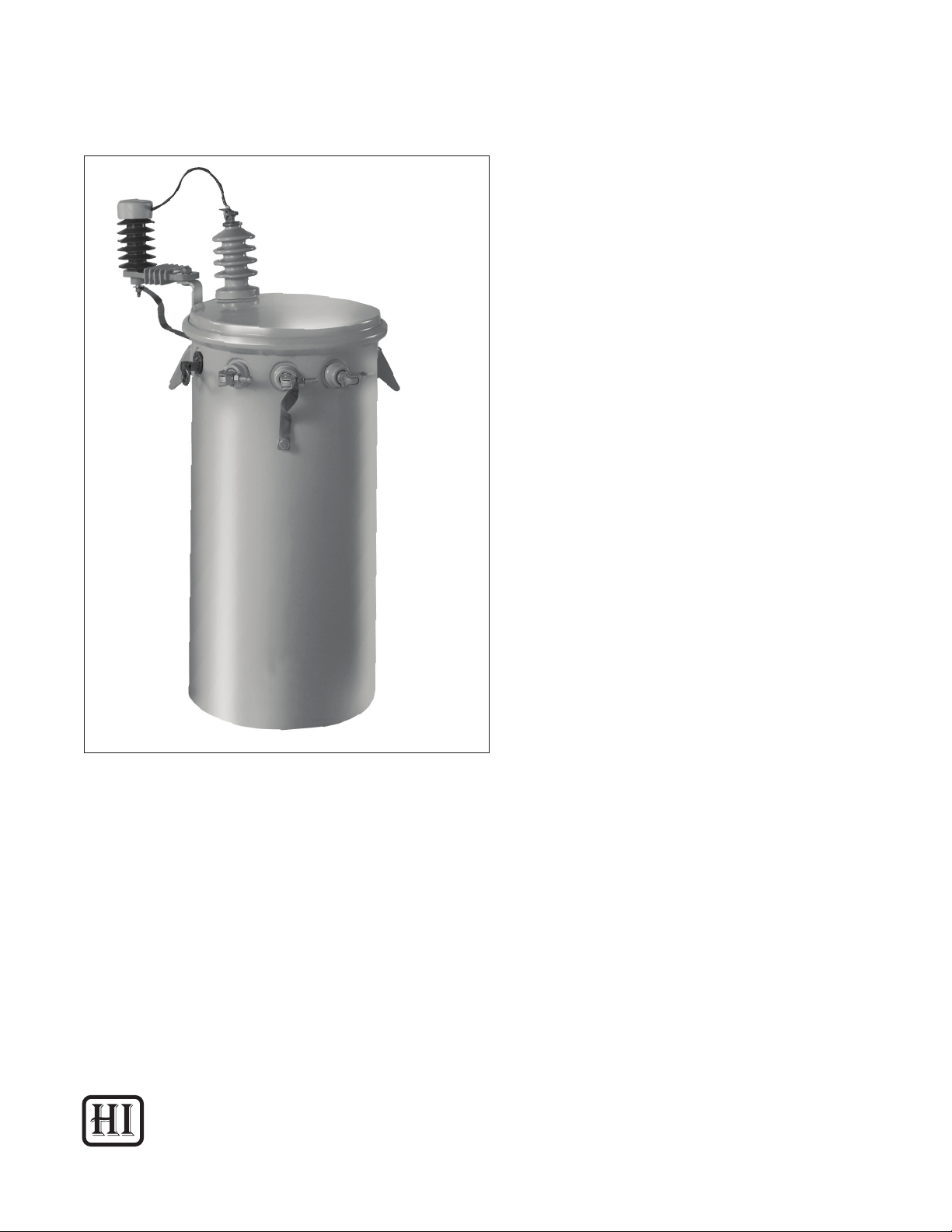
Fluid-Filled Overhead Distribution Transformers
Document 2.4.95, Revision 0
May, 2013
Instructions (HI-102)
Installation, Operation and Maintenance of
Fluid-Filled Overhead Distribution Transformers
Howard Industries
Distribution Transformer Division
1
Page 2

Document 2.4.95, Revision 0
May. 2013
! READ THIS IMPORTANT SAFETY INFORMATION
▲
READ THIS ENTIRE INSTRUCTION MANUAL CAREFULLY AND BECOME FAMILIAR WITH THE EQUIPMENT AND ALL SAFETY-RELATED INFORMATION BEFORE PROCEEDING WITH INSTALLATION, OPERATION, OR MAINTENANCE ACTIVITIES.
Safe use of this equipment is dependent on proper installation, operation, and maintenance procedures. Follow all applicable local and national codes.
Do not attempt to service or perform maintenance activities on the equipment until it has been effectively de-energized, and all high-voltage and low-voltage bushing terminals have been properly
grounded. Do not rely solely on fuse removal or switch position as conclusive indication that a transformer is de-energized. Be absolutely certain that a transformer is de-energized by checking for zero
voltage on all terminals.
Only qualied personnel should install, maintain, and operate this equipment. Qualied personnel
are those who are trained in the installation, maintenance, and operation of high-voltage equipment,
trained in the proper use of personal protective equipment (PPE) and trained in appropriate rst aid
procedures. Refer to NFPA 70E.
Fluid-Filled Overhead Distribution Transformers
Certain information in this manual is marked with the words DANGER, WARNING, or CAUTION, which
indicate hazards as listed below.
DANGER indicates an imminently hazardous situation which, if not avoided, will result in death
or serious personal injury, and could also result in damage to the equipment.
WARNING indicates a potentially hazardous situation which, if not avoided, could result in
death or serious personal injury, and could also result in damage to the equipment.
CAUTION indicates a potentially hazardous situation which, if not avoided, could result in minor
or moderate personal injury, and could also result in damage to the equipment.
These instructions are intended as a general guide for the installation, operation and maintenance of
the equipment, when operated in “Usual Service Conditions” as dened in IEEE Standard C57.12.00.
Although every effort has been made to ensure accuracy and completeness, these instructions do
not address every conceivable application or circumstance that might be encountered. Howard Industries makes no representation or warranty with respect to, and assumes no responsibility for the
completeness, accuracy, sufciency, or usefulness of, these instructions. Features presented herein
may not be present in all equipment designs. Standard and optional features are subject to change
without notice.
Questions regarding installation, operation, and maintenance of the equipment, particularly when
encountering unusual or special circumstances which may not be sufciently covered by these instructions, should be directed to the Howard Industries Transformer Division.
2
Page 3

Document 2.4.95, Revision 0
Fluid-Filled Overhead Distribution Transformers
May, 2013
TABLE OF CONTENTS
IMPORTANT SAFETY INFORMATION ................................................................................................................................2
SECTION 1: INTRODUCTION ..............................................................................................................................................5
SECTION 2: RECEIVING, HANDLING, AND STORAGE .....................................................................................................6
Drawings and Documents ...........................................................................................................................................6
Lifting and Handling ..................................................................................................................................................... 6
Initial Inspection ............................................................................................................................................................ 6
Fluid Level ......................................................................................................................................................................7
Internal Inspection ....................................................................................................................................................... 7
Fluid Sampling ...............................................................................................................................................................7
Transformer Storage ....................................................................................................................................................7
SECTION 3: INSTALLATION ................................................................................................................................................9
Lifting and Handling ..................................................................................................................................................... 9
Location and Mounting ................................................................................................................................................ 9
Grounding ....................................................................................................................................................................10
High-Voltage and Low-Voltage Connections ..............................................................................................................10
Reconguring the Internal Low-Voltage Connections ...............................................................................................10
SECTION 4: INSPECTION AND TESTING .........................................................................................................................11
Pre-Energization Inspection and Tests ......................................................................................................................11
Ratio Test .....................................................................................................................................................................11
Insulation Resistance Test..........................................................................................................................................11
Multiple-Voltage Switch Setting ..................................................................................................................................11
Tap Switch Setting .......................................................................................................................................................11
Grounding ....................................................................................................................................................................12
Bolted Connections. ....................................................................................................................................................12
Fluid Level ....................................................................................................................................................................12
Fluid Temperature .......................................................................................................................................................12
Internal Fault Detector ................................................................................................................................................12
Current Transformers. .................................................................................................................................................12
Accessory Wiring .........................................................................................................................................................12
Tank Finish ..................................................................................................................................................................12
Internal Inspection ......................................................................................................................................................12
Post-Energization Inspection and Tests .....................................................................................................................12
Verifying Correct Voltage .............................................................................................................................................12
Checking for Leaks. .....................................................................................................................................................13
Observing Operation ...................................................................................................................................................13
Checking Gauges ........................................................................................................................................................13
Audible Sound .............................................................................................................................................................13
SECTION 5: OPERATION OF SWITCHING AND PROTECTIVE DEVICES .......................................................................14
Hot-Stick Operable Devices ........................................................................................................................................14
Taps and Multiple-Voltage Windings ..........................................................................................................................14
Tap Switch....................................................................................................................................................................15
Multiple-Voltage Switch ..............................................................................................................................................15
Fuses ...........................................................................................................................................................................15
Internal Weak-Link Fuse .............................................................................................................................................16
Partial-Range Current-Limiting Fuse ..........................................................................................................................16
3
Page 4

Document 2.4.95, Revision 0
May. 2013
Fluid-Filled Overhead Distribution Transformers
Surge Arrester .............................................................................................................................................................16
External Surge Arrester ...............................................................................................................................................16
Internal Surge Arrester................................................................................................................................................16
Low-Voltage Circuit Breaker........................................................................................................................................17
Magnex Interrupter .....................................................................................................................................................17
Other Switching and Fusing Devices ..........................................................................................................................18
SECTION 6: OPERATION OF BUSHINGS, GAUGES AND ACCESSORY DEVICES ........................................................19
Hot-Stick Operable Devices ........................................................................................................................................19
Pressure-Vacuum Gauge ............................................................................................................................................19
Fluid Level Gauge and Sight Plug ..............................................................................................................................19
Fluid Temperature Gauge ..........................................................................................................................................19
Drain Valve and Sampling Device ..............................................................................................................................20
Automatic Pressure Relief Valve ...............................................................................................................................20
Internal Fault Detector ...............................................................................................................................................20
Bushings and Terminals ............................................................................................................................................20
High-Voltage Bushings ...............................................................................................................................................21
Low-Voltage Bushings ................................................................................................................................................21
Other Accessory Devices ............................................................................................................................................21
SECTION 7: MAINTENANCE AND REPAIR ......................................................................................................................22
Periodic Inspection......................................................................................................................................................22
Inspection Checklist ....................................................................................................................................................22
Electrical Tests ............................................................................................................................................................23
Exterior Paint Finish ....................................................................................................................................................23
Fluid Leaks ..................................................................................................................................................................24
Audible Sound Level....................................................................................................................................................24
Low-Voltage Circuit Breaker........................................................................................................................................24
Magnex Interrupter .....................................................................................................................................................25
Other Accessory Devices ............................................................................................................................................25
Insulating Fluid ...........................................................................................................................................................25
Sampling the Fluid .....................................................................................................................................................25
Filtering the Fluid ........................................................................................................................................................25
Removing or Lowering the Fluid .................................................................................................................................25
Filling with Fluid ..........................................................................................................................................................25
Opening the Transformer Tank ..................................................................................................................................26
Torque Guidelines .......................................................................................................................................................26
Additional Maintenance Instructions ........................................................................................................................28
Repair Parts ................................................................................................................................................................28
Warranty Claims .........................................................................................................................................................28
Disposal ......................................................................................................................................................................28
Tables
Table 1: Torque Guidelines for External Cabinet Fasteners .....................................................................................27
Table 2: Torque Guidelines for External Bushing Mounting Hardware ....................................................................27
Table 3: Torque Guidelines for External Bushing Terminal Connections .................................................................27
Table 4: Torque Guidelines for Accessories ...............................................................................................................27
4
Page 5

Fluid-Filled Overhead Distribution Transformers
SECTION 1: INTRODUCTION
This document is intended as a general guide for
the installation, operation and maintenance of
Howard Industries uid-lled, overhead distribution
transformers. Although every effort has been
made to ensure accuracy and completeness, these
instructions do not address every conceivable
application or circumstance that might be
encountered. Features presented herein may not
be present in all transformer designs. Standard
and optional features are subject to change without
notice.
The instructions contained herein are applicable
to transformers operated in usual conditions as
specied in the “Usual Service Conditions” section
of IEEE Standard C57.12.00. Questions regarding
installation, operation, and maintenance (particularly
when encountering unusual or special circumstances
not sufciently covered by these instructions) should
be directed to the Howard Industries Transformer
Division.
Document 2.4.95, Revision 0
May, 2013
IT IS IMPORTANT TO READ AND COMPLY WITH ALL
SAFETY INFORMATION AND WARNINGS DISPLAYED
THROUGHOUT THESE INSTRUCTIONS BEFORE
ATTEMPTING ANY INSTALLATION, OPERATION, OR
MAINTENANCE ACTIVITIES.
5
Page 6

Document 2.4.95, Revision 0
May. 2013
SECTION 2: RECEIVING, HANDLING, AND STORAGE
Fluid-Filled Overhead Distribution Transformers
Drawings and Documents
Locate all shipping papers, packing lists,
specications, and other pertinent information for
use during inspection. Verify that the transformer is
supplied with a nameplate, required warning labels,
and terminal designation markings. Verify that the
terminal designation markings are consistent with
those on the nameplate. The transformer nameplate
provides electrical characteristics, winding
connections, and weights. Check the nameplate for
verication of specication compliance, including
voltage and kVA ratings, percent impedance, and
other design characteristics. The transformer wiring
diagram provides details of any control, fan and
alarm wiring that may have been provided.
Lifting and Handling
Overhead transformers may be lifted by crane or
hoist. Properly palletized transformers may also be
lifted by a forklift truck. Refer to the transformer
nameplate to determine the total weight of the
assembled transformer and make sure that the
lifting equipment, hooks, cables, slings and spreader
bars are adequate to perform a safe lift. Do not use
transformer bushings as handles, otherwise undue
stress may damage the bushing and cause a uid
leak. Be aware that cooling radiators, if present,
are made of relatively thin metal and can be easily
damaged. Special care must be taken when handling
transformers, if the ambient temperature is below
minus 20°C (minus 4°F); otherwise, permanent
damage to the transformer may result.
A forklift truck may also be used to lift overhead
transformers that are securely mounted on a
shipping pallet. Lifting forks must be of sufcient
length to extend completely under the pallet. Do not
attempt to lift an un-palletized transformer with a
forklift truck.
!
▲
WARNING
FAILURE TO FOLLOW THE INSTRUCTIONS
BELOW COULD RESULT IN DEATH OR SERIOUS
PERSONAL INJURY, AND COULD ALSO RESULT
IN DAMAGE TO THE EQUIPMENT.
• Lifting equipment, including forklift trucks,
cranes, hoists, cables, straps, lifting bolts,
hoist rings and spreader bars, must be of
adequate capacity to safely lift the completely
assembled transformer.
• Keep unnecessary personnel clear while
unloading and moving the transformer.
Initial Inspection
Although all transformers are carefully inspected and
tested at the factory, a thorough receiving inspection
should be conducted to detect any damage or loss
that might have occurred during shipment. The
receiving inspection should be completed upon
receipt and before unloading from the truck. Note
any damage or discrepancies on the bill of lading,
le a claim with the carrier, and notify the Howard
Industries Transformer Division prior to unloading the
transformer and before attempting any repair.
Lifting the transformer by crane or hoist is
accomplished using the provided lifting lugs. Do not
lift from any points other than the provided lifting
lugs. Do not use holes in the lifting lugs for lifting.
These holes are for tie-down purposes only and are
not suitable for lifting. A spreader bar should be used
to keep the lifting cables or slings nearly vertical,
enabling a safe lift and reducing the likelihood of
tank deformation or damage to painted surfaces.
Transformers should be lifted in an upright position,
allowing the transformer to tilt no more than 15
degrees from vertical. Lifting cables or straps should
be no more than 20 degrees from vertical.
6
The following checks should be performed:
1. Read the serial number on the transformer
nameplate and make sure it matches
the serial number listed on the shipping
documents. Also, check the transformer
nameplate for kVA rating, high-voltage rating,
low-voltage rating, impedance and other
design characteristics, and make sure they
comply with the specications.
2. Check shipping documents to make sure
the shipment is complete, including all listed
accessories and hardware. Be aware that
Page 7

Fluid-Filled Overhead Distribution Transformers
Document 2.4.95, Revision 0
May, 2013
additional items may arrive on separate
pallets. Claims for shortages or errors
must be noted on the shipping documents
and reported immediately to the Howard
Industries Transformer Division. Failure
to make a timely claim will constitute
unqualied acceptance and a waiver of all
such claims by the purchaser.
3. The tank vacuum/pressure gauge, if
provided, may indicate a positive or negative
reading when the transformer is received,
depending on the relative temperatures of
the uid and ambient air. A rising or falling
reading that varies over time with ambient
temperature indicates that the transformer
tank is sealed effectively. If the vacuum/
pressure gauge shows a constant zero
reading, this indicates the possibility of a
tank leak. If this occurs, the tank should be
checked carefully for leaks as indicated in
the following step.
4. Check the tank for indication of uid leaks,
looking carefully at weld seams, bushings,
gauges, valves and all other tank ttings. If
suspicious indications are found, investigate
thoroughly to determine if a leak does exist
on the transformer. Indications of a leak
can sometimes be residual uid that was
not cleaned completely during the lling
process and not an actual leak. In many
cases a small pinhole tank leak or leak
from a bushing, gauge, valve or other tting
can be easily repaired on site. Refer to
the “Maintenance and Repair” section for
information about the repair of uid leaks.
5. Check for external damage including
dents or scratches on the tank walls and
radiators, if present. Dents and scratches
can often be repaired on site using simple
touch-up procedures. If touch-up painting
is performed, do not remove or obscure
any warning labels, instructional labels or
nameplates.
6. Check for broken, cracked, or damaged
bushings, gauges, valves and other ttings
and accessories.
7. Check for missing or damaged component
parts and for packages that shipped
separately from the transformer.
Fluid Level
The transformer is shipped from the factory with
insulating uid lled to the proper level. Before
energizing the transformer, verify proper uid level
by observing the uid level gauge, if provided. The
uid level gauge pointer should be between the
“High” and “Low” marks. For transformers provided
with a uid sight plug, the uid level can be directly
observed if it is within acceptable range.
When checking the uid level, be aware that it is
normal for the level to vary as a function of uid
temperature. A transformer found to have an
unusually low uid level should be checked for
potential leaks and lled to the proper level with
the same type of liquid as that specied on the
transformer nameplate. Refer to “Filling with Fluid.”
Internal Inspection
An internal inspection of the transformer tank is
rarely necessary and is recommended only when
there are obvious indications that the transformer
has received severe impact damage during transit
or when necessary to perform recommended preenergization tests or inspections. Do not open
the transformer tank without authorization from
the Howard Industries Transformer Division. If the
transformer tank must be opened, refer to “Opening
the Transformer Tank” for instructions.
Fluid Sampling
Sampling and testing of the uid is not required
unless there is indication that moisture or other
contaminants have accidently entered the tank
during transit. If moisture or contaminants in the
uid is suspected, contact the Howard Industries
Transformer Division immediately for instructions.
If uid sampling is required, refer to “Sampling the
Fluid” for instructions.
Transformer Storage
Transformers may be temporarily stored if properly
prepared. It is recommended that transformers
be stored completely assembled. Prior to storage,
transformers should be thoroughly inspected as
described above in the “Initial Inspection” section.
If the transformer is not completely assembled,
separate components and accessories should be
stored in a clean dry area in their original shipping
7
Page 8

Document 2.4.95, Revision 0
May. 2013
containers. Do not store the transformer in a
corrosive environment.
Transformers may be stored in racks designed for
that purpose. Transformers should not be stacked
directly on top of one another, as this may damage
the tank and bushings.
If the transformer is to be stored for an extended
period of time before being placed into service,
it should be stored on a rm level surface. It is
recommended that the transformer be inspected
periodically while it is in extended storage. Ensure
that an effective pressure seal is maintained, and
check for leaks and corrosion. Any damage or
defects should be repaired immediately.
Fluid-Filled Overhead Distribution Transformers
8
Page 9

Fluid-Filled Overhead Distribution Transformers
SECTION 3: INSTALLATION
Lifting and Handling
Overhead transformers may be lifted by crane or
hoist. Properly palletized transformers may also be
lifted by a forklift truck. Refer to the transformer
nameplate to determine the total weight of the
assembled transformer and make sure that the
lifting equipment, hooks, cables, slings and spreader
bars are adequate to perform a safe lift. Do not use
transformer bushings as handles, otherwise undue
stress may damage the bushing and cause a uid
leak. Be aware that cooling radiators, if present,
are made of relatively thin metal and can be easily
damaged. Special care must be taken when handling
transformers, if the ambient temperature is below
minus 20°C (minus 4°F); otherwise, permanent
damage to the transformer may result.
Lifting the transformer by crane or hoist is
accomplished using the provided lifting lugs. Do not
lift from any points other than the provided lifting
lugs. Do not use holes in the lifting lugs for lifting.
These holes are for tie-down purposes only and are
not suitable for lifting. A spreader bar should be used
to keep the lifting cables or slings nearly vertical,
enabling a safe lift and reducing the likelihood of
tank deformation or damage to painted surfaces.
Transformers should be lifted in an upright position,
allowing the transformer to tilt no more than 15
degrees from vertical. Lifting cables or straps should
be no more than 20 degrees from vertical.
A forklift truck may also be used to lift overhead
transformers that are securely mounted on a shipping
pallet. Lifting forks must be of sufcient length to
extend completely under the pallet. Do not attempt to
lift an un-palletized transformer with a forklift truck.
Document 2.4.95, Revision 0
! WARNING
▲
FAILURE TO FOLLOW THE INSTRUCTIONS BELOW
COULD RESULT IN DEATH OR SERIOUS PERSONAL
INJURY AND COULD ALSO RESULT IN DAMAGE TO
THE EQUIPMENT.
• Lifting equipment, including forklift trucks,
cranes, cables, straps, lifting bolts, hoist
rings and spreader bars, must be of
adequate capacity to safely lift the completely
assembled transformer.
• Keep unnecessary personnel clear while
unloading and moving the transformer.
Location and Mounting
Consult local and national codes to ensure that
the installation meets all applicable requirements.
Location of the transformer must permit it to operate
in conditions that meet the requirements specied
in the “Usual Service Conditions” section of IEEE
Standard C57.12.00. Operation not meeting these
service condition requirements will compromise
transformer capacity and reliability, unless the
transformer is designed specically for operation
in conditions other than usual service conditions.
Contact the Howard Industries Transformer Division if
additional information is needed about location and
mounting issues not covered by these instructions
Overhead distribution transformers are not designed
to be tamper resistant and must be installed in
a location that is secure and accessible only by
authorized personnel. Allow adequate electrical
clearance between all live parts and between
live parts and ground points. Ensure that cooling
radiators are free of obstructions.
May, 2013
Hanger brackets are usually provided for direct
pole mounting of the transformer. Pole capacity
must be sufcient to support the weight of the
transformer. The installed transformer should not tilt
in any direction more than three degrees. Greater
tilt may compromise the insulating uid coverage
of live parts within the tank and may prevent
insulating uid from circulating properly through the
cooling radiators, if present. Improper circulation of
insulating uid may cause overheating and could
result in reduced transformer life.
9
Page 10
Document 2.4.95, Revision 0
May. 2013
Fluid-Filled Overhead Distribution Transformers
When specied by the user, base skids are provided
for mounting the transformer on a solid, level
surface, rather than on a pole. The factory may
elect to provide skids for transformers whose weight
exceeds the capability of pole-mounting brackets.
The mounting surface must be rated to support the
weight of the completely assembled transformer.
Refer to the transformer nameplate for the weight of
the transformer.
Grounding
The transformer must be permanently and effectively
grounded according to applicable local and
national codes. Ground the transformer by using
the ground pads or nuts provided on the tank. Do
not use hanger brackets or any other parts of the
transformer for ground connections. A proper lowresistance ground connection is necessary for safe
operation. Connect all available neutrals to the
system neutrals.
! WARNING
▲
Reconguring the Internal Low-Voltage Connections
Unless otherwise specied by the user, overhead
transformers with three low-voltage bushings are
shipped from the factory with the internal lowvoltage winding congured for the E/2E connection
(for instance, 120/240 or 240/480 Volts). If the
transformer must be recongured for operation
at E Volts (for instance, 120 or 240 Volts), the
transformer cover must be removed and the lowvoltage leads reconnected in parallel. Connections
must be tightened appropriately to prevent
overheating and possible failure of the connection.
Make sure the internal low-voltage leads are
insulated and that they do not touch the tank, each
other or any other surface. Refer to “Opening the
Transformer Tank” for instructions.
FAILURE TO FOLLOW THE INSTRUCTIONS
BELOW COULD RESULT IN DEATH OR SERIOUS
PERSONAL INJURY, AND COULD ALSO RESULT
IN DAMAGE TO THE EQUIPMENT.
The transformer must be permanently and
effectively grounded at all times.
High-Voltage and Low-Voltage Connections
The transformer nameplate illustrates the internal
wiring and external identication of each bushing.
The transformer must be connected and operated
as indicated on the nameplate. High-voltage and
low-voltage bushings are provided with terminals
as specied by IEEE standards for overhead
transformers, or as specied by the customer.
Terminals are usually suitable for connection to
either aluminum or copper conductors.
Before making high-voltage and low-voltage line
connections, check to make sure that all mating
connector surfaces are clean and smooth.
Connections must be tightened adequately to
prevent overheating and possible failure of the
connection. Refer to the nominal torque guidelines
contained in Table 3. Avoid excessive cantilever
loads on bushings, otherwise bushing or gasket
damage may result.
10
Page 11

Fluid-Filled Overhead Distribution Transformers
SECTION 4: INSPECTION AND TESTING
Document 2.4.95, Revision 0
May, 2013
Pre-Energization Inspection and Tests
After the transformer has been installed, but before it is energized, the following tests and checks
should be performed at a minimum to ensure that
the transformer is ready to be energized. The transformer should not be energized without successfully
completing these tests and checks.
! DANGER
▲
FAILURE TO FOLLOW THE INSTRUCTIONS
BELOW WILL RESULT IN DEATH OR SERIOUS
PERSONAL INJURY, AND COULD ALSO RESULT
IN DAMAGE TO THE EQUIPMENT.
Be aware of dangerous voltages and avoid
personal contact with live terminals.
! WARNING
▲
FAILURE TO FOLLOW THE INSTRUCTIONS
BELOW COULD RESULT IN DEATH OR SERIOUS
PERSONAL INJURY, AND COULD ALSO RESULT
IN DAMAGE TO THE EQUIPMENT.
• Only qualied personnel with appropriate
equipment should measure transformer
voltages.
• Wear personal protective equipment (PPE)
to prevent injury from potential arc-ash or
contact with dangerous voltages.
• Make sure the transformer is securely and
effectively grounded at all times.
• Current transformer (CT) leads, if present,
must be connected to a metering load or
shorted together and grounded to prevent
dangerous voltages at the CT terminals.
• After successful completion of the
recommended tests and checks, energize the
transformer from a remote location.
1. Ratio Test—Using a transformer turns ratio tester
(TTR), perform a ratio test to verify the primaryto-secondary winding ratio. The measured
value should be within 0.5% of the voltage ratio
indicated on the transformer nameplate. If the
transformer is provided with high-voltage taps
(or low-voltage taps on step-up/step-down transformers having low-voltage ratings above 600
Volts), measure the ratio at each tap position to
ensure that each of the ratios is correct.
When internal low-voltage windings have been
recongured by the user as described above in
“Reconguring the Low-Voltage Internal Connections”, the ratio test will conrm that the
transformer has the correct output voltage and
polarity. Follow the instructions and safety precautions provided by the TTR equipment manufacturer. For additional information about ratio
testing, refer to IEEE Standard C57.12.90.
2. Insulation Resistance Test—Perform a 1,000-
Volt insulation test (Megger test) to measure the
resistance of the insulation between windings
and from each winding to ground. Follow the
instructions and safety precautions provided
by the test equipment manufacturer. Prior to
the test, bushings must be thoroughly cleaned
with denatured alcohol to remove any moisture
or contaminants that could inuence the test
results. Measured resistance should be at least
1.0 GΩ.
3. Multiple-Voltage Switch Setting—On transform-
ers provided with a multiple-voltage switch,
check the switch setting to make sure it is set
to the correct position and that the locking
screw, if provided, is engaged. When specied,
the multiple-voltage switch may be mounted
internally and accessibly only after removing the
transformer cover or, if provided, the handhole
cover. Before removing the cover or handhole
cover, refer to “Opening the Transformer Tank”
for instructions.
4. Tap Switch Setting—On transformers provided
with taps, check the tap switch setting to ensure
it is set to the proper position for the required
voltage, and that the locking screw, if provided,
is engaged. When specied, the tap switch may
be mounted internally and accessible only after
removing the transformer cover or, if provided,
the handhole cover. For transformers provided
with both taps and multiple-voltage windings,
make sure the tap switch is in the position
indicated on the nameplate when the multiple-
11
Page 12

Document 2.4.95, Revision 0
May. 2013
Fluid-Filled Overhead Distribution Transformers
voltage switch is in the parallel position. Before
removing the cover or handhole cover, refer to
“Opening the Transformer Tank” for instructions.
5. Grounding—Check to ensure that the trans-
former tank is securely and effectively grounded.
The transformer tank ground pad or nut is
located on the tank.
6. Bolted Connections—Check all bolted connec-
tions for tightness, referring to nominal torque
guidelines contained in Tables 1 through 4.
7. Fluid Level—Check to make sure the uid level
is correct as indicated by the uid level gauge
or sight plug, if provided. Be aware that uid
temperature and orientation of the transformer
tank will cause the uid level to vary. Transformers are lled to a level that corresponds to a uid
temperature of 25°C. The actual uid level will
increase with increasing temperature. The uid
level indication will also vary when the transformers is not installed in a level orientation.
8. Fluid Temperature—Observe the uid tempera-
ture gauge and make sure the temperature is
no lower than indicated below before the unit is
energized.
-20°C (-4°F) for conventional transformer oil
and silicone uid
0°C (32°F) for R-Temp uid
-10°C (14°F) for FR3™ uid
9. Internal Fault Detector—If the transformer is
provided with an Internal Fault Detector (IFD),
remove the orange shipping lock after the transformer is installed and before it is placed into
service.
10. Current Transformers—If current transform-
ers (CT’s) are present, connect CT leads to the
metering load. If CT leads are not connected to
a metering load, they must be shorted together
and grounded before the transformer is energized.
unless necessary. If the transformer tank must be
accessed, refer to “Opening the Transformer Tank”
for instructions.
Post-Energization Inspection and Tests
After the transformer is energized, the following tests
and inspections should be performed.
! DANGER
▲
FAILURE TO FOLLOW THE INSTRUCTIONS
BELOW WILL RESULT IN DEATH OR SERIOUS
PERSONAL INJURY, AND COULD ALSO RESULT
IN DAMAGE TO THE EQUIPMENT.
Be aware of dangerous voltages within the
terminal compartment and avoid personal
contact with live terminals.
! WARNING
▲
FAILURE TO FOLLOW THE INSTRUCTIONS
BELOW COULD RESULT IN DEATH OR SERIOUS
PERSONAL INJURY, AND COULD ALSO RESULT
IN DAMAGE TO THE EQUIPMENT.
• Energize the transformer from a remote
location.
• Only qualied personnel with appropriate
equipment should measure transformer
voltages.
• Wear personal protective equipment (PPE)
to prevent injury from potential arc-ash or
contact with dangerous voltages.
• Make sure the transformer is securely and
effectively grounded at all times.
• Current transformer (CT) leads must be
connected to a metering load or shorted
together and grounded to prevent dangerous
voltage at the CT terminals.
11. Accessory Wiring—Check wiring of control and
alarm circuits, if provided, to make sure there
are no loose connections and no damage to wire
insulation.
12. Tank Finish—Check all painted surfaces to make
sure that there is no damage or corrosion.
13. Internal Inspection—Transformer tanks are
sealed at the factory and should not be opened
12
1. Verifying Correct Voltage—Before supplying
voltage from the transformer to the load, verify
that the secondary voltages are correct. Using a
suitable AC voltmeter, measure the voltage of the
secondary windings and make sure they agree
with the secondary voltages listed on the transformer nameplate.
Page 13

Fluid-Filled Overhead Distribution Transformers
2. Checking for Leaks—Check the tank to make
sure there are no uid leaks.
3. Observing Operation—After the transformer is
initially energized, visually inspect it to make sure
that no abnormal conditions are observed.
4. Checking Gauges—Observe the uid level and
uid temperature gauges (if provided) to conrm
the proper uid level and temperature.
Document 2.4.95, Revision 0
May, 2013
5. Audible Sound—
It is normal for transformers
to emit an audible humming sound, which is
primarily caused by alternating magnetic ux in
the transformer core. Amplitude and harmonic
content of the sound is inuenced by transformer
size, the energizing voltage level and sinusoidal
purity, load conditions and acoustic conditions
at the installation site. Refer to NEMA Standards
Publication TR1, Transformers, Regulators and
Reactors, and IEEE Standard C57.12.90, IEEE
Standard Test Code for Liquid-Immersed Distribution, Power, and Regulating Transformers, for
more information about design sound levels and
factory sound testing. Unusual sounds should be
investigated, as this might indicate a potential
problem.
13
Page 14

Document 2.4.95, Revision 0
May. 2013
SECTION 5: OPERATION OF SWITCHING AND PROTECTIVE DEVICES
The following operating instructions and descriptions
of switching and fusing devices are intended to be
a general guide for operation of Howard Industries
uid-lled overhead distribution transformers in
normal environments. Although every effort has been
made to ensure accuracy and completeness, these
instructions and descriptions do not address every
conceivable application or circumstance that might
be encountered. Personnel should read and comply
with any safety and instructional labels that accompany an accessory device.
Some of the accessory devices described below are
optional and may not be present in any particular
transformer design. The inclusion of particular accessory devices in any transformer design is governed
by industry standards and by individual customer
specications.
Fluid-Filled Overhead Distribution Transformers
! WARNING
▲
FAILURE TO FOLLOW THE INSTRUCTIONS
BELOW COULD RESULT IN DEATH OR SERIOUS
PERSONAL INJURY, AND COULD ALSO RESULT
IN DAMAGE TO THE EQUIPMENT.
• Use a live-line tool (hot stick or shotgun stick)
to operate devices designed to be operated
by a live-line tool.
• Before servicing the transformer, always
de-energize the transformer from a remote
location and then proceed to ground all
primary and secondary transformer terminals
following industry-accepted safe grounding
practices. Grounding secondary terminals
protects against situations such as a standby
generator energizing transformer from the
secondary circuit.
• Follow industry-accepted safety practices.
Utilize personal protective equipment (PPE)
when working with this equipment.
• Do not operate uid-immersed switching
devices when the insulating uid temperature
is below the following limits:
-20°C (-4°F) for conventional transformer
oil and silicone uid
0°C (32°F) for R-Temp uid
-10°C (14°F) for FR3
Hot-Stick Operable Devices
Some devices such as low-voltage circuit breakers,
tap switches, multiple-voltage switches and automatic pressure relief devices are designed to be operated with a live-line tool (hot stick or shotgun stick).
Do not attempt to operate by hand any device that is
designed to be operated with a live-line tool. Inspect,
test and operate the live-line tool according to the instructions provided by the live-line tool manufacturer.
™
uid
14
Taps and Multiple-Voltage Windings
Transformers with low-voltage ratings of 600 Volts or
less can be provided with either high-voltage taps or
Page 15

Fluid-Filled Overhead Distribution Transformers
multiple high-voltage windings. Although not recommended, these transformers also can be designed
with both high-voltage taps and multiple high-voltage
windings. When both are provided, extreme care
must be taken to ensure that the tap switch setting
is in the position shown on the nameplate when the
multiple-voltage switch is in the parallel position.
Failure to set the tap switch in the correct position
could result in an unsafe condition.
Step-up/step-down transformers (transformers with
a low-voltage rating of more than 600 Volts) can be
provided with high-voltage and/or low-voltage taps,
or with multiple high-voltage and/or low-voltage
windings.
Tap switches and multiple-voltage switches are suitable for de-energized operation only. Never operate a
tap switch or multiple-voltage switch while the transformer is energized. These switches are typically
provided with an external operating handle, but when
specied can be designed for internal operation and
accessed by removing the transformer cover or, if
provided, the handhole cover. Before removing the
transformer cover or handhole cover, refer to “Open-
ing the Transformer Tank” for instructions.
To operate the tap switch or multiple-voltage switch
on a de-energized transformer, rst disengage the
locking screw, if provided, and then rotate the switch
handle to the desired position as indicated on the
switch dial plate or switch body and on the transformer nameplate. After verifying that the switch is
set to the desired position, re-engage the locking
screw, if provided, to prevent accidental operation of
the switch.
Tap Switch
The de-energized tap switch may be used to adjust
the voltage ratio of a transformer. It is intended to
allow adjustment of the output (secondary) voltage
to the rated value. Tap switches usually have ve or
seven tap positions as indicated on the switch dial
plate or switch body and on the transformer nameplate. Do not use the tap switch to raise or lower the
output voltage to any other than the rated voltage
indicated on the transformer nameplate. If the tap
switch is set to provide an output voltage different
from rated secondary voltage, improper transformer
operation will occur.
Document 2.4.95, Revision 0
! WARNING
▲
FAILURE TO FOLLOW THE INSTRUCTIONS
BELOW COULD RESULT IN DEATH OR SERIOUS
PERSONAL INJURY, AND COULD ALSO RESULT
IN DAMAGE TO THE EQUIPMENT.
• Do not operate a de-energized multiple-voltage switch unless the transformer is completely de-energized.
• Do not re-energize the transformer unless
the multiple-voltage switch handle or cap is
secured in the desired position.
The transformer is usually shipped from the factory
with the tap switch set to the rated voltage position,
unless otherwise specied. Always check the tap
switch position to make sure it is set correctly.
Multiple-Voltage Switch
The de-energized multiple-voltage switch is used to
allow operation of the transformer on multiple system voltages. Switch positions and available ratings
are shown on the transformer nameplate. Unless
otherwise specied, transformers with multiplevoltage windings are shipped from the factory with
the multiple-voltage switch set to the highest voltage
position.
! WARNING
▲
FAILURE TO FOLLOW THE INSTRUCTIONS BELOW COULD RESULT IN MINOR OR MODERATE
PERSONAL INJURY, AND COULD ALSO RESULT
IN DAMAGE TO THE EQUIPMENT.
• Do not operate a de-energized multiplevoltage switch unless the transformer is
completely de-energized.
• Do not re-energize the transformer unless
the multiple-voltage switch handle or cap is
secured in the desired position.
Fuses
A blown fuse may indicate a faulted transformer. Do
not replace a blown fuse unless the cause of the
fuse operation has been identied and corrected.
Fuses should be applied according to the fuse rating.
May, 2013
15
Page 16

Document 2.4.95, Revision 0
May. 2013
Fluid-Filled Overhead Distribution Transformers
Replacement fuses should have the proper rating
and operating characteristics. Refer to the circuit
diagram on the transformer nameplate for the location of fuses.
! WARNING
▲
FAILURE TO FOLLOW THE INSTRUCTIONS
BELOW COULD RESULT IN DEATH OR SERIOUS
PERSONAL INJURY, AND COULD ALSO RESULT
IN DAMAGE TO THE EQUIPMENT.
• Do not replace a blown fuse unless the cause
of the fuse operation has been identied and
corrected.
• De-energize the transformer and ground all
terminals before replacing fuses.
• Only qualied personnel with appropriate
measurement devices should measure the
voltages on the transformer.
Internal Weak-Link Fuse
The optional internal weak-link fuse is a uid-immersed expulsion fuse that is designed to isolate the
transformer from the distribution system in the event
of an overload or an internal transformer fault on the
load side of the fuse. The fuse is mounted at the
bottom of the high-voltage bushing or in some cases
on a terminal block located on the multiple-voltage
switch or between the high-voltage bushing and the
high-voltage coil. The presence of a weak-link fuse, if
provided, will be indicated on the transformer nameplate.
Fuses can be accessed by removing the transformer
cover or, if a handhole is provided, by removing the
handhole cover. When accessing the fuse, observe
the precautions and instructions discussed in “Open-
ing the Transformer Tank.”
current-limiting fuse has operated, the transformer
should be considered faulted and removed from service. The presence of a partial-range current limiting
fuse, if provided, will be indicated on the transformer
nameplate.
Surge Arrester
The optional surge arrester is used to protect the
transformer from damage due to over-voltage transients (such as lightning surges), which propagate
through the distribution system. Surge arresters may
be provided as an externally-mounted device or as
an internal uid-immersed device. The surge arrester
should be installed only on systems where the power
frequency voltage at the arrester does not exceed
the arrester’s published maximum continuous operating voltage (MCOV) value.
External Surge Arrester
The external arrester line-lead and tank grounding
connections should be checked to ensure they are
tight before placing the transformer in service. Refer
to Table 3 for torque guidelines.
! WARNING
▲
FAILURE TO FOLLOW THE INSTRUCTIONS
BELOW COULD RESULT IN DEATH OR SERIOUS
PERSONAL INJURY, AND COULD ALSO RESULT
IN DAMAGE TO THE EQUIPMENT.
• De-energize the transformer from a remote
location and make sure all transformer
terminals and bushings have zero voltage
before connecting or servicing surge
arresters.
• Disconnect all surge arresters before
performing impulse, induced-potential or
applied-potential tests.
Partial-Range Current-Limiting Fuse
The optional partial-range current-limiting fuse is
designed to limit the energy released by a low-impedance (high-current) internal fault and reduce the
likelihood of violent transformer failure. A weak-link
expulsion fuse is normally installed in series with the
partial-range current-limiting fuse. The purpose of
the weak-link expulsion fuse is to clear a high-impedance fault or overload. When properly applied, the
partial-range current-limiting fuse will operate only
for internal transformer faults. When a partial-range
16
Disconnect the external surge arrester line-lead
before performing impulse, induced-potential or
applied-potential tests; otherwise, the arrester may
be damaged. Reconnect the surge arrester after
testing and before placing the transformer back into
service.
Internal Surge Arrester
The optional internal metal-oxide-varister (MOV)
Page 17

Fluid-Filled Overhead Distribution Transformers
Document 2.4.95, Revision 0
May, 2013
surge arrester is designed to be uid immersed and
mounted inside the transformer tank. It is recommended that the uid-immersed MOV arrester not
be exposed to an average uid temperature exceeding 90°C (194°F) or a maximum uid temperature
exceeding 125°C (257°F).
Disconnect the uid-immersed MOV surge arrester
before performing impulse, induced-potential or
applied-potential tests; otherwise, the arrester may
be damaged. Reconnect the surge arrester after
testing and before placing the transformer back into
service. Refer to “Opening the Transformer Tank” for
instructions.
Low-Voltage Circuit Breaker
The optional uid-immersed, low-voltage circuit
breaker uses an automatic trip system to help
protect the transformer from damage caused by
overloads and short circuits. The presence of a
low-voltage circuit breaker will be indicated on
the transformer nameplate. The circuit breaker
coordinates with an internal protective link or
internal current-limiting fuse, so that the breaker
operates rst for overloads and faults on the load
side of the transformer.
− To open the circuit breaker, rotate the
handle so that the pointer is at the OPEN
(“O”) position.
− To close the circuit breaker, rotate the
handle, so that the pointer is at the CLOSED
(“C”) position.
− To reset the circuit breaker after it has
tripped, rotate the handle, so that the
pointer is at the RESET (“R”) position. Then
rotate the handle, so that the pointer is at
the CLOSED (“C”) position.
The circuit breaker may be provided with optional
emergency overload capability. The emergency
overload lever is located adjacent to the operating handle. To provide continued service during an
overload situation, rotate the emergency overload
lever to temporarily raise the breaker trip setting.
Rotation of the lever is variable, so that more or less
overload capability can be selected. Overload operation should be minimized to prevent excessive loss of
transformer life. When shipped from the factory, the
emergency overload lever is secured with a meter
seal to prevent accidental operation.
! WARNING
▲
FAILURE TO FOLLOW THE INSTRUCTIONS
BELOW COULD RESULT IN DEATH OR SERIOUS
PERSONAL INJURY, AND COULD ALSO RESULT
IN DAMAGE TO THE EQUIPMENT.
• Do not rely solely on the circuit breaker to deenergize the transformer secondary. Always
ground the secondary terminals before
performing work.
• Even with the circuit breaker in the OPEN
position, there may be sufcient capacitive
coupling to cause a shock hazard at
ungrounded secondary terminals.
• Use a live-line tool (hot stick or shotgun stick)
to operate the low-voltage circuit breaker.
Never operate the breaker by hand.
The circuit breaker operating handle is located on
the side of the transformer tank and is designed to
be operated with a live-line tool (hot stick), as follows.
When specied, the circuit breaker can be provided
with an overload signal light. Illumination of the
signal light indicates that the transformer has been
heavily overloaded. The signal light remains illuminated until the breaker handle is rotated to the
RESET (“R”) position.
The circuit breaker is not intended as a disconnect
device for routine transformer operation. The circuit
breaker does not provide a visible disconnect and
should not be relied on as the sole indication that
the transformer secondary terminals are de-energized.
Magnex Interrupter
The optional Magnex Interrupter is an over-current
protective device and load-break switch, which is
internally mounted under oil and connected into the
high-voltage circuit of the transformer. The interrupter coordinates with an internal protective link
or internal current-limiting fuse, so the interrupter
operates rst for overloads or faults on the load side
of the transformer. The presence of a Magnex Interrupter will be indicated on the transformer nameplate. The following procedures are intended as a
17
Page 18

Document 2.4.95, Revision 0
May. 2013
Fluid-Filled Overhead Distribution Transformers
general guide for operation of the Magnex Interrupter. Personnel should read and follow Cooper Power
Systems Magnex Interrupter Installation Instructions
S240-34-1.
The operating handle is located on the side of the
transformer tank and is designed to be operated
with a live-line tool (hot stick), as follows.
− To open the interrupter, rotate the handle
upward in a counterclockwise direction,
until the spring-loaded contacts open and
the handle is in the OPEN position.
− To close the interrupter, rotate the handle
downward in a clockwise direction, until the
handle is against the physical stop in the
CLOSED position. When in the CLOSED position, the interrupter will operate automatically due to an over-current condition or rise
in oil temperature.
− To reset the interrupter after it has tripped,
rotate the handle upward in a counterclockwise direction to the OPEN position, and
then downward in a clockwise direction,
until the handle is against the physical stop
in the CLOSED position.
An optional trip indicator is available, consisting of
an indicator lens which appears orange when the
interrupter is in the TRIPPED position.
Some Magnex Interrupters are supplied with an
optional emergency overload setting. The emergency
overload will allow approximately 30% overload before tripping. Using a live-line tool (hot stick), operate
the emergency overload as follows.
downward in a clockwise direction, until the
handle is in the CLOSED position.
The Magnex Interrupter does not provide a visible
disconnect and should not be relied on as the sole
indication that the transformer secondary terminals
are de-energized.
! WARNING
▲
FAILURE TO FOLLOW THE INSTRUCTIONS
BELOW COULD RESULT IN DEATH OR SERIOUS
PERSONAL INJURY, AND COULD ALSO RESULT
IN DAMAGE TO THE EQUIPMENT.
• Do not rely solely on the Magnex interrupter
to de-energize the transformer secondary.
Always ground the secondary terminals
before performing work.
• Operate the Magnex Interrupter with a liveline tool (hot stick or shotgun stick). Never
operate by hand.
• Do not operate the Magnex Interrupter if
there is evidence of tank distress or leaking.
• The handle must be rotated fully against the
stop in the CLOSED position.
Other Switching and Protective Devices
Overhead transformers may be provided with
switching and protective devices not discussed
in these instructions. In such cases, contact the
Howard Industries Transformer Division or the device
manufacturer for instructions.
− To enable emergency overload, rotate the handle
upward in a counterclockwise direction, until the
handle is in the OPEN position. Next, turn the
emergency overload lever counterclockwise to
the EO position. Then rotate the handle downward in a clockwise direction, until the handle is
in the CLOSED position.
− To disable emergency overload, rotate the
handle upward in a counterclockwise direction,
until the handle is in the OPEN position. Next,
turn the emergency overload lever clockwise to
the NORMAL position. Then rotate the handle
18
Page 19

Fluid-Filled Overhead Distribution Transformers
SECTION 6: OPERATION OF BUSHINGS, GAUGES AND
Document 2.4.95, Revision 0
May, 2013
ACCESSORY DEVICES
Some of the devices described below are optional
and may not be present in any particular transformer
design. The inclusion of particular accessory devices
in any transformer design is governed by industry
standards and by individual user specications.
Hot-Stick Operable Devices
Some devices such as low-voltage circuit breakers,
switches and automatic pressure relief valves are
designed to be operated with a live-line tool (hot stick
or shotgun stick). Do not attempt to operate by hand
any device that is designed to be operated with a liveline tool. Inspect, test and operate the live-line tool
according to the instructions provided by the live-line
tool manufacturer.
Pressure-Vacuum Gauge
The pressure-vacuum gauge is a dial-type instrument
that indicates the pressure in the tank gas space
relative to atmospheric pressure. The gauge is
mounted on the transformer tank above the uid
level. Pressure in the tank will normally vary as a
function of transformer and ambient temperatures.
If the transformer is lightly loaded or de-energized
during times of low ambient temperature, the gauge
may indicate a negative pressure.
The pressure-vacuum gauge may be provided with
optional switch contacts, which can be used to
provide a remote alarm.
Fluid Level Gauge and Sight Plug
The uid level gauge is a dial-type device that
indicates the uid level inside the transformer tank.
The gauge is mounted on the transformer tank at
the normal 25°C uid level. Transformers may be
provided with a uid sight plug instead of a uid level
gauge to allow direct observation of the uid level.
The top uid level should be visible in the sight plug.
If the gauge or sigh plug indicates a low uid level, the
cause of the low reading should be investigated and
corrected. A low uid level can cause overheating of
the transformer and can compromise the insulation
system. The uid level gauge may be provided with
optional switch contacts, which can be used to
provide a remote alarm of low uid level.
Be aware that uid temperature and orientation of
the transformer tank will cause the uid level to vary.
Transformers are lled to a level that corresponds to
a uid temperature of 25°C. The actual uid level will
increase with increasing temperature. The uid level
indication will also vary when the transformer is not
installed in a level orientation.
Fluid Temperature Gauge
The uid temperature gauge is a dial-type bi-metal
instrument that indicates the uid temperature at
the top of the uid column. The temperature gauge is
mounted on the transformer tank near the top of the
uid column.
! WARNING
▲
FAILURE TO FOLLOW THE INSTRUCTIONS BELOW COULD RESULT IN MINOR OR MODERATE
PERSONAL INJURY, AND COULD ALSO RESULT
IN DAMAGE TO THE EQUIPMENT.
If the pressure-vacuum gauge constantly reads
zero under varying load and ambient conditions,
the transformer should be checked for a possible
tank leak. A leak will allow moisture and air to
enter the transformer tank, which could degrade
the paper insulation and insulating uid. Left
unrepaired, a leak could limit transformer life or
cause a violent failure.
The gauge may be furnished with a red drag-hand
pointer that indicates the maximum temperature
reached since it was last reset. The drag-hand can
be reset by rotating the magnet at the center of the
dial or, on some types, by pressing a reset button.
The uid temperature gauge may also be provided
with switch contacts, which can be used to provide a
remote alarm, or to energize a fan control circuit.
During normal operation the uid temperature
gauge should read less than the sum of the ambient
temperature and the rated temperature rise (normally
a sum of 85°C). Refer to IEEE Standard C57.91,
IEEE Guide for Loading Mineral-Oil-Immersed
Transformers and Step-Voltage Regulators, for loading
recommendations.
19
Page 20

Document 2.4.95, Revision 0
May. 2013
Drain Valve and Sampling Device
The drain valve and sampling device permit draining
the transformer uid and sampling the uid for
testing purposes. The valve is located near the
bottom of the transformer tank. Refer to “Sampling
and Testing the Fluid” and “Draining and Filling the
Tank” for the uid sampling and draining procedures.
Fluid-Filled Overhead Distribution Transformers
! WARNING
▲
FAILURE TO FOLLOW THE INSTRUCTIONS
BELOW COULD RESULT IN DEATH OR SERIOUS
PERSONAL INJURY, AND COULD ALSO RESULT
IN DAMAGE TO THE EQUIPMENT.
Automatic Pressure Relief Valve
The automatic pressure relief valve (PRV) is
designed to relieve excessive tank pressure that
might occur during operation of the transformer.
The valve consists of a self-resealing, spring-loaded
diaphragm. Some PRV types may include a resettable visual ag to indicate that the valve has
operated.
When pressure in the tank exceeds the PRV’s
specied limit, the pressure will cause the valve
to open, venting the excess pressure. After the
internal pressure decreases below the PRV reseal
rating, the valve will automatically close and reseal
the transformer. For PRV’s equipped with a visual
indicating ag, the ag must be manually reset.
! WARNING
▲
FAILURE TO FOLLOW THE INSTRUCTIONS BELOW COULD RESULT IN MINOR OR MODERATE
PERSONAL INJURY, AND COULD ALSO RESULT
IN DAMAGE TO THE EQUIPMENT.
The cause of PRV activation should always be
investigated, since pressure venting may indicate
a potential problem inside the transformer.
• Do not re-energize a transformer if the IFD
has operated.
• Do not attempt to reset the orange signal
ag.
• Always assume that a transformer might be
faulted, even if the IFD has not operated.
• Never rely solely on the IFD as an indicator of
transformer condition.
• The IFD is a visual indicator only, and should
not be relied on as an electrical disconnect
device.
The IFD also includes a standard pressure relief
valve that is integrated into the sensor to relieve
excessive tank pressures that might occur during
normal operation of the transformer. Refer to
information elsewhere in these instructions
regarding operation of an automatic pressure relief
valve.
The IFD incorporates a removable shipping lock
for use during transportation and storage. The
shipping lock must be removed after the transformer
is installed. Re-install the shipping lock if the
transformer must be relocated. Always transport
IFD-equipped transformers with the shipping lock
installed to prevent accidental operation.
Internal Fault Detector
The Internal Fault Detector (IFD) is a mechanical
sensor that activates when sudden pressure from an
internal arcing fault occurs inside the transformer.
If an internal fault occurs, the IFD releases a visible,
non-resettable orange signal ag. This signal ag
alerts crews that the transformer is faulted and
should not be re-energized. Be aware that the IFD
provides only a visual indication that a fault has
occurred. It is not an electrical disconnect device.
20
Bushings and Terminals
Tin-plated eye-bolt or spade terminals are provided
as specied by IEEE standards and are suitable for
connection to either aluminum or copper conductors.
High-voltage and low-voltage connections should be
made as indicated on the transformer nameplate.
Clean and properly tighten all terminal connections
to ensure a low-resistance connection and prevent
overheating. Refer to torque guidelines contained
in Table 3. Ensure that there is sufcient electrical
clearance between all live parts, including both
phase-to-phase and phase-to-ground clearances.
Page 21

Fluid-Filled Overhead Distribution Transformers
Line connections should be made without placing
excessive cantilever load on the bushings. Excessive
loading may cause bushing or gasket damage.
! WARNING
▲
FAILURE TO FOLLOW THE INSTRUCTIONS BELOW COULD RESULT IN MINOR OR MODERATE
PERSONAL INJURY, AND COULD ALSO RESULT
IN DAMAGE TO THE EQUIPMENT.
Do not place excessive cantilever load on a lowvoltage or high-voltage bushing.
High-Voltage Bushings
Internally-clamped cover-mounted porcelain
bushings are typically supplied for connection to the
high-voltage source. Insulated terminal caps may be
provided as an option to prevent wildlife from making
contact with live high-voltage terminals.
Document 2.4.95, Revision 0
May, 2013
Low-Voltage Bushings
Internally-clamped, sidewall-mounted bushings are
typically supplied for connection to the secondary
load. These may be constructed of either molded
plastic or porcelain.
Other Accessory Devices
Transformers may be provided with other accessory
devices not discussed in these instructions. In such
cases, contact the Howard Industries Transformer
Division or the device manufacturer for information.
21
Page 22

Document 2.4.95, Revision 0
May. 2013
Fluid-Filled Overhead Distribution Transformers
SECTION 7: MAINTENANCE AND REPAIR
These instructions are intended as a general guide
for the maintenance and repair of Howard Industries
uid-lled overhead distribution transformers,
when used in typical applications and operated in
normal environments. Although every effort has
been made to ensure accuracy and completeness,
these instructions do not address every conceivable
application or circumstance that might be
encountered.
Transformers should be inspected periodically while
in service, with the frequency determined by service
conditions. Transformers operating in unusual service
conditions should be inspected more frequently. Refer
to IEEE Standard C57.12.00 for a discussion of usual
and unusual service conditions.
Accessories such as pressure relief valves,
temperature gauges, uid level gauges, pressurevacuum gauges and drain valves typically require
no maintenance, except replacement in the event
of damage. Gauges, if present, should be checked
periodically to make sure they are operating properly.
! WARNING
▲
FAILURE TO FOLLOW THE INSTRUCTIONS
BELOW COULD RESULT IN DEATH OR SERIOUS
PERSONAL INJURY, AND COULD ALSO RESULT
IN DAMAGE TO THE EQUIPMENT.
• De-energize transformer from a remote
location before performing any inspection or
maintenance work.
Inspection Checklist
While observing the safety instructions above,
perform the following checks.
1. Inspect for dents or other damage to metal
surfaces and make necessary repairs.
2. Inspect the paint nish for damage, corrosion
or weathering that exposes the primer coat or
bare metal. Repair any paint damage that might
be found. Refer to “Exterior Paint Finish” for
instructions.
3. Inspect thoroughly for evidence of uid leaks,
including tank, radiators, bushings, gauges,
switches, valves and all other accessories and
ttings. Check the uid level and add uid as
necessary to ensure that the proper uid level
is maintained. Refer to “Filling with Fluid.” Fluid
leaks must be repaired immediately to prevent
serious damage to the transformer and danger to
life. Refer to “Fluid Leaks” for instructions.
4. Visually check all gaskets for cracking or other
signs of deterioration, and replace as necessary.
When replacing a gasket, carefully clean mating
surfaces to remove any rust, dirt, transformer
uid, old gasket material, or other contamination
that might prevent a good seal. Use an
appropriate gasket cement when installing new
gaskets. Do not reuse old gaskets.
5. Maintain a clean and unobstructed area around
the transformer, including sufcient clearance
around radiator panels, if present, to ensure
adequate cooling of the transformer.
• Make sure all transformer terminals and
bushings have zero voltage.
• Make sure that the transformer is properly
grounded.
• Fluid leaks should be repaired as soon as
they are discovered.
Periodic Inspection
All exterior surfaces and the transformer
surroundings should be inspected periodically.
Inspection frequency should be governed by
operating conditions at the installation site. More
severe conditions indicate the need for more
frequent inspection.
22
6. Check bushings, valves, gauges, switches and
all other accessories for proper operation, and
repair or replace any defective devices.
7. Check all fasteners for signs of corrosion and
replace as necessary.
8. Check the uid temperature gauge, if present,
including the maximum temperature drag hand,
if provided, to determine whether the uid
temperature has exceeded the design limit.
Any such indication should be investigated to
determine and correct the cause. Reset the drag
hand.
9. Check to make sure the uid level is correct as
indicated by the uid level gauge or sight plug,
Page 23

Fluid-Filled Overhead Distribution Transformers
if provided. Be aware that uid temperature and
orientation of the transformer tank will cause
the uid level to vary. Transformers are lled to
a level that corresponds to a uid temperature
of 25°C. The actual uid level will increase with
increasing temperature. The uid level indication
will also vary when the transformer is not
installed in a level orientation. If the uid level is
low, add uid according to the instructions in the
“Filling with Fluid” section.
10. Check the torque values on all electrical
connections, including ground connections,
and tighten as necessary. Refer to the torque
guidelines contained in Tables 1 through 4.
11. Replace any damaged or unreadable
nameplates, instructional labels, and safety
labels.
12. If it is suspected that water or other
contaminants may have entered the tank, the
uid should be tested to determine its condition.
For transformers lled with conventional
transformer oil, Refer to IEEE Standard C57.106,
"Guide for Acceptance and Maintenance of
"Insulating Oil in Equipment." For transformers
lled with less-ammable high molecular
weight hydrocarbon insulating uid (such as
R-Temp), refer to IEEE Standard C57.212,
"Guide for Acceptance and Maintenance
of Less Flammable Hydrocarbon Fluids in
Transformers." For transformers lled with seed-
based uids (such as Envirotemp FR3
IEEE Standard C57.147, "Guide for Acceptance
and Maintenance of Natural Ester Fluids in
Transformers" for information. For transformers
lled with silicone uid, contact the Howard
Industries Transformer Division for information.
™
) refer to
Document 2.4.95, Revision 0
! DANGER
▲
FAILURE TO FOLLOW THE INSTRUCTIONS
BELOW WILL RESULT IN DEATH OR SERIOUS
PERSONAL INJURY, AND COULD ALSO RESULT
IN DAMAGE TO THE EQUIPMENT.
Be aware of dangerous voltages and avoid
personal contact with live terminals.
! WARNING
▲
FAILURE TO FOLLOW THE INSTRUCTIONS
BELOW COULD RESULT IN DEATH OR SERIOUS
PERSONAL INJURY, AND COULD ALSO RESULT
IN DAMAGE TO THE EQUIPMENT.
• De-energize the transformer and ground all
transformer terminals.
• Only qualied personnel with appropriate
equipment should perform these tests.
• Wear personal protective equipment (PPE)
to prevent injury from potential arc ash or
contact with dangerous voltages.
• Make sure the transformer tank is properly
grounded at all times.
• After testing is complete and the transformer
has been reconnected to the line leads,
energize the transformer from a remote
location.
1. Insulation Resistance Test—Refer to “Insulation
Resistance Test” for instructions.
2. Ratio Test—Refer to “Ratio Test” for instructions.
May, 2013
Electrical Tests
The following electrical tests can be used to
determine the condition of the transformer. Comply
with instructions and precautions provided by
the test equipment manufacturer. Contact the
Howard Industries Transformer Division for further
information.
3. Insulation Power Factor Test—Refer to “Insulation
Power Factor Test” for instructions.
4. Fluid Quality Tests—Moisture content, power
factor, dielectric strength and dissolved gas
analysis.
Exterior Paint Finish
Any damage to the exterior paint nish that exposes
the primer coat or bare metal should be repaired
immediately in order to prevent corrosion. Areas
to be repaired should be thoroughly clean and dry.
The surface should be sanded to remove rust, loose
23
Page 24

Document 2.4.95, Revision 0
May. 2013
Fluid-Filled Overhead Distribution Transformers
paint akes and other debris. The surface should
then be cleaned with a suitable solvent to remove
any oil, grease or other contaminants. At least two
coats of a high-quality touch-up paint should be
applied to the damaged area. Bare metal should
receive a primer coat before applying the nal
nish. Touch-up paint is available from the Howard
Industries Transformer Division.
Fluid Leaks
Check the tank for indication of uid leaks, looking
carefully at weld seams, bushings and all tank
ttings. Fluid leaks should be repaired as soon as
possible to prevent moisture contamination of the
insulating uid and to prevent internal ashover due
to low uid level.
! WARNING
▲
FAILURE TO FOLLOW THE INSTRUCTIONS
BELOW COULD RESULT IN DEATH OR SERIOUS
PERSONAL INJURY, AND COULD ALSO RESULT
IN DAMAGE TO THE EQUIPMENT.
• De-energize transformer from a remote
location before performing any inspection or
maintenance work.
• Make sure all transformer terminals and
bushings have zero voltage.
• Make sure that the transformer is properly
grounded.
• Fluid leaks should be repaired as soon as
they are discovered.
To verify that a uid leak does exist, clean the
suspected leak area with an appropriate solvent
to completely remove the uid and observe the
area for reappearance of uid. To accelerate the
test, pressurize the tank with dry air or dry nitrogen
through the PRV tting to a pressure of 3-4 PSIG. Let
the tank stand under pressure for one to two hours,
then inspect for leaks. Leaks above the uid level
can be detected by applying soap solution prior to
the pressure test.
In many cases a small pin-hole tank leak or leak
from a bushing, gauge, valve or other tting can be
repaired on site. Pin-hole and weld seam leaks can
usually be repaired by welding on a de-energized
transformer. Welding on radiator panels is not
recommended due to the thinner gauge material
used. Very small pin-hole leaks can sometimes be
repaired using an epoxy patch kit designed to repair
oil leaks.
Bushing leaks can sometimes be corrected by
tightening the bushing clamp bolts. Do not exceed
the recommended torque values listed in Table 2 to
prevent the possibility of bushing or gasket damage.
Audible Sound Level
It is normal for transformers to emit an audible
humming sound, which is primarily caused by
alternating magnetic ux in the transformer core.
Amplitude and harmonic content of the sound is
inuenced by transformer size, the energizing voltage
level and sinusoidal purity, load conditions and
acoustic conditions at the installation site. Unusual
sounds should be investigated, as this might indicate
a potential problem.
If a uid leak is suspected, investigate thoroughly
to determine if an actual leak does exist on the
transformer. False indications of a leak can occur
as a result of residual uid that was not sufciently
cleaned after the transformer was lled with uid.
In addition to the presence of uid residue, a low
reading on the uid level gauge, if present, and a
constant zero reading on the pressure/vacuum
gauge, if present, (which does not vary over time
as a function of transformer loading and ambient
temperature) are also indications of a possible uid
leak.
24
Refer to NEMA Standards Publication TR1,
Transformers, Regulators and Reactors, and IEEE
Standard C57.12.90, IEEE Standard Test Code for
Liquid-Immersed Distribution, Power, and Regulating
Transformers for more information about design
sound levels and factory sound testing.
Low-Voltage Circuit Breaker
The low-voltage circuit breaker, if present, is
accessible by removing the transformer cover or
handhole cover. The link to the operating handle
can be adjusted if necessary for proper operation.
Defective breakers should be replaced. Refer to
“Opening the Transformer Tank” for instructions.
Page 25

Fluid-Filled Overhead Distribution Transformers
Document 2.4.95, Revision 0
May, 2013
Magnex™ Interrupter
The Magnex
™
interrupter and protective link, if
present, are accessible by removing the transformer
cover or handhole cover. Interrupters do not normally
require eld adjustment. Defective interrupters
should be replaced. Refer to “Opening the
Transformer Tank” for instructions.
Other Accessory Devices
Other accessory devices, such as a gauges and
valves, typically require no maintenance except for
replacement in the event of malfunction or damage.
Insulating Fluid
For transformers lled with mineral oil, refer to
IEEE Standard C57.106 Guide for Acceptance and
Maintenance of Insulating Oil in Equipment for
additional guidelines that should be observed when
testing or handling insulating uid. For transformers
lled with natural ester uids (such as Envirotemp
™
), refer to IEEE Standard C57.147 Guide for
FR3
Acceptance and Maintenance of Natural Ester Fluids
in Transformers for information. For transformers
lled with silicone uid, contact the Howard Industries
Transformer Division for information.
Removing or Lowering the Fluid
Should it be necessary to remove or lower the
insulating uid, the following procedure should be
used. Use clean pumps and hoses that have not
been contaminated by different types of uids.
Hoses must be designed for handling the particular
uid in the transformer (As an example, rubber hoses
should not be used with mineral oil.).
1. De-energize the transformer, and make sure the
tank and all terminals are effectively grounded.
2. Remove the cover or handhole cover, if provided,
as outlined in the “Opening the Transformer
Tank” section.
3. Use a clean, dry temporary storage container to
contain the uid.
4. Place the pump discharge hose nozzle at the
bottom of storage container.
5. Pump slowly, and do not allow the uid to splash
into the container, as this could introduce air and
moisture into the uid.
6. Do not lower the insulating uid below the top
of the core/coil clamp pan. Exposing coils could
allow moisture to contaminate coil insulation.
Sampling the Fluid
Before sampling the insulating uid, de-energize
the transformer and make sure all bushings and
terminals are effectively grounded. Samples should
be drawn from the bottom of the tank. Refer to
ASTM D923, Standard Practices for Sampling
Electrical Insulating Liquids for recommended
sampling procedures. Also, refer to the sampling
recommendations provided by the manufacturer of
the uid test equipment.
Filtering the Fluid
The insulating uid can be ltered using a lter
press system. A lter press can remove particle
contaminants as well as small amounts of moisture.
Follow the operating instructions provided by the lter
press system manufacturer. Continue to lter the uid
until the dielectric test result is 26kV or greater.
When ltering any particular type of insulating uid,
make sure the lter press system is not contaminated
with any other type of uid. Contamination of the uid
may alter its chemical or physical characteristics and
could reduce its re point.
Filling with Fluid
When relling the transformer with insulating
uid, ll with the same type of uid, following the
procedure outlined below. Do not mix different types
of uids. Care should be taken to avoid introduction
of air bubbles during the lling process. After relling
is complete, allow 24 hours for dissipation of air
bubbles before energizing the transformer. Trapped
air bubbles can reduce the insulation value of the
uid and cause an internal ash-over.
1. Every storage container of transformer uid used
in the lling process should be visually inspected
and tested for water and other possible
contaminants before proceeding with the lling
process.
2. Pump from the bottom of storage container. To
prevent bubbles in the uid, do not allow air to
enter the pump intake.
3. Place discharge hose at the bottom of the
transformer tank to prevent aeration and the
introduction of bubbles.
4. Pump and ll the transformer tank slowly.
25
Page 26

Document 2.4.95, Revision 0
May. 2013
Fluid-Filled Overhead Distribution Transformers
Fill with uid to ll line marked inside the
transformer tank.
Opening the Transformer Tank
Transformer tanks are shipped sealed and should
not be opened unless necessary. If it is necessary
to open the tank, follow the instructions below and
observe all safety warnings. Before removing the
transformer cover or handhole cover, de-energize
the transformer and relieve internal pressure by
operating the pressure relief valve, taking care to
avoid any hot uid that could be expelled from the
PRV.
! WARNING
▲
FAILURE TO FOLLOW THE INSTRUCTIONS
BELOW COULD RESULT IN DEATH OR SERIOUS
PERSONAL INJURY, AND COULD ALSO RESULT
IN DAMAGE TO THE EQUIPMENT.
• Before servicing the transformer, always
de-energize the transformer and then
proceed to ground all primary and secondary
transformer terminals following industryaccepted safe grounding practices.
Grounding secondary terminals protects
against situations such as a standby
generator energizing transformer from the
secondary circuit.
• Release internal pressure by operating the
PRV with a live-line tool before opening the
tank. Be careful to avoid any hot oil that
might be expelled from the PRV.
To prevent contamination of the transformer, do
not open the transformer tank in an unprotected
area during inclement weather or where the air may
contain dirt or other particles. Any of these situations
could contaminate the insulating uid and cause
a transformer failure. The tank opening should be
protected against entry of foreign matter. If it is
necessary to remove some uid from the tank to
allow for inspection or other work, the transformer
must be re-lled with uid after work is completed.
Refer to the instructions In “Removing or Lowering
the Fluid” and “Filling with Fluid.” The transformer
tank should not remain open for more than two
hours. If work is interrupted, the tank should be
resealed, evacuated, and lled with dry air or
nitrogen.
Personnel should not be permitted on top of or
inside the transformer while it is open, unless they
have emptied all pockets and checked for loose
objects that might fall into the tank. All tools should
be accounted for after work is completed. It is
recommended that any tools used on top of the
transformer or inside the tank be attached with
safety cords to prevent them from being lost inside
the transformer.
Personnel must not stand directly on any electrical
insulation. Clean drop cloths should be used under
working areas in the transformer to prevent objects
from dropping into the core/coil assembly.
The following procedure should be used to re-install
the handhole cover.
1. Place the cover gasket in its original position. If
the gasket is damaged, it should be replaced.
2. Re-install the handhole cover. Re-install and
tighten the cover bolt according to the torque
recommendations in Table 1.
3. To ensure a proper cover seal, pressurize the
headspace to 3-4 PSIG and check for leaks.
Torque Guidelines
Tables 1 through 4 below contain recommended
torque values for tightening various connections
on the transformer. Connections with gaskets will
normally relax after initial tightening. Nominal torque
values listed below include an allowance for gasket
relaxation.
Do not over-tighten any connection; otherwise,
gaskets could split due to over-compression, and
components might break. Fluid leaks could result if
tank-mounted components are over tightened. Check
with the Howard Industries Transformer Division
for recommended torque values for any devices or
connections not listed below. Use the manufacturer’s
recommended torque values for any user-provided
devices.
26
Page 27

Fluid-Filled Overhead Distribution Transformers
Document 2.4.95, Revision 0
May, 2013
Table 1: Torque Guidelines for External Fasteners
Fastener Type
Nominal Torque
(in-lbs)
Torque Range
(in-lbs)
3/8” bolt 240 220-260
Hand-hole cover
bolt
Fastener Type
Cover band bolt
Surge arrester
mounting bolts
144 129-158
180 170-185
420 372-368
Table 2: Torque Guidelines for External Bushing
Mounting Hardware
Bushing Type
Nominal
Torque
(in-lbs)
Torque
Range
Low-voltage bushing, molded
Tri-Clamp (without clamp
60 40-80
ring), 3/8” mounting studs
Low-voltage bushing, molded
(with clamp ring), 3/8”
120 90-150
mounting studs
Low-voltage bushing, porce-
lain (with clamp ring), 1/2”
80 70-90
mounting studs
High-voltage bushing, mold-
ed Tri-Clamp (without clamp
60 40-80
ring), 3/8” mounting studs
High-voltage bushing,
molded (with clamp ring),
120 90-150
3/8” mounting studs
High-voltage bushing, porce-
lain
When checking tightness of gasketed components, the measured torque
will normally be less than the nominal torque listed in the table above due to
relaxation of the gasket material. Additional tightening of bushing mounting
hardware may cause the component to crack or the gasket to become over-
compressed.
80 70-90
Table 3: Torque Guidelines for External Terminal
Connections
Nominal
Terminal Type
High-voltage porcelain bushing eye-bolt
High-voltage porcelain bushing end cap
Low-voltage bushing, 5/8”
jam nut
Low-voltage bushing, 1” jam
nut
Low-voltage bushing, 1-1/4”
jam nut
External surge arrester line
lead
External surge arrester
ground lead
When checking tightness of gasketed components, the measured torque
will normally be less than the nominal torque listed in the table above due to
relaxation of the gasket material. Additional tightening of bushing mounting
hardware may cause the component to crack or the gasket to become overcompressed.
Torque
(in-lbs)
210 180-240
168 156-180
600 480-720
600 480-720
720 600-840
180 162-198
180 162-198
Torque
Range
Table 4: Torque Guidelines for Accessories
Component
Bushing-mounted weaklink fuse mounting bolts
Nominal
Torque
(in-lbs)
85 80-90
Torque
Range
(in-lbs)
Fluid-level sight plug 960 900-1020
Fill plug 960 900-1020
Drain plug 960 900-1020
Drain valve 600 480-720
Automatic pressure relief
device, 1/4” NPT
Automatic pressure relief
device, 1/2” NPT
Neutral strap fastener (at
ground pad)
Series/multiple, delta/wye
or tap switch mounting nut
180 160-200
360 324-396
160 140-180
120 96-144
Ground connector 160 140-180
When checking tightness of gasketed components, the measured torque
will normally be less than the nominal torque listed in the table above due to
relaxation of the gasket material. Additional tightening of bushing mounting
hardware may cause the component to crack or the gasket to become overcompressed.
27
Page 28

Document 2.4.95, Revision 0
May. 2013
Additional Maintenance Instructions
Features and accessory devices discussed herein
may not be present in all transformer designs. Some
features or accessory devices may be present on a
transformer, but not discussed in these instructions.
Howard Industries does not represent that these
instructions are complete, sufcient, accurate or
useful in all circumstances.
Questions regarding installation, operation, and
maintenance (particularly when encountering
unusual or special circumstances not sufciently
covered by these instructions) should be directed to
the Howard Industries Transformer Division.
Repair Parts
Repair parts can be ordered from the Howard
Industries Transformer Division. A description of
the part and the transformer serial number will be
required to ensure that the correct part has been
ordered.
Fluid-Filled Overhead Distribution Transformers
Warranty Claims
The Howard Industries Transformer Division
should be notied immediately when problems are
discovered during the warranty period. All warranty
repairs must be made or approved by the Howard
Industries Transformer Division.
Disposal
When disposing of a transformer or transformer
insulting uid, comply with all local, state and federal
regulations regarding the disposal of uid-lled
electrical equipment.
28
Page 29

Fluid-Filled Overhead Distribution Transformers
Document 2.4.95, Revision 0
May, 2013
NOTES
29
Page 30

Document 2.4.95, Revision 0
May. 2013
Fluid-Filled Overhead Distribution Transformers
NOTES
30
Page 31

Fluid-Filled Overhead Distribution Transformers
Document 2.4.95, Revision 0
May, 2013
NOTES
31
Page 32

Document 2.4.95, Revision 0
May. 2013
Fluid-Filled Overhead Distribution Transformers
32
HI-102
Instructions for the Installation, Operation, and Maintenance of
Fluid-Filled Overhead Distribution Transformers
Document 2.4.95, Revision 0 (September 2012)
Copyright © 2012, Howard Industries, Inc. Laurel, Mississippi
Telephone: 601-425-3151
Fax: 601-649-8090
www.howardtransformers.com
 Loading...