

Page 1

INSTALLATION INSTRUCTIONS
For models:
DTDU-35LED-41-MV
This model number does not include a mounting arm, photoelectric control.
Warning
Please read instructions carefully before
attempting to install fixture and retain instructions
for future reference.
Caution: To avoid electrical shock hazard.
• Turn off the electricity before installing or
servicing this fixture.
• Electrical connections need to comply with
National Electric Code and Local Electric Code.
• The fixture should be installed by a qualified
electrician.
General Safety Information
1. Disconnect power during installation and
before servicing.
2. Risk of Fire: Product is for outdoor installation
and use only.
3. To avoid the risk of fire or shock, this fixture
must be wired in accordance with the National
Electric Code and applicable local codes or
ordinances.
4. All work should be performed by a qualified
electrician.
5. To ensure personal safety, proper grounding is
required.
6. Do not touch the yellow portion of the LED
when removing the acrylic refractor. Damage
may occur.
DTDU
LED Dusk-to-Dawn
Utility-grade
WALL MOUNTING
Note: Assure that fixture is mounted to a structurally
sound surface that will support the fixture.
1. Select a location on a structurally secure wall or
pole, minimum 4 feet from the ground.
2. Place mounting section of fixture onto desired
mounting surface, mark and drill holes for
mounting.
3. This fixture can be mounted with three lag screws
which are provided. (Fig. 1, #14).
4. Install the two bottom lag screws first.
5. Place the fixture on the two bottom lag screws and
install the top lag screw.
6. Tighten the top lag screw first and then tighten the
remaining lag screws.
FIXTURE WIRING/INSTALLATION
Note: Connect fixture to supply wires, make sure power
is off.
1. Press stainless steel springs (Fig. 1, #22) outward to
release cover plate (Fig. 1, #24).
2. Feed supply wires through arm and make wiring
connections in the fixture.
3. Connect the incoming power lead wires to terminal
block (Fig. 1, #13) black to black and white to white.
Route lead wires through mounting arm, form a drip
loop, and connect lead wires to power source.
4. Ensure that the power supply voltage and luminaire
voltage ratings match.
5. The fixture must be grounded. Attach ground lead to
ground lug on terminal block (Fig. 1, #13).
6. For wall mount applications, secure the wall mount
cover plate (Fig. 1, #20) by removing the fitter clamp
(Fig. 1, #21), inserting wall mount cover plate (Fig.
1, #20), inverting the fitter clamp (Fig. 1, #21), and
securing with two washers (Fig. 1, #36) and two
screws (Fig. 1, #10).
7. Install shorting cap (Fig. 1, #1) or photoelectric
control by inserting plug into receptacle and twist
until locking in position. Ensure Photocontrol is rated
for the same voltage as the luminaire.
Rev. 5/6/2014
1
Page 2
INSTALLATION INSTRUCTIONS
For models:
DTDU-35LED-41-MV
This model number does not include a mounting arm, photoelectric control.
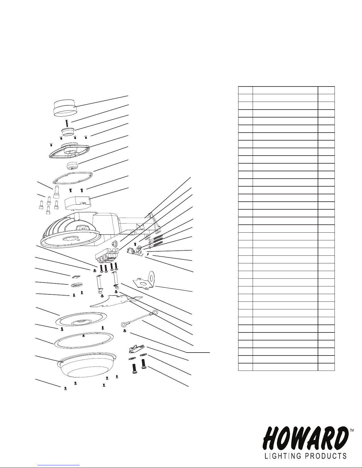
Technical Specifications
Figure 1
1
2
3
4
5
6
7
8
35
9
34
33
32
31
30
29
28
8
27
26
4
21
11
12
13
29
14
15
16
17
18
19
20
22
23
24
25
36
23
DTDU
LED Dusk-to-Dawn
Utility-grade
NO. DESCRIPTION QTY
1
Shorting cap 1
2
Ball screws 1
3
Photocell socket (Top) 1
4
Screws 9
5
Top Cover 1
6
Photocell socket (Bottom) 1
7
Gasket 1
8
Screws 5
9
Driver 1
10 Screws 2
11 Housing 1
12 Water gasket 1
13 Terminal block 1
14 Lag screw 3
15 Heat shrink sleeve 1
16 MOV 3
17 Thermal fuse 1
18 Cable 3
19 PCB 1
20 Wall mount cover plate 1
21 Fitter clamp 1
22 Stainless spring 2
23 Screw with washer 3
24 Cover plate 1
25 Tether cord 1
26 Acrylic refractor 1
27 Gasket 1
28 Refractor 1
29 Ball screws 3
30 LED cover 1
31 LED 1
32 Screw 1
33 Screw 4
34 C4 terminal 4
35 C5 terminal 1
36 Washer 2
Input voltage: 120-277v 50/60Hz
Color Temperature: 4100K
Shorting Cap Included
Consult Factory for Photoelectric Control ordering and specified voltage.
Rev. 5/6/2014
2
Page 3

INSTALLATION INSTRUCTIONS
For models:
DTDU-48-LED-41-MV
This model number does not include a mounting arm, photoelectric control.
Warning
Please read instructions carefully before
attempting to install fixture and retain instructions
for future reference.
Caution: To avoid electrical shock hazard.
• Turn off the electricity before installing or
servicing this fixture.
• Electrical connections need to comply with
National Electric Code and Local Electric Code.
• The fixture should be installed by a qualified
electrician.
General Safety Information
1. Disconnect power during installation and
before servicing.
2. Risk of Fire: Product is for outdoor installation
and use only.
3. To avoid the risk of fire or shock, this fixture
must be wired in accordance with the National
Electric Code and applicable local codes or
ordinances.
4. All work should be performed by a qualified
electrician.
5. To ensure personal safety, proper grounding is
required.
6. Do not touch the yellow portion of the LED
when removing the acrylic refractor. Damage
may occur.
DTDU
LED Dusk-to-Dawn
Utility-grade
WALL MOUNTING
Note: Assure that fixture is mounted to a structurally
sound surface that will support the fixture.
1. Select a location on a structurally secure wall or
pole, minimum 4 feet from the ground.
2. Place mounting section of fixture onto desired
mounting surface, mark and drill holes for
mounting.
3. This fixture can be mounted with three lag screws
which are provided. (Fig. 1, #14).
4. Install the two bottom lag screws first.
5. Place the fixture on the two bottom lag screws and
install the top lag screw.
6. Tighten the top lag screw first and then tighten the
remaining lag screws.
FIXTURE WIRING/INSTALLATION
Note: Connect fixture to supply wires, make sure power
is off.
1. Press stainless steel springs (Fig. 1, #22) outward to
release cover plate (Fig. 1, #24).
2. Feed supply wires through arm and make wiring
connections in the fixture.
3. Connect the incoming power lead wires to terminal
block (Fig. 1, #13) black to black and white to white.
Route lead wires through mounting arm, form a drip
loop, and connect lead wires to power source.
4. Ensure that the power supply voltage and luminaire
voltage ratings match.
5. The fixture must be grounded. Attach ground lead to
ground lug on terminal block (Fig. 1, #13).
6. For wall mount applications, secure the wall mount
cover plate (Fig. 1, #20) by removing the fitter clamp
(Fig. 1, #21), inserting wall mount cover plate (Fig.
1, #20), inverting the fitter clamp (Fig. 1, #21), and
securing with two lock washers (Fig. 1, #36) and two
screws (Fig. 1, #10).
7. Install shorting cap (Fig. 1, #1) or photoelectric
control by inserting plug into receptacle and twist
until locking in position. Ensure Photocontrol is rated
for the same voltage as the luminaire.
Rev. 5/8/2014
1
Page 4

INSTALLATION INSTRUCTIONS
For models:
DTDU-48-LED-41-MV
This model number does not include a mounting arm, photoelectric control.
Technical Specifications
Figure 1
1
2
3
4
5
6
7
8
35
9
34
33
32
31
30
29
28
8
27
26
4
8
21
36
11
12
13
29
14
15
16
17
18
19
20
22
23
24
25
23
DTDU
LED Dusk-to-Dawn
Utility-grade
NO. DESCRIPTION QTY
1 Shorting cap 1
2 Ball screws 1
3 Photocell socket (Top) 1
4 Screws 9
5 Top Cover 1
6 Photocell socket (Bottom) 1
7 Gasket 1
8 Screws 6
9 Driver 1
10 Screws 2
11 Housing 1
12 Water gasket 1
13 Terminal block 1
14 Lag screw 3
15 Heat shrink sleeve 1
16 MOV 3
17 Thermal fuse 1
18 Cable 3
19 PCB 1
20 Wall mount cover plate 1
21 Fitter Clamp 1
22 Stainless spring 2
23 Screw with washer 3
24 Cover plate 1
25 Tether cord 1
26 Acrylic refractor 1
27 Gasket 1
28 Refractor 1
29 Ball screws 3
30 LED cover 1
31 LED 1
32 Screw 1
33 Screw 2
34 C4 terminal 4
35 C5 terminal 1
36 Lock washer 2
Input voltage: 120-277v 50/60Hz
Color Temperature: 4100K
Shorting Cap Included
Consult Factory for Photoelectric Control ordering and specified voltage.
Rev. 5/8/2014
10
2
 Loading...