

Page 1
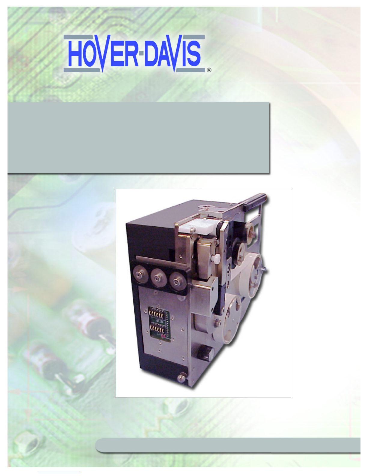
PL1200 Thermal Transfer
PL1200 Thermal Transfer
Printer Product Guide
Printer Product Guide
© 2002 Hover-Davis. All rights reserved.
www.hoverdavis.com
www.hoverdavis.com
Revision 1 6 Aug 02
No. PL1200D-E01
Page 2
World Leader in Component Delivery Systems
Hover-Davis, Inc. has checked the contents of this printed document to verify that it is in
agreement with the product described inside. However, discrepancies can and do occur.
Therefore Hover-Davis, Inc. cannot assume responsibility for complete agreement between
this printed document and the product described inside.
The information contained in this document was thoroughly reviewed before going to print,
and is subsequently reviewed and / or revised on a regular basis. Necessary corrections are
included in future editions.
We welcome any comments or suggestions for improvements.
Technical Publications
Copyright © 2002 by Hover-Davis.
All rights reserved. No part of this book may be reproduced in any form, by print,
photoprint, microfilm, or any other means without written permission from Hover-Davis.
If you need technical information or assistance with
the installation of this product, please call our
Customer Support Center
1-877-812-6830
Monday - Friday, 8:00am - 5:00pm, EST
Email : [email protected]
Page 3

Table of Contents
How to Use This Guide ........................................................................................ 3
Chapter 1: Safety ............................................................................................... 5
1.1 Symbol Index ........................................................................................................ 5
1.2 Safety Labeling and Location Information ............................................................... 5
1.3 Proper Usage ......................................................................................................... 6
1.4 Environmental Requirements .................................................................................. 6
Chapter 2: Introduction ....................................................................................... 7
2.1 PL1200 Features .................................................................................................... 7
2.2 PL1200 Hardware Description ................................................................................. 8
2.3 Docking Station ...................................................................................................... 8
2.4 The Labeler Unit ..................................................................................................... 9
2.5 Mounting and Removing the PL1200 Unit ................................................................. 9
2.6 Mandrels and Reels ................................................................................................ 12
2.7 Labeling Mechanics ................................................................................................. 13
2.8 Sensors .................................................................................................................. 16
2.9 Switches ................................................................................................................. 20
Chapter 3: Installation ......................................................................................... 23
3.1 Installing the PL1200 Docking Station ...................................................................... 23
3.2 PL1200 Software .................................................................................................... 23
Chapter 4: Operations .......................................................................................... 25
4.1 Docking and Removing the PL1200 Labeling Unit ..................................................... 25
4.2 About Changing Media Reels ................................................................................... 26
4.3 Installing the Label Media Reels .............................................................................. 29
4.4 Removing the Label Media Reels ............................................................................ 31
4.5 Installing the Thermal Transfer Media Reels ............................................................ 31
4.6 Removing the Thermal Transfer Media Reels ........................................................... 33
4.7 About the Calibration Sequence .............................................................................. 33
4.8 About Label Positioning Logic ................................................................................. 34
4.9 About Labels and Printing ...................................................................................... 34
(continued on next page)
Page 4

Table of Contents (continued)
Chapter 5: Maintenance ...................................................................................... 35
5.1 Rollers .................................................................................................................. 35
5.2 PL1200 Labeling Unit ............................................................................................. 35
Chapter 6: Troubleshooting ................................................................................ 37
6.1 Print Smudging ..................................................................................................... 37
6.2 Inconsistent Print Length ....................................................................................... 37
6.3 Labels Won’t Calibrate ........................................................................................... 38
6.4 Testing Stock Reel Low Sensors ............................................................................. 40
6.5 Communication Problems ...................................................................................... 40
6.6 No Power to the PL1200 when Docked ................................................................... 40
Chapter 7: Schematics and Wiring ...................................................................... 41
Chapter 8: Spares, Parts and Decommissioning ................................................. 45
8.1 Recommended Spares Kit ...................................................................................... 45
8.2 Decommissioning .................................................................................................. 45
8.3 Product Specifications ........................................................................................... 45
Chapter 9: Technical Bulletins .......................................................................... 47
Page 5

PL1200 Thermal Transfer Printer
This guide is designed to help you install, operate and maintain your PL1200 labeling system.
How to Use This Guide
How to Use This Guide
Each chapter begins with a brief overview followed by a complete discussion of each topic.
Chapter 1: Safety
This chapter provides information on the symbol index used in this manual, safety sticker
information, usage of the PL1200 labeling system and environmental requirements.
Chapter 2: Introduction
This chapter describes the PL1200 labeling unit product features and the hardware
component descriptions to help you become familiar with the PL1200 labeling system.
Chapter 3: Installation
This chapter covers the installation of the PL1200 docking station and labeling unit,
installation of the required software to run the PL1200 labeling system and how to connect
the PL1200 Labeling unit to your PC.
Chapter 4: Operation
This chapter covers removing and replacing the PL1200 labeling unit from the docking
station, changing the label and thermal transfer print media reels, as well as a discussion of
the print operation of the PL1200 labeling unit
Chapter 5: Maintenance
This chapter describes the maintenance required for dependable operation of the PL1200
labeling system.
3
Page 6

This chapter provides information for problem diagnosis and correction for the PL1200 labeling
This chapter contains the schematic and wiring diagrams for the PL1200 labeling system.
This chapter contains a parts list, information on decommissioning the PL1200 labeling unit, and
This chapter contains any technical information for the PL1200 labeling system that has been
PL1200 Thermal Transfer Printer
How to Use This Guide
Chapter 6: Trouble shooting
unit.
Chapter 7: Schematics & Wiring
Chapter 8: Spare Parts, Decommissioning, and Product Specifications
the product specifications for the PL1200 labeling system.
Chapter 9: Technical Bulletins
issued by the factory after the release of this manual.
4
Page 7

Safety
1
Page 8
PL1200 Thermal Transfer Printer
1.2 Safety Labeling and Location Information
Safety
Chapter 1: Safety
This chapter provides information on the symbol index used in this manual, safety labeling
and location information for the PL1200 labeling unit, proper usage of the PL1200 labeling
system and environmental requirements for reliable operation of the PL1200 labeling unit.
1.1 Symbol Index
The symbols listed below are found within this manual.
CAUTION
WARNING
CAUTION : SEE EXPLAINATION IN MANUAL.
WARNING : POSSIBLE PINCH POINTS KEEP HANDS CLEAR.
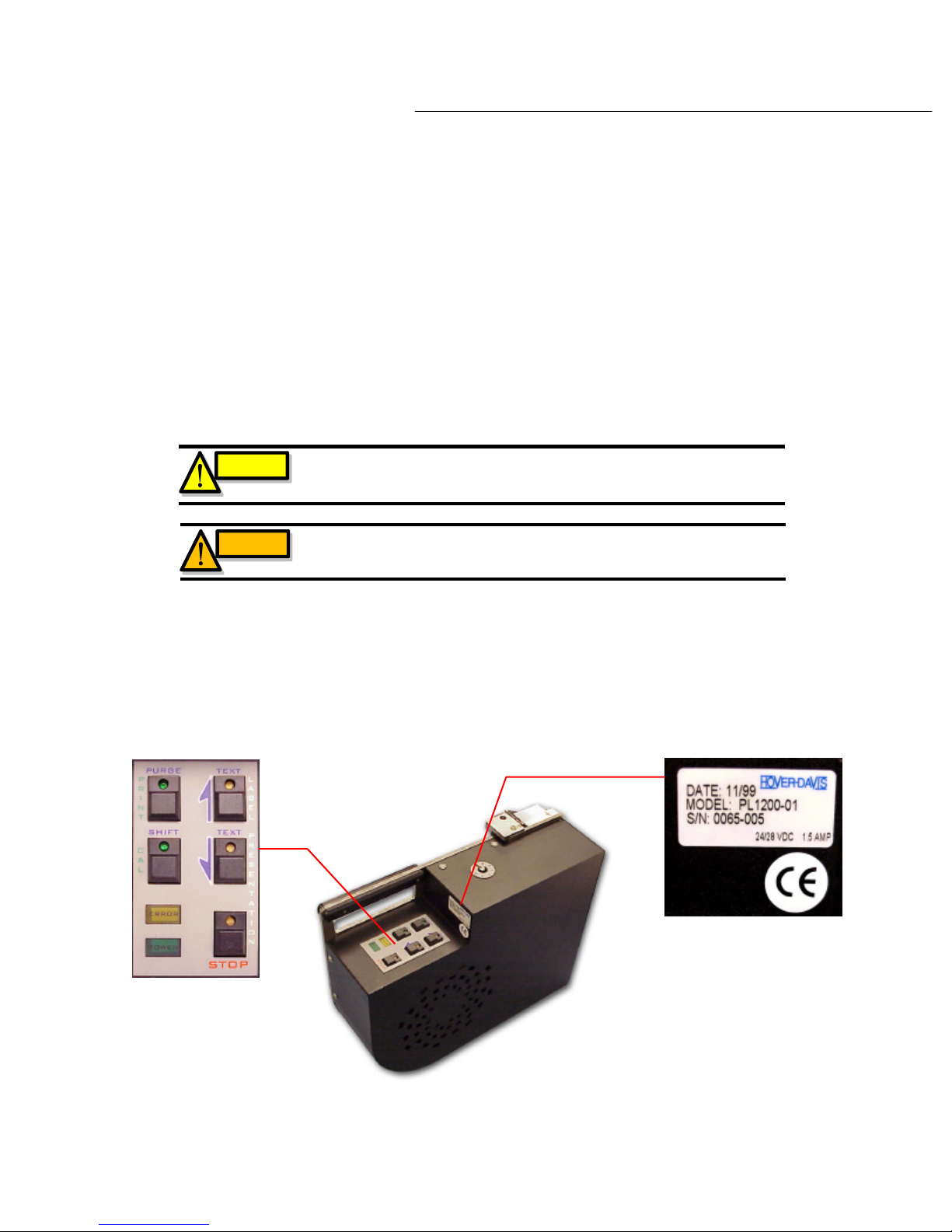
Diagram 1.2a show the location of operational and safety-labeling information found on the
PL1200 labeling unit.
5
Page 9

PL1200 Thermal Transfer Printer
The PL1200 labeling system is expressly designed and intended to be used to print and present
It is intended to manipulate label dimensions that range in length from .250” to 1.500” and range
Safety
1.3 Proper Usage
labels for automated labeling applications.
in width from .125” to .500”.
It is recommended that Identco brand labels be used with the PL1200 labeling unit. For
information on ordering Identco brand labels, please contact your local distributor or contact
Identco directly at 1-800-533-2559. For information on the use of other labels, please contract
Hover-Davis Inc.
Do not use this device for any other purpose than that for which it is intended. Usage of this
device for any other purpose than that which is stated in this manual may cause injury and/or
damage to the unit. To do so will void all warranties expressed or implied.
1.4 Environmental Requirements
Install the PL1200 labeling unit in an area where the ambient temperature remains within the
range of 10 to 35 degree C and the humidity does not exceed 75% RH (with no condensation).
Failure to comply with these conditions can cause trouble in the electrical system and/or lead to
machine malfunctions.
Do not install the PL1200 labeling unit in direct sunlight as this can increase the PL1200 labeling
units’ temperature and may effect the optical sensors in the labeling unit, causing adverse and
erratic labeling operations and accuracy.
6
Page 10

Introduction
2
Page 11

PL1200 Thermal Transfer Printer
in greater detail the product features and the hardware component
•
Introduction
Chapter 2: Introduction
The PL1200 labeling system is a thermal transfer printer and label presenter in one and is
designed to print and present your label requirements on demand. Label text is downloaded
from the host computer, printed and then presented in a “zero que’ environment, thereby
eliminating the need for pre-printed labels and leaders.
With the PL1200’s compact size and light weight design, it can easily integrated into your
automated manufacturing environment. It snaps on and off the docking base with ease to
provide quick and easy loading of label and print media reels.
The PL1200 labeling system has been designed with you in mind, to provide simple
installation and integration into your automated environment.
This chapter will describe
descriptions so that you can become familiar with the PL1200 labeling system.
2.1 PL1200 Features
The PL1200 labeling system provides the following features:
•
Print speeds of 1.5 seconds per inch at 180 x 200 DPI.
•
A refresh rate of 4.5 seconds depending on label size/length.
•
The labeling unit is capable of printing bar codes and date stamps.
•
Precision repeatability of label presentation for pick up by the host machine with +/.020”.
•
No hand tools are needed for installation or removal of the labeling unit to/from the
docking station when mounted to the host machine.
•
All power is delivered to the docking station eliminating the need to power the labeling
unit on and off to replace label or print media reels.
•
The labeling unit snaps on and off the docking station with ease providing complete
access for quick label and print media reel changes.
RS232 interface for ease of use with Windows based 3rd party software.
7
Page 12
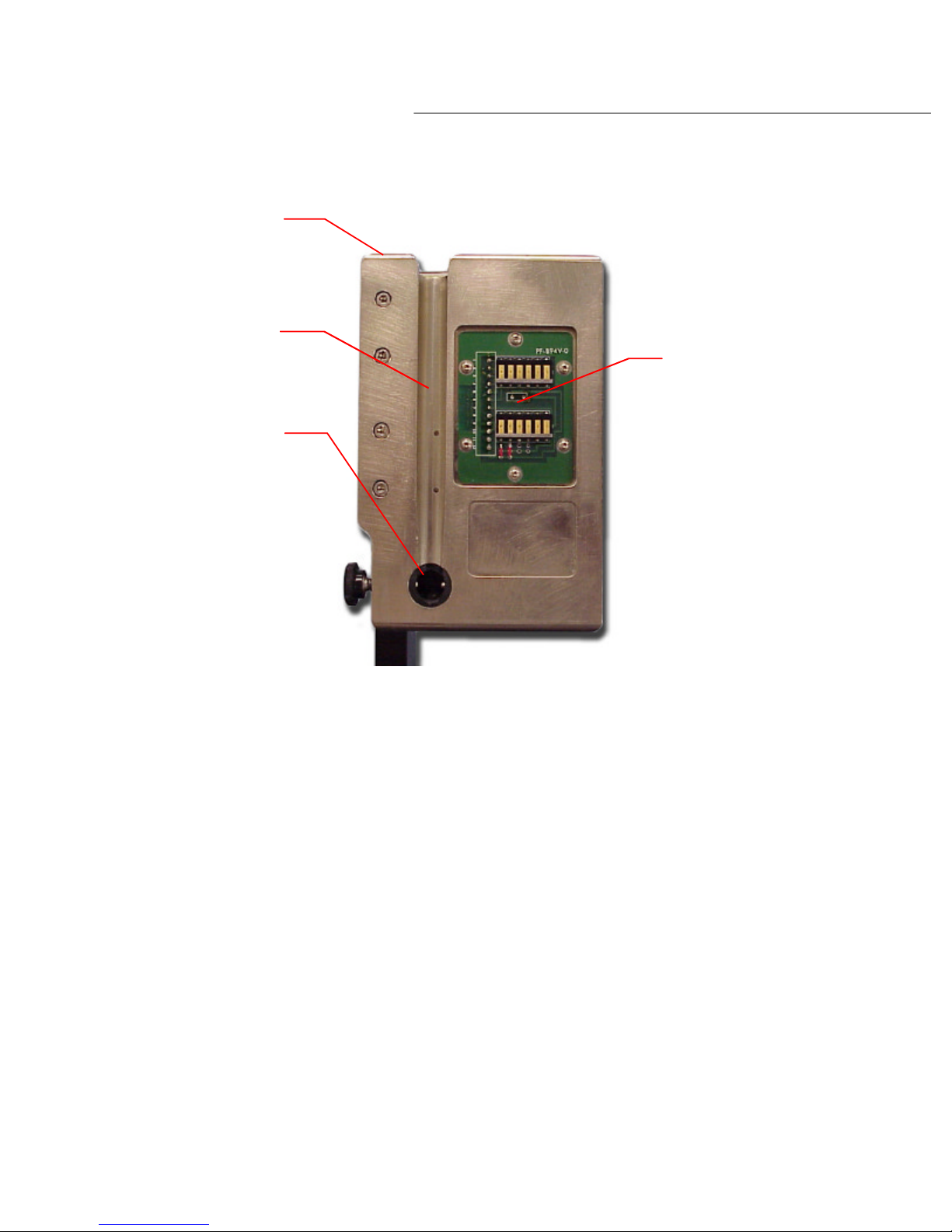
This section will describe the PL1200 docking station and labeling unit in detail to help you
The two major components of the PL1200 labeling system are the dockin
please refer to the BP3100/BP3500 manual. The docking station consists of the docking plate and
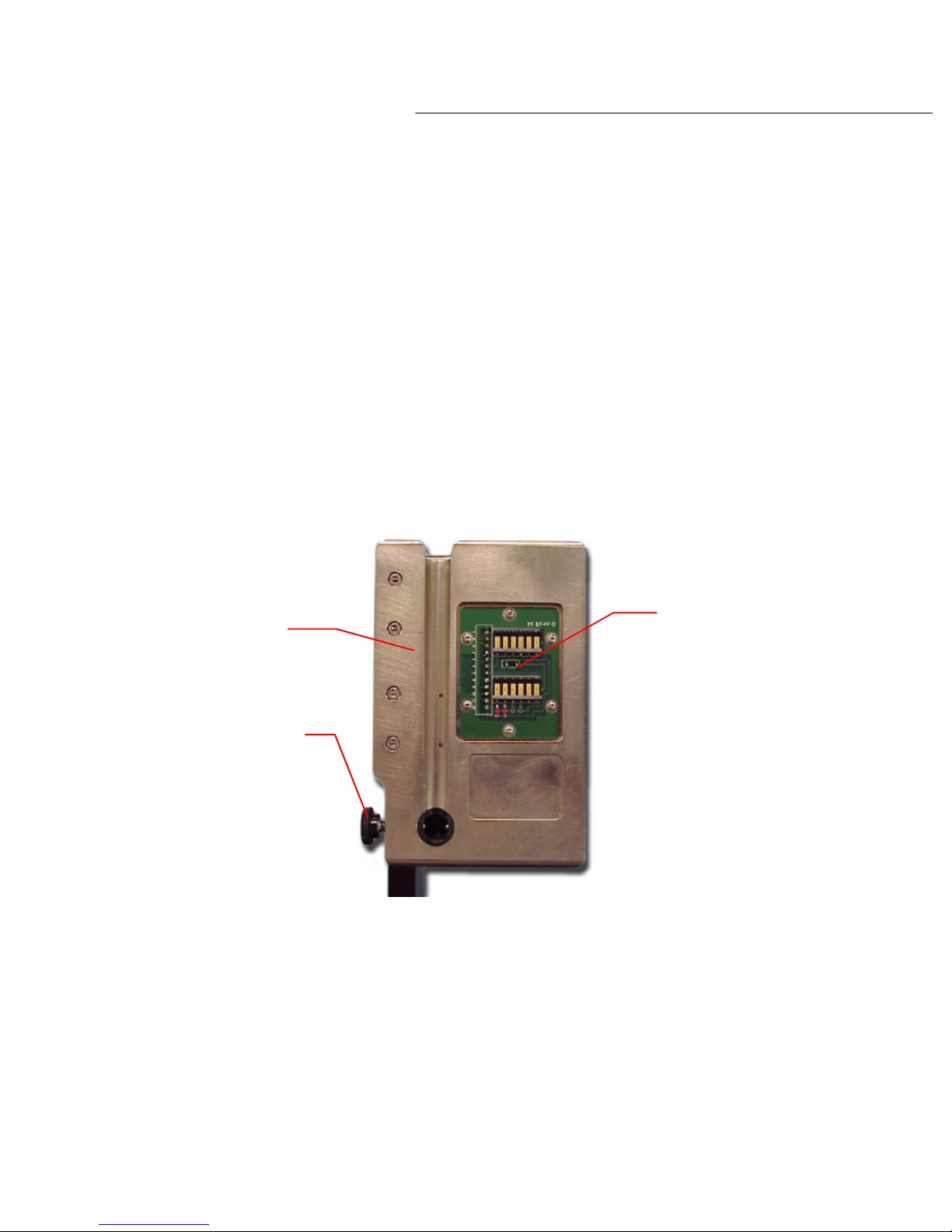
The docking plate has a notched edge along the top and a groove down the front with an
PL1200 Thermal Transfer Printer
Introduction
2.2 PL1200 Hardware Description
become familiar with the PL1200 system.
2.3 Docking Station
g station and the
labeling unit. The docking station is designed to be mounted to the host machine.
All power and communications with the labeling unit are provided through the docking station
mounted within the BP3100/BP3500. For more information on the BP3100/BP3500 system,
the docking plate PCB as shown in diagram 2.3a below
Docking plate PCB
Docking Plate
Lock down knob
Diagram 2.3a
alignment bushing at the base as shown in diagram 2.3b. These features enable the user to
remove and return the labeling unit to the docking plate as often as needed without
compromising the precision with which the labels are dispensed.
8
Page 13
The PL1200 labeling unit for purposes of discussion will be divided into four areas. The first
The mounting points on the PL1200 labeling unit consist of a dock clamp block, a guide pin and a
Notched edge
Groove
Alignment bushing
PL1200 Thermal Transfer Printer
Introduction
Docking plate PCB
Diagram 2.3b
2.4 The Labeler Unit
covers mounting and removing the labeler to or from the docking station, the second will cover
the mandrels and reels, the third area covers the labeling mechanics and the fourth describes
sensors and switches.
2.5 Mounting and Removing the PL1200 unit
tooling ball as shown in diagram 2.5a.
9
Page 14
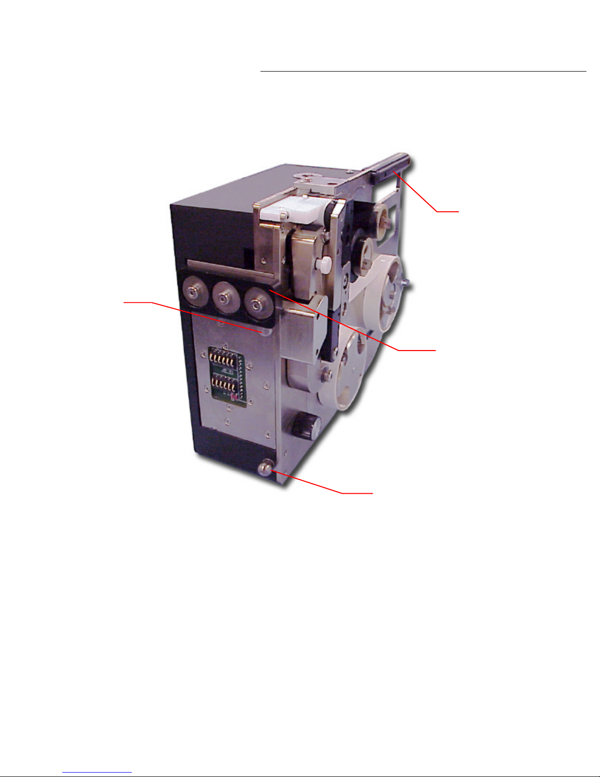
To mount the labeling unit to the docking station, align the guide pin within the top of the groove
in the dock base plate and place the bottom edge of the dock clamp block onto the notched edge
pin lined up to the dock base plate,
To remove the labeler from the docking station, firmly grasp the handle found on the top of th
Guide pin
PL1200 Thermal Transfer Printer
Introduction
Handle
Dock clamp block
Diagram 2.5a
of the dock base plate. With the dock clamp block and guide
the tooling ball with snap into place and the labeling unit is now mounted onto the docking plate
as shown in diagram 2.3b.
labeling unit. Lift the labeling unit up and out to release the tooling ball from the alignment
bushing. The labeler can now be lifted out and away from the docking station.
Tooling ball
e
10
Page 15
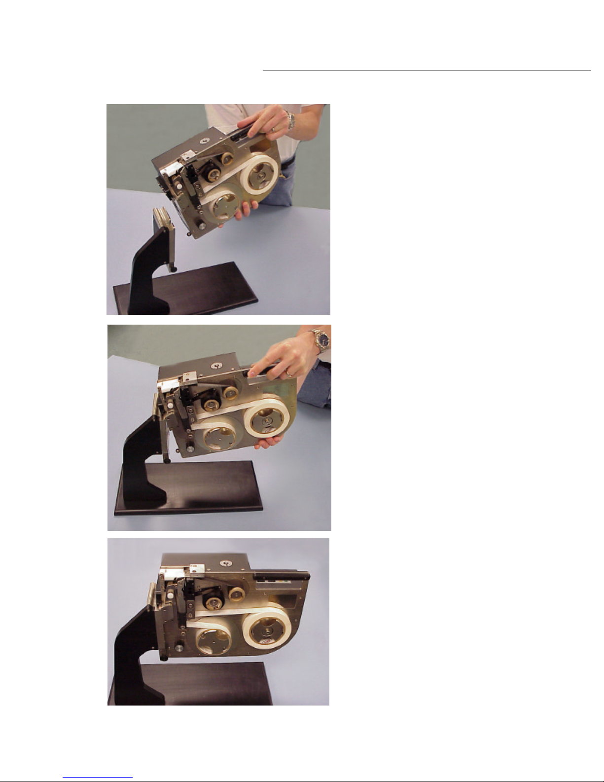
PL1200 Thermal Transfer Printer
Introduction
This photo shows how easy
it is to remove the labeling
unit from the docking station.
This photo shows how to
line up the labeling unit
with the docking station
for easy installation.
This photo shows the
labeling unit mounted
to the docking station.
Diagram 2.5b
11
Page 16
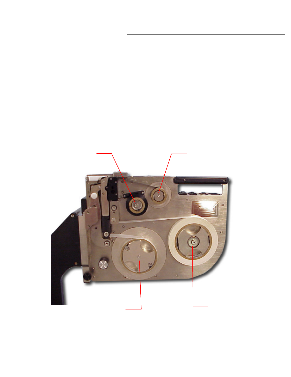
The PL1200 labeling unit has four mandrels. These mandrels accommodate the reels of material
contain the used ribbon and label material reels for collection. Please see diagram 2.6a
PL1200 Thermal Transfer Printer
Introduction
2.6 Mandrels and Reels
for labeling and printing. Two mandrels are dedicated to the thermal transfer print ribbon reels,
these are the smaller of the two sets, and the two larges ones are for the label reels.
Each set of mandrels consists of a ‘stock’ mandrel and a ‘take-up’ mandrel. The ‘stock’ mandrels
hold the thermal transfer tape ribbon reel and the label ribbon reel for dispensing. The ‘take up’
mandrels
below
Thermal tape
'stock' mandrel
Thermal tape
'take-up' mandrel
Label 'take-up'
mandrel
Diagram 2.6a
12
Label 'stock'
mandrel
Page 17

fastening/unfastening of reels to the mandrels. Diagram 2.6b show the pressure clips in both the
‘open’ and ‘closed’ position.
The PL1200 labeling unit contains seven major components for printing and dispensing labels for
PL1200 Thermal Transfer Printer
Introduction
Each of the mandrels contains two flexing pressure clips, which provide quick and easy
Pressure clip in 'closed' position
locks media reel in place on the mandrel
Pressure clip in 'open' position,
media reels can be removed
from or returned to the mandrel
Diagram 2.6b
2.7 Labeling Mechanics
pickup by your host machine. This section will describe in detail the hardware components that
make up the PL1200 labeling unit. The hardware descriptions and location information are
provided to help you familiarize yourself with the PL1200 labeling unit for operation and
maintenance.
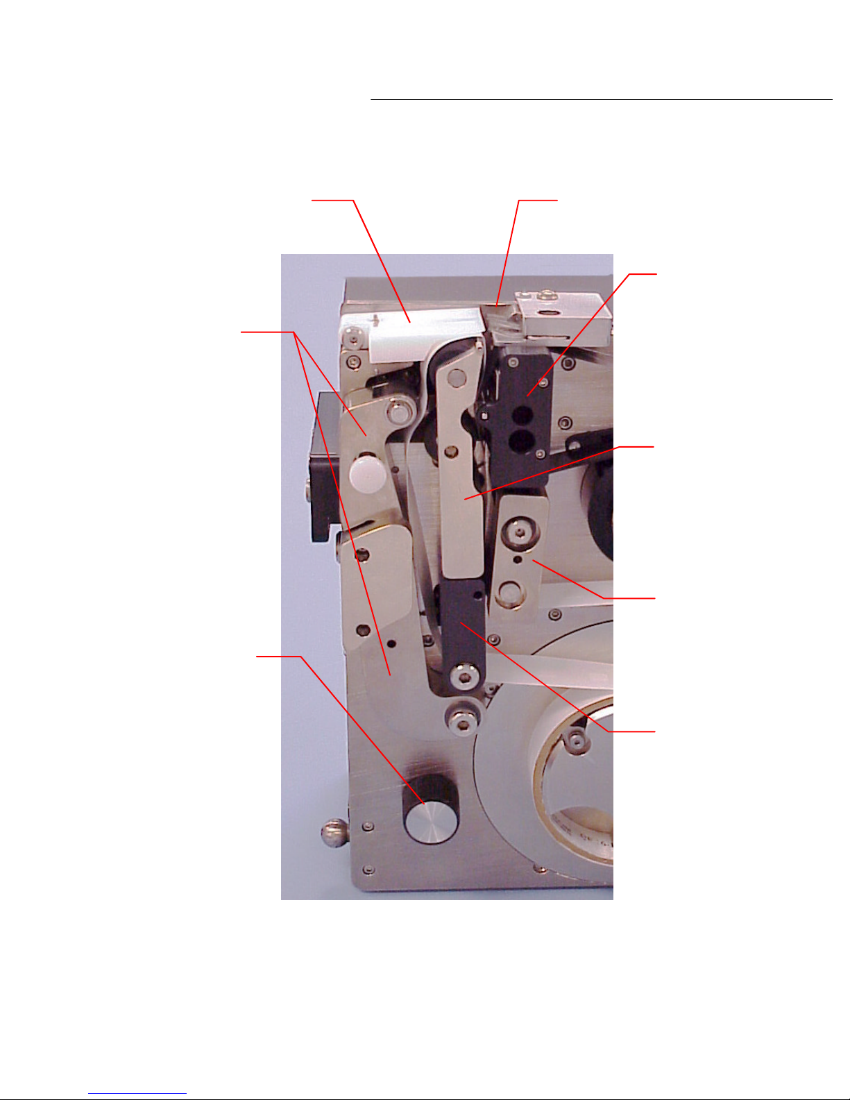
Following this section you will find a photograph that shows in detail all of the parts information
described in this section. The number found next to each part description corresponds to the
number of the part shown in the photograph in diagram 2.7a
13
Page 18
PL1200 Thermal Transfer Printer
advance the label tape. This assembly also contains the ‘drive arm assembly’. By pulling
and thermal transfer print tapes into position. When the drive arm ‘lock knob’ is pressed,
clockwise. The PL1200 is not
turned clockwise, both sets of mandrels will spin and the thermal transfer and label tapes will
Introduction
1. The ‘print head cover’. This houses the thermal print head and also contains a guide
roller or the thermal print tape and label tape.
2. The ‘label tension block’ is located just below the ‘print head cover’. It contains a single
roller and provides for the tensions of the label tape.
3. Located along side the ‘print head cover’ and ‘label tension block’ is the ‘transfer roller
arm’. It contains two rollers. Then it pivots into place and pressure is applied by the
rollers to the label and thermal print tape for printing and tape advancement.
4. Below the’ transfer roller arm’ is the ‘transfer pivot block’. It contains a single roller,
which supports the ‘transfer roller arm’. It guides the used label tape to the ‘take up’
mandrel.
5. Located alongside of the ‘transfer pivot block’ and the ‘transfer roller arm’ is the ‘drive
arm assembly’. It contains a single roller that provides the rotation force needed to
and swinging the drive arm ‘lock knob’ to the left, the ‘drive arm assembly’, ‘transfer
pivot block’ and ‘pivoting roller block’ open to allow the operator to load both the label
the ‘drive arm assembly’, ‘transfer pivot block ‘ and ‘pivoting roller block’ snap back into
operating position.
WARNING
6. The white Teflon part found directly above ‘drive arm assembly’ and ‘pivoting roller block’ is
the ‘label deck’. The labels that have been printed are placed here for retrieval either by
hand or your pick and place nozzle. The ‘anti static brush” is located along side the ‘label
deck’.
7. In the lower left corner of the labeling unit is the ‘manual advance knob’. When this knob is
be advanced.
CAUTION
WARNING : POSSIBLE PINCH POINTS KEEP HANDS CLEAR.
DO NOT spin the ‘manual advance knob’ counterdesigned to spin in this direction.
14
Page 19
5 Drive arm assembly
PL1200 Thermal Transfer Printer
Introduction
6 Label deck Anti-static brush
1 Print head cover
3 Transfer roller arm
7 manual advance knob
2 Label tensioner block
4 Transfer pivot block
Diagram 2.7a
15
Page 20
PL1200 Thermal Transfer Printer
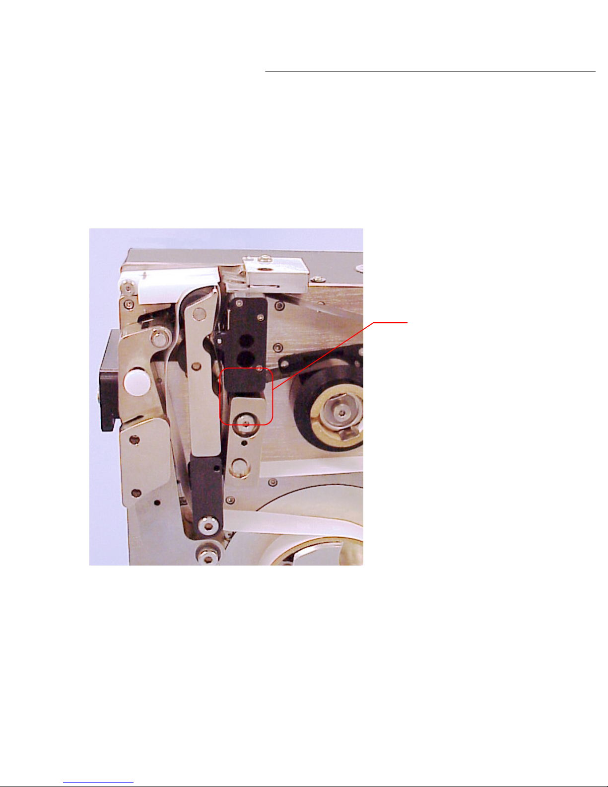
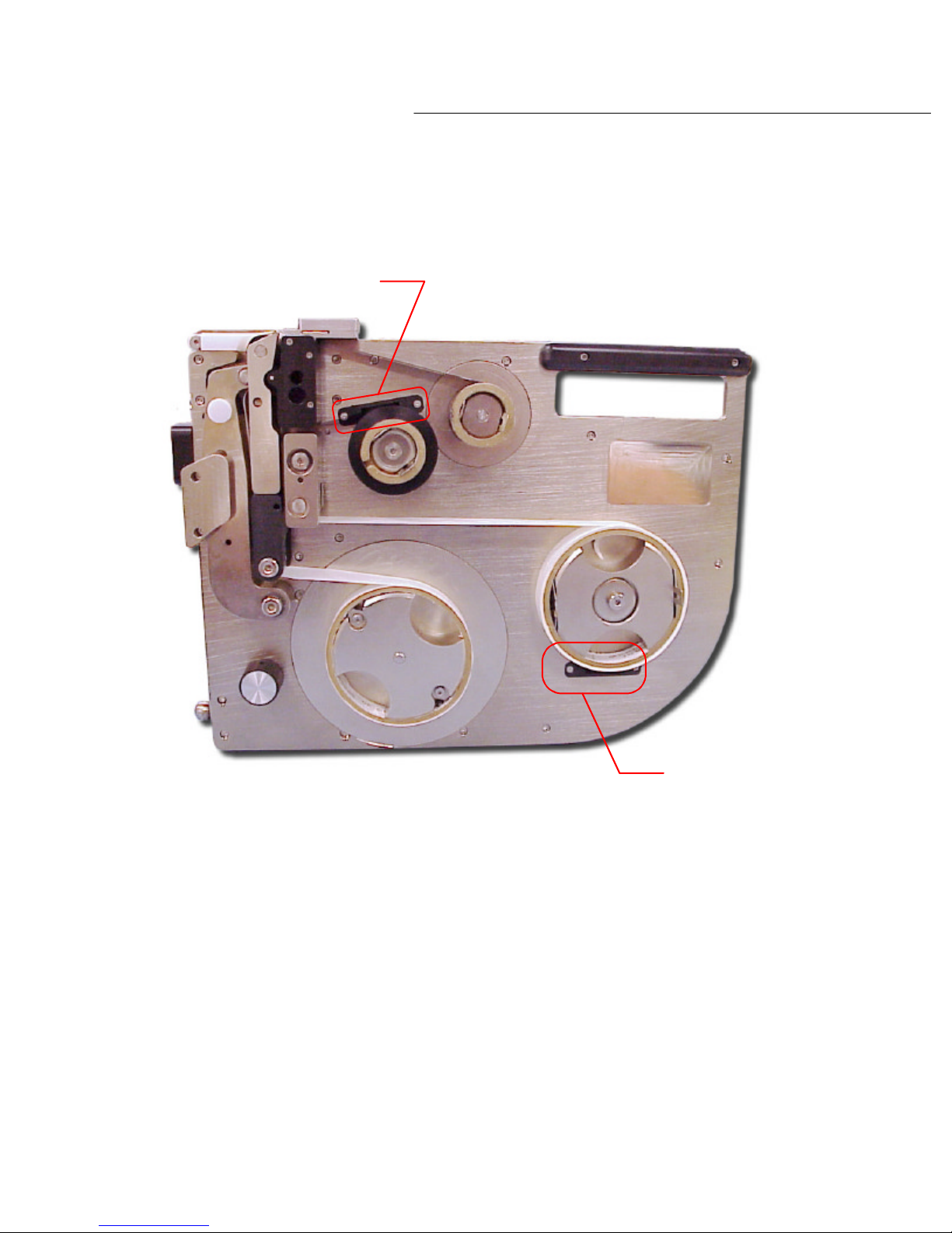
There are five sensor locations in the PL1200 labeling unit. The ‘ribbon tape’ sensor is located
The second sensor is the ‘label alignment’ sensor. This sensor is located between the ‘label tension
labels to properly align the label for printing and pre
sentation.
Introduction
2.8 Sensors
between the ‘print head cover’ and the ‘label tension block’ (see diagram 2.8a). This sensor is
used for detection of the thermal transfer ribbon tape. If a ‘no tape’ condition is detected the
PL1200 unit will not print or present labels.
'Ribbon tape'
sensor
Diagram 2.8a
block’ and the ‘transfer roller arm’ (see diagram 2.8b). The ‘label alignment’ sensor detects the
16
Page 21
PL1200 Thermal Transfer Printer
The third sensor is the ‘thermal transfer ribbon low’. It is located to the left above the thermal
The fourth sensor is the ‘label tape low’ sensor and is located below the label stock mandrel as
Introduction
'label alignment'
sensors
Diagram 2.8b
tape stock mandrel as shown in diagram 2.8c. When the thermal transfer stock reel becomes
low the condition is detected by this sensor. Once detected the yellow error light on the switch
bank illuminates alerting the operator that the stock reel may be low.
shown in diagram 2.8c. When the label tape stock reel becomes low, this condition is detected
by this sensor. Once detected, the yellow error light on the switch bank will illuminate alerting
the operator that the label tape stock reel maybe low. Please note that when a label tape low
condition is encountered, the labeling unit can dispense 500 or more labels depending on the
label size being used, so a low condition detection is not indicative of an empty label tape reel.
17
Page 22
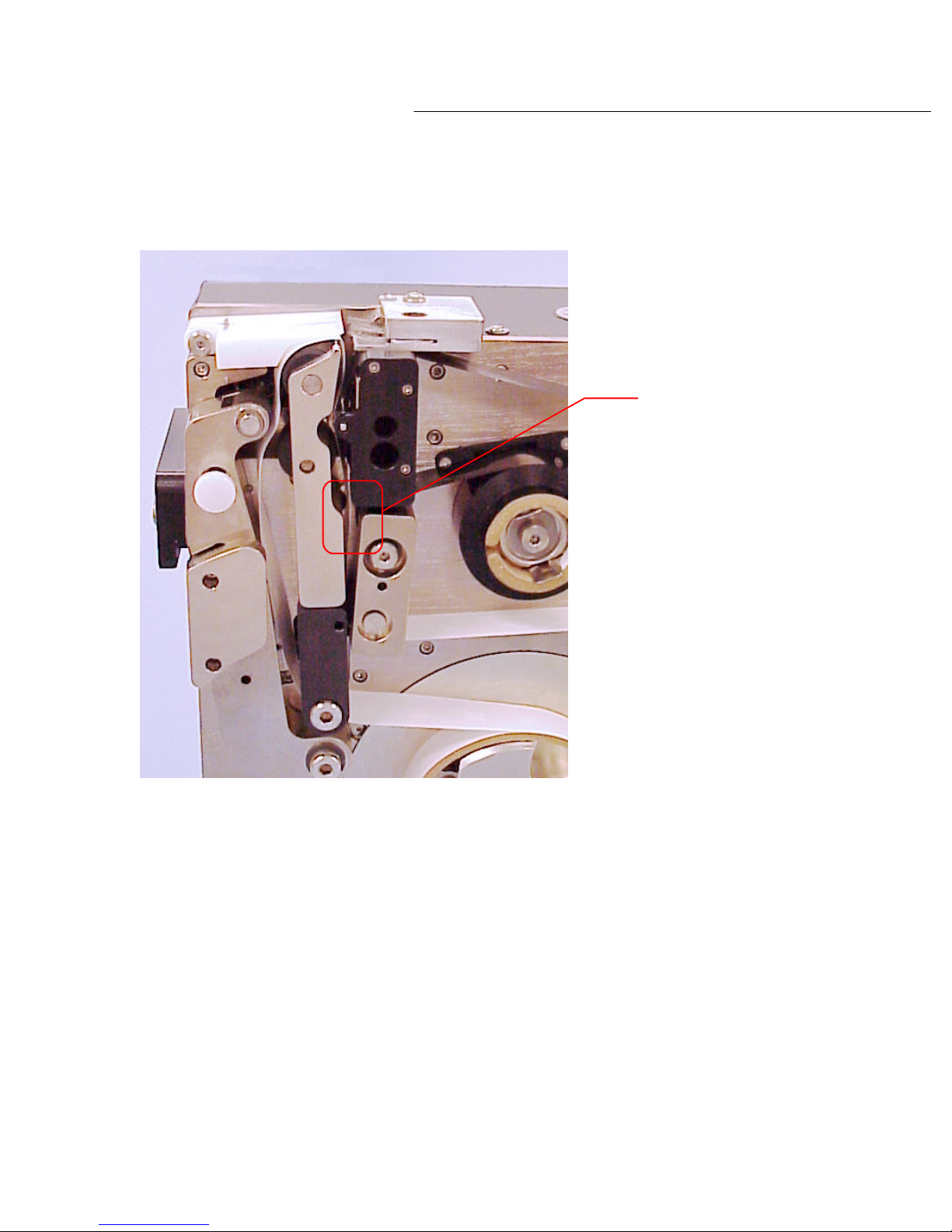
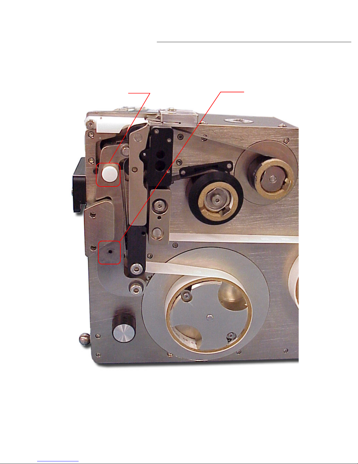
The fifth sensor is the ‘ drive arm open’ sensor. This sensor is located within the drive arm
'Thermal transfer tape low' sensor
PL1200 Thermal Transfer Printer
Introduction
Diagram 2.8c
mechanism. When the drive arm is set to the open position for leading of media reels, this
sensor is activated (see diagram 2.8d). When the sensor is active, the labeler will be unable to
perform a calibration sequence until the drive arm is set in the closed position. Once closed the
sensor will go off and a calibration sequence can now be performed.
18
'Label tape low' sensor
Page 23
PL1200 Thermal Transfer Printer
Introduction
Drive arm lock knob
Sensor location
Diagram 2.8d
19
Page 24
PL1200 Thermal Transfer Printer
labeling unit. This is found on
The switches found on the switch bank are multi
The switch on the top right corner of the switch bank ha
s a purple arrow pointing forward. This is
Introduction
2.9 Switches
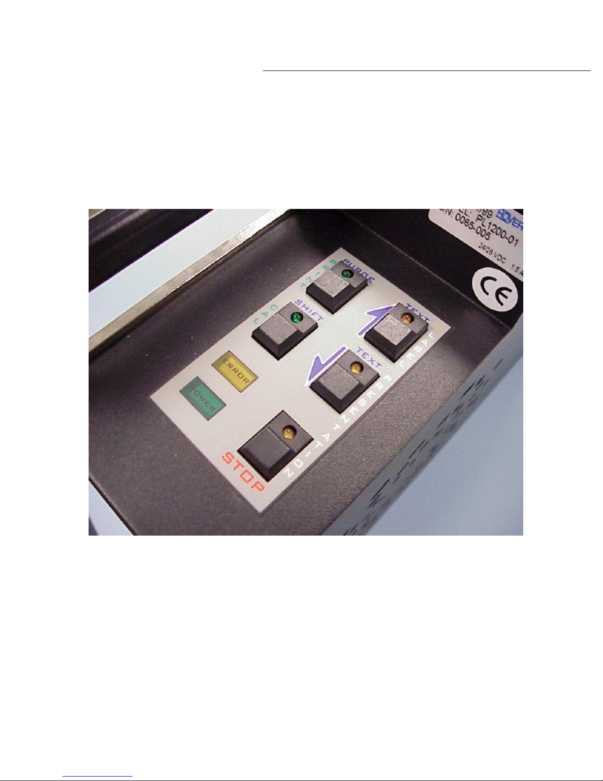
Next to be discussed is the switch bank found on the PL1200 seriesthe top of the labeling unit. The switch bank consists of five switches. Each switch contains an
LED indicator as shown in diagram 2.9a.
function as the vertical labels on the switch indicate – The 2 switches on the upper right hand
side of the switch bank labeled ‘LABEL PRESENTATION’ are used to manually advance or retract
the label position for pickup by the host machine. When using these switches for adjusting
labels, it is important to adjust presentation first then adjust print position.
the ‘LABEL ADVANCE’ SWITCH. Each time this switch is depressed, the next label to be
dispensed for pickup will be advanced in approximately .005-inch increments.
Diagram 2.9a
-functional. In the first mode the switches
20
Page 25

PL1200 Thermal Transfer Printer
The second switch found directly below the ‘LABEL ADVANCE’ switch is the ‘LABEL RETRACT’
The switch in the lower right corner of the switch bank is the ‘STOP’ switch. When this switch is
advance the labels. It is during calibration that the labels are measured and aligned for printing.
Three or more labels will be dispensed at this point.
occurred, or when label adjustments are being made which will require a calibration sequence be
Introduction
switch. These switches have a purple arrow that points backwards. Each time this switch is
depressed, the next label to be dispensed for pick up will be retracted in approximately .005inch increments.
depress the labeling unit is reset. Once this switch is depressed you will notice the ‘CAL’
(calibration) switch LED will begin blinking. This indicates the labeling unit has been reset and a
calibration sequence needs to be performed. The button located in the left center of the switch
bank is the ‘CAL’ switch. This switch when depressed will initiate the calibration sequence and
When the PL1200 series-labeling unit is powered up, the ‘STOP’ switch is pressed or an error
condition is encountered, the LED indicator on the ‘CAL’ switch will start blinking. This is to alert
the operator that a calibration sequence needs to be performed. Once the ‘CAL’ switch has been
depressed, the LED indicator light will stay on until the next time a power sequence or reset has
performed.
Above the ‘CAL’ switch on the switch bank is the ‘PRINT’ nudge switch. When depressed it will
initiate a print command to the labeling unit and a label is ready to print.
In the second mode, the function of the switches is different, as denoted by the horizontal label
above each switch. By depressing and holding down the ‘SHIFT’ switch, and then depressing one
of the ‘LABEL PRESNTATION’ switches, the operator can adjust the print on the label, in relation
to the leading edge of the label.
21
Page 26
PL1200 Thermal Transfer Printer
the switches enough times, the setting of the print to the leading edge of the label will eventually
These adjustments will be seen on the second label to be dispensed following the actual
To reset t
The ‘PURGE’ function key on the switch bank is currently disabled at this time.
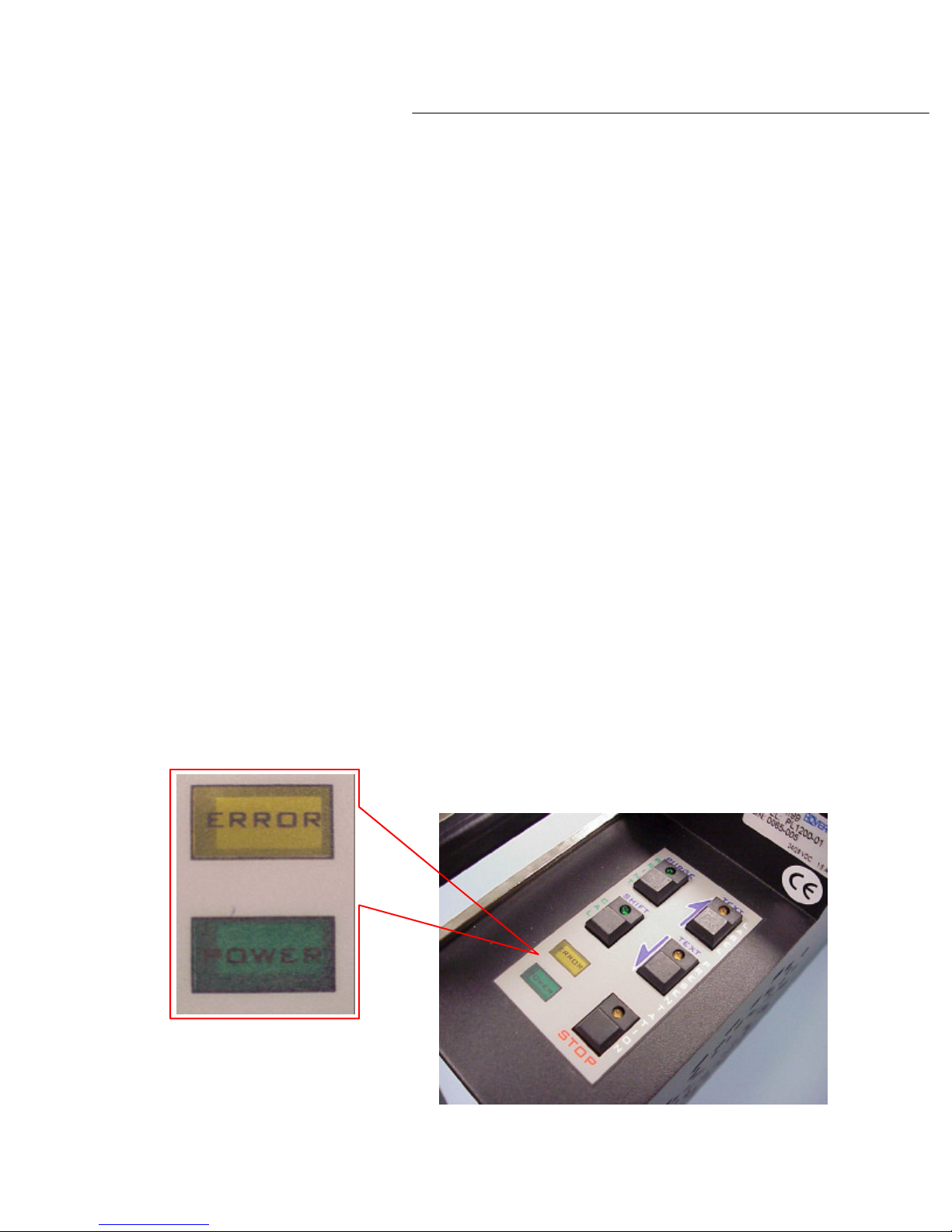
The green indicator labeled ‘POWER’ is lit when the labeling unit is successfully docked to the
Introduction
With the ‘SHIFT’ switch depressed and while concurrently depressing the ‘LABEL ADVANCE’
switch, the print on the label can be adjusted forward in approximately .005-inch increments.
With each depression of the ‘LABEL ADVANCE’ switch, an additional increment will occur.
With the ‘SHIFT’ switch depressed and while concurrently depressing the ‘LABEL RETRACT’
switch, the print on the label will be adjusted backward in approximately .005-inch increments.
Again, with each depression of the ‘LABEL RETRACT’ switch, an additional increment will occur.
In both of the above described sequences the program logic is set up in a loop. By depressing
return to its original start position.
adjustment via the switches. If you calibrate the labeling unit immediately following each
adjustment, the changes will be immediate.
he switches to the original factory settings, push and hold the ‘STOP’ switch while
concurrently pushing and holding down the ‘LABEL ADVANCE’ and ‘LABEL RETRACT’ switches.
Next, release the ‘STOP’ switch, then release the ‘LABEL ADVANCE’ and ‘LABEL RETRACT
switches.
In addition to the switches on the display panel there are two LED indicators. The yellow
indicator labeled ‘ERROR’ will illuminate when errors are encountered, or when ‘low tape’
conditions on either stock reels are detected.
adapter (see diagram 2.9b).
Diagram 2.9b
22
Page 27

Installation
3
Page 28

PL1200 Thermal Transfer Printer
Installation
Chapter 3: Installation
This chapter will cover the installation of the PL1200 labeling system to the host machine,
installation of the software needed to operate the PL1200 labeling unit and how to connect
the PRO Labeling 1200 labeling unit to your PC.
3.1 Installing the PL1200 Docking Station
Mounting of the docking station to the host machine will vary from site to site, depending on
the customer’s requirements.
For further information regarding site-specific mounting requirements, contact your local
representative or the factory.
3.2 PL1200 Software
The PL1200 labeling unit comes with the Brother P-Touch installation disks.
Labels are created using the Brother P-Touch software. Please see the Brother P-Touch
software manual for more information.
23
Page 29

24
Page 30

Operations
4
Page 31
PL1200 Thermal Transfer Printer
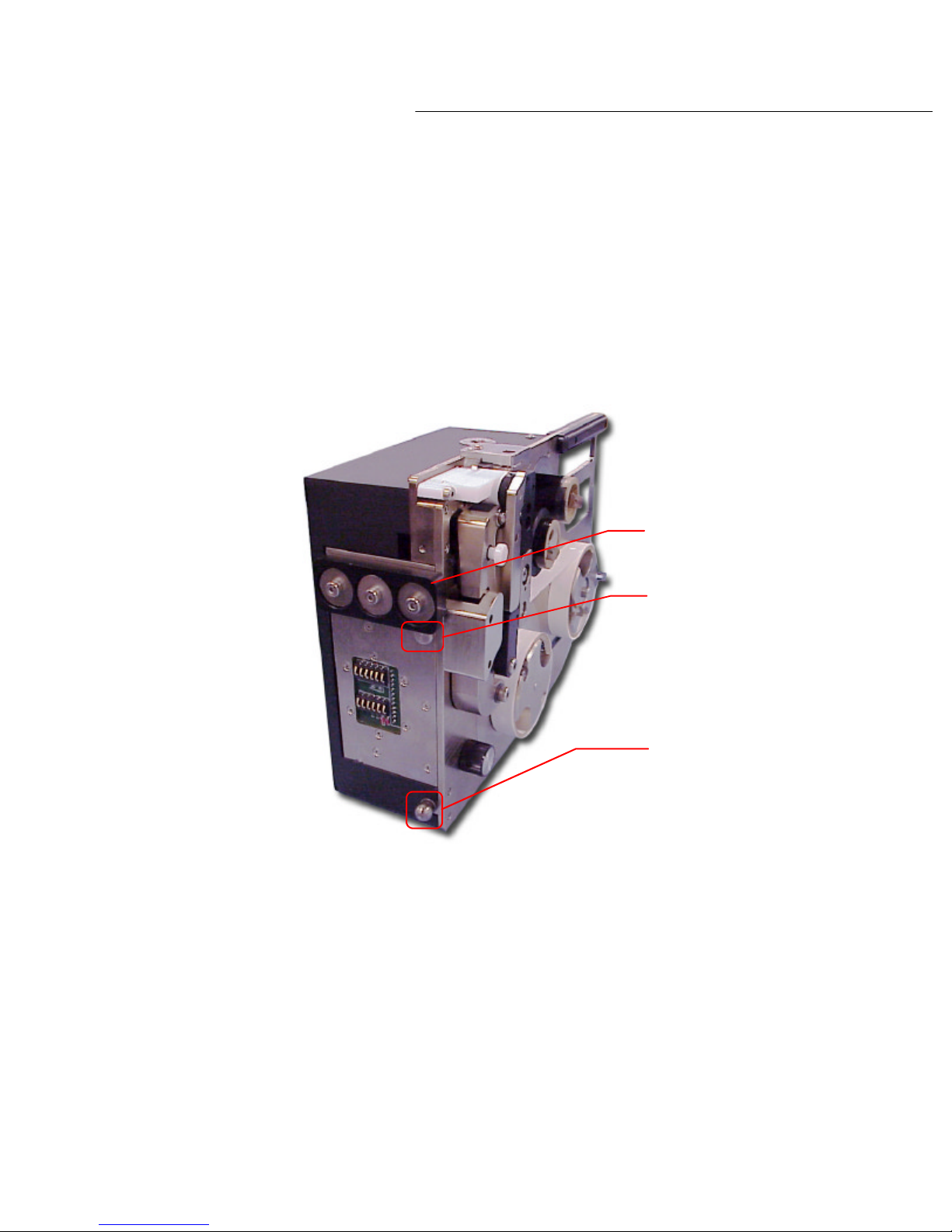
The mounting points on the PL1200 labeling unit consist of a dock clamp block, a guide plate
To dock the labeling unit to the docking station, align the guide pin within the top of the groove
To remove the labeler from the docking station, firmly grasp the handle found on the top of the
Operations
Chapter 4: Operations
This chapter will cover docking and removing the PL1200 labeling unit from the host
machine, changing the label and thermal transfer print tapes, creating editing and printing
labels with the PL1200 labeling system.
4.1 Docking and Removing the PL1200 Labeling Unit
pin and a tooling ball. Please see diagram 4.1a below.
Dock clamp block
Guide pin
Tooling ball
Diagram 4.1a
on the dock plate and place the bottom edge of the dock clamp block onto the notched edge
along the top plate of the docking station.
Once the dock clamp block and guide pin are lined up correctly, the tooling ball will snap into
place and the PL1200 labeling unit will power up.
labeling unit. Lift the labeling unit up and out to release the tooling ball from the alignment
bushing. The labeler can now be lifted out and away from the docking station.
25
Page 32
PL1200 Thermal Transfer Printer
Operations
4.2 About Changing Media Reels
Before label media reels can be changed and for ease of changing thermal transfer print and
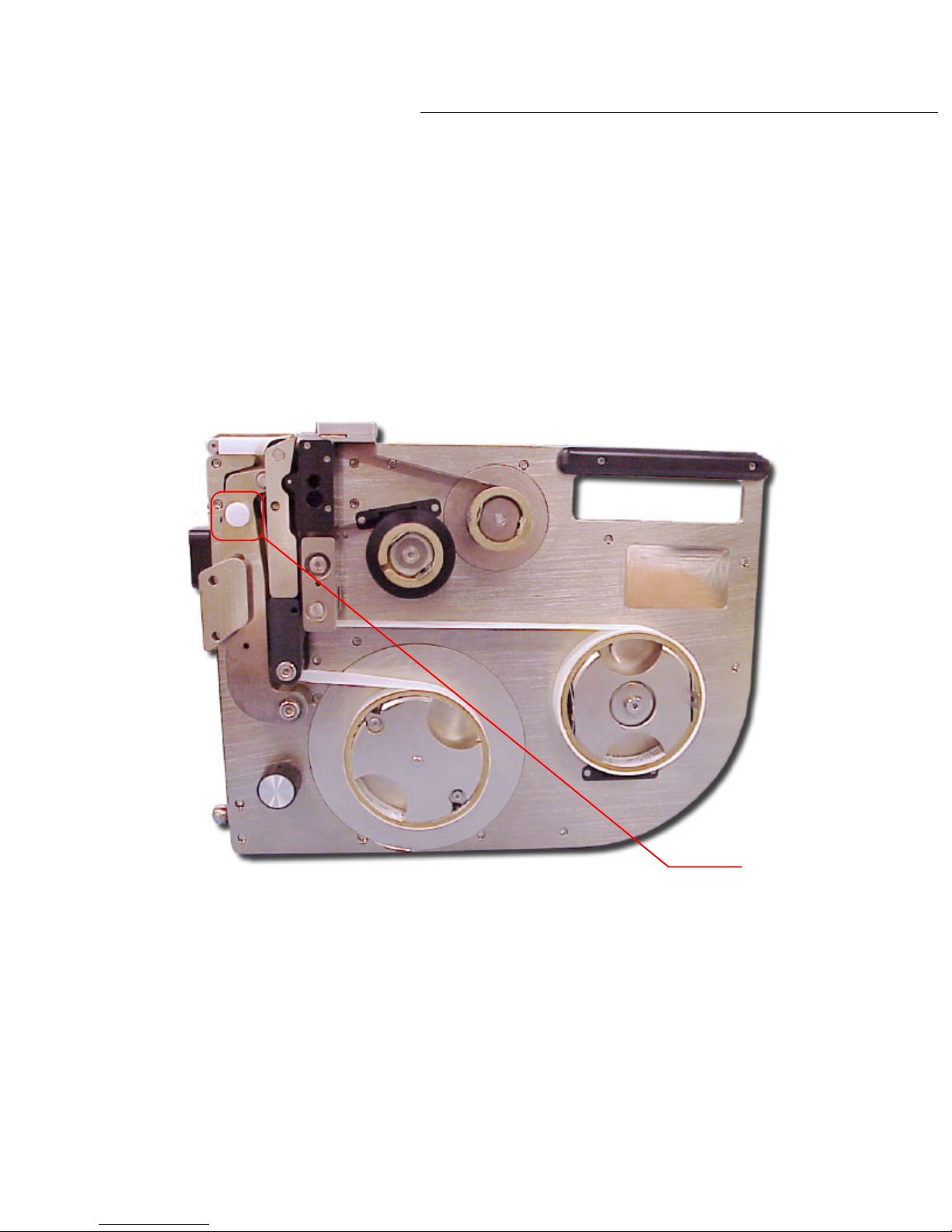
label tape, always remove the PL1200 labeling unit from the docking station. Once removed, lay
the labeling unit on its back. This makes it easier to handle the label media reels. Before the
reels can be removed, the drive arm ‘lock knob’ need to be set in the open position as seen in
diagram 4.2a.
Diagram 4.2a
26
Drive arm
'lock knob'
Page 33
PL1200 Thermal Transfer Printer
To set the knob to the open position, hold the unit firmly by the handle and pull the drive arm
‘lock knob’ out. While holding the knob in the out position, pull the knob to the left until the drive
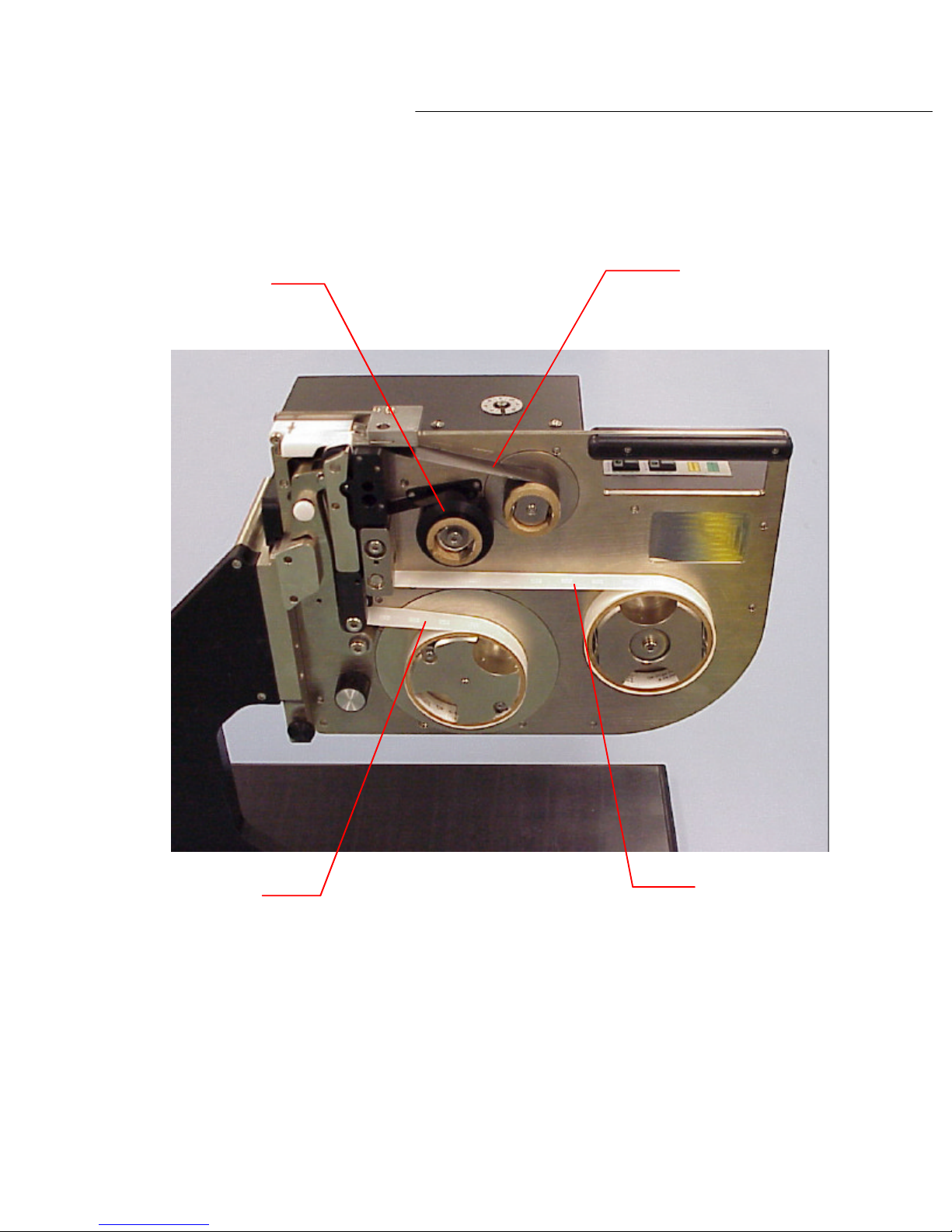
The proper position of the reels on the mandrels, whether it is the ‘stock’ reels or the ‘take
4.2c
Operations
arm locks open.
You will now notice that the ‘drive arm’ assembly and ‘transfer roller arm swing out slightly so
that you can easily remove or slide the label or print media type into position.
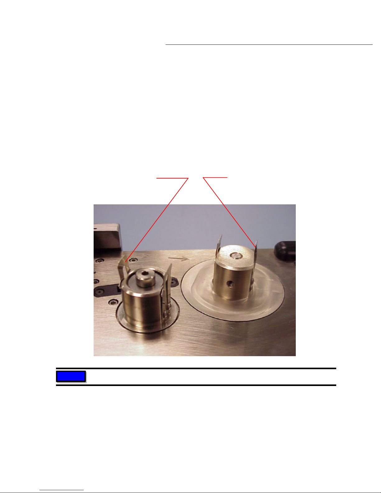
Snap both set pressure clips on the label and /or ribbon mandrels to the open position by
pressing the clips inward or towards the mandrel (see diagram 4.2b below). One this is done,
you are ready to remove or install the label or print media reels.
Pressure clip in 'closed' position
locks media reel in place on the mandrel
Pressure clip in 'open' position,
media reels can be installed
or removed
Diagram 4.2b
NOTE
reels is always with the media being fed from or onto the top of the reel as shown in diagram
Clips shown are ribbon mandrels
27
-up’
Page 34
PL1200 Thermal Transfer Printer
Operations
Ribbon feeds from
top of stock reel
Ribbon feeds onto
top of take up reel
Labels feed onto
top of take up reel
Diagram 4.2c
Labels feed from
top of stock reel
28
Page 35
PL1200 Thermal Transfer Printer
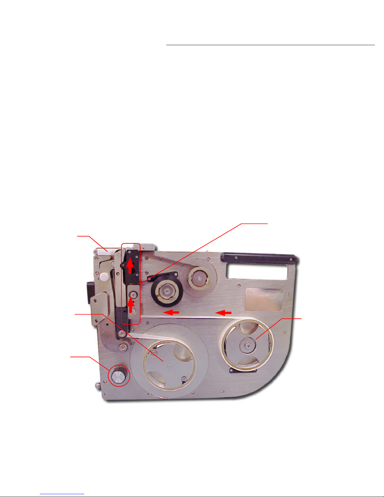
To install a label media reel, set the drive arm ‘lock knob’ to the ‘open’ position (see section 4.2
Take the label leader and feed it between the ‘transfer roller arm’ assembly and the label tension
Operations
4.3 Installing the Label Media Reels
of this chapter for instructions) and snap the pressure clips on the ‘stock’ and ‘take up’ label
mandrels to the open position.
Place an empty core onto the ‘take up’ mandrel and snap the pressure clips on the mandrel to
the ‘closed’ position to secure the reel to the mandrel.
Place the label media reel onto the ‘stock’ mandrel so that it feeds from the top of the reel and
then snap the pressure clips on this mandrel to the ‘closed’ position to secure the reel to the
mandrel.
block and print head cover as shown in diagram 4.3a.
Label deck
Take up
mandrel
Manual
advance
knob
Feed label leader
between these parts
Stock
mandrel
Diagram 4.3a
29
Page 36
PL1200 Thermal Transfer Printer
diagram 4.3b
The label media reel is now installed and ready for operation.
Operations
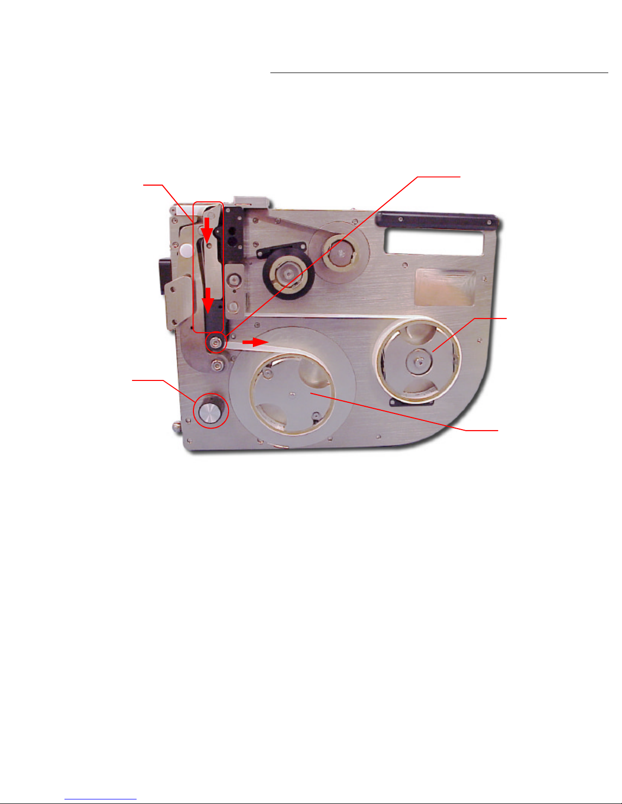
Lift the ‘label deck’ and run the label leader over the roller at the top of the ‘transfer roller arm’
and bring it down between the ‘transfer roller arm’ and the ‘drive arm’ assembly as shown in
Feed label
leader between
these two parts
Manual
advance
knob
Roller guide
Stock
mandrel
Take up
mandrel
Diagram 4.3b
Next, feed the leader along the guide roller at the base of the ‘transfer roller arm’ and onto the
core reel on the ‘take up’ mandrel. Use a label to secure the label leader to the core reel.
By turning the label advance knob clockwise, the label leader will wind onto the ‘take up’
mandrel. Spin it a few time to check that the label leader is secured to the core reel.
30
Page 37

PL1200 Thermal Transfer Printer
To remove the label media reels from the mandrels, place the drive arm ’lock knob’ to the open
ition. If the label stock is empty remove the core, and then remove the
If the stock label reel still has material on it, simply tear the tape material near the stock reel and
To install the thermal transfer media reel, set the drive arm ‘ lock knob’ to the open position (see
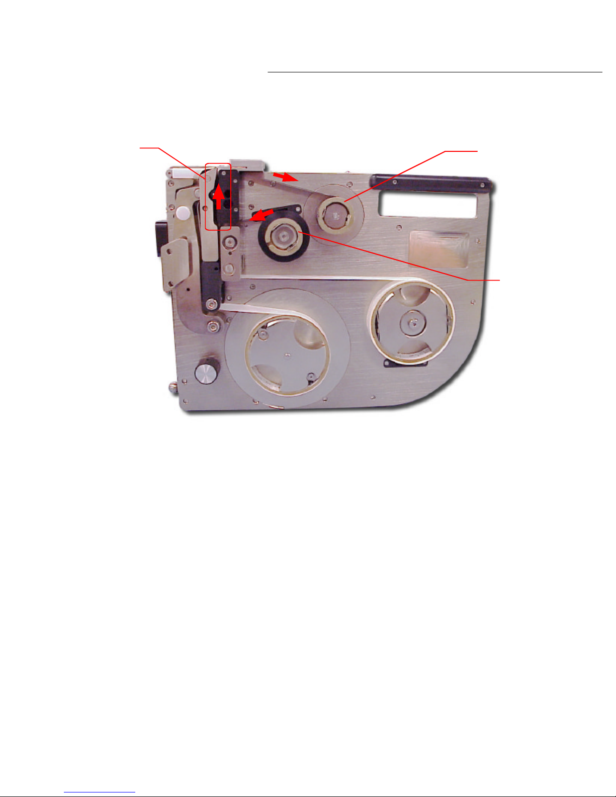
Place the thermal transfer media reel onto the ‘stock’ mandrel so that it feeds from the top of the
this mandrel to the ‘closed’ position to secure the reel to
Take the thermal transfer tape leader and feed it be
Operations
4.4 Removing the Label Media Reels
position (see section 4.2 of this chapter) and snap the pressure clips on the ‘stock’ and ‘take up’
mandrels to the open pos
used tape material and core from the take up mandrel.
then spin the manual advance knob clockwise until all the remaining tape material is wound onto
the take up reel.
Both reels may now be removed from the mandrels. Save all empty stock cores for later use on
the take up mandrels.
4.5 Installing the Thermal Transfer Media Reels
section 4.2 of this chapter for instructions) and snap the pressure clips to the ‘closed’ position to
secure the reel to the mandrel.
Place an empty core on the ‘take up’ mandrel and snap the pressure clips to the ‘closed’ position
to secure the reel to the mandrel.
reel and then snap the pressure clips on
the mandrel. Please note that the media reel must be loaded correctly for the thermal transfer
medium to apply properly to the label surface.
tween ‘print head cover’ and ‘label tension
block’ then feed it upwards between ‘print head cover’ and ‘transfer roller arm’ as shown in
diagram 4.5a.
31
Page 38
PL1200 Thermal Transfer Printer
Operations
Feed the
tape between
these two parts
Take up
mandrel
Stock
mandrel
Diagram 4.5a
Next, feed the tape up and over the ‘print head cover’ and onto the ‘take up’ mandrels shown in
diagram 4.5a.
Now place the tape onto the ‘take up’ reel and secure it with a label.
By manually spinning the ‘take up’ mandrel clockwise, the tape will wind onto the reel. Spin it a
few times to check that the tape is secured to the core reel.
32
Page 39

PL1200 Thermal Transfer Printer
The thermal transfer print reel is now installed and ready for operation.
To remove the thermal transfer media reels place the drive arm ‘lock knob’ to the open position
rels
stock reel and the spin the manual advance knob clockwise until all the remaining ribbon material
When the PL1200 is mounted to the docking station it will power up. At power up the calibration
Operations
Please note: Due to the stiff leader that normally comes with a new ribbon, threading thought
the print head is easy to facilitate. Occasionally, prior to running out of ribbon, it may be
necessary to remove the ribbon from the labeler. When threading it back on the labeler you may
find the ribbon tends to twist in the absence of the stiff leader. To resolve this simply advance
the take up reel, and as the tape tightens it should straighten out.
4.6 Removing the Thermal Transfer Media Reels
(see section 4.2 of this chapter) and snap the pressure clips on the ‘stock’ and ‘take up’ mand
to the open position. If the thermal transfer stock reel is empty remove the core, and then
remove the used print tape material and core from the take up mandrel.
If the stock thermal transfer reel still has material on it, simply cut the ribbon material near the
is wound onto the take up reel.
Both reels may now be removed from the mandrels. Save all empty stock cores for use on the
take up mandrels.
4.7 About the Calibration Sequence
LED flashes on the ’CAL’ switch indicating that the operator needs to perform a label calibration
sequence before labeling can begin. It is important to complete this operation.
33
Page 40

PL1200 Thermal Transfer Printer
To translate what is seen on the computer screen into what will print on the label, the rulers that
The vertical phantom edge of the label on the computer screen represents the leading edge of
Operations
Calibration is required and must be performed any time one of the following occurs; the drive
arm has been opened and the label or print media reels have been changed, the PL1200 labeling
unit has been mounted or removed from the docking station causing a power off/on sequence,
when a calibration, label alignment or tape out error has occurred (please refer to Chapter 2 –
Sections 2.8 and 2.9 for detailed information regarding these conditions).
Any of these conditions will alert the operator by flashing the ‘CAL’ switch LED. Once a
calibration sequence has been done, printing can commence.
4.8 About Labels Positioning Logic
Positioning of the label in relation to the print head is achieved by knowing the number of motor
steps between the print head and the label detect sensor. As the leading edge of each label
passes the optic, its position is recorded. The label position is then determined as the distance
from the label detect sensor to the print head plus the presentation offset.
When a print operation begins, the distance of the closest label to the print head is used as the
advance distance. Label positions are recorded as motor steps. This is transparent to the user.
4.9 About Labels and Printing
Before you edit or create a label there are a few things to keep in mind. It is always
recommended whenever editing existing or creating new labels that the computers screen be
maximized so that all of the label and its text can be seen.
It is important to understand that the label text displayed on the computer screen, while it may
fit into the label displayed on the computer screen, may not actually fit onto the physical label
itself. The software, which displays the label on the screen, is unaware of the physical
dimensions of the label media to be printed on.
border the label on the computer screen should be used when picking and placing text on the
screen. These rulers can be set in inches or millimeters, depending on the user needs. The
rulers are to be used as a reference or guideline only.
the label and should be used as a guideline for text placement in relation to the leading edge of
the label to be printed. The top and bottom phantom lines should be used to center the text
vertically on the actual label to be printed.
Please refer to the Brother P-Touch Editor users guide for further information.
34
Page 41

Maintenance
5
Page 42
PL1200 Thermal Transfer Printer
Maintenance
Chapter 5: Maintenance
The PL1200 labeling system requires very simple maintenance to keep it running smoothly.
Please follow the instruction below.
5.1 Rollers
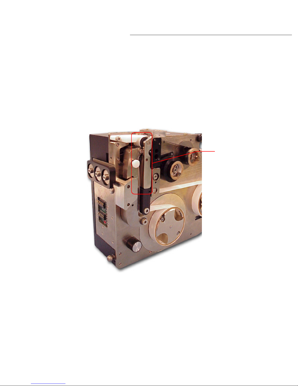
It is important to keep the rollers on the PL1200 clean at all times. The Roller locations are
shown in diagram 5.1a.
There are rollers
located in these
areas
Occasionally, if a label is not picked off the label deck properly, the label can get stuck on the
rollers just below the label deck. Should this occur, remove the label from the roller.
Additionally, at this time and periodically, wipe the rollers clean with alcohol.
5.2 PL1200 Labeling Unit
It is recommended that the PL1200 labeling unit be cleaned with compressed air on a as needed
basis to remove any dust and paper debris that may have accumulated. This should also be
done with all media reels removed from the unit.
Diagram 5.1a
35
Page 43

36
Page 44

Troubleshooting
6
Page 45

PL1200 Thermal Transfer Printer
This chapter will describe problems, which may occur during operation of the PL1200 labeling
Troubleshooting
Chapter 6: Troubleshooting
system and the information needed for diagnosing and correcting these problems.
6.1 Print Smudging
Should you experience print smudging on the labels make sure that all rollers are clean. Any
debris should be removed and the rollers should be cleaned with alcohol.
If the problems persist, the slip clutch tension may need to be adjusted. The slip clutch
tension is the pulley that advances the ‘take up’ mandrels.
To adjust the slip clutch tension, remove the labeler from the docking station. Next, remove
the cover of the PL1200 labeling unit. Spin the manual advance knob to advance the labels
and check the label dispensed for smudging.
If smudging is present, loosen the clutch by turning the knob counter clockwise, a few clicks
at a time, until mandrels spin with little or no resistance and smudging is resolved. Return
the labeler to the docking station.
WARNING
6.2 Inconsistent Print Length
Should you experience inconsistent print length or the print varies from label to label, make
sure all rollers are clean. Any debris should be removed from the rollers and the rollers
should be cleaned with alcohol.
If the problem persists, manually spin the label ‘stock’ mandrel (please refer to photo 4.3b in
Chapter 4). If this produces inconsistent drag on the labels being dispensed, the slip clutch
tension on the label take up mandrel may need to be adjusted.
WARNING : POSSIBLE PINCH POINTS KEEP HANDS CLEAR.
37
Page 46
PL1200 Thermal Transfer Printer
To adjust the slip clutch tension, remove the labeler from the docking station. Next, remove the
assemble the mandrel, and then
To do so, remove the cover from the PL1200 labeling unit. Spin the manual advance knob
This problem can occur if
Troubleshooting
cover of the PL1200 labeling unit. Spin the manual advance knob to advance the labels and
check the label dispensed for smudging.
If there is no galling present, clean and grease the mandrel. Rerecheck the problem. If it still persists, please consult the factory.
If the ‘Calibration’ light starts to flash after a few labels have been printed and the rollers are
clean, it is recommended that the slip clutch tension be tightened on the label take up mandrel.
clockwise to tighten.
WARNING
6.3 Labels Won’t Calibrate
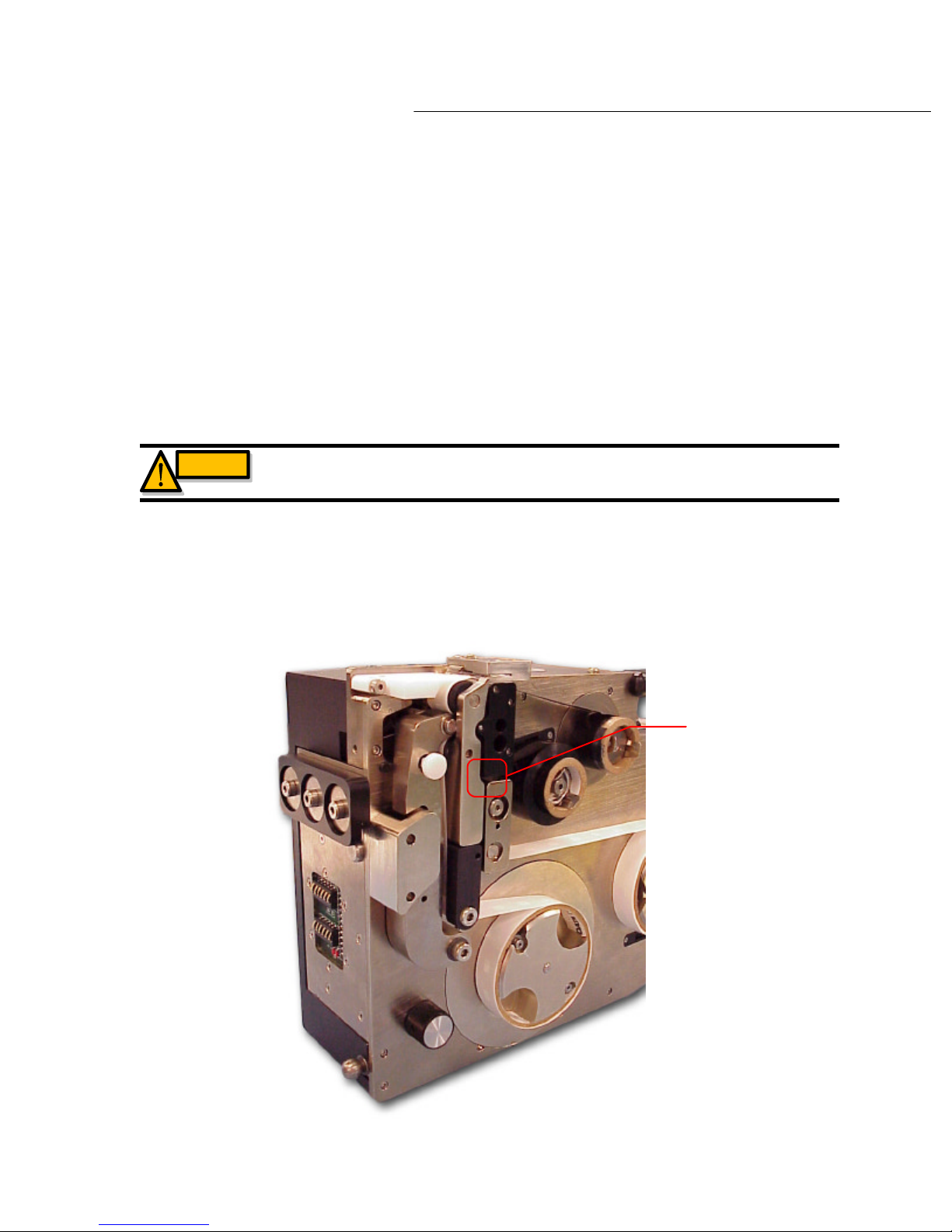
Identco brand labels. This sensor is located between the ‘label tension block’ and the ‘transfer
roller arm’ as shown in diagram 6.3a
WARNING : POSSIBLE PINCH POINTS KEEP HANDS CLEAR.
the ‘label alignment ‘ sensor needs to be adjusted or you are not using
Diagram 6.3a
Label alignment
sensor location
38
Page 47
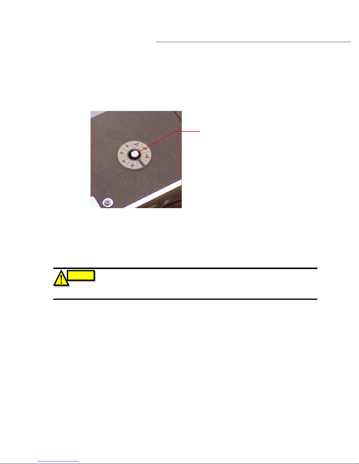
To adjust this sensor, use a screwdriver to turn the potentiometer located on top of the laberer.
(see diagram 6.3b).
PL1200 Thermal Transfer Printer
Troubleshooting
Potentiometer
Diagram 6.3b
By placing the screwdriver in the slot and turning this will adjust the potentiometer.
CAUTION
Spin the screw a 1/16 of a turn. Now depress the ‘CALIBRATION’ switch. Check to see if the
calibration sequence occurs. If the calibration sequence does not occur repeat the above
instructions until the desired calibration sequence is obtained.
If the calibrate sequence does occur, press the ‘CALIBRATION’ switch multiple times, each time
checking to ensure the consistency of the label dispense sequence.
Once the desired consistency is achieved, you may now resume operations as normal.
Please note, this potentiometer is a ten turn POT, and is VERY SENSITIVE. A ¼
turn can have a dramatic effect on the adjustment on this POT. It is therefore
recommended that you turn this adjustment screw no more than 1/16 of a turn
AT ANY ONE TIME!
39
Page 48

PL1200 Thermal Transfer Printer
To test the label stock reel and thermal print stock reel sensor remove the stock reels from the
mandrels. Place your finger over the sensors. When the sensor is blocked, the error indicator on
Next, check the contacts on the docking station. If there is dirt or debris, clean the contacts with
Troubleshooting
6.4 Testing Stock Reel Low Sensors
the switch bank should not illuminate. Remove your finder from the sensor. The error indictor
should now illuminate. Test both sensors to ensure that they are operating correctly.
6.5 Communication Problems
Check to ensure all cables, both serial and parallel between your PC and PL1200 labeling unit are
connected correctly and are stable.
alcohol or any appropriate contact cleaner. Should any damage to the contacts be found, please
contact the factory for replacement information.
6.6 No Power to the PL1200 when Docked
Check the power plug in the wall outlet as well as the power connector to the PL1200 labeling
unit. After checking power to the docking station, make sure that the labeler is docked and
seated correctly.
CAUTION
Use caution when checking for power. Live exposed wires can cause shock
And electrocution.
40
Page 49

Schematic
-and-
Wiring
7
Page 50
41
PL1200 Thermal Transfer Printer
Schematic and Wiring
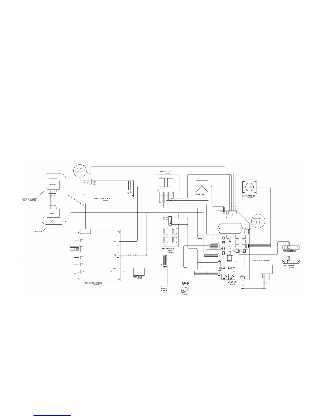
Chapter 7: Schematic and Wiring
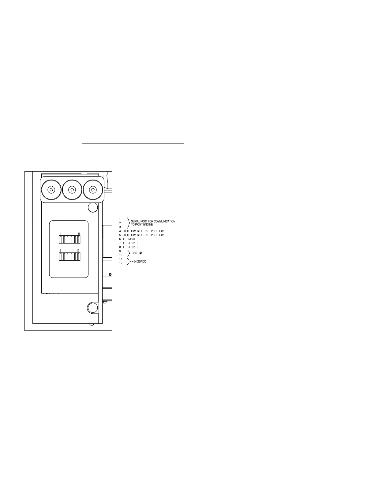
On the following pages you will find the Schematic and Wiring diagrams for the PL1200
labeling system.
42
Page 51
43
PL1200 Thermal Transfer Printer
Schematic and Wiring
44
Page 52

Spare Parts,
Decommissioning,
-and-
Product Specifications
8
Page 53

PL1200 Thermal Transfer Printer
Spare Parts, Decommissioning,
and Product Specifications
Chapter 8: Spare Parts, Decommissioning, and Product Specifications
This chapter contains a recommended spares kit and decommissioning information.
8.1 Recommended Spares Kit
•
Anti-static brush – 1 each
•
2.5 amp fuse – 2 each
•
Print head unit – 1 each
•
Labels – See Identco label specs for ordering
•
Thermal transfer print ribbon – see Identco ribbon specs for ordering
•
Pressure clips (2 pairs) 1 pair for label mandrels, 1 pair for Print ribbon mandrels
•
Custom pin-out interconnect cable – 1 each
•
28 volt 1.5 amp AC power adapter – 1 each
8.2 Decommissioning
When decommissioning the PL1200 labeling system, place it in its original packaging and
return to the manufacturer, Hover-Davis, Inc.
45
Page 54

PL1200 Thermal Transfer Printer
8.3 Product Specifications
Spare Parts, Decommissioning,
and Product Specifications
Environmental Requirements:
Storage temperature should be in the range of 33 degrees F to 120 degrees F.
Operational temperatures should remain within the range of 60 degrees F to 200 degrees F.
Humidity should not exceed 75% RH, with no condensation
Power Requirements:
24 Volts at 1.5 amps for the labeling unit.
120 Volts at 60 hertz at 1 amp for the power supply module
The PL1200 dimension;
Length: 13.12 inches
Width: 4.88 inches
Height: 9.75 inches
Weight: 10.75 pounds
Label Specifications:
Linear Width: 0.695 inches
Minimum Label Width: 0.10 inches
Maximum Label Width: 0.60 inches
Minimum Label Length: 0.125*
Maximum Label Length: 1.50 inches
Label Spacing: .500 inches between labels
*For shorter label lengths, please consult factory.
46
Page 55

Technical
Bulletins
9
Page 56

PL1200 Thermal Transfer Printer
Technical Bulletins
Chapter 9: Technical Bulletins
This chapter is for any technical bulletins that the factory may issue for the PL1200. Please
place all technical bulletins that are issued for the PL1200 from the factory in this section of
the manual. This will ensure that the most current and up to date information for this
product as it relates to the manual and or actual product has been noted.
47
Page 57

48
 Loading...