

Hoval UltraGas 150, UltraGas 400, UltraGas 200, UltraGas 250, UltraGas 300 Installation Instructions Manual
...
Subject to modi cations |
EN
Technical information
Installation instructions
4 213 783 / 00 - 06/15
Hoval products may only be installed and commissioned
by appropriately qualied experts. These instructions
are intended exclusively for the specialist. Electrical
installations may only be carried out by a qualied
electrician.
Vertical gas condensing boilers UltraGas® (125-1000)
acc. to EN 483 and EN 677 are suitable and licensed for
use as heat generators for hot water heating systems
with a permissible ow temperature of up to 90 °C1).
They are designed for continuously controlled reduced
operation in a heating system.
1)
See technical data
UltraGas® (125 - 1000)
Condensing gas boilers
for natural gas and liqueed gas
for modulating operation
These instructions are applicable to the
following types:
Nominal output ranges at 40/30°C and
with natural gas
41-UltraGas® (125) 28 - 123 kW
41-UltraGas® (150) 28 - 150 kW
41-UltraGas® (200) 44 - 200 kW
41-UltraGas® (250) 49 - 250 kW
41-UltraGas® (300) 57 - 300 kW
41-UltraGas® (350) 58 - 350 kW
41-UltraGas® (400) 97 - 400 kW
41-UltraGas® (450) 97 - 450 kW
41-UltraGas® (500) 97 - 500 kW
41-UltraGas® (575) 136 - 575 kW
41-UltraGas® (650) 136 - 650 kW
41-UltraGas® (720) 142 - 720 kW
41-UltraGas® (850) 166 - 850 kW
41-UltraGas® (1000) 224 - 1000 kW
41-UltraGas® H (720) 142 - 720 kW
41-UltraGas® H (1000) 224 - 1000 kW

2
4 213 783 / 00
TABLE OF CONTENTS
1. Important notes
1.1 General safety instructions .................................................................................................................................................4
1.2 Explanation of the symbols ................................................................................................................................................4
1.2.1 Warnings ..........................................................................................................................................................................4
1.2.2 Icons .................................................................................................................................................................................4
1.3 On delivery ...........................................................................................................................................................................5
1.4 Warranty ...............................................................................................................................................................................5
1.5 Manuals ................................................................................................................................................................................5
1.6 Regulations, official approvals ...........................................................................................................................................6
1.6.1 Germany § ........................................................................................................................................................................6
1.6.2 Austria § ...........................................................................................................................................................................6
1.6.3 Switzerland § ....................................................................................................................................................................6
2. Installation
2.1 Set-up ...................................................................................................................................................................................7
2.2 Fitting the thermal insulation ............................................................................................................................................10
2.3 Fitting the casing ............................................................................................................................................................... 11
2.4 Fitting the pedestal casing ................................................................................................................................................14
3. Technical information
3.1 Description of the boiler ...................................................................................................................................................16
3.2 UltraGas® (125-300) technical data ...................................................................................................................................17
3.3 Dimensions space / required ............................................................................................................................................20
3.3.1 Overall unit dimensions ...................................................................................................................................................21
3.4 Boiler flow resistance ........................................................................................................................................................22
3.5 Brief description of the automatic firing device ...............................................................................................................23
4. Installation
4.1 Safety instructions ............................................................................................................................................................24
4.2 Requirements on the boilerhouse ....................................................................................................................................24
4.2.1 Room air dependent installation ......................................................................................................................................24
4.2.2 Room air independent installation ...................................................................................................................................24
4.3 Flue gas connection, flue gas conduit .............................................................................................................................25
4.4 Condensate drain ..............................................................................................................................................................25
4.4.1 Design variants ...............................................................................................................................................................25
4.5 Gas connection ..................................................................................................................................................................26
4.6 Hydraulic connection ........................................................................................................................................................26
4.6.1 To be provided on-site ..................................................................................................................................................... 27
4.6.2 Hydraulic integration .......................................................................................................................................................27
4.6.2.1 Cascades .......................................................................................................................................................................................27
4.7 Electrical connection .........................................................................................................................................................28
5. Commissioning
5.1 Safety instructions ............................................................................................................................................................29
5.2 Filling the heating system .................................................................................................................................................29
5.3 Water quality ......................................................................................................................................................................30
5.4 Venting the gas pipe ..........................................................................................................................................................31
5.5 Switch on ...........................................................................................................................................................................31
5.6 Gas inlet pressure .............................................................................................................................................................31
5.7 Setting the gas quantity, measuring the CO2 (O2) and NOx/CO content in the flue gas .................................................32
5.7.1 UltraGas® (125-720) flue gas measurement ....................................................................................................................32
5.7.2 UltraGas® (850, 1000) flue gas measurement ..................................................................................................................32
5.8 Changing to a different type of gas ..................................................................................................................................33
5.9 Type (850, 1000) setting the stabilisation damper (if required) .......................................................................................35
5.10 Handover to the operator ..................................................................................................................................................35
5.11 Activation of screed function ............................................................................................................................................36

3
4 213 783 / 00
TABLE OF CONTENTS
6. Maintenance
6.1 Safety instructions ............................................................................................................................................................38
6.2 Deaeration ..........................................................................................................................................................................38
6.3 Top up with water ..............................................................................................................................................................38
6.4 Renewing fuse ...................................................................................................................................................................38
6.5 Information for fire inspector / chimney sweep regarding emission and manual operation settings ...........................39
6.6 Cleaning .............................................................................................................................................................................40
6.6.1 Cleaning the burner cylinder (inside and out) ..................................................................................................................40
6.6.2 Cleaning the combustion chamber and burner cylinder on the outside .............................................................................41
6.6.3 Clean/adjust ignition and ionisation devices ....................................................................................................................42
6.6.4 Cleaning the gas filter HFVR050 (only applicable for UltraGas® (450-720)) (if fitted) .......................................................43
6.7 Setting the gas quantity, measuring the CO2 (O2) and NOx/CO content in the flue gas .................................................44
6.8 Cleaning the condensation trap ........................................................................................................................................44
6.9 Maintaining the neutralisation unit for type 23 and type 24 (if fitted) .............................................................................45
4
4 213 783 / 00
IMPORTANT NOTES
1. Important notes
1.1 General safety instructions
The system may only be placed in operation
if all the relevant standards and safety regula
-
tions have been complied with.
At least the following conditions must be satised for a trial operation:
- Safety valve installed (system sealed)
- Control system in operation (connected to the power
supply)
- Sensor for safety temperature limiter connected (= boiler temperature sensor)
- System lled with water
- Condensation trap lled with water
- Expansion tank connected
- Flue gas outlet with ue gas conduit connected to ue
gas system.
- Burner preset (see point 6.7).
WARNING
The heat generator can only be de-energised
by disconnection from the mains (e.g. allpole switch).
WARNING
All electric power supply circuits must be
switched off before accessing the terminals.
1.2 Explanation of the symbols
1.2.1 Warnings
!
DANGER
... indicates a situation of immediate danger
which will lead to serious or fatal injuries if
not avoided.
!
WARNING
... indicates a situation of possible danger
which can lead to serious or fatal injuries if
not avoided.
!
CAUTION
... indicates a situation of possible danger
which can lead to minor or slight injuries if
not avoided.
NOTICE
... indicates a situation of possible danger
which can lead to damage to property if not
avoided.
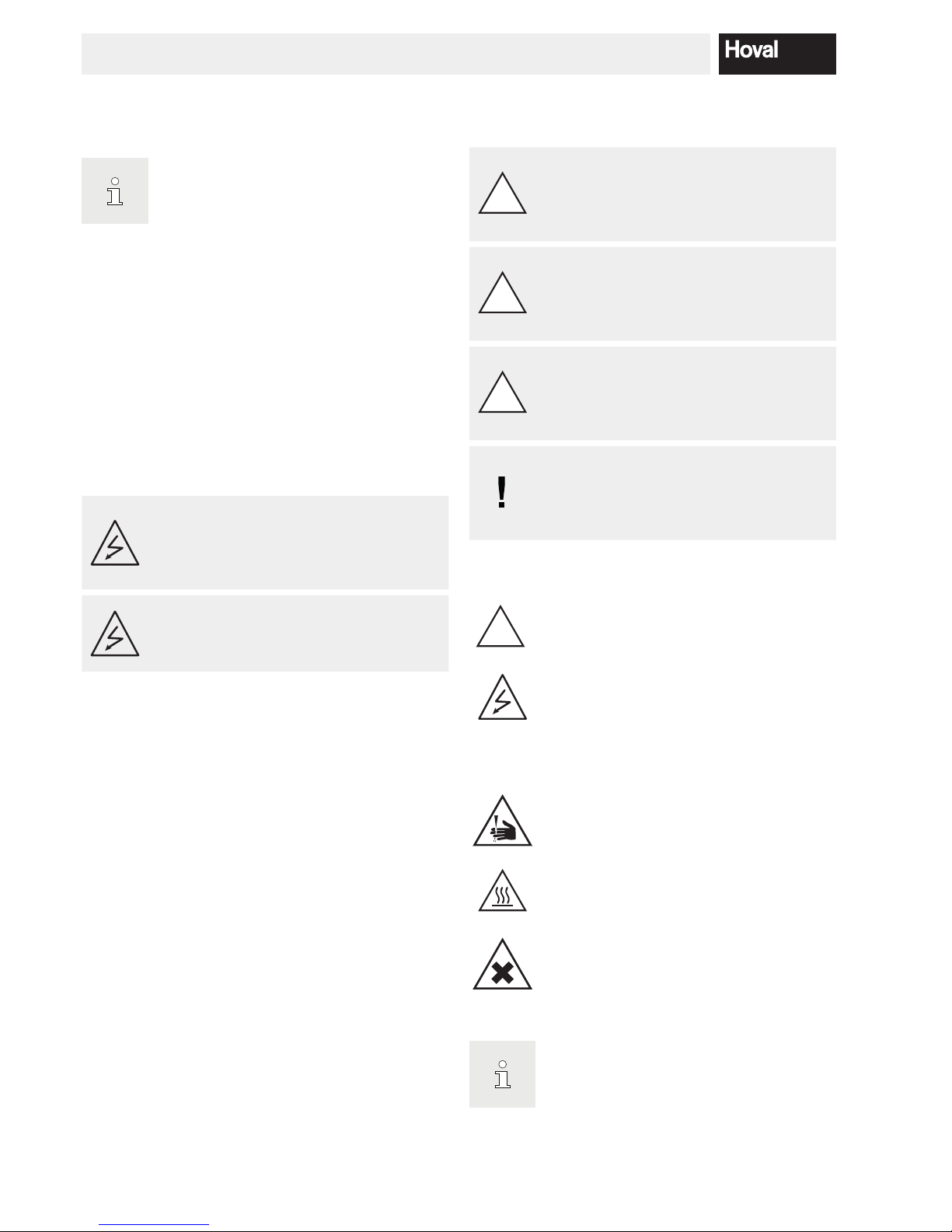
1.2.2 Icons
!
General warning of a danger zone.
"Warning: dangerous electrical voltage" as
a warning for accident prevention.
Ensures that people do not come into contact
with electrical voltage. The danger sign with
the black lighting symbol warns against the
danger of electrical voltage.
Warning of cutting injuries.
Warning of hot surface
Indicates dangers of injury and burns on hot
surfaces.
Danger: Substances with a corrosive effect on
skin, eyes and respiratory organs; can cause
irritation.
Handling: Do not inhale vapours and avoid
contact with skin and eyes.
Information:
Provides important information.

5
4 213 783 / 00
IMPORTANT NOTES
Follow the instructions for use.
Requirements to comply with the instructions.
Information:
Which tools and other equipment are required.
§
Provides important information.
Refers to standards and directives.
1.3 On delivery
Carry out a visual inspection immediately on receiving the
boiler. If any damage is found, take the necessary steps
as dened in the delivery contract. The respective risk
carrier bears the cost of repairs.
1.4 Warranty
The warranty does not cover defects attributable to:
• Failure to comply with these instructions
• Failure to comply with the operating instructions
• Incorrect installation
• Impermissible modications
• Incorrect handling
• Contaminated operating materials (gas, water, combustion air)
• Unsuitable chemical additives to the heating water
• Damage caused by the application of force
• Corrosion by halogen compounds (e.g. paints, adhesives, solvents)
• Corrosion caused by not observing the required water
quality
1.5 Manuals
All instructions relevant to your system can be found in
the Hoval system manual! In exceptional cases, the instructions can be found with the components!
Further sources of information:
• Hoval catalogue
• Standards, regulations

6
4 213 783 / 00
IMPORTANT NOTES
1.6 Regulations, official approvals
The standards and directives stated under points 1.6.1 to
1.6.3 must be taken into account during installation and
operation of the system.
1.6.1 Germany §
- DIN EN 12831 Heating systems in buildings – Method
for calculation of the design heat load
- DIN EN 13384 Flue gas systems – Calculation methods
in heat and ow engineering
- DIN EN 12828 Heating systems in buildings - Design of
hot water systems.
- DIN 4755 Oil-red systems. Design, construction and
safety engineering requirements.
- DIN 4756 Gas-red combustion systems: design, construction and safety engineering requirements, design
and construction (for operation with gas burners).
- DIN 18160 House chimneys; requirements, planning
and execution.
- TRD 702 Steam boiler plants with caloriers of the
group II.
- TRD 721 Safety devices against excess pressures /
safety valves / for steam boilers of Group II.
- VDI 2035 Prevention of damage by corrosion and the
formation of scale in hot water heating systems.
- DIN 57 116 / VDI 0116 Electrical equipment for ring
systems (VDE Regulation).
- For further standards applicable in Germany, see appendix N-430 020.
1.6.2 Austria §
- OENORM 12831 Heating systems in buildings - Procedure for calculation of the standard heating load
- OENORM 13384 Waste gas systems – Procedures for
heat and ow calculations
- OENORM 12828 Heating systems in buildings - Design
of hot water systems.
- ÖNorm B 8130 Open water heating systems; safety devices.
- Norm B 8131 Closed water heating systems; safety, execution and testing requirements.
- ÖNorm B 8133 Hot water production systems; technical
safety requirements.
- ÖNorm B 8136 Heating systems, space requirements
and other building requirements.
- ÖNorm M 7515 Calculations of dimensions of chimneys; terminology, calculation procedure.
- ÖNorm H 5171 Heating systems – construction engineering requirements.
- ÖVGW TR-gas (Austrian Gas and Water Confederation
- Technical Guidelines)
1.6.3 Switzerland §
- SN EN 12831 Heating systems in buildings - Procedure
for calculation of the standard heating load
- SN EN 13384 Flue gas systems - Heat and ow calculation methods
- SN EN 12828 Heating systems in buildings - Design of
hot water heating systems.
- VKF – Association of Cantonal Fire Insurers.
- Fire prevention authority regulations.
- SVGW Swiss Association for Gas and Water.
- SNV 27 10 20 Aeration and ventilation of the boiler installation room.
- SWKI BT102-01 Water quality for building services systems.
- Technical tank regulations TTV 1990.
- EKAS - Guidelines for liqueed gas Part 2
and further regulations and standards issued by CEN,
CEN ELEC, DIN, VDE, DVGW, TRD and the legislative
body. The regulations of the local building authorities, insurance companies and chimney sweeps must also be
taken into account. The regulations of the responsible
gas supply company are to be complied with if using gas.
Approval by the authorities may be required.
7
4 213 783 / 00
INSTALLATION
2. Installation
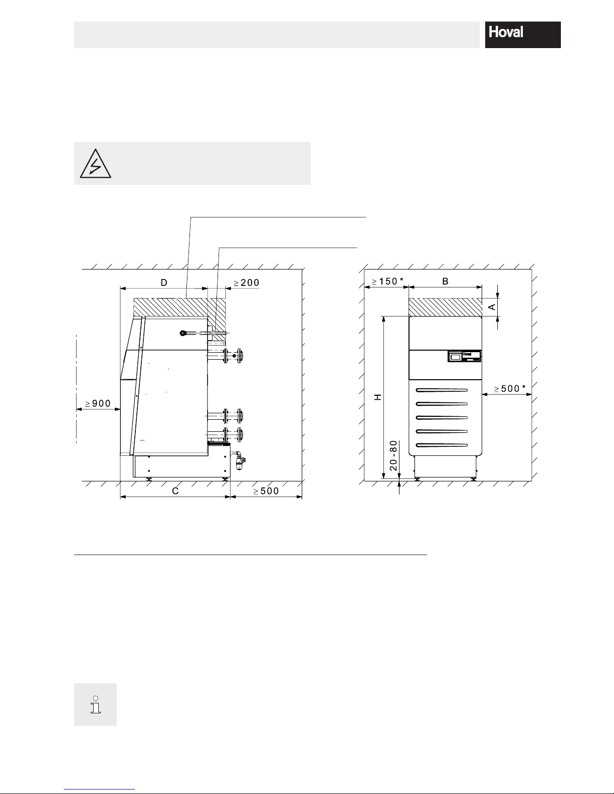
2.1 Set-up
Space requirement of UltraGas® (125-1000)
(All dimensions in mm)
CAUTION
The cables must not touch any hot parts.
Straight gas connection line route
to the rear
For swinging out the burner this area
must remain free
Fig. 01
UltraGas
®
Model
A A mini-
mum
B C D H H mini-
mum
(125, 150) 180
1
80
2
820 1237 981 1823 1711
3
(200 - 300) 360 1160
2
930 1584 1247 1923 1811
3
(350 - 500) 200 1100
2
1110 1679 1268 2070 1958
3
(575 - 720) / H (720) 200 1100 21290 1843 1438 2086 1984
3
(850, 1000) / H (1000) 420 1230 21550 2154 1703 2139 2037
3
1
If the room height is too low: the dimension can be reduced. See A
minimum.
2
Caution! At A minimum, the burner can no longer be swivelled out
completely! Cleaning is made difcult!
3
Feet can be shortened, no pedestal casing possible! For details see
next page.
The boiler can be placed with one side directly
the wall. For the casing to be installed, how
-
ever, there must be a distance of at least 100
mm from the wall.
8
4 213 783 / 00
INSTALLATION
cut off
UltraGas
®
(575 - 1000)
UltraGas
®
(575 - 1000)
UltraGas® with shortened boiler feet
(All dimensions in mm)
UltraGas® peak load boiler
Model A
(125, 150) 1723 - 1783
(200 - 300) 1823 - 1883
(350 - 500) 1970 - 2030
(575 - 720) / H (720)
1986 - 2046
(850, 1000) / H (1000)
2039 - 2099
UltraGas® peak load boiler
Model A
(125, 150) 1711 - 1771
(200 - 300) 1811 - 1871
(350 - 500) 1958 - 2018
(575 - 720) / H (720)
1984 - 2044
(850, 1000) / H (1000)
2037 - 2097
UltraGas® peak load boiler
Model A
(125, 150) 1721
(200 - 300) 1821
(350 - 500) 1968
(575 - 720) / H (720)
1994
(850, 1000) / H (1000)
2047
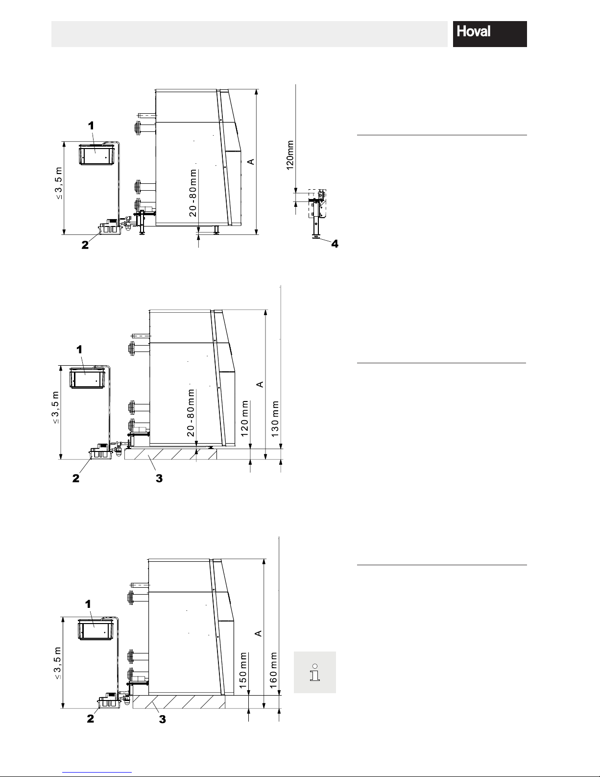
UltraGas
®
with walled-in pedestal and adjustable feet
UltraGas
®
with walled-in pedestal without adjustable feet
1 Neutraliser box
2 Condensate pump
3 Walled base
4 Adjustable feet 20-80 mm
No refunds for pedestal sheets and adjusting
feet!
9
4 213 783 / 00
INSTALLATION
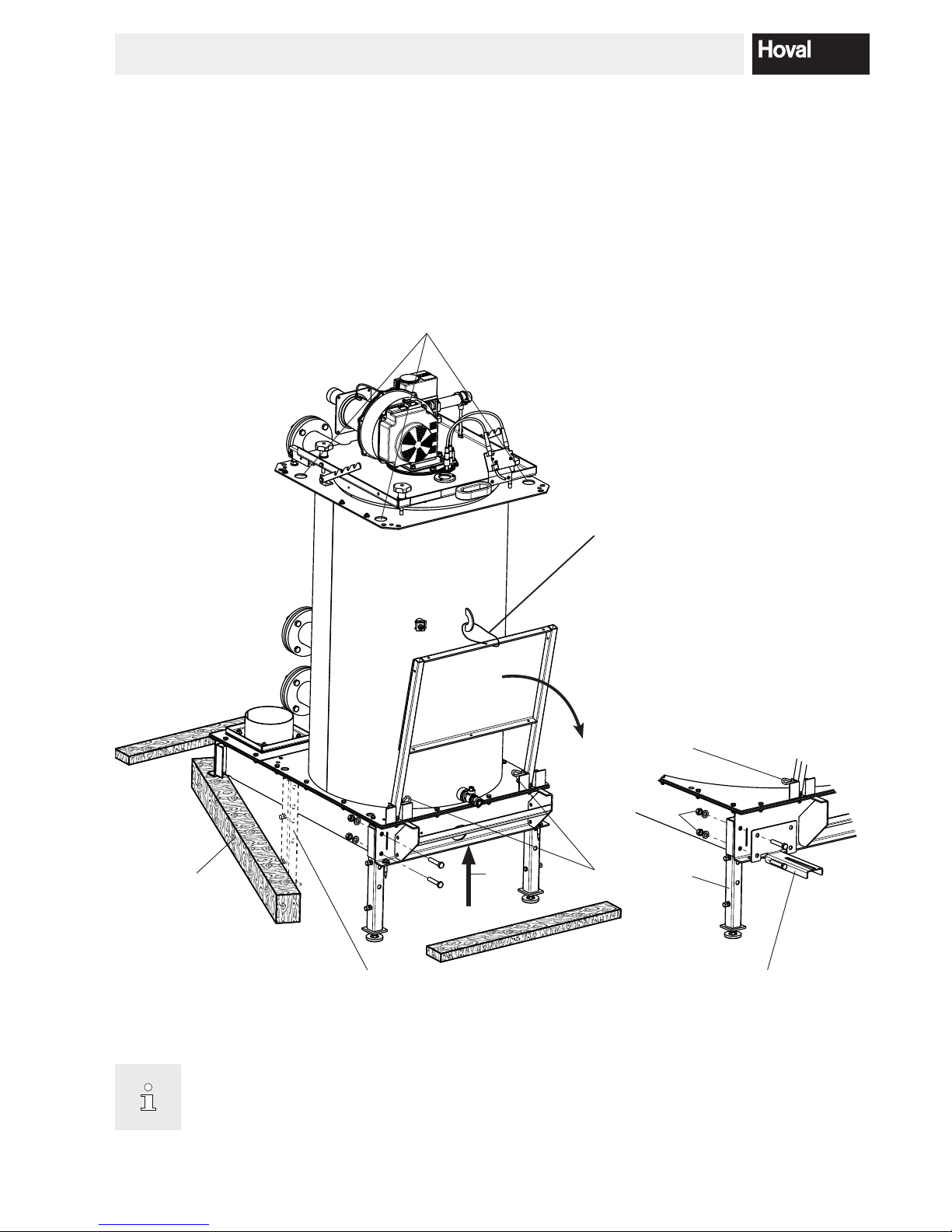
Procedure:
1. Remove the top two screw connections (1, Fig. 02) on the boiler foot (1a, Fig. 02).
2. Remove front wooden crossbeam.
3. Using a winch (3, Fig. 02) raise the front of the boiler.
4. Take out the side beam (4, Fig. 02) at the front to the side (see Fig. 02).
5. Push in the front feet and screw on.
6. Using a winch (3, Fig. 02, Fig. 02) raise the rear of the boiler.
7. Take out the side beam (4, Fig. 02) at the rear to the side (see Fig. 02).
8. Push in the rear feet and screw on.
9. Remove the step board protection (5, Fig. 02). Remove the securing pins (6, Fig. 02) and carefully fold the step
board down. In types (850, 1000) fold up 2nd and 3rd step board or remove ladder.
4 1a
1
3
Types (850, 1000) (H (720, 1000))
with six feet
6
5
Types (575-1000) (H (720, 1000))
Suspension possibilities for crane
1b
Fig. 02
Adjustable foot height is set after installation
of the neutralisation unit.
10
4 213 783 / 00
INSTALLATION
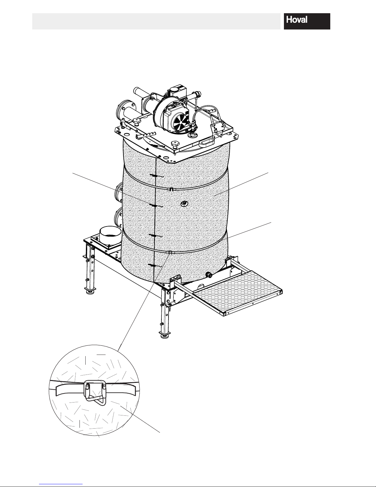
2.2 Fitting the thermal insulation
Place the insulation mat (1, Fig. 03) around the UltraGas® boiler and attach with plastic straps (1a, Fig. 03) and strap
fasteners (1b, Fig. 03).
- Tension springs (1c, Fig. 03) serve for additional xing
- Do not overtighten the straps (reduced insulating value).
1
1a
1b
Fig. 03
1c
11
4 213 783 / 00
INSTALLATION
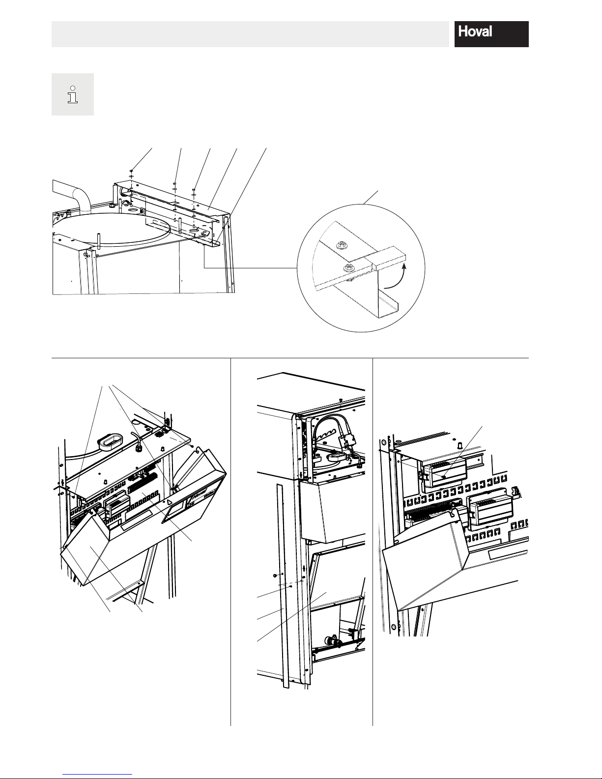
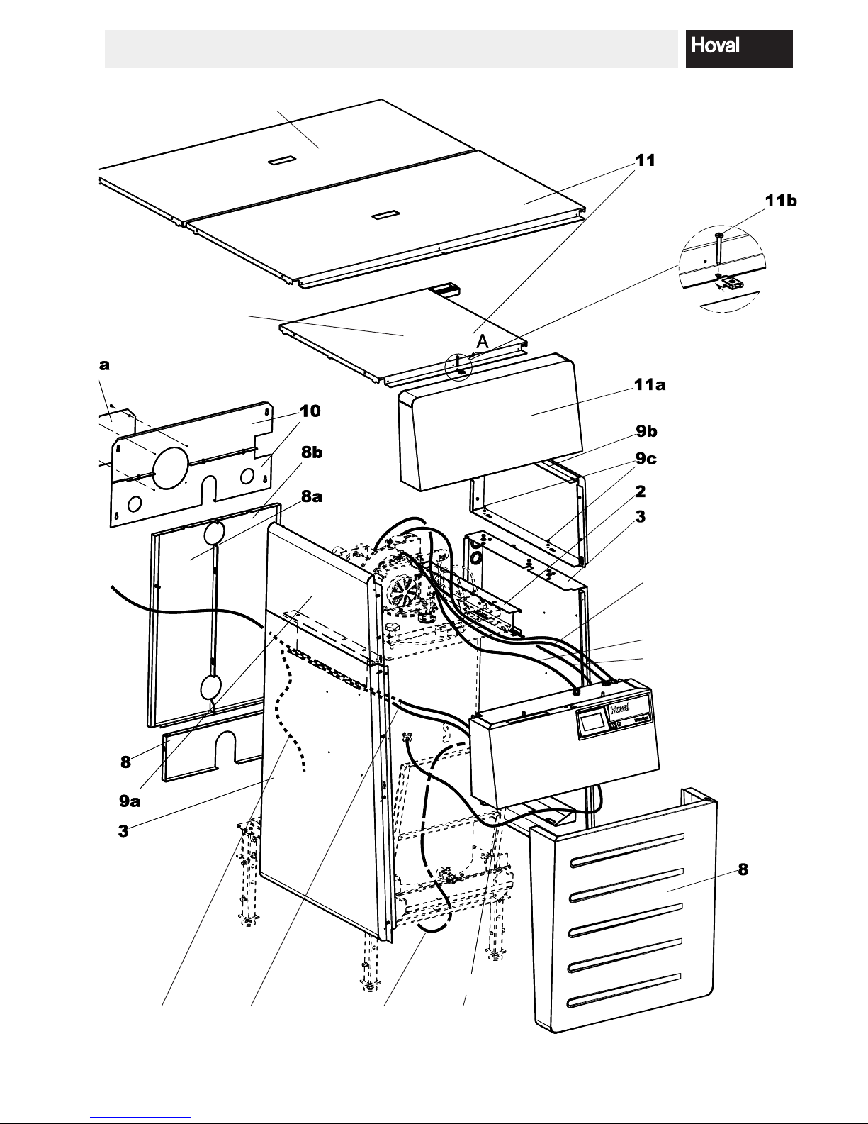
2.3 Fitting the casing
1. Hook the cable duct (2, Fig. 04) into the pins on the
left and right and attach with the middle hexagon nuts
and washers (3a, Fig. 04) already mounted on the
boiler. If there is a side wall support (2b, Fig. 07), turn
outwards to the side.
2. Hook in the side walls (4, Fig. 04) on the boiler and
secure with those outer hexagon nuts and washers
(4a, Fig. 04) already mounted on the boiler. Hook in
the side wall at the bottom on the screw head on the
condensate drip tray. Align the side walls centrally,
set the clearance for the electrical box and rear wall.
Then tighten hexagon nuts (4a, Fig. 04).
3. Attach rear wall (terminal plate 5, Fig. 05) of the terminal box using 4 screws (4a, Fig. 04).
4. Remove the stud (6 Fig. 05) on the left or right. Hook
in the electrical box at the bottom on the side of the
stud. Hold the electrical box horizontal and tighten
with the second stud on the opposite side. Fold the
electrical box closed upwards and hook in.
5. Fit trim strips (7, Fig. 08)
- Open terminal box to t the top screw (7a, Fig. 06)
- Close terminal box again to t the bottom screw
(7b, Fig. 08)
6. Route the cable for the water pressure sensor (7,
Fig. 08) down out of the control and connect to the
boiler at the bottom (cable routing acc. to Fig. 09).
Route all other cables on the left or right of the boiler
and make the plug connections.
CAUTION
The cables must not touch any hot parts.
7. Hook the lower rear wall (8, Fig. 09) onto the side
walls. Hook in the rear walls (8a, 8b, Fig. 09) on the
opposite side and engage together on the side walls.
8. Mount the upper side walls (9a, 9b, Fig. 09). Place
the underside of the upper side walls (long slot) onto
the special screws of the lower side walls and push
in. Secure the upper side walls using 4 self-trapping
screws (9c, Fig. 09) ø 3.5 x 10.
9. Hook in the upper rear walls (10, Fig. 09) and t the
dummy cover (10a).
10. Put on cover plates (11, Fig. 09). Install the upper
front (11a, Fig. 09) and place the pins in slits, then
push back. Following that, secure with carriage bolt
(11b, Fig. 09). (When taking down, lift one side followed by the other.)
11. Hook the front cover (8, Fig. 09) in at the bottom (from
type 575 onwards with rail) and push closed upwards
(secure with carriage bolt on the side). In a cascade
> 3, no carriage bolts are tted on the middle boilers!
12. The remaining 3 casing walls (15, 15a, 16, Fig. 11)
are tted after mounting the condensate box.
12
4 213 783 / 00
INSTALLATION
Fig. 04
Fig. 05
3a 244a
21-UltraGas (850)
2b
4a
Fig. 07
7
7b
Fig. 08
7c
Illustration shown without burner
5a
6 6a
5
7a
Fig. 06
Secure the service pedestal (7c, Fig. 08) in
the folded-up status with pin (1b, Fig. 02)!
13
4 213 783 / 00
INSTALLATION
Burner wiring
Model (125-850);
2 plug connections
Model (1000);
3 plug connections
Mains cable
Ignition cable
Water pressure
sensor
Condensate box
(if tted)
Boiler temperature sensor
Models (850,1000) in two-piece design
Type (125,720)
in one-piece design
Fig. 09
Flue gas sensor
7
14
4 213 783 / 00
INSTALLATION
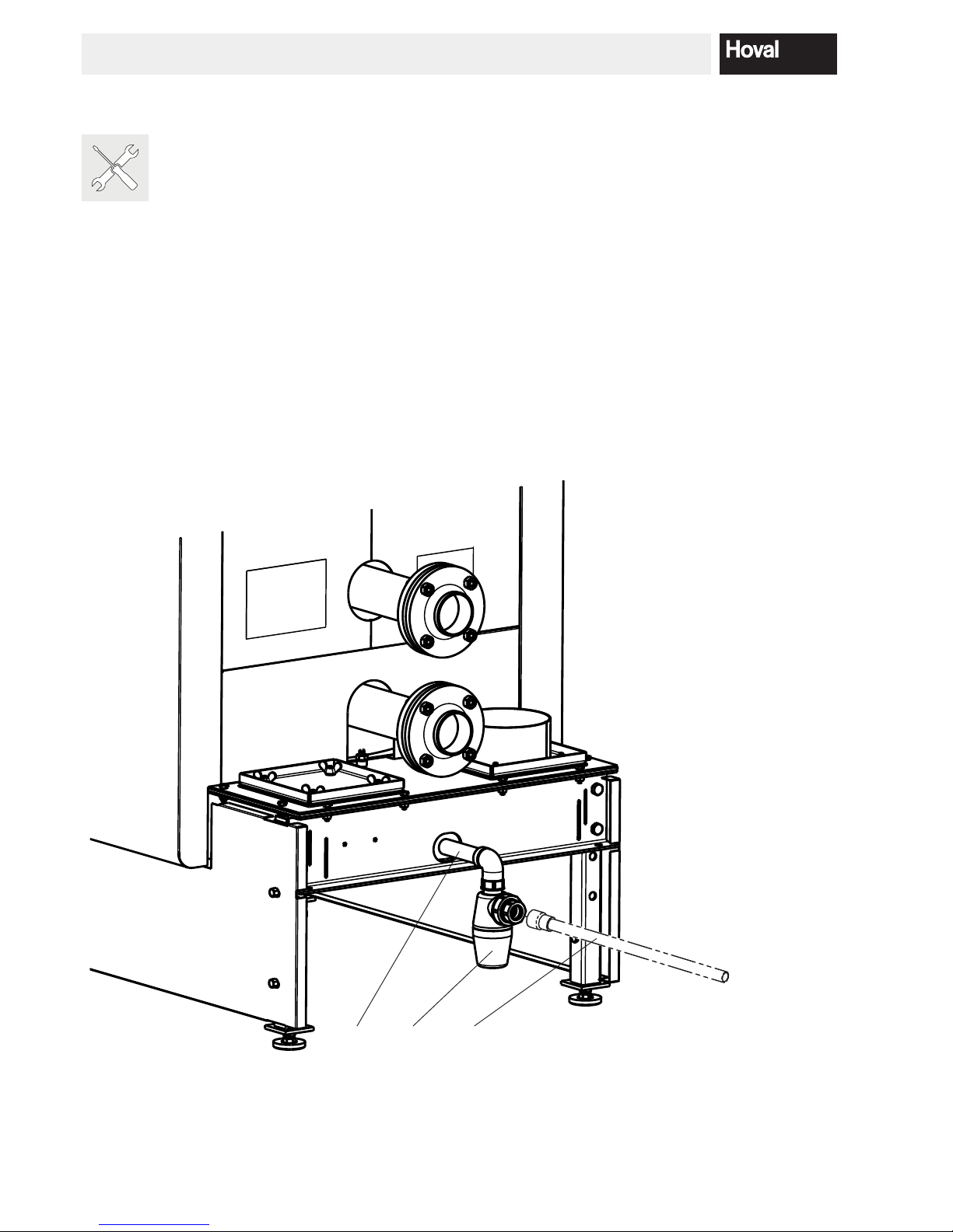
2.4 Fitting the pedestal casing
Attach the condensate trap (13, Fig. 10),
which is supplied loose, incl. double nipple
(13a, Fig. 10).
1. Place the condensate box (option) under the boiler
and establish the electrical connection. Make the
condensate drain or connection line according to separate instructions.
For UltraGas
®
(575,650,720,850,1000):
Fit condensate drain pipe (14, Fig. 10) (supplied with
the boiler)
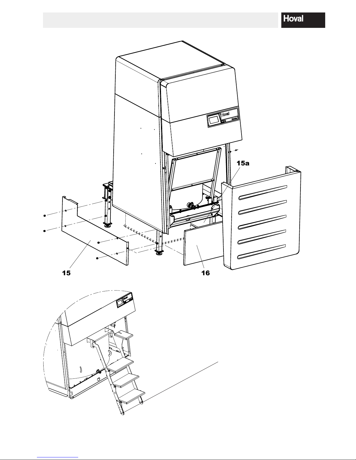
2. Screw the right and left side walls (15, 15a, Fig. 11)
using the cap nuts already mounted on the boiler foot.
3. Hook in the front (16, Fig. 11) on the side walls
(15, 15a, Fig. 11).
13a 13
14
Fig. 10
15
4 213 783 / 00
INSTALLATION
Fig. 11
Fig. 12
Only types UG (850,1000)
If you are using the variant with shortened boiler feet or you place the boiler
on a concrete pedestal, you will have to shorten the supplied conductors
(saw off at the watch) or extend them.
 Loading...