

Hoval UltraGas 15, UltraGas 27, UltraGas 20, UltraGas 35, UltraGas 50 Installation Instructions Manual
The oor standing gas condensing boiler UltraGas® are
designed and approved for use as heat generators for
hot water heating systems with a permissible ow temperature of up to 85ºC1), in accordance with EN 483 and
EN 677. They are designed for continuously adjustable
reduced output operation in heating systems.
1)
See technical data
Rated output levels at 40/30ºC
and for natural gas
30-UltraGas
®
(15) 3,1 - 15,5 kW
30-UltraGas® (20) 4,0 - 20,2 kW
30-UltraGas® (27) 5,0 - 27,2 kW
30-UltraGas® (35) 5,8 - 35,7 kW
30-UltraGas® (50) 8,3 - 50,1 kW
UltraGas® (15-50)
Condensing gas heating boilers
for natural gas and liquid gas
for modulating operation
Hoval products must be installed and commissioned
only by appropriately qualied experts. These instructions are intended exclusively for the specialist. Electrical installations may only be carried out by a qualied
electrician.
Subject to modi cations |
EN
Technical information
Installation instructions
4 210 264 / 04 - 08/13

4 210 264 / 04
2
Table of contents
1. Safety instructions
1.1 Key to symbols used .............................................................................................................................. 4
2. Important notes
2.1 Acceptance of delivery ........................................................................................................................... 4
2.2 Scope of guarantee ................................................................................................................................. 4
2.3 Instruction manuals ................................................................................................................................ 4
2.4 Regulations, official permits .................................................................................................................. 4
2.4.1 Germany § ................................................................................................................................................ 5
2.4.2 Austria § .................................................................................................................................................... 5
2.4.3 Switzerland § ............................................................................................................................................. 5
3. Assembly
3.1 Set-up, levelling ....................................................................................................................................... 6
4. Technical data
4.1 Description of the boiler ......................................................................................................................... 7
4.2 Technical data .........................................................................................................................................8
4.3 Dimensions .............................................................................................................................................. 9
4.4 Space requirements .............................................................................................................................. 10
4.5 Boiler-Flow resistance .......................................................................................................................... 11
4.6 Brief description of the automatic firing device ................................................................................ 11
5. Installation
5.1 Safety information ................................................................................................................................. 12
5.2 Boiler room requirements .................................................................................................................... 12
5.2.1 Room air dependent installation .............................................................................................................. 12
5.2.2 Room sealed installation ......................................................................................................................... 12
5.3 Flue gas connection and flue ............................................................................................................... 13
5.4 Condensate drainage ............................................................................................................................ 14
5.5 Design variants ..................................................................................................................................... 14
5.6 Fitting the condensate drain (standard design with siphon) ............................................................ 15
5.7 Fitting the neutralisation box (if fitted) ............................................................................................... 16
5.8 Fitting the condensate delivery pump ................................................................................................ 17
5.9 Fitting the neutralisation box and the condensate delivery pump ................................................... 18
5.10 Hydraulic connection ............................................................................................................................ 20
5.10.1 Customer-side requirements ................................................................................................................... 20
5.10.2 Hydraulic interconnection ........................................................................................................................ 20
5.11 Electrical connection ............................................................................................................................ 21
6. Commissioning
6.1 Safety information ................................................................................................................................ 22
6.2 Filling with water ................................................................................................................................... 22
6.3 Water quality .......................................................................................................................................... 23
6.4 Bleeding the air from the gas line ....................................................................................................... 24
6.5 Switching on the system ...................................................................................................................... 24
6.6 Gas inlet pressure ................................................................................................................................. 24
6.7 Setting the gas flow rate CO2(O2) and measurement of NOx/CO content in the flue gas
(flue gas measurement) ........................................................................................................................ 25
6.8 Changing over to a different gas type ................................................................................................. 26
6.9 Handover to the user ............................................................................................................................ 26
6.10 Record - Activation of screed function ............................................................................................... 27

4 210 264 / 04
3
Table of contents
7. Maintenance
7.1 Safety information ................................................................................................................................ 29
7.2 Bleeding ................................................................................................................................................ 29
7.3 Water refilling ....................................................................................................................................... 29
7.4 Information for combustion controller/chimney sweep regarding emission monitor key ............. 30
7.5 Cleaning ................................................................................................................................................. 31
7.5.1 Cleaning the burner cylinder ................................................................................................................... 31
7.5.2 Cleaning the exterior of the combustion chamber and burner cylinder ................................................... 32
7.5.3 Cleaning/adjusting the ignition and ionisation device ..............................................................................33
7.6 Setting the gas flow rate CO2(O2) and measurement of NOx/CO content in the flue gas (flue gas
measuring according to point 6.7) ..................................................................................................... 33
7.7 Clean siphon or neutralisation box .................................................................................................... 34
7.8 Maintenance of the Neutralisation equipment (if available) .............................................................. 35
7.8.1 Procedure for servicing the neutralisation installation ............................................................................. 35
8. Overview of settings
8.1 Table of parameters .............................................................................................................................. 36
8.2 FIRING DEVICE UltraGas® (15-50) ....................................................................................................... 43
8.3 Fault Reporting overview TopTronic®T ................................................................................................ 48
8.4 Automatic firing device (Warning, Blocking, Lock-out) ..................................................................... 50
4 210 264 / 04
4
Safety instructions
1. Safety instructions
i
The system shall not be put into operation until all relevant standards and safety regulations are met.
For a test run, the following minimum conditions
must be satisfied:
- Safety valve installed (closed system)
- Controls operative (connected to power supply)
- Sensor for safety temperature limiter is connected
(= boiler temperature sensor)
- System filled with water
- Siphon filled with water
- Expansion tank connected
- Flue gas adapter pipe with flue gas pipe connected to flue.
- Burner is preset (see point 6.7).
1.1 Key to symbols used
Tools:
Shows the tools required for the following
work.
Result:
Shows the expected reaction to your action.
i
Note:
Provides important information.
Safety information:
Indicates an immediate hazard to persons.
Safety information:
Warning of dangerous electrical voltage.
Warning information:
Indicates danger to machines and Installations.
§
Provides important information.
Reference to standards and regulations.
2. Important notes
2.1 Acceptance of delivery
i
A visual control of the heating boiler
should be conducted upon delivery.
In the event of damage, the necessary
steps should be followed as specified in
the delivery contract. The costs for cor-
recting the damage shall be taken over
by the individual risk bearer.
2.2 Scope of guarantee
i
The guarantee does not cover defects
caused by:
- non-observance of these instructions
- non-observance of the operating instructions
- incorrect Installation
- unauthorised alterations
- improper use
-
contaminated operating media (gas,
water, combustion air)
-
unsuitable chemical additives to the
heating water
- damage due to the exercise of force
- corrosion through halogen compounds
- corrosion through nonconforming water quality
2.3 Instruction manuals
i
A summary of all the instruction manuals
relevant to this system can be found in
the Hoval System User Guide! In exceptional cases the instructions are kept with
the respective components!
Additional sources of information:
- Hoval catalogue
- Standards and regulations
2.4 Regulations, official permits
i
When installing and operating the system, the standards and regulations speci fied in point 2.4.1 to 2.4.3 must be complied with at all times.

4 210 264 / 04
5
Important notes
2.4.1 Germany §
• DIN EN 12831 Heating systems in buildings Methods for calculating the design heat load
• DIN EN 13384 Flue gas systems - Heat and flow
calculation methods
• DIN EN 12828 Heating systems in buildings Planning of hot water heating systems.
• DIN 4755 Oil fired combustion systems.
• Construction, design, safety requirements.
• DIN 4756 Gas fired combustion systems. Construction, design, safety requirements, design and
execution (for gas burner operation).
• DIN 18160 Domestic chimneys, requirements, design and construction.
• TRD 702 Steam boilers with group II hot water
generators.
• TRD 721 Safety equipment against excessive
pressure / safety valves for group II steam boilers.
• VDI 2035 Prevention of damage through corrosion
and scale formation in hot water heating systems.
• DIN 57 116 / VDI 0116 Electrical equipment in
combustion systems (VDE regulation).
• See enclosure N-430 020 for further standards applicable in Germany.
2.4.2 Austria §
• OENORM 12831 Heating systems in buildings Methods for calculating the design heat load
• OENORM 13384 Flue gas systems Heat and flow calculation methods
• OENORM 12828 Heating systems in buildings Planning of hot water heating systems.
• ÖNorm B 8130 Open water heating systems;
safety equipment.
• ÖNorm B 8131 Closed water heating systems;
requirements to safety, construction and testing.
• ÖNorm B 8133 Hot water supply systems;
safety requirements.
• ÖNorm B 8136 Heating systems,
space and other building requirements.
• ÖNorm M 7515 Dimensioning of chimneys;
definitions and calculation procedure.
• ÖNorm H 5171 Heating systems -
construction requirements for buildings.
• ÖVGW TR-Gas
2.4.3 Switzerland §
• SN EN 12831 Heating systems in buildings -
Methods for calculating the design heat load
• SN EN 13384 Flue gas systems -
Heat and flow calculation methods
• SN EN 12828 Heating systems in buildings -
Planning of hot water heating systems.
• VKF - Association of Cantonal Fire Insurances.
• Fire service regulations.
• SVGW Switzerland.
Association of the gas and water trade.
• SNV 27 10 20 Ventilation requirements for the boiler Installation room.
• SWKI BT102-01 Quality of water in installations
of building technology.
• Technical tank regulations TTV 1990.
and further standards and regulations issued by
CEN, CEN ELEC, DIN, VDE, DVGW, TRD and by
the legislator. Regulations from the local building authority, insurance companies and chimney sweeps
must also be complied with. When using gas as fuel,
the regulations of the responsible gas board must
also be observed. An official permit may be required.
4 210 264 / 04
6
Assembly
3. Assembly
3.1 Set-up, levelling
The boiler is fixed to wooden transport chocks. For
transport up and down stairs, it is wise to leave these
timbers in place under the boiler.
A special foundation plate for the boiler is not an essential, but it is recommended.
Space requirement
For further information on space requirements, see
chapter 4.4.
The cleaning apertures must be easily
accessible.
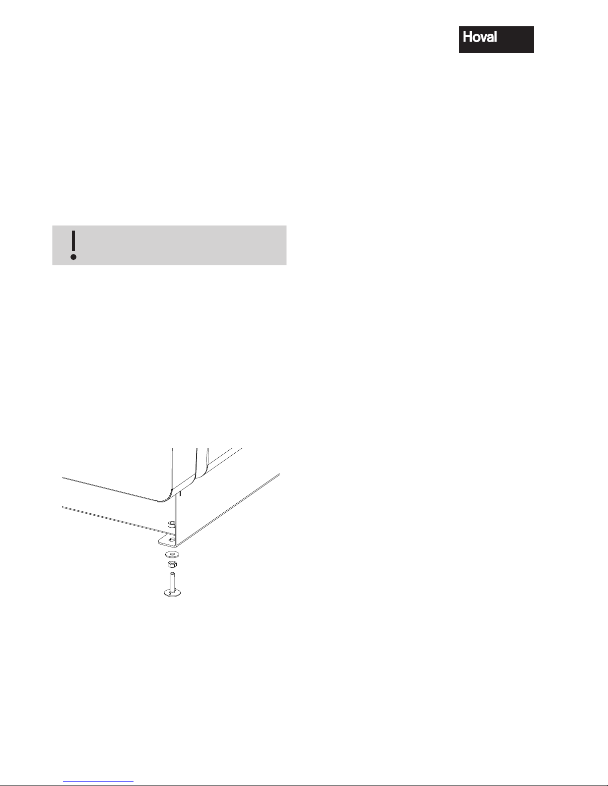
Installing and levelling the boiler
Remove transport chocks. Store nuts and washers.
Lift the boiler on one side and put grub screws of
boiler base from the bottom through the slot of the
boiler sockets. Fix boiler feet using hexagonal nuts
(figure 01).
Using a spirit level, set the boiler in longitudinal and
transverse direction and position it with a slight forward
tilt. This is done by adjusting the nuts on the boiler
feet. After this adjustment, the upper (locking) nuts
on the boiler feet must be tightened.
Fig. 01
4 210 264 / 04
7
Technical data
4. Technical data
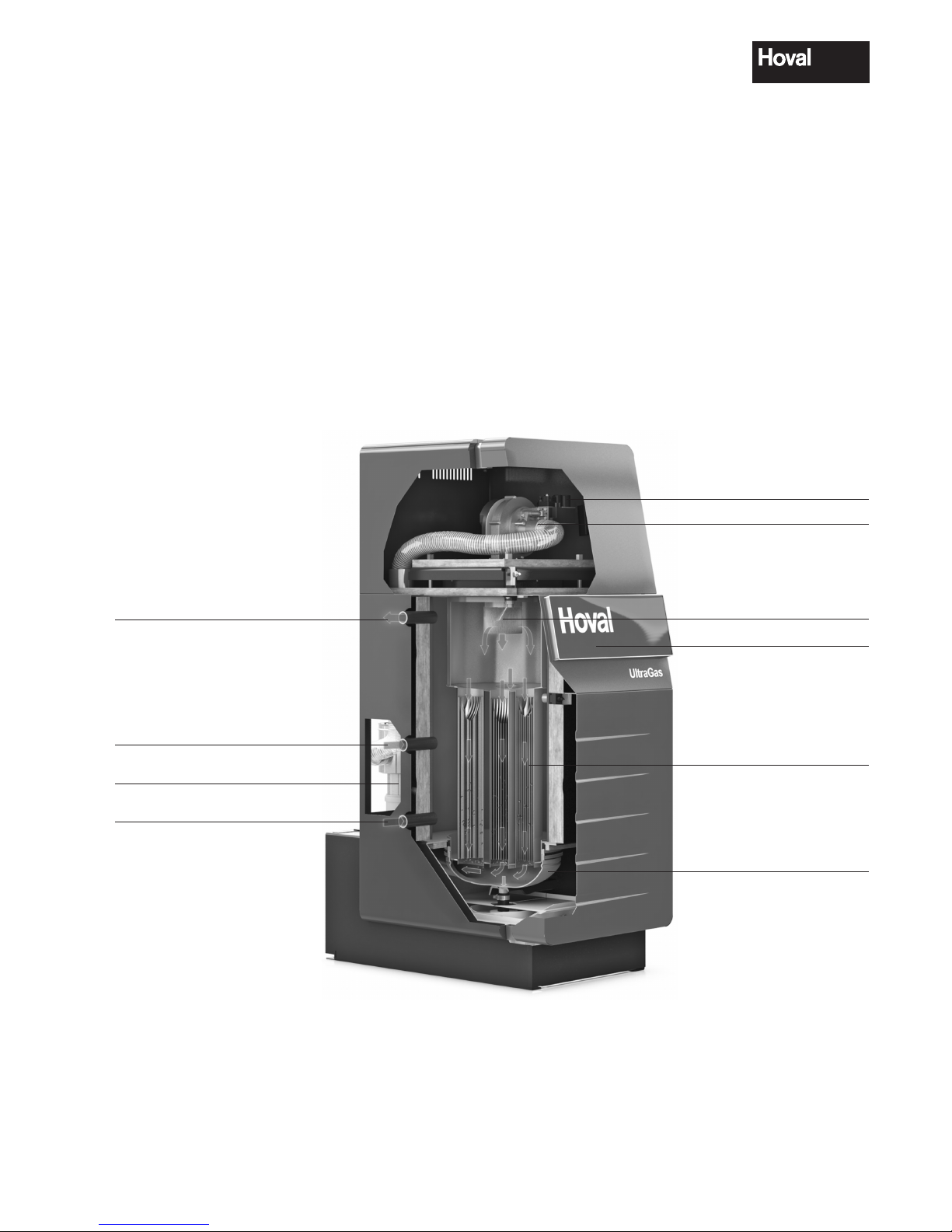
4.1 Description of the boiler
The Hoval UltraGas® is a low emission, energy-saving
condensing gas boiler comprising the Ultraclean
burner system, a gas fired premix burner with combustion air fan. The Hoval UltraGas® has a vertically
disposed combustion chamber of stainless steel as
a primary heating surface and a secondary heating surface of a corrosion resistant aluminium alloy.
The secondary heating surface is designed so that
part of the water vapour contained in the flue gas is
condensed and the vaporisation heat it contains is
utilised for the heating circuit. The gas burner is in the
form of a break draught burner, which can easily be
swung up for maintenance purposes. The UltraGas
®
is designed to operate with natural and liquid gas. The
figure below shows the design principle.
Feed tube on left and/or right side
High temperature return
on left and/or right side
Low temperature return
on left and/or right side
Gas safety and control devices
Combustion air fan
Electrode for ignition
and flame monitoring
TopTronic
®
T controller
aluFer
®
heat exchanger
Condensate collection tray
Flue gas connection

4 210 264 / 04
8
Technical data
4.2 Technical data
UltraGas® (15-50)
Type (15) (20) (27) (35) (50)
• Nominal output 80/60°C with natural gas
1
kW 3,0-14,0 3,8-18,2 4,5-24,5 5,2-32,2 7,5-45,2
• Nominal output 40/30°C with natural gas
1
kW 3,3-15,5 4,3-20,3 5,0-27,2 5,8-35,7 8,3-50,1
• Nominal output 80/60°C with liquid gas
2
kW 4,5-13,8 4,9-18,6 6,6-24,3 6,9-32,2 9,9-45,5
• Nominal output 40/30°C with liquid gas
2
kW 5,0-15,3 5,5-20,7 7,3-27,0 7,7-35,7 10,9-50,5
• Nominal load with natural gas
1
kW 3,1-14,5 4,0-19,0 4,7-25,4 5,4-33,3 7,7-46,9
• Nominal load with liquid gas
2
kW 4,7-14,3 5,1-19,3 6,8-25,2 7,2-33,4 10,2-47,2
• Working pressure heating max./min. bar 3,0 / 1,0 3,0 / 1,0 3,0 / 1,0 3,0 / 1,0 3,0 / 1,0
• Working temperature max.. °C 85 85 85 85 85
• Boiler water capacity l 57 55 51 81 75
• Flow resistance boiler
3
z-value 3,5 3,5 3,5 1,1 1,1
• Min. water circulation l/h 0 0 0 0 0
• Boiler Weight (without water content, incl. casing) kg 131 135 143 161 174
• Boiler efficiency at partial load 30% (according to EN 303)
(related to net / gross calorific value)
107,1/96,5 106,9/96,3 106,7/96,1 106,7/96,1 106,9/96,3
• Standard efficiency 40/30°C % 109,5/98,6 109,5/98,6 109,5/98,6 109,5/98,6 109,5/98,6
(net calorific value / gross calorific value) 75/60°C % 107/96,4 107/96,4 107/96,4 107,0/96,4 107,0/96,4
• Heat loss rate at 70°C Watt 160 160 160 220 220
• Standard emission rate NOx. mg/kWh 25 26 28 31 29
CO. mg/kWh 11 11 10 11 4
• Content of CO
2
in the exhaust gas max./min. power % 9,0 / 8,8 9,0 / 8,8 9,0 / 8,8 9,0 / 8,8 9,0 / 8,8
• Dimensions See table of dimensions
• Connections Flow /ReturnInches R 1" R 1" R 1" R 1¼" R 1¼"
Gas Inches Rp ¾" Rp ¾" Rp ¾" Rp ¾" Rp ¾"
Flue gas Ø mm E80 E80 E80 E80 E80
• Gas flow pressure min./ max.
Natural gas E/LL mbar 18-50 18-50 18-50 18-50 18-50
Liquid gas mbar 37-50 37-50 37-50 37-50 37-50
• Gas connection value at 0°C / 1013 mbar:
Natural gas E - (Wo = 15,0 kWh/m
3
) Hu = 9,97 kWh/m
3
m3/h 1,5 1,9 2,6 3,3 4,7
Natural gas LL- (Wo = 12,4 kWh/m
3
) Hu = 8,57 kWh/m
3
m3/h 1,7 2,2 3,0 3,9 5,5
Propane gas (Hu = 25,9 kWh/m
3
) m3/h 0,6 0,8 1,0 1,3 1,8
• Operation voltage V/Hz 230/50 230/50 230/50 230/50 230/50
• Control voltage V/Hz 24/50 24/50 24/50 24/50 24/50
• Min./Max. electrical power consumption Watt 24/46 24/64 24/58 29/98 30/122
• Standby Watt 12 12 12 12 12
• IP rating (integral protection) IP 20 20 20 20 20
• Acoustic capacity
- Heating noise (EN 15036 part 1) (room air-dependent) dB(A) 57 61 66 62 60
- Exhaust noise is radiated from the mouth
(DIN 45635 part 47) (room air-dependent/room air-independent)
dB(A) 43 49 55 55 58
• Acoustic pressure level (depending on installation)
4
dB(A) 50 56 59 55 53
• Condensate quantity (Natural gas ) at 40/30°C l/h 1,3 1,8 2,4 3,1 4,4
• pH value of the condensate pH ca. 4,2 ca. 4,2 ca. 4,2 ca. 4,2 ca. 4,2
• Value for flue calculation
Temperature class T120 T120 T120 T120 T120
Flue gas mass flow kg/h 23 31 42 55,0 78,0
Flue gas temperature at nominal output and operation 80/60°C °C 62 63 64 65 68
Flue gas temperature at nominal output and operation 40/30°C °C 45 45 45 46 46
Mass flow combustion air Nm
3
/h 17 23 31 41 58
Feed pressure for combustion air/ flue gas system Pa 100 100 100 120 120
Maximal Draft / negative pressure flue gas outlet Pa - 50 - 50 - 50 - 50 - 50
1
Data related to Hu. The boiler series is tested for EE/H-settings. With a factory setting of the Wobbe coefficient of 15,0 kWH/m3
operation at a Wobbe coefficient of 12,0 up to 15,7 kWh/m3 is possible (a readjustment may be necessary).
2
Data related to Hu.
3
Flow resistance boiler in mbar = volume flow (m3/h)2 x z
4
See also notes at „Engineering“.
• Boiler flow resistence see diagram.
4 210 264 / 04
9
Technical data
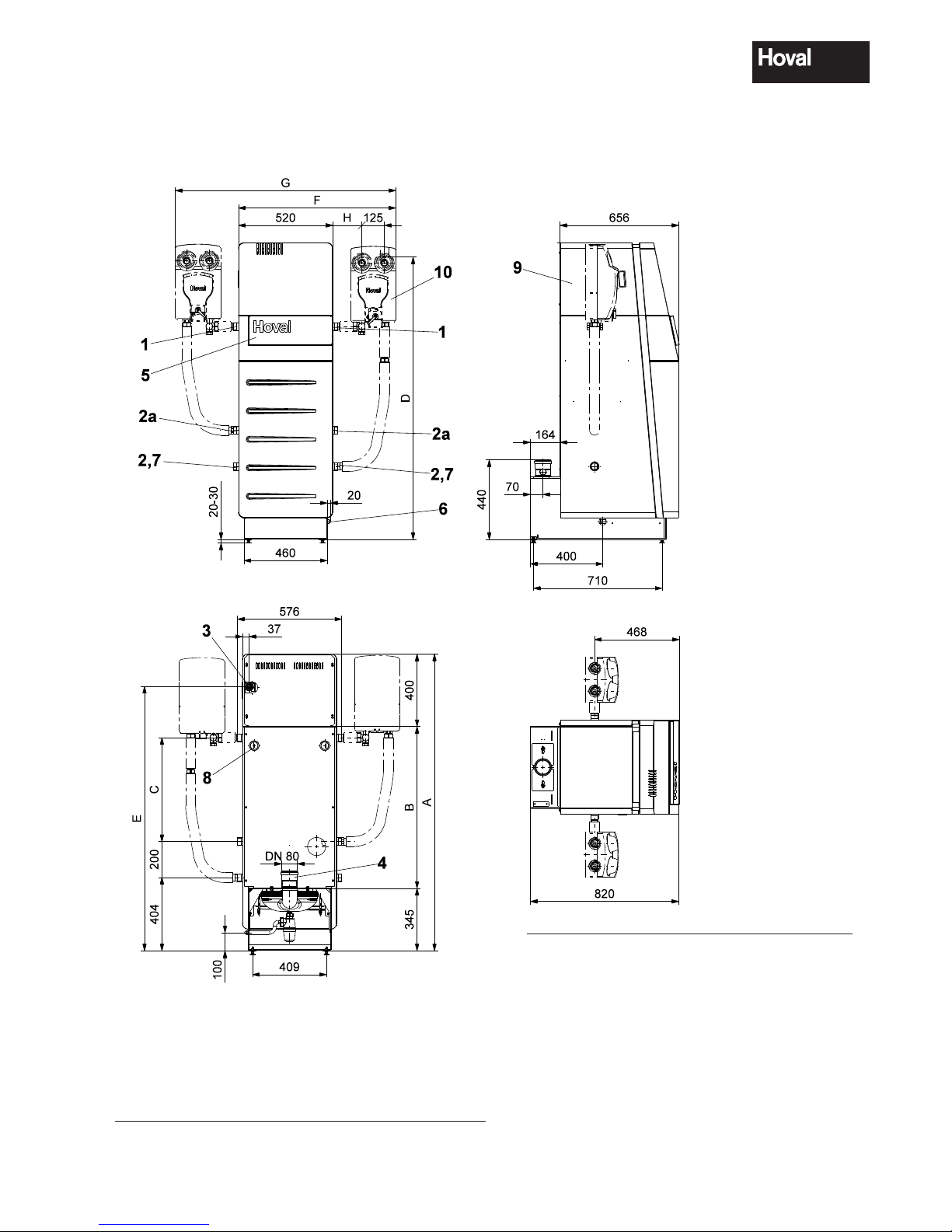
4.3 Dimensions
(Dimensions in mm)
Type A B C D E F G H
UltraGas
®
(15-27) 1400 655 333 1320 1220 852 1184 144
UltraGas
®
(35,50) 1640 895 573 1560 1460 930 1340 222
Type UltraGas
®
(15-27) (35,50)
1 Heating flow / safety flow R 1" R 1¼"
2 Low temperature-return R 1" R 1¼"
2a High temperature-return R 1" R 1¼"
3 Gas connection Rp ¾" Rp ¾"
4 Flue gas outlet DN80 DN80
5 Boiler control
6 Condensate drain (left or right) incl.
siphon DN25 and 2 m PVC continuous-
flow tube inner Ø 19 x 4 mm
7 Draining
8 Electric cable entry point
9 Sound absorber hood
10 Heating armature group
or loading group (Option)
4 210 264 / 04
10
Technical data
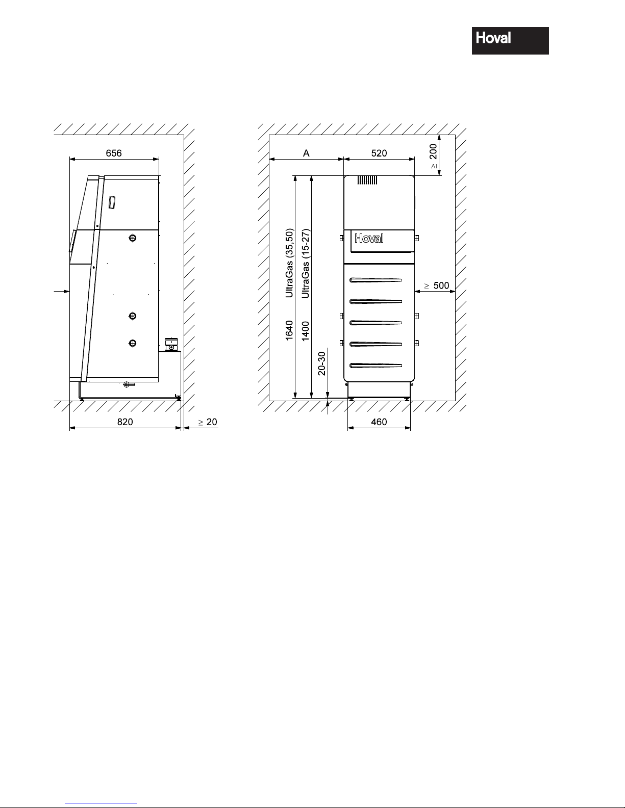
4.4 Space requirements
(Dimensions in mm)
Boiler door incl. burner swings upward and to the left
or outward.
A = minimum 150 mm *
Burner service position front - boiler cleaning
from the right
A = optimum 300 mm *
- Burner service position left - boiler cleaning
from the front
- Boiler can be placed with the right side directly against the wall
- however, a minimum gap of 160 mm is required.
* without armature group,
500 mm with armature group
- The cleaning aperture must be easily accessible.
- Ensure access to the area behind the boiler.

4 210 264 / 04
11
Technical data
4.5 Boiler-Flow resistance
UltraGas® (15-27)
UltraGas
®
(35,50)
0
5
10
15
20
25
30
0 0,5 1 1,5 2 2,5 3 3,5 4 4,5 5
[m
3
/h]
[mbar]
m3/h = Volume flow
mbar = Flow resistance
0
5
10
15
20
25
30
35
0123
[m3/h]
[mbar]
4.6 Brief description of the automatic firing device
The automatic firing device BIC960 of the
UltraGas® only operates in conjunction with the
heating controller
TopTronic®T/UG. For this rea-
son, the automatic firing device only needs to take
care of the last remaining functions to ensure the
correct operation of a modulating gas boiler.
The automatic firing device comprises the following
functions:
- PWM fan control (230V AC)
- Modulating operation
- Common electrode for ignition and flame monitoring (ionisation)
- LPG valve and boiler room fan controllable
- Inputs for
flow sensor 1
flow sensor 2
flue gas sensor
water pressure sensor
safety temperature limiter (not used)
air pressure switch (not used)
gas pressure switch
- Status outputs “fault” and “flame signal”
- Allows connection of additional (external) ignition
device
- RS 485 connection to TopTronic®T/UG
- RS 232 connection to PC
- Start attempts: maximum 4
- Safety period: 5 sec
- Pre-ignition period: 5 sec
- Pre-purging period: 50 sec
- Follow-on time pump (230V AC): 5 min after heat
demand
Fuses:
The BIC 960 is fitted with 3 fuses:
2AT Mains
4AT Pump
4AT Burner fan
Blowing of one of the two 4AT fuses securing the
pump or the burner fan, respectively, will prevent
the affected device from starting.
A failure of the mains fuse of the automatic firing
device is displayed on the TopTronic
®
T/UG by the
failure message „DATABUS ERROR 70-6“. The
failure appears when there is no communication
between automatic firing device and TopTronic
®
T/
UG.

4 210 264 / 04
12
Installation
5. Installation
5.1 Safety information
Caution!
Sharp edges pose a cutting hazard.
Handle the cladding parts with care
and avoid contact with sharp edges.
5.2 Boiler room requirements
§
- The boiler room must satisfy the applicable local building regulations.
- The boiler room ventilation must satisfy
the applicable local regulations in this
regard.
-
Boilers may not be installed in rooms
containing halogen compounds which
can be carried into the combustion air
(e.g. wash rooms, drying rooms, DIY
rooms, hair dresser rooms).
-
Halogen compounds can originate, for
example, from cleaning and degreasing agents, solvents, glue, and bleaching lyes.
Ensure that the required combustion air can flow unhindered at all times. This is important for the correct
operation of all the boilers installed therein and to
protect the users from an oxygen depleted atmosphere. An adequate fresh air supply meeting the local regulations must be provided.
5.2.1 Room air dependent installation
• The applicable regulations do not normally provide
any specific data on the size of air intakes. They
only require the pressure in the boiler room not to
be below 3 N/m2.
• This means that for a rated thermal output of up to
50 kW an air intake with a cross section of at least
300 cm2 must be available.
• For rectangular apertures the aspect ratio should
not exceed 1.5:1. If a grid is fitted on the air intake,
a suitable allowance must be made to obtain an air
intake cross section of 300 cm
2
.
5.2.2 Room sealed installation
Configuration based on a concentric flue system:
• The suction air is supplied through a double-wall
flue system.
• Ensure the boiler room is sufficiently ventilated.
Configuration using a separating piece (optional):
i
The following must be observed when
laying out the intake pipe:
- If the intake opening is installed on the
house facade near to a noise-sensitive
area (e.g. bedroom windows, garden
seating area, etc.) we recommend in-
stalling a noise damper in the direct
fresh air suction line.
- The intake opening must be easily accessible.
- No chemicals or poisonous substances
may be stored close to the intake opening
- The intake opening may not be installed
beside fume extraction outlets or other
venting outlets.
-
Ensure that the intake aperture is
free from any obstructions at all times
(leaves, snow, ...)
-
A safety grid must be installed on the
suction opening on the outside wall.

4 210 264 / 04
13
Installation
5.3 Flue gas connection and flue
Due to the low flue gas temperatures, condensate
forms within the flue. For this reason, Hoval gas
heating boilers can not be connected to conventional house chimneys.
i
§
The flue gas extraction system must
comply with the following directives:
- DVGW (TRGI)
- ÖVGW
- SVGW/VKF
Pursuant to the abovementioned regulations, a flue gas temperature limiter must
be installed in the boiler.
i
The flue gas system must meet the
following requirements:
- Gastight
- Watertight
- Acid-proof
-
Approved for flue gas temperatures of
up to 120ºC (T 120)
- Approved for overpressure
i
Unhindered back flow of condensate into
the boiler can only be ensured if:
The gradient of the horizontal connection
elements is at least 50 mm/m..
i
§
Only one heat generator may be connected to the same chimney.
If two heat generators are to be con-
nected to the same chimney, the relevant
regulations must be complied with.
i
Cross sections and maximum lengths
are calculated on the basis of graphs or
tables. The tables can be obtained from
the chimney or flue system manufacturer.
The calculation values can be obtained
from the table under point 4.2.
The flue gas conduit cross sections and
lengths are calculated following the technical data for the boiler.
The concentric supply air/exhaust sys-
tem of the boiler can also be conducted
horizontally backwards. The Hoval remodelling set allows a remodelling on site.
4 210 264 / 04
14
Installation
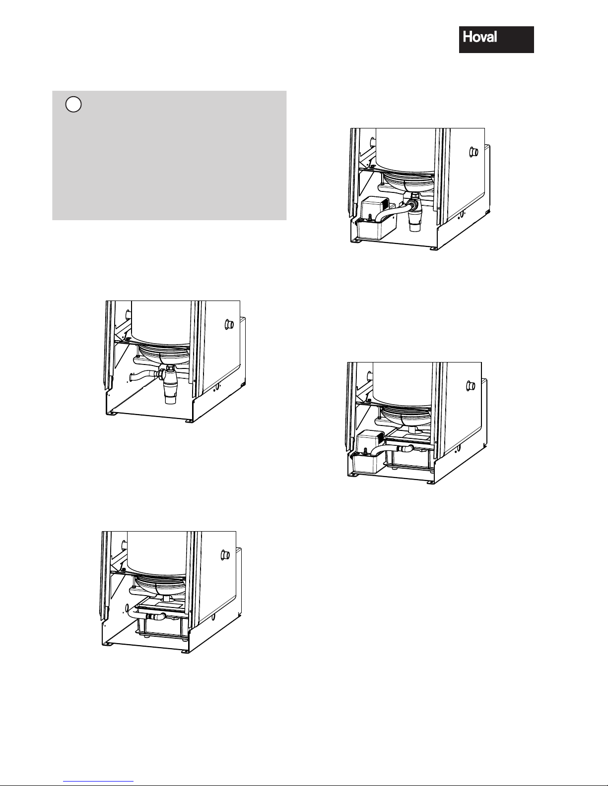
Possibility 3 - see chapter 5.8
• Siphon and condensate delivery pump
• Without neutralisation, condensate discharge into
higher drain line.
Fig. 04
Possibility 4 - see chapter 5.9
• Neutralisation box and condensate delivery pump
• With condensate neutralisation - condensate discharge into higher drain line.
Fig. 05
5.4 Condensate drainage
i
The condensate drainage pipes on
the boiler must be made of corro-
sion resistant material. The following
materials are suitable for condensate
drainage:
PVC, PE, PP, ABS
The local regulations regarding condensate drainage must be observed.
5.5 Design variants
Possibility 1 - see chapter 5.6
• Execution with siphon
• Condensate discharge into lower drain line.
Fig. 02
Possibility 2 - see chapter 5.7
• Execution with neutralisation box
• For condensate discharge in lower drain line, incl.
condensate neutralisation.
Fig. 03
4 210 264 / 04
15
Installation
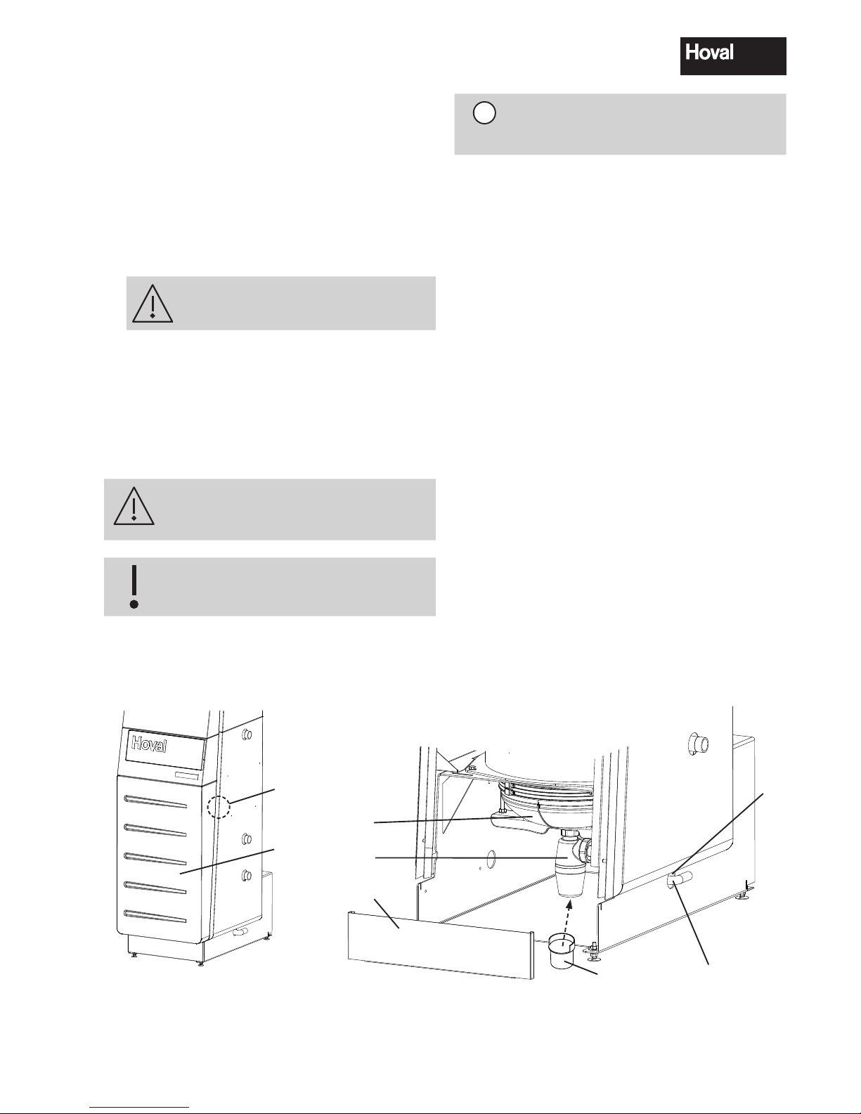
5.6 Fitting the condensate drain (standard design with siphon)
1. Remove front cover (1a, fig. 06). Release lateral
locking bolt (1, fig. 06) (approx. ¼ turn to the left).
Lift the front cover straight upwards and remove
towards the front.
2. Remove base plate (2, fig. 06). Lift base plate
straight upwards and remove.
3. Screw siphon (3) on the condensate tray (4) and
tighten securely (connection must be sealed)!
4.
Slide the siphon support (3a) under the siphon.
6. Fit drain (5) on siphon (3) and lead it outwards
(optionally left or right side) through the aperture
(5a).
7. Fit connecting line (5) to the drain line (2m hose
enclosed with the boiler).
8. Reattach front cover (1a, fig. 06) and base plate
(2, fig. 06).
Before commissioning, the siphon must
be filled with water in order to prevent
flue gas leakage..
The condensate drain must be made
of corrosion-resistant material.
1
1a
Fig. 06
2
3
5
5a
4
3a
i
If a neutralisation box is to be fitted, you
will find the further installation steps on
the next page.
4 210 264 / 04
16
Installation
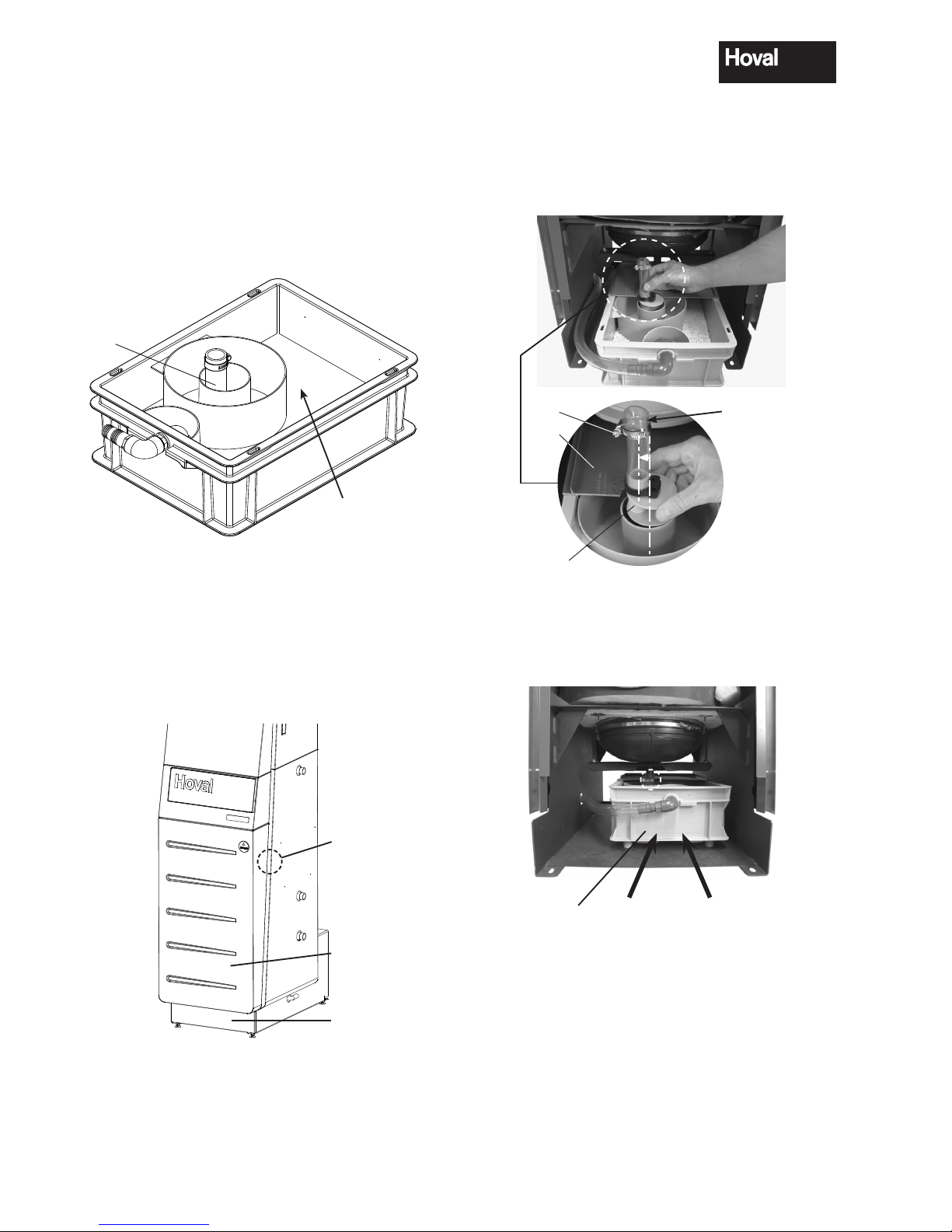
5.7 Fitting the neutralisation box (if fitted)
1. Remove the neutralisation box from its packaging. Remove the front and rear cover of the
neutralisation box.
2. Empty the neutralisation granulate (Neutroxid)
into the neutralisation box and distribute evenly.
Neutralisation granulate
(Neutroxide)
front
6
Fig. 07
3. Remove front cover (1a, fig. 08). Release lateral
locking bolt (1, fig. 08) (approx. ¼ turn to the left).
Lift the front cover straight upwards and remove
it towards the front.
4. Remove base plate (2, fig. 08). Lift the base plate
straight upwards and remove it.
1
1a
2
Fig. 08
5. Fit rear cover (9, fig. 09) of the neutralisation box.
6. Fit jubilee clip (10, fig. 09) approx. 20mm from
the upper end of the hose and tighten slightly.
The hose (10a, fig. 09) of the connection eccentric (10b, fig. 09) must be aligned towards the left.
10
9
10a
10b
Fig. 09
7. Slide the neutralisation box (11, fig. 10) into the
boiler until the hose of the siphon (6, fig. 07) is
directly beneath the drain connection.
11
Fig. 10
 Loading...